EP2455818A2 - Image forming apparatus - Google Patents
Image forming apparatus Download PDFInfo
- Publication number
- EP2455818A2 EP2455818A2 EP11186154A EP11186154A EP2455818A2 EP 2455818 A2 EP2455818 A2 EP 2455818A2 EP 11186154 A EP11186154 A EP 11186154A EP 11186154 A EP11186154 A EP 11186154A EP 2455818 A2 EP2455818 A2 EP 2455818A2
- Authority
- EP
- European Patent Office
- Prior art keywords
- toner
- paddle
- feed opening
- developing unit
- image forming
- Prior art date
- Legal status (The legal status is an assumption and is not a legal conclusion. Google has not performed a legal analysis and makes no representation as to the accuracy of the status listed.)
- Withdrawn
Links
- 238000000465 moulding Methods 0.000 claims description 3
- 239000010408 film Substances 0.000 description 3
- 230000015572 biosynthetic process Effects 0.000 description 2
- 230000003247 decreasing effect Effects 0.000 description 2
- 239000011347 resin Substances 0.000 description 2
- 229920005989 resin Polymers 0.000 description 2
- 239000010409 thin film Substances 0.000 description 2
- 238000004140 cleaning Methods 0.000 description 1
- 238000000034 method Methods 0.000 description 1
- 230000002093 peripheral effect Effects 0.000 description 1
- 230000003245 working effect Effects 0.000 description 1
Images




Classifications
-
- G—PHYSICS
- G03—PHOTOGRAPHY; CINEMATOGRAPHY; ANALOGOUS TECHNIQUES USING WAVES OTHER THAN OPTICAL WAVES; ELECTROGRAPHY; HOLOGRAPHY
- G03G—ELECTROGRAPHY; ELECTROPHOTOGRAPHY; MAGNETOGRAPHY
- G03G15/00—Apparatus for electrographic processes using a charge pattern
- G03G15/06—Apparatus for electrographic processes using a charge pattern for developing
- G03G15/08—Apparatus for electrographic processes using a charge pattern for developing using a solid developer, e.g. powder developer
-
- G—PHYSICS
- G03—PHOTOGRAPHY; CINEMATOGRAPHY; ANALOGOUS TECHNIQUES USING WAVES OTHER THAN OPTICAL WAVES; ELECTROGRAPHY; HOLOGRAPHY
- G03G—ELECTROGRAPHY; ELECTROPHOTOGRAPHY; MAGNETOGRAPHY
- G03G15/00—Apparatus for electrographic processes using a charge pattern
- G03G15/06—Apparatus for electrographic processes using a charge pattern for developing
- G03G15/08—Apparatus for electrographic processes using a charge pattern for developing using a solid developer, e.g. powder developer
- G03G15/0822—Arrangements for preparing, mixing, supplying or dispensing developer
- G03G15/0887—Arrangements for conveying and conditioning developer in the developing unit, e.g. agitating, removing impurities or humidity
- G03G15/0889—Arrangements for conveying and conditioning developer in the developing unit, e.g. agitating, removing impurities or humidity for agitation or stirring
-
- G—PHYSICS
- G03—PHOTOGRAPHY; CINEMATOGRAPHY; ANALOGOUS TECHNIQUES USING WAVES OTHER THAN OPTICAL WAVES; ELECTROGRAPHY; HOLOGRAPHY
- G03G—ELECTROGRAPHY; ELECTROPHOTOGRAPHY; MAGNETOGRAPHY
- G03G15/00—Apparatus for electrographic processes using a charge pattern
- G03G15/06—Apparatus for electrographic processes using a charge pattern for developing
- G03G15/08—Apparatus for electrographic processes using a charge pattern for developing using a solid developer, e.g. powder developer
- G03G15/0822—Arrangements for preparing, mixing, supplying or dispensing developer
- G03G15/0877—Arrangements for metering and dispensing developer from a developer cartridge into the development unit
-
- G—PHYSICS
- G03—PHOTOGRAPHY; CINEMATOGRAPHY; ANALOGOUS TECHNIQUES USING WAVES OTHER THAN OPTICAL WAVES; ELECTROGRAPHY; HOLOGRAPHY
- G03G—ELECTROGRAPHY; ELECTROPHOTOGRAPHY; MAGNETOGRAPHY
- G03G2215/00—Apparatus for electrophotographic processes
- G03G2215/08—Details of powder developing device not concerning the development directly
- G03G2215/0802—Arrangements for agitating or circulating developer material
- G03G2215/0836—Way of functioning of agitator means
- G03G2215/0838—Circulation of developer in a closed loop within the sump of the developing device
Definitions
- the present invention relates to an image forming apparatus provided with a developing unit that includes a feed opening through which toner is supplied from a toner cartridge and visualizes a latent image formed on a photosensitive drum in order to form a toner image.
- the toner is supplied to the developing unit from the toner cartridge.
- the toner is supplied to the developing unit through a feed opening that is laterally provided in the developing unit.
- Japanese Patent Publication Laid-Open No. 2010-128250 the toner is supplied to the developing unit through the feed opening that is provided in the top of the developing unit.
- a paddle that agitates the supplied toner to feed the toner in a direction of a photosensitive drum is provided in the developing unit.
- the paddle is configured to rotate about a rotary axis.
- an opening length of the feed opening is not set over a total length of the paddle, but the feed opening is provided only in a central portion in a direction of the rotary axis of the paddle.
- the feed opening is formed over the substantially total length in the direction of the rotary axis of the paddle.
- embodiments of the invention allow for evenly diffusing the toner and an even density in the formed image, while maintaining the strength of a casing of the device.
- the toner is supplied only from the central portion, an amount of toner is not evenly distributed in the axial direction, thereby generating unevenness. That is, the large amount of toner exists near the feed opening while the small amounts of toner exist in both end portions in the axial direction.
- the uneven distribution of the toner is exhibited as unevenness in density of the formed image to degrade image quality.
- a shutter mechanism that opens and closes the feed opening needs to be enlarged to generate a problem of strength of a casing.
- a preferred embodiment of the present invention is an image forming apparatus including: a toner cartridge; a feed opening through which toner is supplied from the toner cartridge; and a developing unit that forms a toner image by visualizing a latent image formed on a photosensitive drum, wherein the developing unit includes a paddle that agitates the toner supplied through the feed opening and feeds the toner in a direction of the photosensitive drum, the feed opening having an opening length shorter than a length in a direction of a rotary axis of the paddle, and the paddle including a toner guide that diffuses the toner in the direction of the rotary axis of the paddle.
- the opening length of the feed opening is set shorter than the length in the direction of the rotary axis of the paddle.
- the toner supplied through the feed opening is agitated and fed by the rotation of the paddle.
- the paddle includes the toner guide that diffuses the toner in the direction of the rotary axis of the paddle.
- the toner supplied through the feed opening is also diffused toward both the end portions in the direction of the rotary axis, so that the uneven distribution of the toner can be eliminated. As a result, the toner can evenly be diffused while the opening length of the feed opening is suppressed.
- the toner guide is a fin.
- the toner guide and the paddle can integrally be formed, and a new function can be added while cost is suppressed.
- the feed opening is opened upward, the toner in the toner cartridge drops through the feed opening, and the toner is supplied to the developing unit.
- the toner is caused to drop from above, so that the toner can be supplied into developing unit by a simple configuration.
- the feed opening according to the present invention is disposed in a central portion in the direction of the rotary axis of the paddle, and the toner guide diffuses the toner toward both end portions in the direction of the rotary axis.
- the feed opening is disposed in the central portion in the direction of the rotary axis, and the toner is diffused from the central portion toward both the end portions (one end portion and the other end portion) of an axial direction.
- the toner is substantially evenly diffused toward one end portion and the other end portion, so that the toner can evenly be distributed.
- FIG. 1 is a sectional view conceptually illustrating an internal configuration of an image forming apparatus
- FIG. 2 is a perspective view illustrating an appearance in a state in which a developing unit and a toner cartridge are coupled;
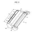
- FIG. 3 is a perspective view illustrating an appearance configuration of the developing unit
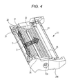
- FIG. 4 is a perspective view illustrating an internal configuration of the developing unit
- FIG. 5 is a sectional view illustrating an internal configuration of the developing unit
- FIG. 6A is a perspective view illustrating an appearance of a paddle
- FIG. 6B is a perspective view illustrating the appearance of the paddle when viewed from a side on which a fin is formed.
- An image forming apparatus 1 illustrated in FIG. 1 is a printer provided with an electrophotographic image recording unit.
- the image forming apparatus 1 may be configured as a copying machine or a facsimile apparatus, in which an image reading unit is added to the image recording unit, and what is called a multifunction peripheral in which the copying machine and a facsimile apparatus are combined.
- a supply unit 2 that supplies a recording sheet (plain paper) is provided in a lower portion, and an electrophotographic image forming unit 7 and a paper discharge unit that discharges the already-recorded recording sheet are provided above the supply unit 2.
- the stacked recording sheets are stored in the supply unit 2, and a pick-up roller 3 and a retard roller 4 feeds the recording sheet one by one.
- the fed recording sheet is introduced to a feed path 6, and a feed roller 5 further delivers the recording sheet onto a downstream side.
- the image forming unit 7 is disposed on the feed path 6, and the image forming unit 7 forms a toner image on the recording sheet and delivers the recording sheet to a fuser unit 8.
- a heat roller 8a and a press roller 8b, which constitute the fuser unit 8, provide heat and a pressure to the recording sheet to fix the toner image onto the recording sheet.
- An exit roller 9 discharges the recording sheet to a paper exit tray 10, thereby ending the process of forming the image on the recording sheet.
- a photosensitive drum 10 (corresponding to an image bearing body) is provided in the image forming unit 7, and the photosensitive drum 10 rotates counterclockwise (see an arrow) during the image formation.
- a charger unit 11, an exposure unit 12, a developing unit 20, and a transfer roller 13 are disposed along a rotating direction of the photosensitive drum 10. The surface of the photosensitive drum 10 is exposed by the exposure unit 12 after charged by the charger unit 11, thereby a latent image is formed on the surface of the photosensitive drum 10. Then the developing unit 20 visualizes the latent image with the toner.
- a toner cartridge 30 is provided adjacent to the developing unit 20.
- FIG. 2 is a perspective view illustrating an appearance in a state in which the developing unit 20 and the toner cartridge 30 are coupled.
- FIG. 3 is a perspective view illustrating an appearance configuration of the developing unit 20.
- FIG. 4 is a perspective view illustrating an internal configuration of the developing unit 20.
- FIG. 5 is a sectional view illustrating the internal configuration of the developing unit.
- FIGS. 6A and 6B are perspective views illustrating an appearance of a paddle.
- non-magnetic monocomponent toner (hereinafter simply referred to as toner) is stored as a developer in a casing 200.
- a casing cover 201 is attached onto an upper side of the casing 200.
- Supply toner is stored in the toner cartridge 30, and the toner cartridge 30 is disposed adjacent to the developing unit 20 in a horizontal direction.
- a feed opening 202 through which the toner is supplied from the toner cartridge 30 is provided as illustrated in FIG. 3 .
- an opening length L1 in a longitudinal direction of the feed opening 202 is set to 1/4 to 1/2 of a total length L2.
- the opening length L1 is set to about 1/3 of the total length L2.
- the feed opening 202 is located in a central portion in the longitudinal direction.
- a shutter member 203 is provided in the feed opening 202, and usually the shutter member 203 is closed before the toner cartridge 30 is attached. When the toner cartridge 30 is attached along a slide rail 204 provided on the side of the developing unit 20, the shutter member 203 moves to open the feed opening 202.
- a first paddle 21, a second paddle 22, a supply roller 23, and a developing roller 24 are rotatably attached in the developing unit 20.
- the outer surface of the supply roller 23 is constructed by a foamed member or a brush to supply the toner to the surface of the developing roller 24.
- the outer surface of the developing roller 24 is disposed while being in contact with the outer surface of the photosensitive drum 10, or the outer surface of the outer surface of the developing roller 24 is disposed while separated from the outer surface of the photosensitive drum 10 with a slight gap.
- the supply roller 23 rotates in a clockwise direction of FIG. 5 , and supplies the toner to the surface of the developing roller 24 that rotates in the clockwise direction of FIG. 5 .
- a leading end of a blade 25 having flexibility is in contact with the surface of the developing roller 24, the blade 25 makes an adjustment such that the toner on the surface of the developing roller 24 becomes a thin film having an even thickness.
- the latent image formed on the surface of the photosensitive drum 10 is visualized to form the toner image.
- the residual toner that does not contribute to the formation of the toner image is returned to and recovered by the developing unit 20.
- a cleaner may separately be provided to remove the toner remaining on the surface of the photosensitive drum 10.
- FIG. 6A is the perspective view illustrating the appearance of the first paddle 21
- FIG. 6B is the perspective view illustrating the appearance of the first paddle 21 when viewed from the side on which the fin is formed.
- the first paddle 21 includes a rotary shaft 21a, and ribs 21b extend radially around the rotary shaft 21a.
- Support discs 21d are provided in both end portions in the longitudinal direction of the rib 21b, and the rotary shaft 21a is provided out of the support disc 21d.
- An attaching rib 21c is longitudinally formed in a circumferential portion of the first paddle 21 in order to attach a film 26.
- the film 26 is a resin sheet.
- Fins 21e are formed in a central portion of the attaching rib 21c.
- the two fins 21e are formed in the central portion of the attaching rib 21c toward both end portions.
- the first paddle 21 rotates in the direction of an arrow A to diffuse the toner in the direction of an arrow B.
- the toner supplied from the feed opening 202 in the central portion is diffused to both end portions in an axial direction of the first paddle 21, which allows the toner to be evenly dispersed.
- the rotary shaft 21a, the rib 21b, the attaching rib 21c, the support disc 21d, and the fin 21e of the first paddle 21 are formed by monolithic molding using a resin. More than two fins may be provided instead of tow fins 21e illustrated in FIG. 6 .
- a rotary shaft 22a of the second paddle 22 is exposed from the casing 200 and coupled to a drive mechanism (not illustrated).
- the drive mechanism including a gear is provided in the casing 200 such that the first paddle 21, the supply roller 23, and the developing roller 24 rotate while interlocking with the rotation of the second paddle 22.
- a scraper 27 is provided in an end portion in an axial direction of the first paddle 21 and has a function of cleaning a transparent detected unit 28.
- a toner sensor is provided out of the casing 200 in order to detect the existence or non-existence of the toner.
- the scraper 27 and the first paddle 21 rotate integrally, and the scraper 27 cleans the detected unit 28, whereby the toner sensor correctly detects the toner.
- a relationship between the radii r and R is set to 0.6R ⁇ r ⁇ 0.8R.
- a toner feeding power is decreased when R - r is excessively large.
- R - r is excessively small, damage to the toner is increased, and a rotary torque of the first paddle 21 is increased.
- a mechanism is provided in the toner cartridge 30 so as to agitate and feed the toner, thereby supplying the toner from the feed opening 202 in proper timing.
- the toner is diffused in a direction of an arrow D (a direction of a rotary axis) while fed in a direction of an arrow C. Therefore, the uneven distribution of the toner can be eliminated.
- the toner cartridge 30 is disposed adjacent to the developing unit 20 in a horizontal direction.
- the disposition of the toner cartridge 30 is not limited to the horizontal direction, but the toner cartridge 30 may be disposed above the developing unit 20.
- the fin that is of the toner guide and the paddle are formed by the monolithic molding.
- the fin may be attached to the main body of the paddle while separately formed.
Landscapes
- Physics & Mathematics (AREA)
- General Physics & Mathematics (AREA)
- Dry Development In Electrophotography (AREA)
Abstract
Description
- The present invention relates to an image forming apparatus provided with a developing unit that includes a feed opening through which toner is supplied from a toner cartridge and visualizes a latent image formed on a photosensitive drum in order to form a toner image.
- In the developing unit provided in the image forming apparatus, after the toner stored in the developing unit is decreased, the toner is supplied to the developing unit from the toner cartridge. For example, in Japanese Patent Publication Laid-Open No.
2009-86505 2010-128250 - A paddle that agitates the supplied toner to feed the toner in a direction of a photosensitive drum is provided in the developing unit. The paddle is configured to rotate about a rotary axis. In Japanese Patent Publication Laid-Open No.
2009-86505 - On the other hand, in Japanese Patent Publication Laid-Open No.
2010-128250 - It is an object of the present invention to provide an image forming apparatus that can evenly diffuse the toner while the opening length of the feed opening is suppressed.
- This object is achieved by an image forming apparatus according to claim 1.
- Other than in the prior art, embodiments of the invention allow for evenly diffusing the toner and an even density in the formed image, while maintaining the strength of a casing of the device. In the device of Japanese Patent Publication Laid-Open No.
2009-86505 2010-128250 - In order to overcome the problems described above, a preferred embodiment of the present invention is an image forming apparatus including: a toner cartridge; a feed opening through which toner is supplied from the toner cartridge; and a developing unit that forms a toner image by visualizing a latent image formed on a photosensitive drum, wherein the developing unit includes a paddle that agitates the toner supplied through the feed opening and feeds the toner in a direction of the photosensitive drum, the feed opening having an opening length shorter than a length in a direction of a rotary axis of the paddle, and the paddle including a toner guide that diffuses the toner in the direction of the rotary axis of the paddle.
- A working effect of the image forming apparatus having the above configuration will be described. In the developing unit provided in the image forming apparatus, the opening length of the feed opening is set shorter than the length in the direction of the rotary axis of the paddle. The toner supplied through the feed opening is agitated and fed by the rotation of the paddle. At this point, the paddle includes the toner guide that diffuses the toner in the direction of the rotary axis of the paddle. The toner supplied through the feed opening is also diffused toward both the end portions in the direction of the rotary axis, so that the uneven distribution of the toner can be eliminated. As a result, the toner can evenly be diffused while the opening length of the feed opening is suppressed.
- Preferably the toner guide is a fin. When the toner guide is formed into the fin shape, the toner guide and the paddle can integrally be formed, and a new function can be added while cost is suppressed.
- Preferably the feed opening is opened upward, the toner in the toner cartridge drops through the feed opening, and the toner is supplied to the developing unit.
- Accordingly, the toner is caused to drop from above, so that the toner can be supplied into developing unit by a simple configuration.
- Preferably the feed opening according to the present invention is disposed in a central portion in the direction of the rotary axis of the paddle, and the toner guide diffuses the toner toward both end portions in the direction of the rotary axis.
- Accordingly, the feed opening is disposed in the central portion in the direction of the rotary axis, and the toner is diffused from the central portion toward both the end portions (one end portion and the other end portion) of an axial direction. The toner is substantially evenly diffused toward one end portion and the other end portion, so that the toner can evenly be distributed.
-
FIG. 1 is a sectional view conceptually illustrating an internal configuration of an image forming apparatus; -
FIG. 2 is a perspective view illustrating an appearance in a state in which a developing unit and a toner cartridge are coupled; -
FIG. 3 is a perspective view illustrating an appearance configuration of the developing unit; -
FIG. 4 is a perspective view illustrating an internal configuration of the developing unit; -
FIG. 5 is a sectional view illustrating an internal configuration of the developing unit; -
FIG. 6A is a perspective view illustrating an appearance of a paddle; and -
FIG. 6B is a perspective view illustrating the appearance of the paddle when viewed from a side on which a fin is formed. - An image forming apparatus according to an embodiment of the invention will be described below with reference to the drawings. An image forming apparatus 1 illustrated in
FIG. 1 is a printer provided with an electrophotographic image recording unit. Alternatively, the image forming apparatus 1 may be configured as a copying machine or a facsimile apparatus, in which an image reading unit is added to the image recording unit, and what is called a multifunction peripheral in which the copying machine and a facsimile apparatus are combined. In the image forming apparatus 1 ofFIG. 1 , a supply unit 2 that supplies a recording sheet (plain paper) is provided in a lower portion, and an electrophotographic image forming unit 7 and a paper discharge unit that discharges the already-recorded recording sheet are provided above the supply unit 2. - The stacked recording sheets are stored in the supply unit 2, and a pick-
up roller 3 and a retard roller 4 feeds the recording sheet one by one. The fed recording sheet is introduced to a feed path 6, and afeed roller 5 further delivers the recording sheet onto a downstream side. The image forming unit 7 is disposed on the feed path 6, and the image forming unit 7 forms a toner image on the recording sheet and delivers the recording sheet to afuser unit 8. Aheat roller 8a and apress roller 8b, which constitute thefuser unit 8, provide heat and a pressure to the recording sheet to fix the toner image onto the recording sheet. An exit roller 9 discharges the recording sheet to apaper exit tray 10, thereby ending the process of forming the image on the recording sheet. - The image forming unit 7 will be described below. A photosensitive drum 10 (corresponding to an image bearing body) is provided in the image forming unit 7, and the
photosensitive drum 10 rotates counterclockwise (see an arrow) during the image formation. Acharger unit 11, anexposure unit 12, a developingunit 20, and atransfer roller 13 are disposed along a rotating direction of thephotosensitive drum 10. The surface of thephotosensitive drum 10 is exposed by theexposure unit 12 after charged by thecharger unit 11, thereby a latent image is formed on the surface of thephotosensitive drum 10. Then the developingunit 20 visualizes the latent image with the toner. When the recording sheet reaches a nip position between thetransfer roller 13 and thephotosensitive drum 10, a bias voltage is applied to thetransfer roller 13, and the toner image on the outer surface of thephotosensitive drum 10 is electrically attracted to the recording sheet. Therefore, the image is formed on the recording sheet. Atoner cartridge 30 is provided adjacent to the developingunit 20. - A configuration of the developing
unit 20 will be described below.FIG. 2 is a perspective view illustrating an appearance in a state in which the developingunit 20 and thetoner cartridge 30 are coupled.FIG. 3 is a perspective view illustrating an appearance configuration of the developingunit 20.FIG. 4 is a perspective view illustrating an internal configuration of the developingunit 20.FIG. 5 is a sectional view illustrating the internal configuration of the developing unit.FIGS. 6A and 6B are perspective views illustrating an appearance of a paddle. - In the developing
unit 20, non-magnetic monocomponent toner (hereinafter simply referred to as toner) is stored as a developer in acasing 200. Acasing cover 201 is attached onto an upper side of thecasing 200. Supply toner is stored in thetoner cartridge 30, and thetoner cartridge 30 is disposed adjacent to the developingunit 20 in a horizontal direction. - A
feed opening 202 through which the toner is supplied from thetoner cartridge 30 is provided as illustrated inFIG. 3 . Preferably an opening length L1 in a longitudinal direction of thefeed opening 202 is set to 1/4 to 1/2 of a total length L2. In the embodiment, the opening length L1 is set to about 1/3 of the total length L2. Thefeed opening 202 is located in a central portion in the longitudinal direction. Ashutter member 203 is provided in thefeed opening 202, and usually theshutter member 203 is closed before thetoner cartridge 30 is attached. When thetoner cartridge 30 is attached along aslide rail 204 provided on the side of the developingunit 20, theshutter member 203 moves to open thefeed opening 202. - As illustrated in
FIG. 5 , afirst paddle 21, asecond paddle 22, asupply roller 23, and a developingroller 24 are rotatably attached in the developingunit 20. The outer surface of thesupply roller 23 is constructed by a foamed member or a brush to supply the toner to the surface of the developingroller 24. The outer surface of the developingroller 24 is disposed while being in contact with the outer surface of thephotosensitive drum 10, or the outer surface of the outer surface of the developingroller 24 is disposed while separated from the outer surface of thephotosensitive drum 10 with a slight gap. - The
supply roller 23 rotates in a clockwise direction ofFIG. 5 , and supplies the toner to the surface of the developingroller 24 that rotates in the clockwise direction ofFIG. 5 . A leading end of ablade 25 having flexibility is in contact with the surface of the developingroller 24, theblade 25 makes an adjustment such that the toner on the surface of the developingroller 24 becomes a thin film having an even thickness. Using the thin film of the toner formed on the surface of the developingroller 24, the latent image formed on the surface of thephotosensitive drum 10 is visualized to form the toner image. The residual toner that does not contribute to the formation of the toner image is returned to and recovered by the developingunit 20. Alternatively, a cleaner may separately be provided to remove the toner remaining on the surface of thephotosensitive drum 10. - Because the
first paddle 21 and thesecond paddle 22 basically have the same shape, only thefirst paddle 21 will be described. When thefirst paddle 21 can sufficiently rotate the toner, a fin may not be provided in thesecond paddle 22.FIG. 6A is the perspective view illustrating the appearance of thefirst paddle 21, andFIG. 6B is the perspective view illustrating the appearance of thefirst paddle 21 when viewed from the side on which the fin is formed. - The
first paddle 21 includes arotary shaft 21a, andribs 21b extend radially around therotary shaft 21a.Support discs 21d are provided in both end portions in the longitudinal direction of therib 21b, and therotary shaft 21a is provided out of thesupport disc 21d. An attachingrib 21c is longitudinally formed in a circumferential portion of thefirst paddle 21 in order to attach afilm 26. Thefilm 26 is a resin sheet. When thefirst paddle 21 rotates, thefilm 26 delivers the toner in a direction of thephotosensitive drum 10. -
Fins 21e are formed in a central portion of the attachingrib 21c. The twofins 21e are formed in the central portion of the attachingrib 21c toward both end portions. As illustrated inFIG. 6B , thefirst paddle 21 rotates in the direction of an arrow A to diffuse the toner in the direction of an arrow B. The toner supplied from thefeed opening 202 in the central portion is diffused to both end portions in an axial direction of thefirst paddle 21, which allows the toner to be evenly dispersed. - The
rotary shaft 21a, therib 21b, the attachingrib 21c, thesupport disc 21d, and thefin 21e of thefirst paddle 21 are formed by monolithic molding using a resin. More than two fins may be provided instead oftow fins 21e illustrated inFIG. 6 . - As illustrated in
FIG. 4 , arotary shaft 22a of thesecond paddle 22 is exposed from thecasing 200 and coupled to a drive mechanism (not illustrated). The drive mechanism including a gear is provided in thecasing 200 such that thefirst paddle 21, thesupply roller 23, and the developingroller 24 rotate while interlocking with the rotation of thesecond paddle 22. - A
scraper 27 is provided in an end portion in an axial direction of thefirst paddle 21 and has a function of cleaning a transparent detectedunit 28. A toner sensor is provided out of thecasing 200 in order to detect the existence or non-existence of the toner. Thescraper 27 and thefirst paddle 21 rotate integrally, and thescraper 27 cleans the detectedunit 28, whereby the toner sensor correctly detects the toner. - As illustrated in
FIG. 5 , assuming that r is a radius of thefin 21e of thefirst paddle 21 and R is a radius of an inner wall surface of thecasing 200 to which thefirst paddle 21 is attached, preferably a relationship between the radii r and R is set to 0.6R ≤ r ≤ 0.8R. A toner feeding power is decreased when R - r is excessively large. When R - r is excessively small, damage to the toner is increased, and a rotary torque of thefirst paddle 21 is increased. - Although not illustrated, a mechanism is provided in the
toner cartridge 30 so as to agitate and feed the toner, thereby supplying the toner from thefeed opening 202 in proper timing. As illustrated inFIG. 4 , when thefirst paddle 21 and thesecond paddle 22 rotate, the toner is diffused in a direction of an arrow D (a direction of a rotary axis) while fed in a direction of an arrow C. Therefore, the uneven distribution of the toner can be eliminated. - In the embodiment, the
toner cartridge 30 is disposed adjacent to the developingunit 20 in a horizontal direction. The disposition of thetoner cartridge 30 is not limited to the horizontal direction, but thetoner cartridge 30 may be disposed above the developingunit 20. - In the embodiment, the fin that is of the toner guide and the paddle are formed by the monolithic molding. Alternatively, the fin may be attached to the main body of the paddle while separately formed.
Claims (6)
- An image forming apparatus comprising:a toner cartridge (30);a feed opening (202) through which toner is supplied from the toner cartridge (30); anda developing unit (20) adapted to form a toner image by visualizing a latent image formed on a photosensitive drum (10),characterized in thatthe developing unit (20) includes a paddle (21) adapted to agitate the toner supplied through the feed opening (202) and adapted to feed the toner in a direction of the photosensitive drum (10),the feed opening (202) has an opening length shorter than a length in a direction of a rotary axis of the paddle (21), andthe paddle (21) includes a toner guide (21e) adapted to diffuse the toner in the direction of the rotary axis of the paddle (21) .
- The image forming apparatus according to claim 1, characterized in that the toner guide (21e) is a fin.
- The image forming apparatus according to claim 2, characterized in that the fin and the paddle (21) are formed by monolithic molding.
- The image forming apparatus according to claim 2 or 3, characterized in that the following relationship is satisfied:

where r is a radius of the fin and R is a radius of an inner wall surface of a casing of the developing unit (20). - The image forming apparatus as in any one of claims 1 to 4, characterized in that the feed opening (202) is opened upward, the toner in the toner cartridge (30) is adapted to drop in the developing unit (20) through the feed opening to be supplied from the toner cartridge (30) to the developing unit (20).
- The image forming apparatus as in any one of claims 1 to 5, characterized in that the feed opening (202) is disposed in a central portion in the direction of the rotary axis of the paddle (21), and
the toner guide (21e) is adapted to diffuse the toner toward both end portions in the direction (D) of the rotary axis.
Applications Claiming Priority (2)
| Application Number | Priority Date | Filing Date | Title |
|---|---|---|---|
| JP2010247533 | 2010-11-04 | ||
| JP2011128202A JP2012113278A (en) | 2010-11-04 | 2011-06-08 | Image forming apparatus |
Publications (2)
| Publication Number | Publication Date |
|---|---|
| EP2455818A2 true EP2455818A2 (en) | 2012-05-23 |
| EP2455818A3 EP2455818A3 (en) | 2016-08-17 |
Family
ID=44872225
Family Applications (1)
| Application Number | Title | Priority Date | Filing Date |
|---|---|---|---|
| EP11186154.8A Withdrawn EP2455818A3 (en) | 2010-11-04 | 2011-10-21 | Image forming apparatus |
Country Status (5)
| Country | Link |
|---|---|
| US (1) | US8682225B2 (en) |
| EP (1) | EP2455818A3 (en) |
| JP (1) | JP2012113278A (en) |
| KR (1) | KR20120047768A (en) |
| CN (2) | CN102467024A (en) |
Families Citing this family (4)
| Publication number | Priority date | Publication date | Assignee | Title |
|---|---|---|---|---|
| JP2012113278A (en) * | 2010-11-04 | 2012-06-14 | Murata Mach Ltd | Image forming apparatus |
| JP5868438B2 (en) * | 2014-01-27 | 2016-02-24 | シャープ株式会社 | Toner cartridge and image forming apparatus having the same |
| JP6525633B2 (en) * | 2015-02-24 | 2019-06-05 | キヤノン株式会社 | Developing device, process cartridge and image forming apparatus |
| JP6598572B2 (en) * | 2015-08-12 | 2019-10-30 | 株式会社東芝 | Developer supply container |
Citations (2)
| Publication number | Priority date | Publication date | Assignee | Title |
|---|---|---|---|---|
| JP2009086505A (en) | 2007-10-02 | 2009-04-23 | Brother Ind Ltd | Developer cartridge, developing device, process cartridge, and image forming apparatus |
| JP2010128250A (en) | 2008-11-28 | 2010-06-10 | Murata Machinery Ltd | Developing unit |
Family Cites Families (8)
| Publication number | Priority date | Publication date | Assignee | Title |
|---|---|---|---|---|
| US4878088A (en) * | 1985-07-02 | 1989-10-31 | Fujitsu Limited | Developing unit of electrophotographic apparatus |
| JPH058610Y2 (en) * | 1986-11-18 | 1993-03-03 | ||
| JPH06348124A (en) * | 1993-06-02 | 1994-12-22 | Ricoh Co Ltd | Development device |
| US5867756A (en) | 1996-05-27 | 1999-02-02 | Brother Kogyo Kabushiki Kaisha | Developing device with an auger roller for providing a fresh and consistent stream of developer in an image forming apparatus |
| JP3598655B2 (en) | 1996-05-27 | 2004-12-08 | ブラザー工業株式会社 | Developing device in image forming apparatus |
| US6526245B1 (en) * | 2000-08-29 | 2003-02-25 | Toshiba Tec Kabushiki Kaisha | Image forming apparatus |
| US7409170B2 (en) * | 2006-03-23 | 2008-08-05 | Kabushiki Kaisha Toshiba | Developing apparatus, image forming apparatus and density detection method |
| JP2012113278A (en) * | 2010-11-04 | 2012-06-14 | Murata Mach Ltd | Image forming apparatus |
-
2011
- 2011-06-08 JP JP2011128202A patent/JP2012113278A/en active Pending
- 2011-10-11 KR KR1020110103532A patent/KR20120047768A/en not_active Withdrawn
- 2011-10-13 US US13/272,722 patent/US8682225B2/en not_active Expired - Fee Related
- 2011-10-14 CN CN2011103198932A patent/CN102467024A/en active Pending
- 2011-10-14 CN CN2011203990819U patent/CN202583700U/en not_active Expired - Fee Related
- 2011-10-21 EP EP11186154.8A patent/EP2455818A3/en not_active Withdrawn
Patent Citations (2)
| Publication number | Priority date | Publication date | Assignee | Title |
|---|---|---|---|---|
| JP2009086505A (en) | 2007-10-02 | 2009-04-23 | Brother Ind Ltd | Developer cartridge, developing device, process cartridge, and image forming apparatus |
| JP2010128250A (en) | 2008-11-28 | 2010-06-10 | Murata Machinery Ltd | Developing unit |
Also Published As
| Publication number | Publication date |
|---|---|
| US20120114384A1 (en) | 2012-05-10 |
| CN202583700U (en) | 2012-12-05 |
| US8682225B2 (en) | 2014-03-25 |
| CN102467024A (en) | 2012-05-23 |
| EP2455818A3 (en) | 2016-08-17 |
| KR20120047768A (en) | 2012-05-14 |
| JP2012113278A (en) | 2012-06-14 |
Similar Documents
| Publication | Publication Date | Title |
|---|---|---|
| US8131183B2 (en) | Developer collection container, developer cartridge, developing unit and image forming apparatus | |
| JP5184660B2 (en) | Developing device and image forming apparatus | |
| JP5061226B2 (en) | Developing device and image forming apparatus | |
| CN1983058A (en) | Image developing apparatus and image forming apparatus using the same | |
| US8682225B2 (en) | Image forming apparatus with paddle that agitates toner supplied through feed opening | |
| US20120128391A1 (en) | Developer collection container and image formation apparatus | |
| JP5065456B2 (en) | Toner cartridge and image forming apparatus having the same | |
| US9122197B2 (en) | Developer storage body, image forming unit and image forming apparatus | |
| JP5877079B2 (en) | Developing device and image forming apparatus | |
| US8953976B2 (en) | Developing device, image forming apparatus, and process cartridge | |
| US7088943B2 (en) | Image forming apparatus, apparatus for supplying toner and developing apparatus using therefor | |
| JP2006251213A (en) | Developing device | |
| JP6047321B2 (en) | Developing device and image forming apparatus | |
| JP5074869B2 (en) | Development device | |
| EP2942671B1 (en) | Developing unit, image forming unit, and image forming apparatus | |
| US8515320B2 (en) | Developing device, process unit and image forming apparatus | |
| JP2007256441A (en) | Developing device | |
| JP4339278B2 (en) | Developing device and image forming apparatus to which the developing device is applied | |
| JP7619913B2 (en) | Developing device and image forming apparatus | |
| JP6618740B2 (en) | Conveying device, developing device, and image forming apparatus | |
| JP5985274B2 (en) | Developing device and image forming apparatus | |
| US7590370B2 (en) | Image forming apparatus having openings and a cover | |
| JP5600560B2 (en) | Developing device and image forming apparatus | |
| JP2005215438A (en) | Toner supply device for image forming apparatus | |
| JP5332385B2 (en) | Developing device, process cartridge, and image forming apparatus |
Legal Events
| Date | Code | Title | Description |
|---|---|---|---|
| PUAI | Public reference made under article 153(3) epc to a published international application that has entered the european phase |
Free format text: ORIGINAL CODE: 0009012 |
|
| AK | Designated contracting states |
Kind code of ref document: A2 Designated state(s): AL AT BE BG CH CY CZ DE DK EE ES FI FR GB GR HR HU IE IS IT LI LT LU LV MC MK MT NL NO PL PT RO RS SE SI SK SM TR |
|
| AX | Request for extension of the european patent |
Extension state: BA ME |
|
| PUAL | Search report despatched |
Free format text: ORIGINAL CODE: 0009013 |
|
| AK | Designated contracting states |
Kind code of ref document: A3 Designated state(s): AL AT BE BG CH CY CZ DE DK EE ES FI FR GB GR HR HU IE IS IT LI LT LU LV MC MK MT NL NO PL PT RO RS SE SI SK SM TR |
|
| AX | Request for extension of the european patent |
Extension state: BA ME |
|
| RIC1 | Information provided on ipc code assigned before grant |
Ipc: G03G 15/08 20060101AFI20160714BHEP |
|
| RIN1 | Information on inventor provided before grant (corrected) |
Inventor name: TAKAMATSU, NARITOSHI |
|
| STAA | Information on the status of an ep patent application or granted ep patent |
Free format text: STATUS: THE APPLICATION HAS BEEN WITHDRAWN |
|
| 18W | Application withdrawn |
Effective date: 20160906 |