EP2455727A1 - Separator for light density material - Google Patents
Separator for light density material Download PDFInfo
- Publication number
- EP2455727A1 EP2455727A1 EP11174896A EP11174896A EP2455727A1 EP 2455727 A1 EP2455727 A1 EP 2455727A1 EP 11174896 A EP11174896 A EP 11174896A EP 11174896 A EP11174896 A EP 11174896A EP 2455727 A1 EP2455727 A1 EP 2455727A1
- Authority
- EP
- European Patent Office
- Prior art keywords
- sensor
- flooding
- container
- dip tube
- ultrasonic
- Prior art date
- Legal status (The legal status is an assumption and is not a legal conclusion. Google has not performed a legal analysis and makes no representation as to the accuracy of the status listed.)
- Granted
Links
- 239000000463 material Substances 0.000 title description 7
- 239000007788 liquid Substances 0.000 claims abstract description 29
- 239000003562 lightweight material Substances 0.000 claims description 22
- 238000005538 encapsulation Methods 0.000 claims description 15
- 238000011156 evaluation Methods 0.000 claims description 10
- 238000004880 explosion Methods 0.000 claims description 8
- 238000009434 installation Methods 0.000 claims description 6
- 238000007667 floating Methods 0.000 claims description 3
- 238000005259 measurement Methods 0.000 description 14
- 238000002604 ultrasonography Methods 0.000 description 13
- 239000004519 grease Substances 0.000 description 9
- 230000005540 biological transmission Effects 0.000 description 5
- 230000008021 deposition Effects 0.000 description 5
- 238000007654 immersion Methods 0.000 description 4
- 238000000926 separation method Methods 0.000 description 4
- 239000004593 Epoxy Substances 0.000 description 3
- 238000013461 design Methods 0.000 description 3
- 238000001514 detection method Methods 0.000 description 3
- 238000012423 maintenance Methods 0.000 description 3
- 239000000126 substance Substances 0.000 description 3
- 238000012544 monitoring process Methods 0.000 description 2
- 230000001105 regulatory effect Effects 0.000 description 2
- 238000007789 sealing Methods 0.000 description 2
- 239000010802 sludge Substances 0.000 description 2
- 238000005266 casting Methods 0.000 description 1
- 238000004200 deflagration Methods 0.000 description 1
- 230000001419 dependent effect Effects 0.000 description 1
- 238000011161 development Methods 0.000 description 1
- 230000009977 dual effect Effects 0.000 description 1
- 230000008030 elimination Effects 0.000 description 1
- 238000003379 elimination reaction Methods 0.000 description 1
- 238000005265 energy consumption Methods 0.000 description 1
- 238000005516 engineering process Methods 0.000 description 1
- 239000012530 fluid Substances 0.000 description 1
- 239000007789 gas Substances 0.000 description 1
- 210000004907 gland Anatomy 0.000 description 1
- 239000004615 ingredient Substances 0.000 description 1
- 230000002045 lasting effect Effects 0.000 description 1
- 230000007257 malfunction Effects 0.000 description 1
- 238000004519 manufacturing process Methods 0.000 description 1
- 238000000034 method Methods 0.000 description 1
- 238000010137 moulding (plastic) Methods 0.000 description 1
- 239000012716 precipitator Substances 0.000 description 1
- 230000002035 prolonged effect Effects 0.000 description 1
- 229920005989 resin Polymers 0.000 description 1
- 239000011347 resin Substances 0.000 description 1
- 238000009420 retrofitting Methods 0.000 description 1
- 229920003002 synthetic resin Polymers 0.000 description 1
- 239000000057 synthetic resin Substances 0.000 description 1
- 239000002351 wastewater Substances 0.000 description 1
Images

Classifications
-
- G—PHYSICS
- G01—MEASURING; TESTING
- G01F—MEASURING VOLUME, VOLUME FLOW, MASS FLOW OR LIQUID LEVEL; METERING BY VOLUME
- G01F23/00—Indicating or measuring liquid level or level of fluent solid material, e.g. indicating in terms of volume or indicating by means of an alarm
- G01F23/22—Indicating or measuring liquid level or level of fluent solid material, e.g. indicating in terms of volume or indicating by means of an alarm by measuring physical variables, other than linear dimensions, pressure or weight, dependent on the level to be measured, e.g. by difference of heat transfer of steam or water
- G01F23/28—Indicating or measuring liquid level or level of fluent solid material, e.g. indicating in terms of volume or indicating by means of an alarm by measuring physical variables, other than linear dimensions, pressure or weight, dependent on the level to be measured, e.g. by difference of heat transfer of steam or water by measuring the variations of parameters of electromagnetic or acoustic waves applied directly to the liquid or fluent solid material
- G01F23/296—Acoustic waves
- G01F23/2961—Acoustic waves for discrete levels
-
- B—PERFORMING OPERATIONS; TRANSPORTING
- B01—PHYSICAL OR CHEMICAL PROCESSES OR APPARATUS IN GENERAL
- B01D—SEPARATION
- B01D17/00—Separation of liquids, not provided for elsewhere, e.g. by thermal diffusion
- B01D17/02—Separation of non-miscible liquids
- B01D17/0208—Separation of non-miscible liquids by sedimentation
- B01D17/0211—Separation of non-miscible liquids by sedimentation with baffles
-
- B—PERFORMING OPERATIONS; TRANSPORTING
- B01—PHYSICAL OR CHEMICAL PROCESSES OR APPARATUS IN GENERAL
- B01D—SEPARATION
- B01D17/00—Separation of liquids, not provided for elsewhere, e.g. by thermal diffusion
- B01D17/12—Auxiliary equipment particularly adapted for use with liquid-separating apparatus, e.g. control circuits
-
- G—PHYSICS
- G01—MEASURING; TESTING
- G01F—MEASURING VOLUME, VOLUME FLOW, MASS FLOW OR LIQUID LEVEL; METERING BY VOLUME
- G01F23/00—Indicating or measuring liquid level or level of fluent solid material, e.g. indicating in terms of volume or indicating by means of an alarm
- G01F23/22—Indicating or measuring liquid level or level of fluent solid material, e.g. indicating in terms of volume or indicating by means of an alarm by measuring physical variables, other than linear dimensions, pressure or weight, dependent on the level to be measured, e.g. by difference of heat transfer of steam or water
- G01F23/28—Indicating or measuring liquid level or level of fluent solid material, e.g. indicating in terms of volume or indicating by means of an alarm by measuring physical variables, other than linear dimensions, pressure or weight, dependent on the level to be measured, e.g. by difference of heat transfer of steam or water by measuring the variations of parameters of electromagnetic or acoustic waves applied directly to the liquid or fluent solid material
- G01F23/296—Acoustic waves
- G01F23/2962—Measuring transit time of reflected waves
-
- C—CHEMISTRY; METALLURGY
- C02—TREATMENT OF WATER, WASTE WATER, SEWAGE, OR SLUDGE
- C02F—TREATMENT OF WATER, WASTE WATER, SEWAGE, OR SLUDGE
- C02F1/00—Treatment of water, waste water, or sewage
- C02F1/40—Devices for separating or removing fatty or oily substances or similar floating material
-
- C—CHEMISTRY; METALLURGY
- C02—TREATMENT OF WATER, WASTE WATER, SEWAGE, OR SLUDGE
- C02F—TREATMENT OF WATER, WASTE WATER, SEWAGE, OR SLUDGE
- C02F2101/00—Nature of the contaminant
- C02F2101/30—Organic compounds
- C02F2101/32—Hydrocarbons, e.g. oil
-
- C—CHEMISTRY; METALLURGY
- C02—TREATMENT OF WATER, WASTE WATER, SEWAGE, OR SLUDGE
- C02F—TREATMENT OF WATER, WASTE WATER, SEWAGE, OR SLUDGE
- C02F2209/00—Controlling or monitoring parameters in water treatment
- C02F2209/42—Liquid level
-
- E—FIXED CONSTRUCTIONS
- E03—WATER SUPPLY; SEWERAGE
- E03F—SEWERS; CESSPOOLS
- E03F5/00—Sewerage structures
- E03F5/14—Devices for separating liquid or solid substances from sewage, e.g. sand or sludge traps, rakes or grates
- E03F5/16—Devices for separating oil, water or grease from sewage in drains leading to the main sewer
Definitions
- the invention relates to a lightweight material separator according to the preamble of patent claim 1.
- flooding In light-weight separators, such as gasoline, oil or grease traps, it has been known for decades to detect flooding by means of a flood sensor and display in order to be able to initiate or plan countermeasures in a timely manner. Flooding may occur due to backlog or other reasons, such as failure or improper maintenance or disposal of deposited materials, and increases the operational hazard of the lightweight material deposition plant. In the case of flammable or gassing light-weight deposition equipment, flooding can lead to the risk of explosion or to the release of ingredients and endanger the environment. In the case of grease separators, which, unlike, for example, gasoline separators, are odor-tight, the separation operation can be permanently disrupted. In any case, flooding is the reason for immediate or early countermeasures.
- the known flooding sensors measure the electrical conductivity at the measuring location and provide a signal as soon as the conductivity changes significantly.
- the signal represents the flooding only up to the measuring location.
- the detection of flooding via conductivity measurements requires relatively high effort, and possibly flanking measures on the flooding sensor to ensure its reliable operation for a long time, and is too slow or unreliable in certain operating conditions.
- DE 10 2004 036 645 A relates to an ultrasonic level sensor device with an ultrasonic transducer on a dip tube.
- the ultrasonic transducer is installed near the bottom of a container and measures upward to detect the level or level of at least one interface between layers of different densities.
- the transit time of each ultrasonic pulse which is reflected from the level of the level or the interface to the ultrasonic transducer, and provides a function dependent on the transit time signal. Since different liquids or layers or changes in the composition of the liquids or layers give different transit times, a reflector is arranged for calibration on the dip tube, which has a predetermined distance from the ultrasonic transducer and provides a reference for each measurement, so that each measurement isskalibrierend feasible.
- a monitoring system with multiple ultrasonic transducers for a deposition plant is known.
- the ultrasonic transducers are approximately in the middle of the container Height and installed on the container lid.
- the ultrasonic transducer located at the top has its measuring direction downwards.
- the message signals of the ultrasonic transducers are evaluated so that, for example, distances between boundary surfaces of different layers or the fill level and / or layer thicknesses are determined and displayed.
- the ultrasonic transducer installed above measures with ultrasound pulses in air. Should a flooding occur up to the upper ultrasonic transducer, the ultrasonic transducer is disabled.
- European patent application Az: 09 003 271 recommends a grease trap with a measuring system with ultrasonic transducers for measuring primarily the fat layer thickness, wherein the grease layer thickness is determined based on the example defined by the lower edge of the process operating free-plane over the height of the interface between the liquid and the fat layer. From the height distance between the boundary surface and the operating free-level, the fat layer thickness is calculated by assuming the density of the fat layer assumed to be known, since the layer of grease, part of which is above the operating free-level, further reduces the interface downwards relative to the operating free-level displaced, the thicker the fat layer is. Furthermore, the mud layer thickness or the altitude of the top of a mud layer near the bottom can also be detected.
- the ultrasound sensors are installed in the liquid below the operating free mirror and connected in a signal transmitting manner to a supply and evaluation device arranged outside the container so that records for the deposition operation over the operating period can also be generated via permanent or cyclical operation of the ultrasound sensors.
- the invention has for its object to provide a light-weight separator of the type mentioned above, which is characterized by a simple and above all reliable, very precise flooding sensor.
- the flooding sensor should not only register and report the occurrence of flooding up to the measuring location of the flooding sensor, but also detect the extent and / or the trend of the flooding, at least when a longer lasting flooding occurs.
- An ultrasonic sensor as a flooding sensor provides a very precise message signal in the event of flooding and does not need flanking measures for high-quality measurements. According to the invention, therefore, the ultrasonic sensor is used as a flooding sensor not for distance measurement, but primarily to emit in the presence of a UltraschallImpulse reflecting medium at the measuring location a signal representing the flooding.
- the ultrasonic sensor can be operated with low energy consumption and can be designed with little extra effort so that in the case of flammable or gaseous light materials the regulatory requirements with regard to explosion protection is met.
- the ultrasonic sensor measures with ultrasonic pulses in the air space of the container upwards or to the side and, as long as no flooding takes place, no signal, but only when in case of flooding the ultrasonic sensor of liquid and / or the light material is contacted , Then, the ultrasonic sensor provides a signal representing the flooding. A reverse signal evaluation is also possible.
- the ultrasonic sensor is installed above the operating free-level, conveniently approximately above the middle of the drain or at the level of the upper edge of the drain, or even slightly higher, if appropriate, but not directly on the tank lid.
- the trained as ultrasonic sensor flooding sensor is universally suitable for grease, gasoline separators, gasoline separators or separators other lightweight materials (each with a density ⁇ 1), is inexpensive and extremely reliable.
- the flood sensor used can also detect the extent of flooding.
- the ultrasonic sensor is formed with measurement direction upwards and installed in the air space and in addition to the detection of flooding up to the measurement and the extent of flooding measures and reports. Since the ultrasonic sensor, for example, in contact with air in the air space provides no signal, but only from contact with the liquid or a layer of light material to first register the occurrence of flooding, he can in consequence with increasing flooding from the running time back to the ultrasound Sensor reflected ultrasound pulses measure and indicate the extent of flooding.
- the ultrasonic sensor as a flooding sensor fulfills a multiple function in the detection, with which the operational safety of the lightweight material separator can be improved.
- the very meaningful and promptly generated signals from the ultrasonic sensor provided as a flooding sensor also make it possible to record the operation of the light weight separator to provide additional information to the operator or a maintenance company at what times how often, and how much flooding occurs, for example, to give a guideline to assess whether the design of the lightweight material separator meets local requirements or not, whether or not the feed of the light weight separator should be regulated, ie reduced or increased, or if and when the operator negligently or negligently carries out the maintenance or disposal.
- the ultrasonic sensor is arranged as a flooding sensor on a in the container, preferably from above, installed immersion tube and positioned on the installation of the dip tube itself at the right location.
- the dip tube with the ultrasonic sensor is a prefabricatable original equipment or retrofit part of the lightweight material separator.
- the ultrasonic sensor is arranged on a printed circuit board and encapsulated with the printed circuit board in plastic or poured.
- the encapsulation or encapsulation forms a sensor finger, which is relatively robust.
- the already very low power output for operating the ultrasonic sensor is no reason for the risk of explosion in the case of combustible, separated lightweight materials or gases or vapors released therefrom, because the energy outside the encapsulation or the encapsulation is by far less than the energy required for ignition.
- the ultrasonic sensor can be designed in such a way that the regulations regarding explosion protection are taken into account.
- At least one further ultrasonic sensor for detecting an operating state (level or thickness) of at least one in the container on the bottom side and / or in the container, preferably on the immersion tube to which the ultrasonic sensor acting as a flooding sensor is arranged. or floating deposited layer.
- at least one further intended ultrasound sensor can serve as a reference sensor for self-calibration of the measuring system.
- a reflector reflecting ultrasonic pulses to one of the ultrasonic sensors could also be arranged on the dip tube.
- One of these further ultrasound sensors with measurement direction upwards can be used, for example, for measuring the layer thickness of deposited light substances, while optionally another ultrasound sensor with measurement direction down either forms the reference sensor or is used for layer height or layer thickness measurement of a layer deposited on the bottom side.
- the dip tube serves as a carrier of all ultrasonic sensors, for their positioning in the container, and also for transmitting the signals to the outside to the supply and evaluation.
- the ultrasound sensor which serves either as a reference sensor and / or as a thickness or height measuring sensor for the bottom layer, is located between the ultrasonic sensor serving as a flooding sensor and a lower ultrasonic sensor for measuring the thickness the deposited lightweight material layer placed.
- the sensor fingers are approximately perpendicular to the dip tube.
- the sensor fingers can be placed approximately in a common radial plane of the dip tube, relative to the dip tube axis, wherein, expediently two ultrasound sensors or sensor fingers positioned in the liquid are slightly offset from one another, they are expediently angularly offset by approximately 10 ° to each other, so that not only the referencing, but also the layer thickness or layer height measurements can be performed simultaneously.
- Each sensor finger can be approximately cylindrical and have a flat plane perpendicular to the measuring direction of its ultrasonic sensor to ensure both a directed exit of the ultrasonic pulses and a directed entry of reflected ultrasonic pulses.
- the dip tube is a plastic tube to which a T-tube piece is fixed for holding a sensor finger per ultrasonic sensor, wherein manufacturing technology easy and to turn away from malfunction each sensor finger with a Locking both rotationally secured and sealed in a pipe socket of the T-pipe section can be set, for example, potted with a synthetic resin.
- the ultrasound sensor equipment of the lightweight material separator is thus a conveniently vorfertigbare, outside the container testable and calibratable equipment either for initial equipment or for retrofitting.
- each ultrasonic sensor is connected via a cabling installed in the immersion tube, expediently separately, to a supply and evaluation device arranged outside the container.
- the evaluation device can be placed in a control cabinet or a control station, and optionally have input and display devices.
- the supply and evaluation device can also be connected to the Internet in order to transmit operating information about strategic locations away from the light-weight separator online or to retrieve it from there.
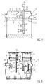
- FIG. 1 schematically shown light-weight separator A as part of an unspecified highlighted deposition system has a container 1 with a top cover 2, a liquid inlet 3 and a deeper liquid drain 4 on the lightweight separator A, a gasoline separator, oil separator or grease trap or separator for others Be lightweight materials with a density ⁇ 1, and expediently also sink or heavy materials on the ground.
- About the liquid inlet 3 is loaded with light and optionally heavies fluid 5, typically wastewater, initiated. From the liquid effluent 4 runs off by separation purified liquid.
- the lower edge of the liquid outlet 4 defines, for example, an operating free-face F, above which there is an air space in the container 1.
- Light substances deposited as layer 6 float in the liquid 5, while separated heavy substances, for example as sludge, are deposited in a layer 7 on the bottom.
- a flooding sensor S is installed, which is designed as an ultrasonic sensor 8 and mounted in a sensor finger 9 on a dip tube 11 and by means of the dip tube 11 or its installation 12 in the closure lid 2 (or alternatively) is installed in the top of the container 1 next to the closure lid 2 from above.
- the ultrasonic sensor 8 is formed, for example, with measuring direction 10 upwards to the closure lid 2.
- the ultrasonic sensor 8 is positioned in the sensor finger 9, for example below the closure lid 2 in the air space and above the liquid outlet 4 and connected via a wiring 13 to a supply and evaluation device 14.
- the ultrasonic sensor 8 generates, for example, in air no message signal, but only in the case of a flood U1 to the site by the contact with the layer 6 or the liquid 5, a message signal that represents the occurrence of flooding U1 to the site and reports.
- the ultrasonic sensor 8 is simultaneously transmitter and Receiver, ie an ultrasonic transducer, which is supplied with electrical power and is operated either permanently or periodically.
- the measuring direction 10 is oriented vertically upward, so that the ultrasonic sensor 8 in a flooding, which increases from U1 to U2, and the extent X of the flooding can measure and display by the duration of the ultrasonic pulses to the reflective surface of the layer. 6 or the liquid 5 can be measured and from this the extent X can be calculated.
- the dip tube 11 extends at least substantially vertically to the bottom of the container 1 and may be additionally supported at a suitable location in the container 1.
- the light-weight separator A in Fig. 1 are, preferably, on the dip tube 1 within the liquid 5 and above the bottom of the container 1, two further sensor fingers 24, 25, each with an ultrasonic sensor 15, 16 are arranged.
- the lower ultrasonic sensor 16 with a measuring direction 18 vertically upward serves for measuring, for example, the thickness of the layer 6 by detecting the interface between the layer 6 and the liquid 5. This distance is compared with the distance of the ultrasonic sensor 16 to the given height of the operating free mirror F, in order to determine the immersion depth of the layer 6, then from the then assumed known density of the layer 6 and their floating behavior, the thickness of the layer 6 is calculated.
- the ultrasonic sensor 15 is arranged vertically downward with a measuring direction 17 which measures the thickness of the layer 7 or the vertical position of the upper side thereof by means of ultrasound pulses reflected therefrom.
- the ultrasonic sensor forms a reference sensor R for self-calibration, by determining the transit time of ultrasonic pulses from the predetermined distance between the ultrasonic sensors 16, 15, which represents an indication of the instantaneous transmission speed of ultrasonic pulses in the liquid 5.
- the composition and / or temperature and / or air admixing and / or chargeability of the liquid 5 in fact has an influence on the respective transmission speed of ultrasound pulses.
- the determined instantaneous transmission speed in the liquid 5 can also be used directly or in modified form for self-calibrating the ultrasonic sensor 8, with regard to the possibly different transmission speed in the layer 6.
- the ultrasonic sensor 8 detects a flooding, for example at least the flooding U1, in which the measuring finger 9 is surrounded by the liquid 5 or the layer 6, an alarm signal is emitted and registered. Remains the flooding U1 over a predetermined period of time without disappearing, an ad is initiated to initiate or plan a countermeasure.
- the flooding U1 can be caused, for example, by a drainage congestion and / or a currently increased inflow. If the flooding U1 disappears by itself within the predetermined period of time, then it can be registered, but no countermeasure is to be initiated. If the flooding U1 remains upright, a countermeasure must be initiated, eg. B.
- ultrasonic sensor S as a flooding sensor S is a very good way to assess the operating situation possible because the ultrasonic sensor 8 not only reports the occurrence of flooding U1, but also measures the increase in flooding, for example up to U2 and out
- the increase X over time can derive information about the trend of flooding and when to expect a critical state.
- the information from the ultrasonic sensor 8, for example, give a possibility to judge the correct design of the light weight separator on the application, as more frequent flooding or rapidly increasing flooding are an indication that the design of the lightweight separator A is insufficient and either supply side regulations are to be made or the light-weight separator must be designed more efficiently.
- Fig. 2 illustrates the structure of the dip tube 11 with the sensor fingers arranged thereon 9, 24, 25, wherein only the sensor finger 9 is explained, because the other sensor fingers 24, 25 may be identical.
- the sensor fingers 24 with its ultrasonic sensor 15 has a dual function, namely the measurement of either the thickness or the height of the layer top of the layer 7 at the bottom of the container 1, and serves as a reference sensor for determining the present transmission speed for ultrasonic pulses are the sensor fingers 24, 25 according to Fig. 3 slightly laterally offset relative to each other, preferably at an angle ⁇ of about 10 ° about the axis of the dip tube 11 angularly offset from each other, such that although the measuring directions ( Fig. 1 , 17, 18) run past each other, but ultrasonic pulses of the ultrasonic sensor 17 can also be received by the ultrasonic sensor 16 or vice versa.
- Each ultrasonic sensor 8, 15, 16 is housed in an encapsulation or sprue 23 inside, e.g. B. an encapsulation 23 of an epoxy casting resin, which has a direction perpendicular to the respective measuring direction, for example, the measuring direction 10 of the ultrasonic sensor 8 flattening 22.
- the encapsulation 23 or the sensor finger 9 is fixed in the pipe socket 21, for example, with epoxy, so that both the ultrasonic sensor 8 shielded and the mounting portion of the sensor finger 9 in the pipe socket 21 are hermetically sealed.
- Fig. 3 indicates that the flats 22 on the sensor fingers 24, 25 slightly overlap despite the offset to ensure the homing function for self-calibration of the ultrasonic sensors.
- Fig. 4 illustrates in a schematic longitudinal section of the sensor finger 9 that the ultrasonic sensor 8 (transmitter and receiver), for example, as a cylindrical pin in the encapsulation 23 fully enclosed on a printed circuit board 26 is mounted, protruding from the optionally one end of the sensor finger 9.
- a fixation 27 is integrally formed on the encapsulation 23, with which the sensor finger 9 in the pipe socket 21 can be inserted and fixed. 5, the fixation 27 z.
- the sensor finger 9 used is, for example, cast epoxy.
- the wiring 13 is connected, which is installed in the interior of the dip tube 11 shielded upwards and the supply and evaluation device 14 (FIG. Fig. 1 ) leads.
- the sensor finger 9 may have a diameter of about 31 mm and a length of about 100 to 120 mm.
- the surface of the encapsulation 23 is smooth.
- the encapsulation 23 has, for example, yellow color and is transparent.
- the dip tube 11 and each T-tube piece 20 may be made of PVC.
- the in Fig. 1 indicated installation 12 include a cable gland with union nut and / or locknut.
- the dip tube 11 can be fixed at least one clamping device either on the closure lid 2 or on the upper part of the container 1 laterally next to the closure lid 2.
- the installation 12 of the dip tube 11 already positioned at least the ultrasonic sensor 8 at the measurement location within the airspace and above the operating free mirror F.
- the dip tube 11 could also shorter than shown or at the same time form the T-tube piece 20.
- the dip tube 11 is with the cable 13 and at least the sensor finger 9 with the ultrasonic sensor 8 as a flooding sensor S either an original equipment component or a retrofit component of the lightweight separator A.
- the container 1 and the closure lid 2 are expedient plastic moldings, but could also made of other materials.
- FIG. 6 shows a specific type of trained as Koaleszenzabscheider lightweight separator A with the approximately cylindrical (horizontal cylinder axis) container 1, the upper side two molded mandrels 30 each with an inserted attachment piece 31 (for example, day waterproof) has.
- Inlet 3 and outlet 4 are provided axially below the mandrels 30.
- the dip tube 11 is fixed with two fasteners 32 on the inner wall of the left attachment piece 31 and, optionally, the three sensor fingers 9, 24, 25, each with an ultrasonic sensor 8, 15, 16, analog to Fig. 2 on.
- the sensor finger 9 is located above the outlet 4 and the inlet 3 in the air space at a level corresponding to the limit level.
- the sensor fingers 29 is about 500 mm and the sensor fingers 25 about 700 mm below (maximum allowable height of the top of the sludge layer 7).
- the sensor fingers 9, 24, 25 point from the dip tube 11 to the outside and the right mandrel 30th
Abstract
Description
Die Erfindung betrifft einen Leichtstoff-Abscheider gemäß Oberbegriff des Patentanspruchs 1.The invention relates to a lightweight material separator according to the preamble of patent claim 1.
Bei Leichtstoff-Abscheidern, wie beispielsweise Benzin-, Öl- oder Fettabscheidern, ist es seit Jahrzehnten bekannt, eine Überflutung mittels eines Überflutungs-Sensors zu detektieren und anzuzeigen, um Gegenmaßnahmen zeitgerecht einleiten oder planen zu können. Eine Überflutung kann aufgrund eines Ablaufstaus oder aus anderen Gründen, beispielsweise unterlassener oder fehlerhafter Wartung oder Entsorgung abgeschiedener Stoffe auftreten und erhöht die Betriebsgefahr der Leichtstoff-Abscheideanlage. Bei brennbare oder gasende Leichtstoffe behandelnden Abscheideanlagen kann eine Überflutung zur Explosionsgefahr oder zum Herausdrücken von Inhaltsstoffen führen und die Umwelt gefährden. Bei Fettabscheidern, die im Gegensatz zu beispielsweise Benzinabscheidern geruchsdicht verschlossen sind, kann der Abscheidebetrieb nachhaltig gestört werden. In jedem Fall ist eine auftretende Überflutung Grund für sofortige oder baldige Gegenmaßnahmen. Die bekannten Überflutungs-Sensoren messen die elektrische Leitfähigkeit am Messort und liefern ein Signal, sobald sich die Leitfähigkeit signifikant verändert. Das Signal repräsentiert die Überflutung nur bis zum Messort. Die Detektion einer Überflutung über Leitfähigkeitsmessungen erfordert relativ hohen Aufwand, und gegebenenfalls flankierende Maßnahmen am Überflutungs-Sensor, um dessen zuverlässigen Betrieb über lange Zeit sicherzustellen, und ist bei bestimmten Betriebszuständen zu träge oder unzuverlässig.In light-weight separators, such as gasoline, oil or grease traps, it has been known for decades to detect flooding by means of a flood sensor and display in order to be able to initiate or plan countermeasures in a timely manner. Flooding may occur due to backlog or other reasons, such as failure or improper maintenance or disposal of deposited materials, and increases the operational hazard of the lightweight material deposition plant. In the case of flammable or gassing light-weight deposition equipment, flooding can lead to the risk of explosion or to the release of ingredients and endanger the environment. In the case of grease separators, which, unlike, for example, gasoline separators, are odor-tight, the separation operation can be permanently disrupted. In any case, flooding is the reason for immediate or early countermeasures. The known flooding sensors measure the electrical conductivity at the measuring location and provide a signal as soon as the conductivity changes significantly. The signal represents the flooding only up to the measuring location. The detection of flooding via conductivity measurements requires relatively high effort, and possibly flanking measures on the flooding sensor to ensure its reliable operation for a long time, and is too slow or unreliable in certain operating conditions.
Aus
Die europäische Patentanmeldung Az:
Der Erfindung liegt die Aufgabe zugrunde, einen Leichtstoff-Abscheider der eingangs genannten Art zu schaffen, der sich durch einen einfachen und vor allem betriebssicheren, sehr präzise arbeitenden Überflutungs-Sensor auszeichnet. Als sekundäre Aufgabe soll der Überflutungs-Sensor nicht nur das Auftreten einer Überflutung bis zum Messort des Überflutungs-Sensors registrieren und melden, sondern zumindest bei Auftreten einer länger dauernden Überflutung auch das Ausmaß und/oder den Trend der Überflutung detektieren.The invention has for its object to provide a light-weight separator of the type mentioned above, which is characterized by a simple and above all reliable, very precise flooding sensor. As a secondary task, the flooding sensor should not only register and report the occurrence of flooding up to the measuring location of the flooding sensor, but also detect the extent and / or the trend of the flooding, at least when a longer lasting flooding occurs.
Die gestellte Aufgabe wird mit den Merkmalen des Anspruchs 1 gelöst.The stated object is achieved with the features of claim 1.
Ein Ultraschall-Sensor als Oberflutungs-Sensor liefert im Fall einer Überflutung ein sehr präzises Meldesignal und benötigt keine flankierenden Maßnahmen für hochqualitative Messungen. Erfindungsgemäß wird somit der Ultraschall-Sensor als Überflutungs-Sensor nicht zur Abstandsmessung, sondern primär dazu verwendet wird, bei Anwesenheit eines UltraschallImpulse reflektierenden Mediums am Messort ein die Überflutung repräsentierendes Meldesignal abzugeben. Der Ultraschall-Sensor kann mit geringem Energieaufwand betrieben werden und lässt sich mit geringem Mehraufwand so auslegen, dass im Falle von brennbaren oder gasenden Leichtstoffen den behördlichen Vorschriften hinsichtlich des Explosionsschutzes entsprochen wird. Der Ultraschall-Sensor misst mit Ultraschallimpulsen im Luftraum des Behälters nach oben oder auch zur Seite und liefert, solange keine Überflutung stattfindet, kein Signal, sondern erst dann, wenn im Falle einer Überflutung der Ultraschall-Sensor von Flüssigkeit und/oder dem Leichtstoff kontaktiert ist. Dann liefert der Ultraschall-Sensor ein die Überflutung repräsentierendes Signal. Eine umgekehrte Signalauswertung ist ebenfalls möglich. Der Ultraschall-Sensor wird oberhalb des Betriebs-Freispiegels installiert, zweckmäßig in etwa oberhalb der Mitte des Ablaufes oder auf der Höhe des oberen Randes des Ablaufes, oder sogar gegebenenfalls noch etwas höher, jedoch zweckmäßig nicht direkt am Behälterdeckel. Der als Ultraschall-Sensor ausgebildete Oberflutungs-Sensor ist universell für Fettabscheider, Benzinabscheider, Benzinabscheider oder Abscheider anderer Leichtstoffe (jeweils mit einer Dichte < 1) gleichermaßen geeignet, ist kostengünstig und außerordentlich betriebssicher.An ultrasonic sensor as a flooding sensor provides a very precise message signal in the event of flooding and does not need flanking measures for high-quality measurements. According to the invention, therefore, the ultrasonic sensor is used as a flooding sensor not for distance measurement, but primarily to emit in the presence of a UltraschallImpulse reflecting medium at the measuring location a signal representing the flooding. The ultrasonic sensor can be operated with low energy consumption and can be designed with little extra effort so that in the case of flammable or gaseous light materials the regulatory requirements with regard to explosion protection is met. The ultrasonic sensor measures with ultrasonic pulses in the air space of the container upwards or to the side and, as long as no flooding takes place, no signal, but only when in case of flooding the ultrasonic sensor of liquid and / or the light material is contacted , Then, the ultrasonic sensor provides a signal representing the flooding. A reverse signal evaluation is also possible. The ultrasonic sensor is installed above the operating free-level, conveniently approximately above the middle of the drain or at the level of the upper edge of the drain, or even slightly higher, if appropriate, but not directly on the tank lid. The trained as ultrasonic sensor flooding sensor is universally suitable for grease, gasoline separators, gasoline separators or separators other lightweight materials (each with a density <1), is inexpensive and extremely reliable.
Da eine Überflutung beispielsweise auch durch vorübergehend starken Zulauf auftreten kann, aber schnell wieder verschwindet, und deshalb zwar gegebenenfalls zu registrieren ist, aber keine unmittelbaren Gegenmaßnahmen erfordert, ist es ferner zweckmäßig, wenn der verwendete Überflutungs-Sensor auch das Ausmaß der Überflutung detektieren kann. Diesbezüglich ist gemäß einer Weiterbildung der Erfindung vorgesehen, dass der Ultraschall-Sensor mit Messrichtung nach oben ausgebildet und im Luftraum installiert ist und zusätzlich zur Detektion einer Überflutung bis zum Messort auch das Ausmaß der Überflutung misst und meldet. Da der Ultraschall-Sensor beispielsweise in Kontakt mit Luft im Luftraum kein Signal liefert, sondern erst ab Kontakt mit der Flüssigkeit oder einer Leichtstoffschicht, um zunächst das Auftreten einer Überflutung zu registrieren, kann er in der Folge bei zunehmender Überflutung aus der Laufzeit zurück zum Ultraschall-Sensor reflektierter Ultraschallimpulse das Ausmaß der Überflutung messen und anzeigen. So wird es möglich, den Trend des Verlaufs der Überflutung zu registrieren, oder gegebenenfalls den Trend zu einem allmählichen Abbau der Überflutung, die keine Gegenmaßnahmen erfordert, oder den Trend der Überflutung zur weiteren Zunahme mit der Folge, unbedingt eine Gegenmaßnahme einzuleiten. Somit erfüllt der Ultraschall-Sensor als Überflutungs-Sensor eine Mehrfachfunktion bei der Detektion, mit welcher die Betriebssicherheit des Leichtstoff-Abscheiders noch verbessert werden kann. Die sehr aussagefähigen und rasch ansprechend erzeugten Signale des als Überflutungs-Sensor vorgesehenen Ultraschall-Sensors (Sender und Empfänger vereinigt) ermöglichen es ferner, Aufzeichnungen zum Betrieb des Leichtstoff-Abscheiders anzufertigen, um dem Betreiber oder einer Wartungsfirma zusätzliche Informationen zu liefern, zu welchen Zeiten, wie oft, und wie stark Überflutungen auftreten, beispielsweise auch, um eine Leitlinie zur Beurteilung zu geben, ob die Auslegung des Leichtstoff-Abscheiders den Anforderungen vor Ort entspricht, oder nicht, ob gegebenenfalls die Beschickung des Leichtstoff-Abscheiders geregelt, d. h. verringert oder verstärkt werden sollte, oder ob und wann der Betreiber die Wartung oder Entsorgung nachlässig vornimmt oder unterlässt.Since a flooding can occur, for example, by temporarily strong inflow, but quickly disappears again, and therefore, if necessary, is to register, but does not require immediate countermeasures, it is also expedient if the flood sensor used can also detect the extent of flooding. In this regard, it is provided according to a development of the invention that the ultrasonic sensor is formed with measurement direction upwards and installed in the air space and in addition to the detection of flooding up to the measurement and the extent of flooding measures and reports. Since the ultrasonic sensor, for example, in contact with air in the air space provides no signal, but only from contact with the liquid or a layer of light material to first register the occurrence of flooding, he can in consequence with increasing flooding from the running time back to the ultrasound Sensor reflected ultrasound pulses measure and indicate the extent of flooding. Thus, it becomes possible to register the trend of the course of the flooding, or, if necessary, the trend towards a gradual elimination of the flooding, which does not require countermeasures, or the trend of flooding to further increase, with the consequence necessarily to initiate a countermeasure. Thus, the ultrasonic sensor as a flooding sensor fulfills a multiple function in the detection, with which the operational safety of the lightweight material separator can be improved. The very meaningful and promptly generated signals from the ultrasonic sensor provided as a flooding sensor (transmitter and receiver combined) also make it possible to record the operation of the light weight separator to provide additional information to the operator or a maintenance company at what times how often, and how much flooding occurs, for example, to give a guideline to assess whether the design of the lightweight material separator meets local requirements or not, whether or not the feed of the light weight separator should be regulated, ie reduced or increased, or if and when the operator negligently or negligently carries out the maintenance or disposal.
Baulich einfach ist der Ultraschall-Sensor als Überflutungs-Sensors an einem im Behälter, vorzugsweise von oben, installierten Tauchrohr angeordnet und über die Installation des Tauchrohres selbst am richtigen Messort positioniert. Das Tauchrohr ist mit dem UltraschaH-Sensor ein vorfertigbares Erstausstattungs- oder Nachrüstteil des Leichtstoff-Abscheiders.Structurally simple, the ultrasonic sensor is arranged as a flooding sensor on a in the container, preferably from above, installed immersion tube and positioned on the installation of the dip tube itself at the right location. The dip tube with the ultrasonic sensor is a prefabricatable original equipment or retrofit part of the lightweight material separator.
Insbesondere im Hinblick auf Vorschriften zum Explosionsschutz, aber auch im Hinblick auf lange Einsatzzeiten ohne Betriebsstörungen, kann es zweckmäßig sein, wenn der Ultraschall-Sensor an einer Leiterplatte angeordnet und mit der Leiterplatte in Kunststoff eingekapselt bzw. eingegossen ist. Die Einkapselung oder der Verguss bilden einen Sensorfinger, der relativ robust ist. Ferner ist dank der Einkapselung bzw. des Vergusses die ohnedies sehr geringe Stromleistung zum Betrieb des Ultraschall-Sensors kein Grund für eine Explosionsgefahr im Falle brennbarer abgeschiedener Leichtstoffe oder von diesem abgegebener Gase oder Dämpfe, weil die Energie außerhalb der Einkapselung bzw. des Vergusses bei Weitem geringer ist als die zum Zünden erforderliche Energie.In particular, with regard to explosion protection regulations, but also with regard to long periods without operational disturbances, it may be expedient if the ultrasonic sensor is arranged on a printed circuit board and encapsulated with the printed circuit board in plastic or poured. The encapsulation or encapsulation forms a sensor finger, which is relatively robust. Furthermore, thanks to the encapsulation or encapsulation, the already very low power output for operating the ultrasonic sensor is no reason for the risk of explosion in the case of combustible, separated lightweight materials or gases or vapors released therefrom, because the energy outside the encapsulation or the encapsulation is by far less than the energy required for ignition.
Unter anderem dank der Einkapselung lässt sich der Ultraschall-Sensor so ausbilden, dass den Vorschriften hinsichtlich Explosionsschutzes Rechnung getragen ist.Thanks to the encapsulation, among other things, the ultrasonic sensor can be designed in such a way that the regulations regarding explosion protection are taken into account.
Bei einer zweckmäßigen Ausführungsform ist in dem Behälter, vorzugsweise an dem Tauchrohr, an welchem der als Überflutungs-Sensor arbeitende Ultraschall-Sensor angeordnet ist, wenigstens ein weiterer Ultraschall-Sensor zum Detektieren eines Betriebszustandes (Niveau oder Dicke) wenigstens einer im Behälter bodenseitig und/oder schwimmend abgeschiedenen Schicht vorgesehen. Alternativ oder additiv kann zumindest ein weiterer vorgesehener Ultraschall-Sensor als Referenzsensor zur Selbstkalibrierung des Messsystems dienen. Hierfür könnte auch ein zu einem der Ultraschall-Sensoren Ultraschallimpulse reflektierender Reflektor am Tauchrohr angeordnet sein. Einer dieser weiteren Ultraschall-Sensoren mit Messrichtung nach oben kann zum Beispiel zum Messen der Schichtdicke abgeschiedener Leichtstoffe eingesetzt werden, während gegebenenfalls ein anderer Ultraschall-Sensor mit Messrichtung nach unten entweder den Referenzsensor bildet oder zur Schichthöhen- oder Schichtdickenmessung einer bodenseitig abgeschiedenen Schicht benutzt wird. Das Tauchrohr dient als Träger sämtlicher Ultraschall-Sensoren, zu deren Positionierung im Behälter, und auch zum Übertragen der Signale nach außen zur Versorgungs- und Auswerteeinrichtung.In an expedient embodiment, at least one further ultrasonic sensor for detecting an operating state (level or thickness) of at least one in the container on the bottom side and / or in the container, preferably on the immersion tube to which the ultrasonic sensor acting as a flooding sensor is arranged. or floating deposited layer. Alternatively or additionally, at least one further intended ultrasound sensor can serve as a reference sensor for self-calibration of the measuring system. For this purpose, a reflector reflecting ultrasonic pulses to one of the ultrasonic sensors could also be arranged on the dip tube. One of these further ultrasound sensors with measurement direction upwards can be used, for example, for measuring the layer thickness of deposited light substances, while optionally another ultrasound sensor with measurement direction down either forms the reference sensor or is used for layer height or layer thickness measurement of a layer deposited on the bottom side. The dip tube serves as a carrier of all ultrasonic sensors, for their positioning in the container, and also for transmitting the signals to the outside to the supply and evaluation.
Bei einer zweckmäßigen Ausführungsform ist am Tauchrohr der Ultraschall-Sensor, der entweder als Referenzsensor und/oder als Dicken- oder Höhenmesssensor für die bodenseitige Schicht dient, zwischen dem als Überflutungs-Sensor dienenden Ultraschall-Sensor und einem unteren Ultraschall-Sensor zum Messen der Dicke der abgeschiedenen Leichtstoffschicht platziert.In an expedient embodiment, the ultrasound sensor, which serves either as a reference sensor and / or as a thickness or height measuring sensor for the bottom layer, is located between the ultrasonic sensor serving as a flooding sensor and a lower ultrasonic sensor for measuring the thickness the deposited lightweight material layer placed.
Bei einer zweckmäßigen Ausführungsform stehen die Sensorfinger, die jeweils einen Ultraschall-Sensor enthalten, vom Tauchrohr annähernd senkrecht ab. Die Sensorfinger können annähernd in einer gemeinsamen Radialebene des Tauchrohrs, bezogen auf die Tauchrohr-achse, platziert sein, wobei, zweckmäßig zwei in der Flüssigkeit positionierte Ultraschall-Sensoren bzw. Sensorfinger zueinander etwas versetzt sind, zweckmäßig, um etwa 10° zueinander winkelversetzt sind, so dass nicht nur die Referenzierung, sondern auch die Schichtdicken- oder Schichthöhenmessungen gleichzeitig durchgeführt werden können.In an expedient embodiment, the sensor fingers, each containing an ultrasonic sensor, are approximately perpendicular to the dip tube. The sensor fingers can be placed approximately in a common radial plane of the dip tube, relative to the dip tube axis, wherein, expediently two ultrasound sensors or sensor fingers positioned in the liquid are slightly offset from one another, they are expediently angularly offset by approximately 10 ° to each other, so that not only the referencing, but also the layer thickness or layer height measurements can be performed simultaneously.
Jeder Sensorfinger kann annähernd zylindrisch sein und eine zur Messrichtung seines Ultraschall-Sensors senkrecht liegende Abflachung aufweisen, um sowohl einen gerichteten Austritt der Ultraschallimpulse als auch einen gerichteten Eintritt reflektierter Ultraschallimpulse sicherzustellen.Each sensor finger can be approximately cylindrical and have a flat plane perpendicular to the measuring direction of its ultrasonic sensor to ensure both a directed exit of the ultrasonic pulses and a directed entry of reflected ultrasonic pulses.
Unter anderem auch im Hinblick auf Explosionsschutz-Vorschriften kann es zweckmäßig sein, wenn das Tauchrohr ein Kunststoffrohr ist, an welchem pro Ultraschall-Sensor ein T-Rohrstück zum Haltern eines Sensorfingers fixiert ist, wobei herstellungstechnisch einfach und zur Abkehr von Betriebsstörungen jeder Sensorfinger mit einem Einrastfuß sowohl verdrehgesichert als auch abgedichtet in einem Rohrstutzen des T-Rohrstücks festgelegt sein kann, zum Beispiel auch vergossen mit einem Kunstharz. Die Ultraschall-Sensor-Ausstattung des Leichtstoff-Abscheiders ist somit eine bequem vorfertigbare, außerhalb des Behälters prüfbare und kalibrierbare Ausstattung entweder zur Erstausstattung oder zur Nachrüstung.Among other things, with regard to explosion protection regulations, it may be expedient if the dip tube is a plastic tube to which a T-tube piece is fixed for holding a sensor finger per ultrasonic sensor, wherein manufacturing technology easy and to turn away from malfunction each sensor finger with a Locking both rotationally secured and sealed in a pipe socket of the T-pipe section can be set, for example, potted with a synthetic resin. The ultrasound sensor equipment of the lightweight material separator is thus a conveniently vorfertigbare, outside the container testable and calibratable equipment either for initial equipment or for retrofitting.
Zweckmäßig wird jeder Ultraschall-Sensor über eine im Tauchrohr installierte Verkabelung, zweckmäßig gesondert, mit einer außerhalb des Behälters angeordneten Versorgungs- und Auswerteeinrichtung verbunden. Die Auswerteeinrichtung kann in einem Schaltschrank oder einer Steuerstation platziert sein, und gegebenenfalls Eingabe- und Anzeigevorrichtungen aufweisen. Alternativ oder additiv kann die Versorgungs- und Auswerteeinrichtung auch an das Internet angeschlossen sein, um online Betriebsinformationen zu strategisch wichtigen Stellen entfernt vom Leichtstoff-Abscheider zu übermitteln oder von dort abrufen zu lassen.Suitably, each ultrasonic sensor is connected via a cabling installed in the immersion tube, expediently separately, to a supply and evaluation device arranged outside the container. The evaluation device can be placed in a control cabinet or a control station, and optionally have input and display devices. Alternatively or additionally, the supply and evaluation device can also be connected to the Internet in order to transmit operating information about strategic locations away from the light-weight separator online or to retrieve it from there.
Anhand der Zeichnungen werden Ausführungsformen des Erfindungsgegenstandes erläutert. Es zeigen:
- Fig. 1
- eine schematische Schnittdarstellung eines Leichtstoff-Abscheiders,
- Fig. 2
- eine Seitenansicht einer Ultraschall-Sensoreinrichtung,
- Fig. 3
- einen Schnitt zu
Fig. 2 , - Fig. 4
- einen Längsschnitt eines Details, nämlich eines Sensorfingers der UltraschallSensorvorrichtung, und
- Fig. 5
- eine Draufsicht zu
Fig. 4 , und - Fig. 6
- einen Schnitt einer konkret ausgeführten Leichtstoff-Abscheiders.
- Fig. 1
- a schematic sectional view of a lightweight material separator,
- Fig. 2
- a side view of an ultrasonic sensor device,
- Fig. 3
- a cut too
Fig. 2 . - Fig. 4
- a longitudinal section of a detail, namely a sensor finger of the ultrasonic sensor device, and
- Fig. 5
- a plan view too
Fig. 4 , and - Fig. 6
- a section of a concrete executed lightweight separator.
Ein in
Im Luftraum oberhalb des Betriebs-Freispiegels F ist ein Überflutungs-Sensor S installiert, der als Ultraschall-Sensor 8 ausgebildet und in einem Sensorfinger 9 an einem Tauchrohr 11 angebracht und mittels des Tauchrohres 11 bzw. dessen Installation 12 im Verschlussdeckel 2 (oder alternativ) in der Oberseite des Behälters 1 neben dem Verschlussdeckel 2 von oben her installiert ist. Der Ultraschall-Sensor 8 ist beispielsweise mit Messrichtung 10 nach oben zum Verschlussdeckel 2 ausgebildet. Der Ultraschall-Sensor 8 ist im Sensorfingers 9 beispielsweise unterhalb des Verschlussdeckels 2 im Luftraum und oberhalb des Flüssigkeitsablaufes 4 positioniert und über eine Verkabelung 13 an eine Versorgungs- und Auswerteeinrichtung 14 angeschlossen. Der Ultraschall-Sensor 8 erzeugt beispielsweise in Luft kein Meldesignal, sondern erst im Fall einer Überflutung U1 bis zum Messort durch den Kontakt mit der Schicht 6 oder der Flüssigkeit 5 ein Meldesignal, das das Auftreten einer Überflutung U1 bis zum Messort repräsentiert und meldet. Im Grunde genommen ist der Ultraschall-Sensor 8 gleichzeitig Sender und Empfänger, d. h. ein Ultraschall-Wandler, der mit elektrischer Leistung versorgt wird und entweder permanent oder periodisch betrieben wird.In the air space above the operating free mirror F, a flooding sensor S is installed, which is designed as an
Im gezeigten Fall in
In dem Leichtstoff-Abscheider A in
Ferner ist im Sensorfinger 24 der Ultraschall-Sensor 15 mit einer Messrichtung 17 vertikal nach unten angeordnet, der die Dicke der Schicht 7 oder die Höhenlage deren Oberseite mittels davon reflektierter Ultraschallimpulse misst. Alternativ oder additiv bildet der Ultraschall-Sensor einen Referenzsensor R zur Selbstkalibrierung, indem aus dem vorbestimmten Abstand zwischen den Ultraschall-Sensoren 16, 15 die Laufzeit von Ultraschallimpulsen ermittelt wird, die ein Indiz für die momentane Übertragungsgeschwindigkeit von Ultraschallimpulsen in der Flüssigkeit 5 darstellt. Die Zusammensetzung und/oder Temperatur und/oder Luftbeimischung und/oder Befrachtung der Flüssigkeit 5 hat nämlich Einfluss auf die jeweilige Übertragungsgeschwindigkeit von Ultraschall-Impulsen. Die ermittelte momentane Übertragungsgeschwindigkeit in der Flüssigkeit 5 kann direkt oder in modifizierter Form auch zum Selbstkalibrieren des Ultraschall-Sensors 8, im Hinblick auf die gegebenenfalls unterschiedliche Übertragungsgeschwindigkeit in der Schicht 6, eingesetzt werden.Furthermore, in the
Detektiert der Ultraschall-Sensor 8 eine Überflutung, beispielsweise mindestens die Überflutung U1, bei der der Messfinger 9 von der Flüssigkeit 5 oder der Schicht 6 umspült ist, so wird ein Meldesignal abgegeben und registriert. Bleibt die Überflutung U1 über eine vorbestimmte Zeitdauer erhalten, ohne zu verschwinden, wird eine Anzeige zum Einleiten oder Planen einer Gegenmaßnahme initiiert. Die Überflutung U1 kann beispielsweise durch einen Ablaufstau und/oder einen momentan verstärkten Zulauf hervorgerufen werden. Verschwindet die Überflutung U1 innerhalb der vorbestimmten Zeitdauer von selbst, dann kann sie zwar registriert werden, es ist jedoch keine Gegenmaßnahme zu initiieren. Bleibt die Überflutung U1 aufrecht, muss eine Gegenmaßnahme eingeleitet werden, z. B. durch Absperren des Flüssigkeits-Zulaufes 3, und Abnehmen des Verschlussdeckels 2 zur Beseitigung des Ablaufstaus, oder eine Entsorgung der Schicht 6 und/oder der Schicht 7. Nimmt die Überflutung von U1 zu U2 oder noch weiter zu, wird dies als ein Trend ausgewertet, der eine zunehmende Gefahr bedeutet und unbedingt sofortige Gegenmaßnahmen erfordert. Denn es könnte beispielsweise zu einer Explosion im Falle brennbarer Leichtstoffe oder zum Überlaufen über den im Falle eines Benzinabscheiders nicht abgedichtet festgelegten Verschlussdeckels 2 kommen. Im Fall eines Fettabscheiders könnte die Fettschicht den dann abgedichtet festgelegten Verschlussdeckel 2 hochdrücken oder die Gefahr einer Verpuffung erzeugen. D. h., eine länger bleibende oder zunehmende Überflutung bedeutet in jedem Fall eine extreme Erhöhung der Betriebsgefahr des Leichtstoff-Abscheiders, die zuverlässig zu melden und für den Fall eventueller Regressansprüche zu registrieren bzw. aufzuzeichnen ist.If the
Im Falle des in
Da im geschilderten Einsatzfall der Sensorfinger 24 mit seinem Ultraschall-Sensor 15 eine Doppelfunktion hat, nämlich die Messung entweder der Dicke oder der Höhe der Schichtoberseite der Schicht 7 am Boden des Behälters 1, und als Referenzsensor zum Ermitteln der vorliegenden Übertragungsgeschwindigkeit für Ultraschallimpulse dient, sind die Sensorfinger 24, 25 gemäß
Jeder Ultraschall-Sensor 8, 15, 16 ist in einer Einkapselung oder einem Einguss 23 innen geborgen, z. B. einer Einkapselung 23 aus einem Epoxy-Gießharz, die eine zur jeweiligen Messrichtung, beispielsweise der Messrichtung 10 des Ultraschall-Sensors 8 senkrecht liegende Abflachung 22 aufweist. Die Einkapselung 23 bzw. der Sensorfinger 9 ist im Rohrstutzen 21 fixiert, beispielsweise mit Epoxid vergossen, so dass sowohl der Ultraschall-Sensor 8 abgeschirmt als auch der Befestigungsbereich des Sensorfingers 9 im Rohrstutzen 21 hermetisch abgedichtet sind.Each
Der Sensorfinger 9 kann einen Durchmesser von etwa 31 mm und eine Länge von etwa 100 bis 120 mm haben. Die Oberfläche der Einkapselung 23 ist glatt. Die Einkapselung 23 hat beispielsweise gelbe Farbe und ist transparent. Das Tauchrohr 11 und jedes T-Rohrstück 20 kann aus PVC hergestellt sein. Zur Installation und zur Abdichtung des Kabels 13 kann die in
Im rechten Teil der Behälter 1 sind weitere Abscheidekomponenten 33 installiert.In the right part of the container 1
Claims (11)
Priority Applications (1)
| Application Number | Priority Date | Filing Date | Title |
|---|---|---|---|
| PL11174896T PL2455727T3 (en) | 2010-11-23 | 2011-07-21 | Separator for light density material |
Applications Claiming Priority (1)
| Application Number | Priority Date | Filing Date | Title |
|---|---|---|---|
| DE202010015760U DE202010015760U1 (en) | 2010-11-23 | 2010-11-23 | Foam separator |
Publications (2)
| Publication Number | Publication Date |
|---|---|
| EP2455727A1 true EP2455727A1 (en) | 2012-05-23 |
| EP2455727B1 EP2455727B1 (en) | 2017-01-11 |
Family
ID=45562599
Family Applications (1)
| Application Number | Title | Priority Date | Filing Date |
|---|---|---|---|
| EP11174896.8A Active EP2455727B1 (en) | 2010-11-23 | 2011-07-21 | Separator for light density material |
Country Status (4)
| Country | Link |
|---|---|
| EP (1) | EP2455727B1 (en) |
| DE (1) | DE202010015760U1 (en) |
| DK (1) | DK2455727T3 (en) |
| PL (1) | PL2455727T3 (en) |
Cited By (2)
| Publication number | Priority date | Publication date | Assignee | Title |
|---|---|---|---|---|
| WO2016093901A1 (en) * | 2014-12-11 | 2016-06-16 | Cameron International Corporation | Ultrasonic rag layer detection system and method of its use |
| US11353387B2 (en) | 2016-06-29 | 2022-06-07 | Schlumberger Technology Corporation | Determining multi-phasic fluid properties and hydrocarbon production information as a function thereof |
Families Citing this family (1)
| Publication number | Priority date | Publication date | Assignee | Title |
|---|---|---|---|---|
| DE102015009592A1 (en) | 2015-07-24 | 2017-01-26 | Fafnir Gmbh | Method and device for monitoring a separator |
Citations (5)
| Publication number | Priority date | Publication date | Assignee | Title |
|---|---|---|---|---|
| EP0900327A1 (en) | 1996-05-22 | 1999-03-10 | Audi Ag | Cylinder head for a multi-cylinder internal combustion engine |
| US5946967A (en) | 1996-06-07 | 1999-09-07 | Worldstone, Inc. | Automatic monitoring system for a separation reservoir |
| US6619118B1 (en) * | 2002-04-25 | 2003-09-16 | Sepsensor Inc. | Monitoring system |
| DE102004036645A1 (en) | 2004-07-28 | 2006-02-16 | Landis+Gyr Gmbh | Ultrasonic level sensor device |
| US20070209434A1 (en) * | 2006-03-13 | 2007-09-13 | Peters George W | Ultrasonic oil/water tank level monitor having wireless transmission means |
-
2010
- 2010-11-23 DE DE202010015760U patent/DE202010015760U1/en not_active Expired - Lifetime
-
2011
- 2011-07-21 PL PL11174896T patent/PL2455727T3/en unknown
- 2011-07-21 DK DK11174896.8T patent/DK2455727T3/en active
- 2011-07-21 EP EP11174896.8A patent/EP2455727B1/en active Active
Patent Citations (5)
| Publication number | Priority date | Publication date | Assignee | Title |
|---|---|---|---|---|
| EP0900327A1 (en) | 1996-05-22 | 1999-03-10 | Audi Ag | Cylinder head for a multi-cylinder internal combustion engine |
| US5946967A (en) | 1996-06-07 | 1999-09-07 | Worldstone, Inc. | Automatic monitoring system for a separation reservoir |
| US6619118B1 (en) * | 2002-04-25 | 2003-09-16 | Sepsensor Inc. | Monitoring system |
| DE102004036645A1 (en) | 2004-07-28 | 2006-02-16 | Landis+Gyr Gmbh | Ultrasonic level sensor device |
| US20070209434A1 (en) * | 2006-03-13 | 2007-09-13 | Peters George W | Ultrasonic oil/water tank level monitor having wireless transmission means |
Cited By (3)
| Publication number | Priority date | Publication date | Assignee | Title |
|---|---|---|---|---|
| WO2016093901A1 (en) * | 2014-12-11 | 2016-06-16 | Cameron International Corporation | Ultrasonic rag layer detection system and method of its use |
| GB2547866A (en) * | 2014-12-11 | 2017-08-30 | Cameron Int Corp | Ultrasonic rag layer detection system and method of its use |
| US11353387B2 (en) | 2016-06-29 | 2022-06-07 | Schlumberger Technology Corporation | Determining multi-phasic fluid properties and hydrocarbon production information as a function thereof |
Also Published As
| Publication number | Publication date |
|---|---|
| DE202010015760U1 (en) | 2012-03-01 |
| DK2455727T3 (en) | 2017-04-10 |
| EP2455727B1 (en) | 2017-01-11 |
| PL2455727T3 (en) | 2017-07-31 |
Similar Documents
| Publication | Publication Date | Title |
|---|---|---|
| EP2041530B1 (en) | Multichamber ultrasonic sensor for determining a liquid level | |
| DE102005043263C5 (en) | Device for detecting a level of a fluid in a container | |
| DE4126063A1 (en) | TANKU MONITORING SYSTEM | |
| DE102007041717A1 (en) | Method and device for determining the surface velocities and the flow rate of liquids in pipelines, open or closed channels and bodies of water | |
| EP3247208B1 (en) | Bait station | |
| EP2166336A1 (en) | Method for monitoring the quality of a fuel containing alcohol in a storage tank | |
| EP2455727B1 (en) | Separator for light density material | |
| DE3818416C1 (en) | ||
| DE102009036888B4 (en) | Damping cup, oil level measuring device with such and motor vehicle with such an oil level measuring device | |
| DE202012104552U1 (en) | Ultrasonic flow sensor | |
| DE10110540A1 (en) | Storage container for fluids non-compatible with water has channel encompassing tank and connected directly to outer wall of container and serves to catch escaping fluid, and has collecting vessel equipped with detection system | |
| DE102012002011A1 (en) | Oil level measuring device for measuring filling level of liquid in container of oil-lubricated engine in motor vehicle, has damping cup and ultrasonic sensor, where damping cup has vertically movable reflecting element | |
| EP2489801A1 (en) | Waste water hoisting facility | |
| DE102009023211B4 (en) | Dampening cup | |
| DE102012018149A1 (en) | Device for detecting vertical position of liquid mixture portion in container for receiving e.g. wastewater, has detection unit to determine specific gravity of liquid mixture portion depending on compressive forces on detection unit | |
| DE102007061187B4 (en) | Device for determining the position of a float body and device for receiving a liquid | |
| EP2524080A1 (en) | Measuring transducer for detecting the formation of foam on a liquid | |
| EP0457231B1 (en) | Fluid leak detecting probe | |
| DE202016006955U1 (en) | Device for measuring the level of a liquid in a container, in particular for fire protection systems | |
| DE102010062315A1 (en) | Device for storing fluid and for detecting liquid level of fluid in storage container in internal combustion engine of motor vehicle, has measuring unit for detecting level of fluid in area of channel and arranged at outer side of channel | |
| DE102013207052A1 (en) | Device for determining a filling level in a container | |
| EP2950078B1 (en) | Method to determine the density of a liquid gas | |
| DE19848770C2 (en) | Device and method for detecting changes in the amount of liquid in sewer or storage systems | |
| DE102010025251B4 (en) | Underwater gas measuring device for the quantification of underwater gas leaking or their use | |
| DE102004053645A1 (en) | Equipment and system for detecting water in aircraft fuel and water drain valve for aircraft wing uses integrated combination of vertically adjustable float with attached mirror for suspension at water-fuel interface and light detector |
Legal Events
| Date | Code | Title | Description |
|---|---|---|---|
| PUAI | Public reference made under article 153(3) epc to a published international application that has entered the european phase |
Free format text: ORIGINAL CODE: 0009012 |
|
| 17P | Request for examination filed |
Effective date: 20120411 |
|
| AK | Designated contracting states |
Kind code of ref document: A1 Designated state(s): AL AT BE BG CH CY CZ DE DK EE ES FI FR GB GR HR HU IE IS IT LI LT LU LV MC MK MT NL NO PL PT RO RS SE SI SK SM TR |
|
| AX | Request for extension of the european patent |
Extension state: BA ME |
|
| REG | Reference to a national code |
Ref country code: DE Ref legal event code: R079 Ref document number: 502011011495 Country of ref document: DE Free format text: PREVIOUS MAIN CLASS: G01F0023296000 Ipc: B01D0017020000 |
|
| GRAP | Despatch of communication of intention to grant a patent |
Free format text: ORIGINAL CODE: EPIDOSNIGR1 |
|
| RIC1 | Information provided on ipc code assigned before grant |
Ipc: B01D 17/02 20060101AFI20160922BHEP Ipc: G01F 23/296 20060101ALI20160922BHEP Ipc: B01D 17/12 20060101ALI20160922BHEP Ipc: E03F 5/16 20060101ALN20160922BHEP Ipc: C02F 1/40 20060101ALN20160922BHEP Ipc: C02F 101/32 20060101ALN20160922BHEP |
|
| INTG | Intention to grant announced |
Effective date: 20161006 |
|
| GRAS | Grant fee paid |
Free format text: ORIGINAL CODE: EPIDOSNIGR3 |
|
| GRAA | (expected) grant |
Free format text: ORIGINAL CODE: 0009210 |
|
| AK | Designated contracting states |
Kind code of ref document: B1 Designated state(s): AL AT BE BG CH CY CZ DE DK EE ES FI FR GB GR HR HU IE IS IT LI LT LU LV MC MK MT NL NO PL PT RO RS SE SI SK SM TR |
|
| REG | Reference to a national code |
Ref country code: GB Ref legal event code: FG4D Free format text: NOT ENGLISH |
|
| REG | Reference to a national code |
Ref country code: CH Ref legal event code: EP |
|
| REG | Reference to a national code |
Ref country code: AT Ref legal event code: REF Ref document number: 860732 Country of ref document: AT Kind code of ref document: T Effective date: 20170115 |
|
| REG | Reference to a national code |
Ref country code: IE Ref legal event code: FG4D Free format text: LANGUAGE OF EP DOCUMENT: GERMAN |
|
| REG | Reference to a national code |
Ref country code: DE Ref legal event code: R096 Ref document number: 502011011495 Country of ref document: DE |
|
| REG | Reference to a national code |
Ref country code: DK Ref legal event code: T3 Effective date: 20170404 |
|
| REG | Reference to a national code |
Ref country code: LT Ref legal event code: MG4D |
|
| REG | Reference to a national code |
Ref country code: NL Ref legal event code: MP Effective date: 20170111 |
|
| PG25 | Lapsed in a contracting state [announced via postgrant information from national office to epo] |
Ref country code: NL Free format text: LAPSE BECAUSE OF FAILURE TO SUBMIT A TRANSLATION OF THE DESCRIPTION OR TO PAY THE FEE WITHIN THE PRESCRIBED TIME-LIMIT Effective date: 20170111 |
|
| PG25 | Lapsed in a contracting state [announced via postgrant information from national office to epo] |
Ref country code: IS Free format text: LAPSE BECAUSE OF FAILURE TO SUBMIT A TRANSLATION OF THE DESCRIPTION OR TO PAY THE FEE WITHIN THE PRESCRIBED TIME-LIMIT Effective date: 20170511 Ref country code: FI Free format text: LAPSE BECAUSE OF FAILURE TO SUBMIT A TRANSLATION OF THE DESCRIPTION OR TO PAY THE FEE WITHIN THE PRESCRIBED TIME-LIMIT Effective date: 20170111 Ref country code: HR Free format text: LAPSE BECAUSE OF FAILURE TO SUBMIT A TRANSLATION OF THE DESCRIPTION OR TO PAY THE FEE WITHIN THE PRESCRIBED TIME-LIMIT Effective date: 20170111 Ref country code: LT Free format text: LAPSE BECAUSE OF FAILURE TO SUBMIT A TRANSLATION OF THE DESCRIPTION OR TO PAY THE FEE WITHIN THE PRESCRIBED TIME-LIMIT Effective date: 20170111 Ref country code: NO Free format text: LAPSE BECAUSE OF FAILURE TO SUBMIT A TRANSLATION OF THE DESCRIPTION OR TO PAY THE FEE WITHIN THE PRESCRIBED TIME-LIMIT Effective date: 20170411 Ref country code: GR Free format text: LAPSE BECAUSE OF FAILURE TO SUBMIT A TRANSLATION OF THE DESCRIPTION OR TO PAY THE FEE WITHIN THE PRESCRIBED TIME-LIMIT Effective date: 20170412 |
|
| PG25 | Lapsed in a contracting state [announced via postgrant information from national office to epo] |
Ref country code: BG Free format text: LAPSE BECAUSE OF FAILURE TO SUBMIT A TRANSLATION OF THE DESCRIPTION OR TO PAY THE FEE WITHIN THE PRESCRIBED TIME-LIMIT Effective date: 20170411 Ref country code: SE Free format text: LAPSE BECAUSE OF FAILURE TO SUBMIT A TRANSLATION OF THE DESCRIPTION OR TO PAY THE FEE WITHIN THE PRESCRIBED TIME-LIMIT Effective date: 20170111 Ref country code: ES Free format text: LAPSE BECAUSE OF FAILURE TO SUBMIT A TRANSLATION OF THE DESCRIPTION OR TO PAY THE FEE WITHIN THE PRESCRIBED TIME-LIMIT Effective date: 20170111 Ref country code: PT Free format text: LAPSE BECAUSE OF FAILURE TO SUBMIT A TRANSLATION OF THE DESCRIPTION OR TO PAY THE FEE WITHIN THE PRESCRIBED TIME-LIMIT Effective date: 20170511 Ref country code: LV Free format text: LAPSE BECAUSE OF FAILURE TO SUBMIT A TRANSLATION OF THE DESCRIPTION OR TO PAY THE FEE WITHIN THE PRESCRIBED TIME-LIMIT Effective date: 20170111 Ref country code: RS Free format text: LAPSE BECAUSE OF FAILURE TO SUBMIT A TRANSLATION OF THE DESCRIPTION OR TO PAY THE FEE WITHIN THE PRESCRIBED TIME-LIMIT Effective date: 20170111 |
|
| PGFP | Annual fee paid to national office [announced via postgrant information from national office to epo] |
Ref country code: PL Payment date: 20170627 Year of fee payment: 7 |
|
| REG | Reference to a national code |
Ref country code: DE Ref legal event code: R097 Ref document number: 502011011495 Country of ref document: DE |
|
| PG25 | Lapsed in a contracting state [announced via postgrant information from national office to epo] |
Ref country code: SK Free format text: LAPSE BECAUSE OF FAILURE TO SUBMIT A TRANSLATION OF THE DESCRIPTION OR TO PAY THE FEE WITHIN THE PRESCRIBED TIME-LIMIT Effective date: 20170111 Ref country code: EE Free format text: LAPSE BECAUSE OF FAILURE TO SUBMIT A TRANSLATION OF THE DESCRIPTION OR TO PAY THE FEE WITHIN THE PRESCRIBED TIME-LIMIT Effective date: 20170111 Ref country code: RO Free format text: LAPSE BECAUSE OF FAILURE TO SUBMIT A TRANSLATION OF THE DESCRIPTION OR TO PAY THE FEE WITHIN THE PRESCRIBED TIME-LIMIT Effective date: 20170111 Ref country code: CZ Free format text: LAPSE BECAUSE OF FAILURE TO SUBMIT A TRANSLATION OF THE DESCRIPTION OR TO PAY THE FEE WITHIN THE PRESCRIBED TIME-LIMIT Effective date: 20170111 Ref country code: IT Free format text: LAPSE BECAUSE OF FAILURE TO SUBMIT A TRANSLATION OF THE DESCRIPTION OR TO PAY THE FEE WITHIN THE PRESCRIBED TIME-LIMIT Effective date: 20170111 |
|
| PLBE | No opposition filed within time limit |
Free format text: ORIGINAL CODE: 0009261 |
|
| STAA | Information on the status of an ep patent application or granted ep patent |
Free format text: STATUS: NO OPPOSITION FILED WITHIN TIME LIMIT |
|
| PG25 | Lapsed in a contracting state [announced via postgrant information from national office to epo] |
Ref country code: SM Free format text: LAPSE BECAUSE OF FAILURE TO SUBMIT A TRANSLATION OF THE DESCRIPTION OR TO PAY THE FEE WITHIN THE PRESCRIBED TIME-LIMIT Effective date: 20170111 |
|
| PGFP | Annual fee paid to national office [announced via postgrant information from national office to epo] |
Ref country code: DK Payment date: 20170724 Year of fee payment: 7 |
|
| 26N | No opposition filed |
Effective date: 20171012 |
|
| PG25 | Lapsed in a contracting state [announced via postgrant information from national office to epo] |
Ref country code: SI Free format text: LAPSE BECAUSE OF FAILURE TO SUBMIT A TRANSLATION OF THE DESCRIPTION OR TO PAY THE FEE WITHIN THE PRESCRIBED TIME-LIMIT Effective date: 20170111 |
|
| REG | Reference to a national code |
Ref country code: CH Ref legal event code: PL |
|
| GBPC | Gb: european patent ceased through non-payment of renewal fee |
Effective date: 20170721 |
|
| REG | Reference to a national code |
Ref country code: IE Ref legal event code: MM4A |
|
| REG | Reference to a national code |
Ref country code: FR Ref legal event code: ST Effective date: 20180330 |
|
| PG25 | Lapsed in a contracting state [announced via postgrant information from national office to epo] |
Ref country code: LI Free format text: LAPSE BECAUSE OF NON-PAYMENT OF DUE FEES Effective date: 20170731 Ref country code: CH Free format text: LAPSE BECAUSE OF NON-PAYMENT OF DUE FEES Effective date: 20170731 Ref country code: IE Free format text: LAPSE BECAUSE OF NON-PAYMENT OF DUE FEES Effective date: 20170721 Ref country code: GB Free format text: LAPSE BECAUSE OF NON-PAYMENT OF DUE FEES Effective date: 20170721 |
|
| PG25 | Lapsed in a contracting state [announced via postgrant information from national office to epo] |
Ref country code: FR Free format text: LAPSE BECAUSE OF NON-PAYMENT OF DUE FEES Effective date: 20170731 |
|
| REG | Reference to a national code |
Ref country code: BE Ref legal event code: MM Effective date: 20170731 |
|
| PG25 | Lapsed in a contracting state [announced via postgrant information from national office to epo] |
Ref country code: LU Free format text: LAPSE BECAUSE OF NON-PAYMENT OF DUE FEES Effective date: 20170721 |
|
| PG25 | Lapsed in a contracting state [announced via postgrant information from national office to epo] |
Ref country code: BE Free format text: LAPSE BECAUSE OF NON-PAYMENT OF DUE FEES Effective date: 20170731 |
|
| PG25 | Lapsed in a contracting state [announced via postgrant information from national office to epo] |
Ref country code: MT Free format text: LAPSE BECAUSE OF FAILURE TO SUBMIT A TRANSLATION OF THE DESCRIPTION OR TO PAY THE FEE WITHIN THE PRESCRIBED TIME-LIMIT Effective date: 20170111 |
|
| REG | Reference to a national code |
Ref country code: DK Ref legal event code: EBP Effective date: 20180731 |
|
| PG25 | Lapsed in a contracting state [announced via postgrant information from national office to epo] |
Ref country code: HU Free format text: LAPSE BECAUSE OF FAILURE TO SUBMIT A TRANSLATION OF THE DESCRIPTION OR TO PAY THE FEE WITHIN THE PRESCRIBED TIME-LIMIT; INVALID AB INITIO Effective date: 20110721 Ref country code: MC Free format text: LAPSE BECAUSE OF FAILURE TO SUBMIT A TRANSLATION OF THE DESCRIPTION OR TO PAY THE FEE WITHIN THE PRESCRIBED TIME-LIMIT Effective date: 20170111 |
|
| PG25 | Lapsed in a contracting state [announced via postgrant information from national office to epo] |
Ref country code: DK Free format text: LAPSE BECAUSE OF NON-PAYMENT OF DUE FEES Effective date: 20180731 |
|
| PG25 | Lapsed in a contracting state [announced via postgrant information from national office to epo] |
Ref country code: CY Free format text: LAPSE BECAUSE OF NON-PAYMENT OF DUE FEES Effective date: 20170111 |
|
| PG25 | Lapsed in a contracting state [announced via postgrant information from national office to epo] |
Ref country code: MK Free format text: LAPSE BECAUSE OF FAILURE TO SUBMIT A TRANSLATION OF THE DESCRIPTION OR TO PAY THE FEE WITHIN THE PRESCRIBED TIME-LIMIT Effective date: 20170111 |
|
| PG25 | Lapsed in a contracting state [announced via postgrant information from national office to epo] |
Ref country code: TR Free format text: LAPSE BECAUSE OF FAILURE TO SUBMIT A TRANSLATION OF THE DESCRIPTION OR TO PAY THE FEE WITHIN THE PRESCRIBED TIME-LIMIT Effective date: 20170111 |
|
| PG25 | Lapsed in a contracting state [announced via postgrant information from national office to epo] |
Ref country code: PL Free format text: LAPSE BECAUSE OF NON-PAYMENT OF DUE FEES Effective date: 20180721 |
|
| PG25 | Lapsed in a contracting state [announced via postgrant information from national office to epo] |
Ref country code: AL Free format text: LAPSE BECAUSE OF FAILURE TO SUBMIT A TRANSLATION OF THE DESCRIPTION OR TO PAY THE FEE WITHIN THE PRESCRIBED TIME-LIMIT Effective date: 20170111 |
|
| PGFP | Annual fee paid to national office [announced via postgrant information from national office to epo] |
Ref country code: AT Payment date: 20200720 Year of fee payment: 10 |
|
| REG | Reference to a national code |
Ref country code: AT Ref legal event code: MM01 Ref document number: 860732 Country of ref document: AT Kind code of ref document: T Effective date: 20210721 |
|
| PG25 | Lapsed in a contracting state [announced via postgrant information from national office to epo] |
Ref country code: AT Free format text: LAPSE BECAUSE OF NON-PAYMENT OF DUE FEES Effective date: 20210721 |
|
| PGFP | Annual fee paid to national office [announced via postgrant information from national office to epo] |
Ref country code: DE Payment date: 20230727 Year of fee payment: 13 |