EP2455674A1 - Outdoor unit - Google Patents
Outdoor unit Download PDFInfo
- Publication number
- EP2455674A1 EP2455674A1 EP10799671A EP10799671A EP2455674A1 EP 2455674 A1 EP2455674 A1 EP 2455674A1 EP 10799671 A EP10799671 A EP 10799671A EP 10799671 A EP10799671 A EP 10799671A EP 2455674 A1 EP2455674 A1 EP 2455674A1
- Authority
- EP
- European Patent Office
- Prior art keywords
- opening
- outdoor unit
- side panel
- panel
- wall portion
- Prior art date
- Legal status (The legal status is an assumption and is not a legal conclusion. Google has not performed a legal analysis and makes no representation as to the accuracy of the status listed.)
- Withdrawn
Links
- XLYOFNOQVPJJNP-UHFFFAOYSA-N water Substances O XLYOFNOQVPJJNP-UHFFFAOYSA-N 0.000 abstract description 78
- 238000009736 wetting Methods 0.000 description 11
- 239000003507 refrigerant Substances 0.000 description 10
- 210000000078 claw Anatomy 0.000 description 4
- 238000010586 diagram Methods 0.000 description 4
- 239000012530 fluid Substances 0.000 description 4
- 230000004048 modification Effects 0.000 description 4
- 238000012986 modification Methods 0.000 description 4
- 230000004888 barrier function Effects 0.000 description 3
- 230000000694 effects Effects 0.000 description 3
- 238000009434 installation Methods 0.000 description 3
- 238000000465 moulding Methods 0.000 description 3
- 239000011347 resin Substances 0.000 description 2
- 229920005989 resin Polymers 0.000 description 2
- 238000001816 cooling Methods 0.000 description 1
- 238000007599 discharging Methods 0.000 description 1
- 238000010438 heat treatment Methods 0.000 description 1
- 238000003780 insertion Methods 0.000 description 1
- 230000037431 insertion Effects 0.000 description 1
- 230000008961 swelling Effects 0.000 description 1
- 239000008399 tap water Substances 0.000 description 1
- 235000020679 tap water Nutrition 0.000 description 1
Images





Classifications
-
- F—MECHANICAL ENGINEERING; LIGHTING; HEATING; WEAPONS; BLASTING
- F24—HEATING; RANGES; VENTILATING
- F24F—AIR-CONDITIONING; AIR-HUMIDIFICATION; VENTILATION; USE OF AIR CURRENTS FOR SCREENING
- F24F1/00—Room units for air-conditioning, e.g. separate or self-contained units or units receiving primary air from a central station
- F24F1/06—Separate outdoor units, e.g. outdoor unit to be linked to a separate room comprising a compressor and a heat exchanger
- F24F1/20—Electric components for separate outdoor units
- F24F1/22—Arrangement or mounting thereof
-
- F—MECHANICAL ENGINEERING; LIGHTING; HEATING; WEAPONS; BLASTING
- F24—HEATING; RANGES; VENTILATING
- F24F—AIR-CONDITIONING; AIR-HUMIDIFICATION; VENTILATION; USE OF AIR CURRENTS FOR SCREENING
- F24F1/00—Room units for air-conditioning, e.g. separate or self-contained units or units receiving primary air from a central station
- F24F1/06—Separate outdoor units, e.g. outdoor unit to be linked to a separate room comprising a compressor and a heat exchanger
- F24F1/46—Component arrangements in separate outdoor units
- F24F1/48—Component arrangements in separate outdoor units characterised by air airflow, e.g. inlet or outlet airflow
- F24F1/54—Inlet and outlet arranged on opposite sides
-
- F—MECHANICAL ENGINEERING; LIGHTING; HEATING; WEAPONS; BLASTING
- F24—HEATING; RANGES; VENTILATING
- F24F—AIR-CONDITIONING; AIR-HUMIDIFICATION; VENTILATION; USE OF AIR CURRENTS FOR SCREENING
- F24F1/00—Room units for air-conditioning, e.g. separate or self-contained units or units receiving primary air from a central station
- F24F1/06—Separate outdoor units, e.g. outdoor unit to be linked to a separate room comprising a compressor and a heat exchanger
- F24F1/56—Casing or covers of separate outdoor units, e.g. fan guards
Definitions
- the present invention relates to an outdoor unit, and particularly relates to an outdoor unit including an opening cover arranged outside the casing.
- the casing is provided with, at its side surface, an opening through which wires connected to electrical components contained in the casing are drawn from the inside of the casing to the outside. Further, an opening cover (shutoff valve cover) which covers the opening is attached to an outer side of a side panel of the casing to avoid entry of rainwater or the like from the outside of the casing into the inside of the casing through the opening (for example, see Patent Literature
- an object of the present invention is to provide an outdoor unit configured to restrain entry of water from the outside of a casing to electrical components inside the casing.
- An outdoor unit in accordance with a first aspect of the invention includes: a casing including a bottom panel, a side panel, and a top panel; an electrical component contained in the casing; an opening which is formed at the side panel, and opens in a vicinity of the electrical component; and an opening cover which is positioned outside the side panel and covers the opening, in which outdoor unit, (i) the top panel includes a top plate portion positioned so as to be opposed to the bottom panel, and an edge portion extending downward from an end portion of the top plate portion; (ii) at an upper end portion of the opening cover, there are formed an outer wall portion positioned outside the edge portion of the top panel, an inner wall portion positioned inside the edge portion of the top panel, and a recess provided between the outer wall portion and the inner wall portion; and (iii) at a position above the opening, the edge portion of the top panel is inserted into the recess formed at the upper end portion of the opening cover, and a portion of the side panel which portion is above the opening is positioned inside the
- the outdoor unit provides the following advantages.
- An outdoor unit in accordance with a second aspect of the invention is the outdoor unit in accordance with the first aspect, in which the portion of the side panel which portion is above the opening includes a visor portion positioned between the top plate portion of the top panel and an upper end of the inner wall portion.
- the visor portion positioned above the inner wall portion prevents the water from passing over the upper portion of the side panel and entering into the inside of the side panel. That is, provision of the visor portion further prevents the electrical component from getting wet with water.
- An outdoor unit in accordance with a third aspect of the invention is the outdoor unit in accordance with the second aspect, in which a protruded end surface of the visor portion is close to or in contact with the edge portion of the top panel.
- substantially no gap is formed between the visor portion of the side panel and the edge portion of the top panel, and this ensures that wetting of the electrical component with water entering through the gap between the visor portion of the side panel and the edge portion of the top panel is prevented.
- An outdoor unit in accordance with a fourth aspect of the invention is the outdoor unit in accordance with the second or third aspect, in which an upper end surface of the visor portion is close to or in contact with the top plate portion of the top panel.
- substantially no gap is formed between the visor portion of the side panel and the top plate portion of the top panel, and this ensures that wetting of the electrical component with water entering through the gap between the visor portion of the side panel and the top plate portion of the top panel is prevented.
- An outdoor unit in accordance with a fifth aspect of the invention is the outdoor unit in accordance with any one of the second to fourth aspects, in which a lower end surface of the visor portion is close to or in contact with the upper end of the inner wall portion.
- substantially no gap is formed between the visor portion of the side panel and the upper end of the inner wall portion of the opening cover, and this ensures that wetting of the electrical component with water entering through the gap between the visor portion of the side panel and the upper end of the inner wall portion is prevented.
- An outdoor unit in accordance with a sixth aspect of the invention is the outdoor unit in accordance with any one of the first to fifth aspects, in which the portion of the side panel which portion is above the opening is close to or in contact with the inner wall portion.
- this outdoor unit substantially no gap is formed between the inner wall portion and the side panel, and this ensures that wetting of the electrical component with water entering through the gap between the inner wall portion of the opening cover and that portion of the side panel is prevented.
- An outdoor unit in accordance with a seventh aspect of the invention is the outdoor unit in accordance with any one of the first to sixth aspects, in which the recess is formed along a direction of a width of the opening cover.
- An outdoor unit in accordance with an eighth aspect of the invention is the outdoor unit in accordance with any one of the first to seventh aspects, in which a groove is formed on an outer surface of the side panel, the groove being formed in at least a part of a region which is around the opening.
- An outdoor unit in accordance with a ninth aspect of the invention is the outdoor unit in accordance with the eighth aspect, in which the groove includes a side groove positioned lateral to the opening, into which side groove a lateral end portion of the opening cover is inserted.
- the lateral end portion of the opening cover is inserted into the side groove of the side panel, and thereby a meandering gap is formed between the side groove of the side panel and the lateral end portion of the opening cover.
- the thus-structured trap structure serves to effectively prevent the electrical component from getting wet with water, at a portion lateral to the opening.
- An outdoor unit in accordance with a tenth aspect of the invention is the outdoor unit in accordance with the ninth aspect, in which the side groove is formed along a direction of a height of the side panel.
- An outdoor unit in accordance with an eleventh aspect of the invention is the outdoor unit in accordance with the ninth or tenth aspect, in which the side groove includes two side grooves which are provided on both sides of the opening, respectively.
- This outdoor unit serves to effectively prevent the electrical component from getting wet with water, at both portions lateral to the opening.
- An outdoor unit in accordance with a twelfth aspect is the outdoor unit in accordance with any one of the eighth to eleventh aspects, in which the groove includes an upper groove positioned above the opening, into which upper groove the upper end portion of the opening cover is inserted.
- the upper end portion of the opening cover is inserted into the upper groove of the side panel, and thereby a meandering gap is formed between the upper groove of the side panel and the upper end portion of the opening cover.
- the thus--structured trap structure serves to effectively prevent the electrical component from getting wet with water, at a portion above the opening.
- An outdoor unit in accordance with a thirteenth aspect of the invention is the outdoor unit in accordance with the twelfth aspect, in which the upper groove is formed along a direction of a width of the side panel.
- the present invention brings about the following advantageous effects.
- the visor portion positioned above the inner wall portion prevents the water from entering into the inside of the side panel. That is, provision of the visor portion further prevents the electrical component from getting wet with water.
- substantially no gap is formed between the visor portion of the side panel and the edge portion of the top panel, and this ensures that wetting of the electrical component with water entering through the gap between the visor portion of the side panel and the edge portion of the top panel is prevented. Furthermore, in accordance with the fourth aspect, substantially no gap is formed between the visor portion of the side panel and the top plate portion of the top panel, and this ensures that wetting of the electrical component with water entering through the gap between the visor portion of the side panel and the top plate portion of the top panel is prevented.
- substantially no gap is formed between the visor portion of the side panel and the upper end of the inner wall portion of the opening cover, and this ensures that wetting of the electrical component with water entering through the gap between the visor portion of the side panel and the upper end of the inner wall portion is prevented.
- substantially no gap is formed between the inner wall portion and the side panel, and this ensures that wetting of the electrical component with water entering through the gap between the inner wall portion of the opening cover and that portion of the side panel is prevented.
- the upper edge of the opening is covered across its whole length, with the result that entry of water from above to the opening is blocked.
- water having entered from the outside of the casing is guided by this groove to a predetermined place where the water should be discharged, before reaching the opening provided in the vicinity of the electrical component.
- the lateral end portion of the opening cover is inserted into the side groove of the side panel, and thereby the meandering gap is formed between the side groove of the side panel and the lateral end portion of the opening cover.
- the thus-structured trap structure serves to effectively prevent the electrical component from getting wet with water, at the portion lateral to the opening.
- the side edge of the opening is covered across its whole length, with the result that entry of water in the lateral direction to the opening is blocked.
- the structure of this aspect serves to effectively prevent the electrical component from getting wet with water, at both portions lateral to the opening.
- the upper end portion of the opening cover is inserted into the upper groove of the side panel, and thereby the meandering gap is formed between the upper groove of the side panel and the upper end portion of the opening cover.
- the thus-structured trap structure serves to effectively prevent the electrical component from getting wet with water, at the portion above the opening.
- the upper edge of the opening is covered across its whole length, with the result that entry of water from above to the opening is blocked.
- an air conditioner 1 of this embodiment includes: an indoor unit 2 installed on an indoor wall surface or the like; an outdoor unit 3 installed outside a room; and connection pipes 4 which connect the indoor unit 2 to the outdoor unit 3. Further, devices and valves contained in the indoor unit 2 and the outdoor unit 3 are connected to the connection pipes 4, and thereby a refrigerant circuit is constructed.
- the refrigerant circuit is mainly constituted by: an indoor heat exchanger 20; an outdoor heat exchanger 30; a compressor 31; and an electric expansion valve 32. At the time of cooling operation, a high-temperature and high-pressure refrigerant discharged from the compressor 31 flows into the outdoor heat exchanger 30.
- the refrigerant condensed in the outdoor heat exchanger (condenser) 30 is decompressed by the electric expansion valve 32, and then flows into the indoor heat exchanger 20.
- the refrigerant evaporated in the indoor heat exchanger (evaporator) 20 returns to a sucking side of the compressor 31. Air around the indoor heat exchanger 20 is thus cooled, so that cool air is provided to the room. Meanwhile, at the time of heating operation, a high-temperature and high-pressure refrigerant discharged from the compressor 31 flows into the indoor heat exchanger 20.
- the refrigerant condensed in the indoor heat exchanger (condenser) 20 is decompressed by the electric expansion valve 32, and then flows into the outdoor heat exchanger 30. Subsequently, the refrigerant evaporated in the outdoor heat exchanger (evaporator) 30 returns to the sucking side of the compressor 31. Air around the indoor heat exchanger 20 is thus heated, so that warm air is provided to the room.
- the "outdoor unit" of the present invention is applied to the air conditioner in this embodiment; however, the "outdoor unit” of the present invention is also applicable to a water heater.
- the water heater includes: the outdoor unit serving as a heat pump unit; and a tank unit.
- the indoor unit 2 includes: the above-described indoor heat exchanger 20; and an indoor fan (cross-flow fan) 21 attached along the indoor heat exchanger 20.
- the outdoor unit 3 includes: the above-described outdoor heat exchanger 30; the compressor 31 which compresses a refrigerant sucked therein; the electric expansion valve 32 connected to the outdoor heat exchanger 30; an outdoor fan (propeller fan) 33 attached with the outdoor heat exchanger 30; an accumulator 34 connected to the sucking side of the compressor 31; and a four-pass switching valve 35 connected to a discharging side of the compressor 31. Further, the outdoor unit 3 is provided with a fluid shutoff valve 36 and a gas shutoff valve 37 to which the connection pipes 4 are connected.
- the casing 40 includes: a bottom panel 41 on which the compressor 31 and the like are placed; a side panel 42 provided in a standing manner at an edge portion of the bottom panel 41; and a top panel 43 disposed so as to be opposed to the bottom panel 41.
- the side panel 42 includes: a right side panel 44 forming a right side surface of the casing 40; a left side panel (not-shown) forming a left side surface of the casing 40; and a front panel 45 forming a front surface of the casing 40.
- the top panel 43 has: a rectangular top plate portion 43a forming a top surface of the casing 40; and an edge portion 43b perpendicularly connected to end portions of the top plate portion 43a.
- the right side panel 44 has: a main body 44a which has a substantially L-shape in horizontal section and is disposed as the right side surface of the casing 40; and a rear plate portion 44b which has a curved portion near a lateral end portion of the main body 44a and is disposed as a rear surface of the casing 40.
- the right side panel 44 is provided with, above its vertically middle portion (i.e., its middle portion with respect to Z direction), a wiring opening 46a through which wires (not-shown) connected to a terminal block 60 disposed in the casing 40 are drawn from the inside of the casing 40 to the outside.
- the wiring opening 46a opens in the vicinity of the terminal block 60.
- the terminal block 60 is disposed at a position where the terminal block 60 is exposed through the wiring opening 46a, that is, the terminal block 60 is provided within an area corresponding to the wiring opening 46a, with respect to a direction of a height of the right side panel 44 (the Z direction) and a direction of a width of the right side panel 44 (X direction) .
- the right side panel 44 is provided with, below its vertically middle portion (i.e., the middle portion with respect to the Z direction), a shutoff valve opening 46b through which the above-described fluid shutoff valve 36 and gas shutoff valve 37 are exposed.
- an upper portion 47 above the wiring opening 46a is positioned inside an engagement portion K, where an upper end portion 53 of a shutoff valve cover 50 is engaged with the edge portion 43b of the top panel 43. That is, the upper portion 47 is positioned inside an inner wall portion 53b which will be described later. Note that, the upper portion 47 extends to a position above the inner wall portion 53b.
- a groove 48 is formed on an outer surface of the right side panel 44, the groove 48 being formed in at least a part of a region which is around the wiring opening 46a.
- the groove 48 includes: a horizontal groove 48H formed along an upper edge of the wiring opening 46a; and vertical grooves 48L and 48R which are formed along left and right edges of the wiring opening 46a, respectively.
- the horizontal groove 48H is connected to the vertical grooves 48L and 48R at their ends, and they collectively form a substantially U-shaped groove.
- a width W1 of the horizontal groove 48H is designed so as to be longer than a width W2 of the wiring opening 46a
- a width W3 of each of the vertical grooves 48L and 48R is designed so as to be longer than a width W4 of the wiring opening 46a.
- the right side panel 44 is provided with, above the horizontal groove 48H, a visor portion 49 protruding outward, as shown in Figs. 5 and 7 .
- the visor portion 49 is positioned above the later-described inner wall portion 53b of the shutoff valve cover 50, and functions to prevent water which has passed through a gap between the edge portion 43b of the top panel 43 and the upper end portion 53 of the shutoff valve cover 50 from passing over the right side panel 44 and entering the inside.
- a space is reserved between the top plate portion 43a of the top panel 43 and the inner wall portion 53b, and the visor portion 49 is arranged in this space.
- the shutoff valve cover (opening cover) 50 made of resin is attached to an outer side of the right side panel 44.
- the shutoff valve cover 50 is provided to cover: the wiring opening 46a (see FIG. 3 ) formed in the right side panel 44; wires (not-shown) drawn out through the wiring opening 46a; and the fluid shutoff valve 36 and the gas shutoff valve 37 which are exposed through the shutoff valve opening 46b (see FIG. 3 ) of the right side panel 44.
- the wiring opening 46a see FIG. 3
- wires not-shown
- the shutoff valve cover 50 is provided with: a grip 51 gripped by an operator at the time of transportation of the outdoor unit; and a swelling portion 52 which swells outward and covers the fluid shutoff valve 36 and the gas shutoff valve 37.
- the shutoff valve cover 50 of this embodiment is configured so that its upper end portion 53 is engaged with the edge portion 43b of the top panel 43 (see FIGs. 5 and 7 ). As shown in FIGs.
- the upper end portion 53 of the shutoff valve cover 50 includes: an outer wall portion 53a positioned outside the edge portion 43b of the top panel 43; the inner wall portion 53b positioned inside the edge portion 43b of the top panel 43; and a recess 53c provided between the outer wall portion 53a and the inner wall portion 53b. Further, the edge portion 43b of the top panel 43 is inserted into the recess 53c of the upper end portion 53, and thereby engagement is made by the edge portion 43b of the top panel 43 and the upper end portion 53 of the shutoff valve cover 50.
- Each of the above-described outer wall portion 53a, inner wall portion 53b, and recess 53c extends along the direction of a width of the shutoff valve cover 50 (the X direction).
- lateral end portions 54L and 54R of the shutoff valve cover 50 protrude toward the right side panel 44, and are positioned in the abode-mentioned vertical grooves 48L and 48R of the right side panel 44, respectively.
- the lateral end portion 54L and 54R respectively have recesses 55L and 55R. These lateral end portion 54L and 54R are slidable within the respective vertical grooves 48L and 48R of the right side panel 44 in a vertical direction (the Z direction).
- the lateral end portion 54L and 54R are slid upward (from bottom to top) within the vertical grooves 48L and 48R, and thereby the edge portion 43b of the top panel 43 is inserted into the recess 53c formed at the upper end portion 53 of the shutoff valve cover 50. Furthermore, notches 56L and 56R are respectively formed at portions of the lateral end portions 54L and 54R, which respectively face corners 48a and 48b located between a horizontally middle portion of the right side panel 44 (a middle portion with respect to the X direction) and the corresponding vertical grooves 48L and 48R.
- a portion 53d of a tip portion of the outer wall portion 53a, which portion 53d is opposed to the inner wall portion 53b, and (ii) a portion 53e of a tip portion of the inner wall portion 53b, which portion 53e is opposed to the outer wall portion 53a are tapered, and this facilitates the insertion of the edge portion 43b of the top panel 43 into the recess 53c.
- a height H2 of the inner wall portion 53b is shorter than a height H1 of the outer wall portion 53a (see FIG. 9 ).
- trap structures which prevent electrical components such as the terminal block 60 from getting wet with water.
- a trap structure P which prevents entry of water from around the upper end portion 53 of the shutoff valve cover 50 is formed between the upper end portion 53 of the shutoff valve cover 50 and the edge portion 43b of top panel 43.
- the trap structure P is constructed by inserting the edge portion 43b of the top panel 43 into the recess 53c formed at the upper end portion 53 of the shutoff valve cover 50.
- the trap structure P includes: a vertical gap A formed between the outer wall portion 53a and the edge portion 43b of the top panel 43; a horizontal gap B formed between a bottom surface of the recess 53c and a lower end surface of the edge portion 43b of the top panel 43; and a vertical gap C formed between the inner wall portion 53b and the edge portion 43b of the top panel 43.
- the vertical gap A, the horizontal gap B, and the vertical gap C collectively form a meandering gap having a substantially U-shape.
- a trap structure Q which prevents entry of water having passed through the gap of the above-described trap structure P is formed between the inner wall portion 53b of the upper end portion 53 of the shutoff valve cover 50 and the right side panel 44.
- the trap structure Q is constructed by positioning the inner wall portion 53b into the horizontal groove 48H of the right side panel 44.
- the trap structure Q includes: a horizontal gap D formed between an upper end surface of the inner wall portion 53b and the visor portion 49 of the right side panel 44; and a vertical gap E formed between the horizontal groove 48H and the inner wall portion 53b.
- the horizontal gap D and the vertical gap E collectively form a substantially L-shaped gap.
- the above-described vertical gap A, horizontal gap B, vertical gap C, horizontal gap D, and vertical gap E collectively form a meandering gap having a substantially S-shape.
- a trap structure R which prevents entry of water having passed through the gap of the trap structure P is formed between the top panel 43 and the visor portion 49 of the right side panel 44.
- the trap structure R is constructed by: positioning the visor portion 49 above the inner wall portion 53b; and positioning the visor portion 49 along an inner wall surface of the top panel 43.
- the trap structure R includes: a vertical gap F formed between the edge portion 43b of the top panel 43 and a protruded end surface of the visor portion 49; and a horizontal gap G formed between the top plate portion 43a of the top panel 43 and an upper end surface of the visor portion 49. These vertical gap F and horizontal gap G collectively form a substantially L-shaped gap.
- a trap structure S is provided for preventing entry of water from around the lateral end portions 54L and 54R of the shutoff valve cover 50 as shown in FIG. 6 .
- the trap structure S is constructed by positioning the lateral end portions 54L and 54R of the shutoff valve cover 50 into the vertical grooves 48L and 48R of the right side panel 44, respectively.
- an electrical component box 70 disposed inside the casing 40, with reference to FIGS. 10 to 13 .
- a control board 62 on which various electronic components are mounted is attached.
- the control board 62 controls operation of devices such as the compressor 31, the electric expansion valve 32, the outdoor fan 33, and the like.
- the electrical component box 70 is made of resin, and is one-piece molded. As shown in FIG. 10 , a board receiver 70a which receives the control board 62 is provided in the electrical component box 70.
- the board receiver 70a is a space defined by a top portion 71, a bottom portion 72, a right side portion 73, and a left side portion 74, and the control board 62 is disposed in the electrical component box 70 in a standing manner.
- the board receiver 70a is provided with, at respective positions, a plurality of support ribs 75 which hold the control board 62 in a predetermined position with respect to a direction of a depth of the board receiver 70a (the X direction).
- the board receiver 70a is provided with a claw 76 to be engaged in a notch (not-shown) in the control board 62.
- the claw 76 is flexible, and the claw 76 is engaged in the notch (not-shown), so that the control board 62 is fixed.
- Molding holes 78 used for removing a mold are bored through to correspond to the above-described claw 76 and protrusions 77 (see FIG. 10 ) provided at plural positions in the board receiver 70a.
- a mounting plate installation place 70b where the terminal block mounting plate 61 is to be installed is arranged at an outer surface of the right side portion 73 of the electrical component box 70 of this embodiment.
- the mounting plate installation place 70b is provided with tab portions 80A and 80B each of which is flexible so as to be deflected toward the inside and outside of the electrical component box 70 (i.e. in Y direction).
- Each of the tab portions 80A and 80B is formed by cutting out a U-shape portion from the right side portion 73 using a pattern.
- the tab portion 80A is structured so that its one end in the X direction is fixed and its other end in the X direction is free for deflection, while the tab portion 80B is structured so that its one end in the X direction is free for deflection and its other end in the X direction is fixed.
- a direction in which wires 65 (see FIG. 12 ) held by the tab portion 80A are released is opposite to a direction in which the wires 65 held by the tab portion 80B are released, and therefore it is possible to prevent the wires 65 held by the tab portions 80A and 80B from being released. This makes it easy to handle the wires 65.
- a protrusion 81A is formed on an outer surface (a surface facing the terminal block mounting plate 61) of the tab portion 80A
- a protrusion 81B is formed on an outer surface (a surface facing the terminal block mounting plate 61) of the tab portion 80B.
- the protrusions 81A and 81B are formed so that they extend along the Z direction.
- the protrusion 81A of the tab portion 80A is pressed by the terminal block mounting plate 61 which is to be installed in the mounting plate installation place 70b, and thereby the tab portion 80A is deflected toward the inside of the electrical component box 70.
- the tab portion 80A is thus deflected toward the inside of the electrical component box 70, and this allows the tab portion 80A to hold the wires 65 arranged in the electrical component box 70 by clipping the wires 65.
- FIG. 12 only illustrates the tab portion 80A; however, the same is applied to the tab portion 80B, and therefore the description thereof is omitted.
- the above-described configuration enables the wires 65 in the electrical component box 70 to be fixed by the tab portions 80A and 80B.
- the wires 65 are fixed at a position before the protrusion 81A, however, the wires 65 may be fixed at a position beyond the protrusion 81A as shown in FIG. 13 .
- the protrusion 81A functions as means for preventing release of the wires 65, and therefore the wires 65 are fixed more firmly.
- the outdoor unit of this embodiment has following characteristics.
- the edge portion 43b of the top panel 43 is inserted into the recess 53c provided between the outer wall portion 53a and the inner wall portion 53b, and thereby the meandering gap (the vertical gap A, the horizontal gap B, and the vertical gap C) is formed between the edge portion 43b of the top panel 43 and the upper end portion 53 of the shutoff valve cover 50.
- the thus-formed trap structure P effectively prevents the electrical components such as the terminal block 60 from getting wet with water.
- the upper portion 47 of the right side panel 44 (the portion of the right side panel 44 which is above the wiring opening 46a) is positioned inside the inner wall portion 53b, and therefore the upper portion 47 functions as a barrier against water, which protects the electrical components such as the terminal block 60 from the water. This further prevents the electrical components such as the terminal block 60 from getting wet with water.
- the visor portion 49 is provided to the right side panel 44, and therefore even if water having entered from the outside of the casing 40 passes through the engagement portion K (the trap structure P) made by the edge portion 43b of the top panel 43 and the upper end portion 53 of the shutoff valve cover 50, the visor portion 49 positioned above the inner wall portion 53b prevents the water from passing over the right side panel 44 and entering into the inside of the right side panel 44.
- the protruded end surface of the visor portion 49 is close to or in contact with the edge portion 43b of the top panel 43, the upper end surface of the visor portion 49 is close to or in contact with the top plate portion 43a of the top panel 43, and a lower end surface of the visor portion 49 is close to or in contact with the upper end surface of the inner wall portion 53b.
- the gap F between the visor portion 49 and the edge portion 43b, the gap G between the visor portion 49 and the top plate portion 43a, and the gap D between the visor portion 49 and the upper end surface of the inner wall portion 53b are not formed substantially, and this ensures that wetting of the electrical components with water entering through the gaps between the visor portion 49 and the top panel 43 and between the visor portion 49 and the inner wall portion 53b is prevented.
- the upper portion 47 of the right side panel 44 (the portion of the right side panel 44 which is above the wiring opening 46a) is close to or in contact with the inner wall portion 53b, so that substantially no gap is formed between the inner wall portion 53b and the right side panel 44, and this ensures that wetting of the electrical components such as the terminal block 60 with water entering through the gap between the inner wall portion 53b of the shutoff valve cover 50 and the upper portion 47 of the right side panel 44 is prevented.
- the recess 53c is formed along the direction of the width of the shutoff valve cover 50 (the X direction), and thereby the upper edge of the wiring opening 46a is covered across its whole length, with the result that entry of water from above to the wiring opening 46a is blocked.
- the groove 48 is formed on the outer surface of the right side panel 44, the groove 48 being formed in at least a part of the region around the wiring opening 46a. Therefore, water having entered from the outside of the casing 40 is guided by the groove 48 to a predetermined place where the water should be discharged, before reaching the wiring opening 46a positioned in the vicinity of the electrical components such as the terminal block 60.
- the lateral end portions 54L and 54R of the shutoff valve cover 50 are respectively inserted into the vertical grooves 48L and 48R of the right side panel 44, and thereby meandering gaps are respectively formed between the vertical grooves 48L and 48R of the right side panel 44 and the corresponding lateral end portions 54L and 54R of the shutoff valve cover 50.
- the thus-structured trap structure S serves to effectively prevent the electrical components such as the terminal block 60 from getting wet with water, at portions lateral to the wiring opening 46a.
- the vertical grooves 48L and 48R are formed along the direction of the height of the right side panel 44 (the Z direction), and thereby side edges of the wiring opening 46a are covered across their whole lengths, with the result that entry of water in a lateral direction to the wiring opening 46a is further blocked.
- the vertical grooves 48L and 48R are respectively provided on both lateral sides of the wiring opening 46a, and this structure serves to effectively prevent the electrical components such as the terminal block 60 from getting wet with water, at the both portions lateral to the wiring opening 46a.
- the upper end portion 53 of the shutoff valve cover 50 is inserted into the horizontal groove 48H of the right side panel 44, and thereby the meandering gap (the horizontal gap D and the vertical gap E) is formed between the horizontal groove 48H of the right side panel 44 and the upper end portion 53 of the shutoff valve cover 50.
- the thus-structured trap structure Q serves to effectively prevent the electrical components such as the terminal block 60 from getting wet with water, at a portion above the wiring opening 46a.
- the horizontal groove 48H is formed along the direction of the width of the right side panel 44 (the X direction), and thereby the upper edge of the wiring opening 46a is covered across its whole length, with the result that entry of water from above to the wiring opening 46a is further blocked.
- the outdoor unit 3 of this embodiment employs a structure such that the tab portions 80A and 80B are deflected by being pressed when another member (the terminal block mounting plate 61) is attached to the outer side of the electrical component box 70.
- This structure brings about the following advantages. (1) This structure is realized without increasing the number of components because currently-used components such as the terminal block mounting plate 61 or the terminal block 60 can be utilized as a member imparting a pressure from the outside. (2) If a protrusion protruding toward the inside of the electrical component box 70, such as the protrusions 77, is provided, a molding hole 78 used for removing the mold and a seal member to fill the hole 78 are needed. However, since the protrusions 81A and 81B are respectively formed on the outer surfaces of the tab portions 80A and 80B, the molding holes 78 and seal members for them are not needed.
- the protrusions 81A and 81B are formed on the tab portions 80A and 80B of the electrical component box 70, and the tab portions 80A and 80B are deflected toward the inside of the electrical component box 70 as a result that the protrusions 81A and 81B are pressed by the terminal block mounting plate 61.
- the present invention is not limited thereto, and may be structured so as to include an electrical component box 170 and a terminal block mounting plate 161 which are of a modification shown in FIG. 14 .
- the electrical component box 170 of the modification is provided with a tab portion 180 which does not include a protrusion
- the terminal block mounting plate 161 is provided with, at a portion thereof which faces the tab portion 180, a protrusion 162 such as a screw.
- the tab portion 180 is pressed by the protrusion 162 provided on the terminal block mounting plate 161, and is deflected toward the inside of the electrical component box 70.
- the protrusions 81A and 81B provided to deflect the above-described tab portions 80A and 80B may be formed on the tab portions 80A and 80B respectively, or may be formed on the terminal block mounting plate 61, alternatively.
- the above-mentioned screw serving as the protrusion 162 is provided for fixing another member, an edge of a head portion of the screw is covered with the corresponding tab portion 80A, 80B.
- the present invention realizes an outdoor unit which is configured to restrain entry of water from the outside of its casing to electrical components inside the casing.
Landscapes
- Engineering & Computer Science (AREA)
- Chemical & Material Sciences (AREA)
- Combustion & Propulsion (AREA)
- Mechanical Engineering (AREA)
- General Engineering & Computer Science (AREA)
- Other Air-Conditioning Systems (AREA)
- Casings For Electric Apparatus (AREA)
Abstract
Description
- The present invention relates to an outdoor unit, and particularly relates to an outdoor unit including an opening cover arranged outside the casing.
- The casing is provided with, at its side surface, an opening through which wires connected to electrical components contained in the casing are drawn from the inside of the casing to the outside. Further, an opening cover (shutoff valve cover) which covers the opening is attached to an outer side of a side panel of the casing to avoid entry of rainwater or the like from the outside of the casing into the inside of the casing through the opening (for example, see Patent Literature
-
- Patent Literature 1: Japanese Unexamined Patent Publication No.
2002-61885 - However, in the outdoor unit of the air conditioner described in the
Patent Literature 1, an upper end portion of the shutoff valve cover is engaged with an upper edge portion of the opening, and therefore a distance between this engagement portion and the electrical components is short (since the electrical components are generally disposed in the vicinity of the opening). With this configuration, when the outdoor unit is washed with tap water or subjected to a water pressure caused by a typhoon or the like, there has been a problem that water may enter through a gap existing at the engagement portion (the portion where the shutoff valve cover is engaged with the side panel), to wet the electrical components inside the casing. - Therefore, the present invention has been made in order to solve the above-described problem, and an object of the present invention is to provide an outdoor unit configured to restrain entry of water from the outside of a casing to electrical components inside the casing.
- An outdoor unit in accordance with a first aspect of the invention includes: a casing including a bottom panel, a side panel, and a top panel; an electrical component contained in the casing; an opening which is formed at the side panel, and opens in a vicinity of the electrical component; and an opening cover which is positioned outside the side panel and covers the opening, in which outdoor unit, (i) the top panel includes a top plate portion positioned so as to be opposed to the bottom panel, and an edge portion extending downward from an end portion of the top plate portion; (ii) at an upper end portion of the opening cover, there are formed an outer wall portion positioned outside the edge portion of the top panel, an inner wall portion positioned inside the edge portion of the top panel, and a recess provided between the outer wall portion and the inner wall portion; and (iii) at a position above the opening, the edge portion of the top panel is inserted into the recess formed at the upper end portion of the opening cover, and a portion of the side panel which portion is above the opening is positioned inside the inner wall portion.
- The outdoor unit provides the following advantages.
- (1) At the position above the opening, engagement is made by the edge portion of the top panel and the upper end portion of the opening cover, and therefore a distance between the engagement portion and the opening is long enough as compared to a case where such a portion for attaching the opening cover is provided near the opening (for example, in the case where the upper end portion of the shutoff valve cover is fitted to the upper edge portion of the opening as described in the Patent Literature 1). This increases a length of a path of entering water from the outside of the casing to the electrical component inside the casing, and therefore an intensity of water which passes through the engagement portion is reduced, which prevents the electrical component from getting wet with water.
- (2) Further, the edge portion of the top panel is inserted into the recess provided between the outer wall portion and the inner wall portion, and thereby a meandering gap is formed between the edge portion of the top panel and the upper end portion of the opening cover. The thus-formed trap structure effectively prevents the electrical component from getting wet with water.
- (3) Furthermore, the portion of the side panel which portion is above the opening is positioned inside the inner wall portion, and therefore that portion of the side panel functions as a barrier against water, which protects the electrical component from the water. This further prevents the electrical component from getting wet with water.
- An outdoor unit in accordance with a second aspect of the invention is the outdoor unit in accordance with the first aspect, in which the portion of the side panel which portion is above the opening includes a visor portion positioned between the top plate portion of the top panel and an upper end of the inner wall portion.
- In this outdoor unit, even if water having entered from the outside of the casing passes through the engagement portion made by the edge portion of the top panel and the upper end portion of the opening cover, the visor portion positioned above the inner wall portion prevents the water from passing over the upper portion of the side panel and entering into the inside of the side panel. That is, provision of the visor portion further prevents the electrical component from getting wet with water.
- An outdoor unit in accordance with a third aspect of the invention is the outdoor unit in accordance with the second aspect, in which a protruded end surface of the visor portion is close to or in contact with the edge portion of the top panel.
- In this outdoor unit, substantially no gap is formed between the visor portion of the side panel and the edge portion of the top panel, and this ensures that wetting of the electrical component with water entering through the gap between the visor portion of the side panel and the edge portion of the top panel is prevented.
- An outdoor unit in accordance with a fourth aspect of the invention is the outdoor unit in accordance with the second or third aspect, in which an upper end surface of the visor portion is close to or in contact with the top plate portion of the top panel.
In this outdoor unit, substantially no gap is formed between the visor portion of the side panel and the top plate portion of the top panel, and this ensures that wetting of the electrical component with water entering through the gap between the visor portion of the side panel and the top plate portion of the top panel is prevented.
An outdoor unit in accordance with a fifth aspect of the invention is the outdoor unit in accordance with any one of the second to fourth aspects, in which a lower end surface of the visor portion is close to or in contact with the upper end of the inner wall portion.
In this outdoor unit, substantially no gap is formed between the visor portion of the side panel and the upper end of the inner wall portion of the opening cover, and this ensures that wetting of the electrical component with water entering through the gap between the visor portion of the side panel and the upper end of the inner wall portion is prevented. - An outdoor unit in accordance with a sixth aspect of the invention is the outdoor unit in accordance with any one of the first to fifth aspects, in which the portion of the side panel which portion is above the opening is close to or in contact with the inner wall portion.
In this outdoor unit, substantially no gap is formed between the inner wall portion and the side panel, and this ensures that wetting of the electrical component with water entering through the gap between the inner wall portion of the opening cover and that portion of the side panel is prevented. - An outdoor unit in accordance with a seventh aspect of the invention is the outdoor unit in accordance with any one of the first to sixth aspects, in which the recess is formed along a direction of a width of the opening cover.
- In this outdoor unit, an upper edge of the opening is covered across its whole length, with the result that entry of water from above to the opening is blocked.
- An outdoor unit in accordance with an eighth aspect of the invention is the outdoor unit in accordance with any one of the first to seventh aspects, in which a groove is formed on an outer surface of the side panel, the groove being formed in at least a part of a region which is around the opening.
- In this outdoor unit, water having entered from the outside of the casing is guided by this groove to a predetermined place where the water should be discharged, before reaching the opening positioned in the vicinity of the electrical component.
- An outdoor unit in accordance with a ninth aspect of the invention is the outdoor unit in accordance with the eighth aspect, in which the groove includes a side groove positioned lateral to the opening, into which side groove a lateral end portion of the opening cover is inserted.
- In this outdoor unit, the lateral end portion of the opening cover is inserted into the side groove of the side panel, and thereby a meandering gap is formed between the side groove of the side panel and the lateral end portion of the opening cover. The thus-structured trap structure serves to effectively prevent the electrical component from getting wet with water, at a portion lateral to the opening.
- An outdoor unit in accordance with a tenth aspect of the invention is the outdoor unit in accordance with the ninth aspect, in which the side groove is formed along a direction of a height of the side panel.
- In this outdoor unit, a side edge of the opening is covered across its whole length, with the result that entry of water in a lateral direction to the opening is blocked.
- An outdoor unit in accordance with an eleventh aspect of the invention is the outdoor unit in accordance with the ninth or tenth aspect, in which the side groove includes two side grooves which are provided on both sides of the opening, respectively.
- The structure of this outdoor unit serves to effectively prevent the electrical component from getting wet with water, at both portions lateral to the opening.
- An outdoor unit in accordance with a twelfth aspect is the outdoor unit in accordance with any one of the eighth to eleventh aspects, in which the groove includes an upper groove positioned above the opening, into which upper groove the upper end portion of the opening cover is inserted.
- In this outdoor unit, the upper end portion of the opening cover is inserted into the upper groove of the side panel, and thereby a meandering gap is formed between the upper groove of the side panel and the upper end portion of the opening cover. The thus--structured trap structure serves to effectively prevent the electrical component from getting wet with water, at a portion above the opening.
- An outdoor unit in accordance with a thirteenth aspect of the invention is the outdoor unit in accordance with the twelfth aspect, in which the upper groove is formed along a direction of a width of the side panel.
- In this outdoor unit, the upper edge of the opening is covered across its whole length, with the result that entry of water from above to the opening is blocked.
- As described above, the present invention brings about the following advantageous effects.
- In accordance with the first aspect, the following advantageous effects are provided.
- (1) At the position above the opening, engagement is made by the edge portion of the top panel and the upper end portion of the opening cover, and therefore the distance between the engagement portion and the opening is long enough as compared to a case where such a portion for attaching the opening cover is provided near the opening. This increases the length of a path of entering water from the outside of the casing to the electrical component inside the casing, and therefore an intensity of water which passes through the engagement portion is reduced, which prevents the electrical component from getting wet with water.
- (2) Further, the edge portion of the top panel is inserted into the recess provided between the outer wall portion and the inner wall portion, and thereby the meandering gap is formed between the edge portion of the top panel and the upper end portion of the opening cover. The thus-formed trap structure effectively prevents the electrical component from getting wet with water.
- (3) Furthermore, the portion of the side panel which portion is above the opening is positioned inside the engagement portion made by the upper end portion of the opening cover and the edge portion of the top panel, and therefore that portion of the side panel positioned inside the inner wall portion functions as a barrier against water, which protects the electrical component from the water. This further prevents the electrical component from getting wet with water.
- Furthermore, in accordance with the second aspect, even if water having entered from the outside of the casing passes through the engagement portion made by the edge portion of the top panel and the upper end portion of the opening cover, the visor portion positioned above the inner wall portion prevents the water from entering into the inside of the side panel. That is, provision of the visor portion further prevents the electrical component from getting wet with water.
- Furthermore, in accordance with the third aspect, substantially no gap is formed between the visor portion of the side panel and the edge portion of the top panel, and this ensures that wetting of the electrical component with water entering through the gap between the visor portion of the side panel and the edge portion of the top panel is prevented.
Furthermore, in accordance with the fourth aspect, substantially no gap is formed between the visor portion of the side panel and the top plate portion of the top panel, and this ensures that wetting of the electrical component with water entering through the gap between the visor portion of the side panel and the top plate portion of the top panel is prevented.
Furthermore, in accordance with the fifth aspect, substantially no gap is formed between the visor portion of the side panel and the upper end of the inner wall portion of the opening cover, and this ensures that wetting of the electrical component with water entering through the gap between the visor portion of the side panel and the upper end of the inner wall portion is prevented. - Furthermore, in accordance with the sixth aspect, substantially no gap is formed between the inner wall portion and the side panel, and this ensures that wetting of the electrical component with water entering through the gap between the inner wall portion of the opening cover and that portion of the side panel is prevented.
- Furthermore, in accordance with the seventh aspect, the upper edge of the opening is covered across its whole length, with the result that entry of water from above to the opening is blocked.
- Furthermore, in accordance with the eighth aspect, water having entered from the outside of the casing is guided by this groove to a predetermined place where the water should be discharged, before reaching the opening provided in the vicinity of the electrical component.
- Furthermore, in accordance with the ninth aspect, the lateral end portion of the opening cover is inserted into the side groove of the side panel, and thereby the meandering gap is formed between the side groove of the side panel and the lateral end portion of the opening cover. The thus-structured trap structure serves to effectively prevent the electrical component from getting wet with water, at the portion lateral to the opening.
- Furthermore, in accordance with the tenth aspect, the side edge of the opening is covered across its whole length, with the result that entry of water in the lateral direction to the opening is blocked.
- Furthermore, in accordance with the eleventh aspect, the structure of this aspect serves to effectively prevent the electrical component from getting wet with water, at both portions lateral to the opening.
- Furthermore, in accordance with the twelfth aspect, the upper end portion of the opening cover is inserted into the upper groove of the side panel, and thereby the meandering gap is formed between the upper groove of the side panel and the upper end portion of the opening cover. The thus-structured trap structure serves to effectively prevent the electrical component from getting wet with water, at the portion above the opening.
- Furthermore, in accordance with the thirteenth aspect, the upper edge of the opening is covered across its whole length, with the result that entry of water from above to the opening is blocked.
-
- [
FIG. 1 ]
FIG. 1 is a refrigerant piping diagram of an air conditioner related to one embodiment of the present invention. - [
FIG. 2 ]
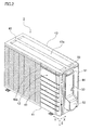
FIG. 2 is a perspective view showing an overall structure of an outdoor unit of the air conditioner shown inFIG. 1 . - [
FIG. 3 ]
FIG. 3 is a front view of a right side panel of the outdoor unit of the air conditioner shown inFIG. 1 . - [
FIG. 4 ]
FIG. 4 is an enlarged perspective view of the outdoor unit of the air conditioner shown inFIG. 1 , mainly showing the right side panel. - [
FIG. 5 ]
Fig. 5 is a sectional view taken along a line M-M ofFIG. 4 . - [
FIG. 6 ]
FIG. 6 is a sectional view taken along a line N-N ofFIG. 4 . - [
FIG. 7 ]
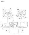
FIG. 7 is an enlarged schematic sectional view showing trap structures created by a top panel, the right side panel, and a shutoff valve cover of the outdoor unit of the air conditioner shown inFIG. 1 . - [
FIG. 8 ]
FIG. 8 is a front view showing the shutoff valve cover of the outdoor unit of the air conditioner shown inFIG. 1 . - [
FIG. 9 ]
FIG. 9 is a sectional view taken along a line J-J ofFIG. 8 . - [
FIG. 10 ]
FIG. 10 is an exploded perspective view of an electrical component box and a terminal block mounting plate of the outdoor unit of the air conditioner shown inFIG. 1 . - [
FIG. 11 ]
FIG. 11 is an enlarged perspective view of tab portions provided to the electrical component box shown inFIG. 10 with their peripheries. - [
FIG. 12 ]
FIG. 12 is a diagram schematically showing how to deflect a tab portion of the electrical component box shown inFIG. 10 . - [
FIG. 13 ]
FIG. 13 is a diagram schematically showing how to fix wires by the tab portion of the electrical component box shown inFIG. 10 . - [
FIG. 14 ]
FIG. 14 is a diagram schematically showing how to deflect a tab portion of an electrical component box of a modification. Description of Embodiments - The following describes an embodiment of an air conditioner having an outdoor unit in accordance with the present invention, with reference to the drawings.
- As shown in
FIG. 1 , anair conditioner 1 of this embodiment includes: anindoor unit 2 installed on an indoor wall surface or the like; anoutdoor unit 3 installed outside a room; andconnection pipes 4 which connect theindoor unit 2 to theoutdoor unit 3. Further, devices and valves contained in theindoor unit 2 and theoutdoor unit 3 are connected to theconnection pipes 4, and thereby a refrigerant circuit is constructed. The refrigerant circuit is mainly constituted by: anindoor heat exchanger 20; anoutdoor heat exchanger 30; acompressor 31; and anelectric expansion valve 32. At the time of cooling operation, a high-temperature and high-pressure refrigerant discharged from thecompressor 31 flows into theoutdoor heat exchanger 30. Subsequently, the refrigerant condensed in the outdoor heat exchanger (condenser) 30 is decompressed by theelectric expansion valve 32, and then flows into theindoor heat exchanger 20. Subsequently, the refrigerant evaporated in the indoor heat exchanger (evaporator) 20 returns to a sucking side of thecompressor 31. Air around theindoor heat exchanger 20 is thus cooled, so that cool air is provided to the room. Meanwhile, at the time of heating operation, a high-temperature and high-pressure refrigerant discharged from thecompressor 31 flows into theindoor heat exchanger 20. Subsequently, the refrigerant condensed in the indoor heat exchanger (condenser) 20 is decompressed by theelectric expansion valve 32, and then flows into theoutdoor heat exchanger 30. Subsequently, the refrigerant evaporated in the outdoor heat exchanger (evaporator) 30 returns to the sucking side of thecompressor 31. Air around theindoor heat exchanger 20 is thus heated, so that warm air is provided to the room. Note that, the "outdoor unit" of the present invention is applied to the air conditioner in this embodiment; however, the "outdoor unit" of the present invention is also applicable to a water heater. In this case, the water heater includes: the outdoor unit serving as a heat pump unit; and a tank unit. - The
indoor unit 2 includes: the above-describedindoor heat exchanger 20; and an indoor fan (cross-flow fan) 21 attached along theindoor heat exchanger 20. - The
outdoor unit 3 includes: the above-describedoutdoor heat exchanger 30; thecompressor 31 which compresses a refrigerant sucked therein; theelectric expansion valve 32 connected to theoutdoor heat exchanger 30; an outdoor fan (propeller fan) 33 attached with theoutdoor heat exchanger 30; anaccumulator 34 connected to the sucking side of thecompressor 31; and a four-pass switching valve 35 connected to a discharging side of thecompressor 31. Further, theoutdoor unit 3 is provided with afluid shutoff valve 36 and agas shutoff valve 37 to which theconnection pipes 4 are connected. - As shown in
FIG. 2 , the above-described devices (thecompressor 31,electric expansion valve 32,outdoor fan 33,accumulator 34, and four-pass switching valve 35) are contained in acasing 40 having a substantially box shape. Thecasing 40 includes: abottom panel 41 on which thecompressor 31 and the like are placed; aside panel 42 provided in a standing manner at an edge portion of thebottom panel 41; and atop panel 43 disposed so as to be opposed to thebottom panel 41. Theside panel 42 includes: aright side panel 44 forming a right side surface of thecasing 40; a left side panel (not-shown) forming a left side surface of thecasing 40; and afront panel 45 forming a front surface of thecasing 40. Thetop panel 43 has: a rectangulartop plate portion 43a forming a top surface of thecasing 40; and anedge portion 43b perpendicularly connected to end portions of thetop plate portion 43a. - As shown in
FIGs. 3 and6 , theright side panel 44 has: amain body 44a which has a substantially L-shape in horizontal section and is disposed as the right side surface of thecasing 40; and arear plate portion 44b which has a curved portion near a lateral end portion of themain body 44a and is disposed as a rear surface of thecasing 40. As shown inFIG. 3 , theright side panel 44 is provided with, above its vertically middle portion (i.e., its middle portion with respect to Z direction), awiring opening 46a through which wires (not-shown) connected to aterminal block 60 disposed in thecasing 40 are drawn from the inside of thecasing 40 to the outside. Thewiring opening 46a opens in the vicinity of theterminal block 60. Specifically, theterminal block 60 is disposed at a position where theterminal block 60 is exposed through thewiring opening 46a, that is, theterminal block 60 is provided within an area corresponding to thewiring opening 46a, with respect to a direction of a height of the right side panel 44 (the Z direction) and a direction of a width of the right side panel 44 (X direction) . Further, theright side panel 44 is provided with, below its vertically middle portion (i.e., the middle portion with respect to the Z direction), a shutoff valve opening 46b through which the above-describedfluid shutoff valve 36 andgas shutoff valve 37 are exposed. - Furthermore, in this embodiment, as shown in
FIGs. 5 and7 , anupper portion 47 above thewiring opening 46a is positioned inside an engagement portion K, where anupper end portion 53 of ashutoff valve cover 50 is engaged with theedge portion 43b of thetop panel 43. That is, theupper portion 47 is positioned inside aninner wall portion 53b which will be described later. Note that, theupper portion 47 extends to a position above theinner wall portion 53b. - As shown in
FIG. 3 , agroove 48 is formed on an outer surface of theright side panel 44, thegroove 48 being formed in at least a part of a region which is around thewiring opening 46a. Thegroove 48 includes: ahorizontal groove 48H formed along an upper edge of thewiring opening 46a; andvertical grooves wiring opening 46a, respectively. Thehorizontal groove 48H is connected to thevertical grooves horizontal groove 48H is designed so as to be longer than a width W2 of thewiring opening 46a, and with respect to the direction of the height of the right side panel 44 (the Z direction), a width W3 of each of thevertical grooves wiring opening 46a. Here, in this embodiment, theright side panel 44 is provided with, above thehorizontal groove 48H, avisor portion 49 protruding outward, as shown inFigs. 5 and7 . Thevisor portion 49 is positioned above the later-describedinner wall portion 53b of theshutoff valve cover 50, and functions to prevent water which has passed through a gap between theedge portion 43b of thetop panel 43 and theupper end portion 53 of the shutoff valve cover 50 from passing over theright side panel 44 and entering the inside. In this embodiment, a space is reserved between thetop plate portion 43a of thetop panel 43 and theinner wall portion 53b, and thevisor portion 49 is arranged in this space. - As shown in
FIG. 4 , the shutoff valve cover (opening cover) 50 made of resin is attached to an outer side of theright side panel 44. Theshutoff valve cover 50 is provided to cover: thewiring opening 46a (seeFIG. 3 ) formed in theright side panel 44; wires (not-shown) drawn out through thewiring opening 46a; and thefluid shutoff valve 36 and thegas shutoff valve 37 which are exposed through theshutoff valve opening 46b (seeFIG. 3 ) of theright side panel 44. As shown inFIGS. 4 ,8 , and9 , theshutoff valve cover 50 is provided with: agrip 51 gripped by an operator at the time of transportation of the outdoor unit; and a swellingportion 52 which swells outward and covers thefluid shutoff valve 36 and thegas shutoff valve 37. Theshutoff valve cover 50 of this embodiment is configured so that itsupper end portion 53 is engaged with theedge portion 43b of the top panel 43 (seeFIGs. 5 and7 ). As shown inFIGs. 5 ,7 , and9 , theupper end portion 53 of theshutoff valve cover 50 includes: anouter wall portion 53a positioned outside theedge portion 43b of thetop panel 43; theinner wall portion 53b positioned inside theedge portion 43b of thetop panel 43; and arecess 53c provided between theouter wall portion 53a and theinner wall portion 53b. Further, theedge portion 43b of thetop panel 43 is inserted into therecess 53c of theupper end portion 53, and thereby engagement is made by theedge portion 43b of thetop panel 43 and theupper end portion 53 of theshutoff valve cover 50. Each of the above-describedouter wall portion 53a,inner wall portion 53b, andrecess 53c extends along the direction of a width of the shutoff valve cover 50 (the X direction). - Further, as shown in
FIG. 6 ,lateral end portions shutoff valve cover 50 protrude toward theright side panel 44, and are positioned in the abode-mentionedvertical grooves right side panel 44, respectively. Thelateral end portion recesses lateral end portion vertical grooves right side panel 44 in a vertical direction (the Z direction). Thelateral end portion vertical grooves edge portion 43b of thetop panel 43 is inserted into therecess 53c formed at theupper end portion 53 of theshutoff valve cover 50. Furthermore,notches lateral end portions corners vertical grooves - As shown in
FIGs. 5 ,7 , and9 , (i) aportion 53d of a tip portion of theouter wall portion 53a, whichportion 53d is opposed to theinner wall portion 53b, and (ii) aportion 53e of a tip portion of theinner wall portion 53b, whichportion 53e is opposed to theouter wall portion 53a are tapered, and this facilitates the insertion of theedge portion 43b of thetop panel 43 into therecess 53c. Further, in this embodiment, a height H2 of theinner wall portion 53b is shorter than a height H1 of theouter wall portion 53a (seeFIG. 9 ). - The following describes, in detail, trap structures which prevent electrical components such as the
terminal block 60 from getting wet with water. - As shown in
FIG. 7 , a trap structure P which prevents entry of water from around theupper end portion 53 of theshutoff valve cover 50 is formed between theupper end portion 53 of theshutoff valve cover 50 and theedge portion 43b oftop panel 43. The trap structure P is constructed by inserting theedge portion 43b of thetop panel 43 into therecess 53c formed at theupper end portion 53 of theshutoff valve cover 50. The trap structure P includes: a vertical gap A formed between theouter wall portion 53a and theedge portion 43b of thetop panel 43; a horizontal gap B formed between a bottom surface of therecess 53c and a lower end surface of theedge portion 43b of thetop panel 43; and a vertical gap C formed between theinner wall portion 53b and theedge portion 43b of thetop panel 43. The vertical gap A, the horizontal gap B, and the vertical gap C collectively form a meandering gap having a substantially U-shape. Although sizes of the gaps A, B, and C depicted inFIG. 7 are exaggerated, in practice, theedge portion 43b of thetop panel 43 is substantially in contact with theupper end portion 53 of theshutoff valve cover 50. - As shown in
FIG. 7 , a trap structure Q which prevents entry of water having passed through the gap of the above-described trap structure P is formed between theinner wall portion 53b of theupper end portion 53 of theshutoff valve cover 50 and theright side panel 44. The trap structure Q is constructed by positioning theinner wall portion 53b into thehorizontal groove 48H of theright side panel 44. The trap structure Q includes: a horizontal gap D formed between an upper end surface of theinner wall portion 53b and thevisor portion 49 of theright side panel 44; and a vertical gap E formed between thehorizontal groove 48H and theinner wall portion 53b. The horizontal gap D and the vertical gap E collectively form a substantially L-shaped gap. Although sizes of the gaps D and E depicted inFIG. 7 are exaggerated, in practice, theright side panel 44 is substantially in contact with theinner wall portion 53b of theshutoff valve cover 50. - The above-described vertical gap A, horizontal gap B, vertical gap C, horizontal gap D, and vertical gap E collectively form a meandering gap having a substantially S-shape.
- As shown in
FIG. 7 , a trap structure R which prevents entry of water having passed through the gap of the trap structure P is formed between thetop panel 43 and thevisor portion 49 of theright side panel 44. The trap structure R is constructed by: positioning thevisor portion 49 above theinner wall portion 53b; and positioning thevisor portion 49 along an inner wall surface of thetop panel 43. The trap structure R includes: a vertical gap F formed between theedge portion 43b of thetop panel 43 and a protruded end surface of thevisor portion 49; and a horizontal gap G formed between thetop plate portion 43a of thetop panel 43 and an upper end surface of thevisor portion 49. These vertical gap F and horizontal gap G collectively form a substantially L-shaped gap. Although sizes of the gaps F and G depicted inFIG. 7 are exaggerated, in practice, there is formed a very small gap between theedge portion 43b of thetop panel 43 and thevisor portion 49. Note that theedge portion 43b of thetop panel 43 may be in contact with thevisor portion 49. In this case, the gaps F and G between theedge portion 43b of thetop panel 43 and thevisor portion 49 are not formed substantially, and this ensures that wetting of the electrical components such as theterminal block 60 with water entering through the gap between thevisor portion 49 of theright side panel 44 and theedge portion 43b of thetop panel 43 is prevented. - While the above-described trap structures P, Q, and R are provided for preventing the entry of water from around the
upper end portion 53 of theshutoff valve cover 50, a trap structure S is provided for preventing entry of water from around thelateral end portions shutoff valve cover 50 as shown inFIG. 6 . As shown inFIG. 6 , the trap structure S is constructed by positioning thelateral end portions shutoff valve cover 50 into thevertical grooves right side panel 44, respectively. - The following describes, in detail, an
electrical component box 70 disposed inside thecasing 40, with reference toFIGS. 10 to 13 . In theelectrical component box 70, acontrol board 62 on which various electronic components are mounted is attached. Thecontrol board 62 controls operation of devices such as thecompressor 31, theelectric expansion valve 32, theoutdoor fan 33, and the like. - The
electrical component box 70 is made of resin, and is one-piece molded. As shown inFIG. 10 , aboard receiver 70a which receives thecontrol board 62 is provided in theelectrical component box 70. Theboard receiver 70a is a space defined by atop portion 71, abottom portion 72, aright side portion 73, and aleft side portion 74, and thecontrol board 62 is disposed in theelectrical component box 70 in a standing manner. Theboard receiver 70a is provided with, at respective positions, a plurality ofsupport ribs 75 which hold thecontrol board 62 in a predetermined position with respect to a direction of a depth of theboard receiver 70a (the X direction). Further, theboard receiver 70a is provided with aclaw 76 to be engaged in a notch (not-shown) in thecontrol board 62. Theclaw 76 is flexible, and theclaw 76 is engaged in the notch (not-shown), so that thecontrol board 62 is fixed. Molding holes 78 used for removing a mold are bored through to correspond to the above-describedclaw 76 and protrusions 77 (seeFIG. 10 ) provided at plural positions in theboard receiver 70a. - Further, a mounting
plate installation place 70b where the terminalblock mounting plate 61 is to be installed is arranged at an outer surface of theright side portion 73 of theelectrical component box 70 of this embodiment. As shown inFIG. 11 , the mountingplate installation place 70b is provided withtab portions tab portions right side portion 73 using a pattern. Thetab portion 80A is structured so that its one end in the X direction is fixed and its other end in the X direction is free for deflection, while thetab portion 80B is structured so that its one end in the X direction is free for deflection and its other end in the X direction is fixed. With this structure, a direction in which wires 65 (seeFIG. 12 ) held by thetab portion 80A are released is opposite to a direction in which thewires 65 held by thetab portion 80B are released, and therefore it is possible to prevent thewires 65 held by thetab portions wires 65. - Further, in this embodiment, as shown in
FIG. 11 , aprotrusion 81A is formed on an outer surface (a surface facing the terminal block mounting plate 61) of thetab portion 80A, and aprotrusion 81B is formed on an outer surface (a surface facing the terminal block mounting plate 61) of thetab portion 80B. Theprotrusions FIG. 12 , theprotrusion 81A of thetab portion 80A is pressed by the terminalblock mounting plate 61 which is to be installed in the mountingplate installation place 70b, and thereby thetab portion 80A is deflected toward the inside of theelectrical component box 70. Thetab portion 80A is thus deflected toward the inside of theelectrical component box 70, and this allows thetab portion 80A to hold thewires 65 arranged in theelectrical component box 70 by clipping thewires 65. Note thatFIG. 12 only illustrates thetab portion 80A; however, the same is applied to thetab portion 80B, and therefore the description thereof is omitted. The above-described configuration enables thewires 65 in theelectrical component box 70 to be fixed by thetab portions FIG. 12 , thewires 65 are fixed at a position before theprotrusion 81A, however, thewires 65 may be fixed at a position beyond theprotrusion 81A as shown inFIG. 13 . In this case, theprotrusion 81A functions as means for preventing release of thewires 65, and therefore thewires 65 are fixed more firmly. - The outdoor unit of this embodiment has following characteristics.
- In the
outdoor unit 3 of this embodiment, at a position above thewiring opening 46a, engagement is made by theedge portion 43b of thetop panel 43 and theupper end portion 53 of theshutoff valve cover 50, and therefore the distance between the engagement portion K and thewiring opening 46a is long enough as compared to a case where such a portion for attaching theshutoff valve cover 50 is provided near thewiring opening 46a. This increases a length of a path of entering water from the outside of thecasing 40 to the electrical components such as theterminal block 60 inside thecasing 40, and therefore an intensity of water which passes through the engagement portion K is reduced, which prevents the electrical components such as theterminal block 60 from getting wet with water. - In the
outdoor unit 3 of this embodiment, theedge portion 43b of thetop panel 43 is inserted into therecess 53c provided between theouter wall portion 53a and theinner wall portion 53b, and thereby the meandering gap (the vertical gap A, the horizontal gap B, and the vertical gap C) is formed between theedge portion 43b of thetop panel 43 and theupper end portion 53 of theshutoff valve cover 50. The thus-formed trap structure P effectively prevents the electrical components such as theterminal block 60 from getting wet with water. - In the
outdoor unit 3 of this embodiment, theupper portion 47 of the right side panel 44 (the portion of theright side panel 44 which is above thewiring opening 46a) is positioned inside theinner wall portion 53b, and therefore theupper portion 47 functions as a barrier against water, which protects the electrical components such as theterminal block 60 from the water. This further prevents the electrical components such as theterminal block 60 from getting wet with water. - In the
outdoor unit 3 of this embodiment, thevisor portion 49 is provided to theright side panel 44, and therefore even if water having entered from the outside of thecasing 40 passes through the engagement portion K (the trap structure P) made by theedge portion 43b of thetop panel 43 and theupper end portion 53 of theshutoff valve cover 50, thevisor portion 49 positioned above theinner wall portion 53b prevents the water from passing over theright side panel 44 and entering into the inside of theright side panel 44.
In theoutdoor unit 3 of this embodiment, the protruded end surface of thevisor portion 49 is close to or in contact with theedge portion 43b of thetop panel 43, the upper end surface of thevisor portion 49 is close to or in contact with thetop plate portion 43a of thetop panel 43, and a lower end surface of thevisor portion 49 is close to or in contact with the upper end surface of theinner wall portion 53b. In this structure, the gap F between thevisor portion 49 and theedge portion 43b, the gap G between thevisor portion 49 and thetop plate portion 43a, and the gap D between thevisor portion 49 and the upper end surface of theinner wall portion 53b are not formed substantially, and this ensures that wetting of the electrical components with water entering through the gaps between thevisor portion 49 and thetop panel 43 and between thevisor portion 49 and theinner wall portion 53b is prevented. - In the
outdoor unit 3 of this embodiment, theupper portion 47 of the right side panel 44 (the portion of theright side panel 44 which is above thewiring opening 46a) is close to or in contact with theinner wall portion 53b, so that substantially no gap is formed between theinner wall portion 53b and theright side panel 44, and this ensures that wetting of the electrical components such as theterminal block 60 with water entering through the gap between theinner wall portion 53b of theshutoff valve cover 50 and theupper portion 47 of theright side panel 44 is prevented. - In the
outdoor unit 3 of this embodiment, therecess 53c is formed along the direction of the width of the shutoff valve cover 50 (the X direction), and thereby the upper edge of thewiring opening 46a is covered across its whole length, with the result that entry of water from above to thewiring opening 46a is blocked. - In the
outdoor unit 3 of this embodiment, thegroove 48 is formed on the outer surface of theright side panel 44, thegroove 48 being formed in at least a part of the region around thewiring opening 46a. Therefore, water having entered from the outside of thecasing 40 is guided by thegroove 48 to a predetermined place where the water should be discharged, before reaching thewiring opening 46a positioned in the vicinity of the electrical components such as theterminal block 60. - In the
outdoor unit 3 of this embodiment, thelateral end portions shutoff valve cover 50 are respectively inserted into thevertical grooves right side panel 44, and thereby meandering gaps are respectively formed between thevertical grooves right side panel 44 and the correspondinglateral end portions shutoff valve cover 50. The thus-structured trap structure S serves to effectively prevent the electrical components such as theterminal block 60 from getting wet with water, at portions lateral to thewiring opening 46a.
Further, thevertical grooves wiring opening 46a are covered across their whole lengths, with the result that entry of water in a lateral direction to thewiring opening 46a is further blocked. - In the
outdoor unit 3 of this embodiment, thevertical grooves wiring opening 46a, and this structure serves to effectively prevent the electrical components such as theterminal block 60 from getting wet with water, at the both portions lateral to thewiring opening 46a. - In the
outdoor unit 3 of this embodiment, theupper end portion 53 of theshutoff valve cover 50 is inserted into thehorizontal groove 48H of theright side panel 44, and thereby the meandering gap (the horizontal gap D and the vertical gap E) is formed between thehorizontal groove 48H of theright side panel 44 and theupper end portion 53 of theshutoff valve cover 50. The thus-structured trap structure Q serves to effectively prevent the electrical components such as theterminal block 60 from getting wet with water, at a portion above thewiring opening 46a.
Furthermore, thehorizontal groove 48H is formed along the direction of the width of the right side panel 44 (the X direction), and thereby the upper edge of thewiring opening 46a is covered across its whole length, with the result that entry of water from above to thewiring opening 46a is further blocked. - Moreover, the
outdoor unit 3 of this embodiment employs a structure such that thetab portions electrical component box 70. This structure brings about the following advantages. (1) This structure is realized without increasing the number of components because currently-used components such as the terminalblock mounting plate 61 or theterminal block 60 can be utilized as a member imparting a pressure from the outside. (2) If a protrusion protruding toward the inside of theelectrical component box 70, such as theprotrusions 77, is provided, amolding hole 78 used for removing the mold and a seal member to fill thehole 78 are needed. However, since theprotrusions tab portions - The embodiment of the present invention has been described hereinabove with reference to the drawings. The present invention however should not be limited to the above embodiment. The scope of the present invention is defined not only by the above description of the embodiment, but also by the claims, and shall encompass various modifications within the scope defined in claims and those which are equivalent to the claims.
- For example, in the above-described embodiment, the
protrusions tab portions electrical component box 70, and thetab portions electrical component box 70 as a result that theprotrusions block mounting plate 61. However, the present invention is not limited thereto, and may be structured so as to include anelectrical component box 170 and a terminalblock mounting plate 161 which are of a modification shown inFIG. 14 . Specifically, theelectrical component box 170 of the modification is provided with atab portion 180 which does not include a protrusion, and the terminalblock mounting plate 161 is provided with, at a portion thereof which faces thetab portion 180, aprotrusion 162 such as a screw. In this structure, thetab portion 180 is pressed by theprotrusion 162 provided on the terminalblock mounting plate 161, and is deflected toward the inside of theelectrical component box 70. This allows thewires 65 in theelectrical component box 70 to be fixed by thetab portion 180. That is, theprotrusions tab portions tab portions block mounting plate 61, alternatively. Further, when the above-mentioned screw serving as theprotrusion 162 is provided for fixing another member, an edge of a head portion of the screw is covered with thecorresponding tab portion - The present invention realizes an outdoor unit which is configured to restrain entry of water from the outside of its casing to electrical components inside the casing.
-
- 1
- air conditioner
- 3
- outdoor unit
- 40
- casing
- 41
- bottom panel
- 43
- top panel
- 43a
- top plate portion
- 43b
- edge portion
- 44
- right side panel
- 46a
- wiring opening (opening)
- 47
- upper portion
- 48
- groove
- 48H
- horizontal groove (upper groove)
- 48L, 48R
- vertical groove (side groove)
- 49
- visor portion
- 50
- shutoff valve cover (opening cover)
- 53
- upper end portion
- 54L, 54R
- lateral end portion
- 60
- terminal block (electrical component)
- 53a
- outer wall portion
- 53b
- inner wall portion
- 53c
- recess
Claims (13)
- An outdoor unit comprising:a casing including a bottom panel, a side panel, and a top panel;an electrical component contained in the casing;an opening which is formed at the side panel, and opens in a vicinity of the electrical component; andan opening cover which is positioned outside the side panel and covers the opening,wherein the top panel includesa top plate portion positioned so as to be opposed to the bottom panel, andan edge portion extending downward from an end portion of the top plate portion;wherein, at an upper end portion of the opening cover, there are formedan outer wall portion positioned outside the edge portion of the top panel,an inner wall portion positioned inside the edge portion of the top panel, anda recess provided between the outer wall portion and the inner wall portion; andwherein, at a position above the opening, the edge portion of the top panel is inserted into the recess formed at the upper end portion of the opening cover, and a portion of the side panel which portion is above the opening is positioned inside the inner wall portion.
- The outdoor unit according to claim 1, wherein the portion of the side panel which portion is above the opening includes a visor portion positioned between the top plate portion of the top panel and an upper end of the inner wall portion.
- The outdoor unit according to claim 2, wherein a protruded end surface of the visor portion is close to or in contact with the edge portion of the top panel.
- The outdoor unit according to claim 2 or 3, wherein an upper end surface of the visor portion is close to or in contact with the top plate portion of the top panel.
- The outdoor unit according to any one of claims 2 to 4, wherein a lower end surface of the visor portion is close to or in contract with the upper end of the inner wall portion.
- The outdoor unit according to any one of claims 1 to 5, wherein the portion of the side panel which portion is above the opening is close to or in contact with the inner wall portion.
- The outdoor unit according to any one of claims 1 to 6, wherein the recess is formed along a direction of a width of the opening cover.
- The outdoor unit according to any one of claims 1 to 7, wherein a groove is formed on an outer surface of the side panel, the groove being formed in at least a part of a region which is around the opening.
- The outdoor unit according to claim 8, wherein the groove includes a side groove positioned lateral to the opening, into which side groove a lateral end portion of the opening cover is inserted.
- The outdoor unit according to claim 9, wherein the side groove is formed along a direction of a height of the side panel.
- The outdoor unit according to claim 9 or 10, wherein the side groove includes two side grooves which are provided on both sides of the opening, respectively.
- The outdoor unit according to any one of claims 8 to 11, wherein the groove includes an upper groove positioned above the opening, into which upper groove the upper end portion of the opening cover is inserted.
- The outdoor unit according to claim 12, wherein the upper groove is formed along a direction of a width of the side panel.
Applications Claiming Priority (2)
| Application Number | Priority Date | Filing Date | Title |
|---|---|---|---|
| JP2009165386A JP4807445B2 (en) | 2009-07-14 | 2009-07-14 | Outdoor unit |
| PCT/JP2010/057759 WO2011007609A1 (en) | 2009-07-14 | 2010-05-06 | Outdoor unit |
Publications (2)
| Publication Number | Publication Date |
|---|---|
| EP2455674A1 true EP2455674A1 (en) | 2012-05-23 |
| EP2455674A4 EP2455674A4 (en) | 2018-02-14 |
Family
ID=43449219
Family Applications (1)
| Application Number | Title | Priority Date | Filing Date |
|---|---|---|---|
| EP10799671.2A Withdrawn EP2455674A4 (en) | 2009-07-14 | 2010-05-06 | Outdoor unit |
Country Status (4)
| Country | Link |
|---|---|
| EP (1) | EP2455674A4 (en) |
| JP (1) | JP4807445B2 (en) |
| CN (1) | CN102472510B (en) |
| WO (1) | WO2011007609A1 (en) |
Cited By (4)
| Publication number | Priority date | Publication date | Assignee | Title |
|---|---|---|---|---|
| EP2835590A1 (en) * | 2013-08-07 | 2015-02-11 | Mitsubishi Electric Corporation | Outdoor unit of air-conditioning apparatus |
| EP3421894A1 (en) * | 2017-06-29 | 2019-01-02 | Beijing Xiaomi Mobile Software Co., Ltd. | Housing for an air-conditioning outdoor machine and air-conditioning outdoor machine |
| EP3550214A4 (en) * | 2016-12-05 | 2019-11-20 | Mitsubishi Electric Corporation | EXTERNAL UNIT OF AIR CONDITIONING DEVICE |
| EP4459200A4 (en) * | 2022-03-25 | 2025-03-12 | Mitsubishi Electric Corporation | Heat exchange unit, and refrigeration cycle device |
Families Citing this family (8)
| Publication number | Priority date | Publication date | Assignee | Title |
|---|---|---|---|---|
| JP5891374B2 (en) * | 2011-05-17 | 2016-03-23 | パナソニックIpマネジメント株式会社 | Air conditioner outdoor unit |
| JP5942093B2 (en) * | 2012-04-04 | 2016-06-29 | パナソニックIpマネジメント株式会社 | Air conditioner |
| JP6135071B2 (en) * | 2012-08-24 | 2017-05-31 | ダイキン工業株式会社 | Refrigeration equipment outdoor unit |
| CN105444296B (en) * | 2015-12-22 | 2017-01-18 | 珠海格力电器股份有限公司 | Side panel components and appliances |
| EP3557149B1 (en) * | 2016-12-16 | 2021-01-20 | Mitsubishi Electric Corporation | Outdoor unit for air conditioner |
| JP6593402B2 (en) * | 2017-08-09 | 2019-10-23 | ダイキン工業株式会社 | Refrigeration unit outdoor unit |
| WO2019207745A1 (en) * | 2018-04-26 | 2019-10-31 | 日立ジョンソンコントロールズ空調株式会社 | Air conditioner |
| CN115406010B (en) * | 2021-05-28 | 2025-04-18 | 宁波奥克斯电气有限公司 | Electrical appliance cover and air conditioner |
Family Cites Families (8)
| Publication number | Priority date | Publication date | Assignee | Title |
|---|---|---|---|---|
| JPH09126496A (en) * | 1995-10-27 | 1997-05-16 | Matsushita Electric Ind Co Ltd | Air conditioner electrical cover |
| JPH11118209A (en) * | 1997-10-20 | 1999-04-30 | Fujitsu General Ltd | Outdoor unit of air conditioner |
| JP2000193275A (en) * | 1998-12-24 | 2000-07-14 | Matsushita Electric Ind Co Ltd | Outdoor unit power supply cover device for separation type air conditioner |
| JP3598955B2 (en) * | 2000-08-23 | 2004-12-08 | ダイキン工業株式会社 | Outdoor unit of air conditioner |
| JP4270836B2 (en) * | 2002-09-30 | 2009-06-03 | 株式会社長府製作所 | Air conditioner operation setting device |
| JP4711790B2 (en) * | 2005-09-26 | 2011-06-29 | 三洋電機株式会社 | Air conditioner |
| JP3985836B2 (en) * | 2005-11-25 | 2007-10-03 | ダイキン工業株式会社 | Air conditioner outdoor unit |
| JP4435823B2 (en) * | 2007-11-09 | 2010-03-24 | シャープ株式会社 | Opening cover device and air conditioner equipped with the same |
-
2009
- 2009-07-14 JP JP2009165386A patent/JP4807445B2/en not_active Expired - Fee Related
-
2010
- 2010-05-06 CN CN201080031999.6A patent/CN102472510B/en not_active Expired - Fee Related
- 2010-05-06 WO PCT/JP2010/057759 patent/WO2011007609A1/en not_active Ceased
- 2010-05-06 EP EP10799671.2A patent/EP2455674A4/en not_active Withdrawn
Non-Patent Citations (1)
| Title |
|---|
| See references of WO2011007609A1 * |
Cited By (7)
| Publication number | Priority date | Publication date | Assignee | Title |
|---|---|---|---|---|
| EP2835590A1 (en) * | 2013-08-07 | 2015-02-11 | Mitsubishi Electric Corporation | Outdoor unit of air-conditioning apparatus |
| US9388993B2 (en) | 2013-08-07 | 2016-07-12 | Mitsubishi Electric Corporation | Outdoor unit of air-conditioning apparatus |
| EP3550214A4 (en) * | 2016-12-05 | 2019-11-20 | Mitsubishi Electric Corporation | EXTERNAL UNIT OF AIR CONDITIONING DEVICE |
| US10962239B2 (en) | 2016-12-05 | 2021-03-30 | Mitsubishi Electric Corporation | Outdoor unit of air-conditioning apparatus |
| EP3421894A1 (en) * | 2017-06-29 | 2019-01-02 | Beijing Xiaomi Mobile Software Co., Ltd. | Housing for an air-conditioning outdoor machine and air-conditioning outdoor machine |
| US10816228B2 (en) | 2017-06-29 | 2020-10-27 | Beijing Xiaomi Mobile Software Co., Ltd. | Air-conditioning outdoor machine |
| EP4459200A4 (en) * | 2022-03-25 | 2025-03-12 | Mitsubishi Electric Corporation | Heat exchange unit, and refrigeration cycle device |
Also Published As
| Publication number | Publication date |
|---|---|
| CN102472510B (en) | 2014-08-06 |
| JP2011021776A (en) | 2011-02-03 |
| WO2011007609A1 (en) | 2011-01-20 |
| EP2455674A4 (en) | 2018-02-14 |
| JP4807445B2 (en) | 2011-11-02 |
| CN102472510A (en) | 2012-05-23 |
Similar Documents
| Publication | Publication Date | Title |
|---|---|---|
| CN102472510B (en) | Outdoor unit | |
| EP3124888B1 (en) | Indoor unit of air conditioner | |
| CN101595349B (en) | Outdoor unit of air conditioner | |
| CN104976699B (en) | The outdoor unit of air conditioner | |
| EP2833079B1 (en) | Internal unit for air conditioner | |
| EP3239619B1 (en) | Outdoor machine | |
| CN109237640B (en) | Air conditioner outdoor unit and air conditioner | |
| EP3447393B1 (en) | Heat source unit | |
| KR20050018481A (en) | Outdoor unit of air conditioner | |
| US20070006610A1 (en) | Outdoor unit of an air conditioner | |
| US20110214443A1 (en) | Air conditioner | |
| EP3208548A1 (en) | Outdoor machine for air-conditioner | |
| KR100536874B1 (en) | Outdoor unit of air conditioner | |
| AU2006317274A1 (en) | Outdoor unit for air conditioner | |
| US12410922B2 (en) | Outdoor unit of air conditioner | |
| KR101735839B1 (en) | Waterproof structure for motor register | |
| KR101690885B1 (en) | Indoor unit for air conditoiner | |
| CN111480036A (en) | Outdoor unit of refrigeration cycle device | |
| KR20170019583A (en) | Indoor unit for air conditoiner | |
| US11435112B2 (en) | Outdoor unit of air-conditioning apparatus and method for manufacturing the same | |
| JP4396658B2 (en) | Electrical component box | |
| WO2014205795A1 (en) | Housing for vehicle hvac system | |
| JP7383115B2 (en) | Outdoor unit | |
| JP2003163478A (en) | Electronic unit storage box | |
| KR102533090B1 (en) | Indoor unit of air conditioner |
Legal Events
| Date | Code | Title | Description |
|---|---|---|---|
| PUAI | Public reference made under article 153(3) epc to a published international application that has entered the european phase |
Free format text: ORIGINAL CODE: 0009012 |
|
| 17P | Request for examination filed |
Effective date: 20120209 |
|
| AK | Designated contracting states |
Kind code of ref document: A1 Designated state(s): AL AT BE BG CH CY CZ DE DK EE ES FI FR GB GR HR HU IE IS IT LI LT LU LV MC MK MT NL NO PL PT RO SE SI SK SM TR |
|
| DAX | Request for extension of the european patent (deleted) | ||
| RA4 | Supplementary search report drawn up and despatched (corrected) |
Effective date: 20180115 |
|
| RIC1 | Information provided on ipc code assigned before grant |
Ipc: F24F 1/22 20110101ALI20180109BHEP Ipc: F24F 1/54 20110101AFI20180109BHEP Ipc: F24F 1/56 20110101ALI20180109BHEP |
|
| GRAP | Despatch of communication of intention to grant a patent |
Free format text: ORIGINAL CODE: EPIDOSNIGR1 |
|
| STAA | Information on the status of an ep patent application or granted ep patent |
Free format text: STATUS: GRANT OF PATENT IS INTENDED |
|
| RIC1 | Information provided on ipc code assigned before grant |
Ipc: F24F 1/22 20110101ALI20190613BHEP Ipc: F24F 1/56 20110101ALI20190613BHEP Ipc: F24F 1/54 20110101AFI20190613BHEP |
|
| INTG | Intention to grant announced |
Effective date: 20190712 |
|
| STAA | Information on the status of an ep patent application or granted ep patent |
Free format text: STATUS: THE APPLICATION IS DEEMED TO BE WITHDRAWN |
|
| 18D | Application deemed to be withdrawn |
Effective date: 20191123 |