EP2455609A2 - Blade for wind power generation and wind turbine - Google Patents
Blade for wind power generation and wind turbine Download PDFInfo
- Publication number
- EP2455609A2 EP2455609A2 EP11158370A EP11158370A EP2455609A2 EP 2455609 A2 EP2455609 A2 EP 2455609A2 EP 11158370 A EP11158370 A EP 11158370A EP 11158370 A EP11158370 A EP 11158370A EP 2455609 A2 EP2455609 A2 EP 2455609A2
- Authority
- EP
- European Patent Office
- Prior art keywords
- outer skin
- blade
- side outer
- power generation
- main body
- Prior art date
- Legal status (The legal status is an assumption and is not a legal conclusion. Google has not performed a legal analysis and makes no representation as to the accuracy of the status listed.)
- Withdrawn
Links
- 238000010248 power generation Methods 0.000 title claims abstract description 38
- 229920000049 Carbon (fiber) Polymers 0.000 claims abstract description 37
- 239000004917 carbon fiber Substances 0.000 claims abstract description 37
- VNWKTOKETHGBQD-UHFFFAOYSA-N methane Chemical compound C VNWKTOKETHGBQD-UHFFFAOYSA-N 0.000 claims abstract description 36
- 239000002131 composite material Substances 0.000 claims abstract description 22
- 229920005989 resin Polymers 0.000 claims description 13
- 239000011347 resin Substances 0.000 claims description 13
- 239000003365 glass fiber Substances 0.000 claims description 8
- 238000011144 upstream manufacturing Methods 0.000 abstract description 5
- 238000006073 displacement reaction Methods 0.000 description 19
- 229920002239 polyacrylonitrile Polymers 0.000 description 14
- 239000000463 material Substances 0.000 description 9
- 230000000052 comparative effect Effects 0.000 description 7
- 238000004088 simulation Methods 0.000 description 7
- 239000011248 coating agent Substances 0.000 description 4
- 239000000835 fiber Substances 0.000 description 4
- ZEASXVYVFFXULL-UHFFFAOYSA-N amezinium metilsulfate Chemical compound COS([O-])(=O)=O.COC1=CC(N)=CN=[N+]1C1=CC=CC=C1 ZEASXVYVFFXULL-UHFFFAOYSA-N 0.000 description 2
- 238000010586 diagram Methods 0.000 description 2
- 229920003023 plastic Polymers 0.000 description 2
- 239000004033 plastic Substances 0.000 description 2
- 239000002243 precursor Substances 0.000 description 2
- OOJYPCDXFPWXFL-UHFFFAOYSA-N [C].OC1=CC=CC=C1 Chemical compound [C].OC1=CC=CC=C1 OOJYPCDXFPWXFL-UHFFFAOYSA-N 0.000 description 1
- 238000010000 carbonizing Methods 0.000 description 1
- 239000011280 coal tar Substances 0.000 description 1
- 238000000576 coating method Methods 0.000 description 1
- 230000007423 decrease Effects 0.000 description 1
- 230000003247 decreasing effect Effects 0.000 description 1
- 239000000295 fuel oil Substances 0.000 description 1
- 239000003208 petroleum Substances 0.000 description 1
- 239000002994 raw material Substances 0.000 description 1
- 239000012779 reinforcing material Substances 0.000 description 1
Images


Classifications
-
- F—MECHANICAL ENGINEERING; LIGHTING; HEATING; WEAPONS; BLASTING
- F03—MACHINES OR ENGINES FOR LIQUIDS; WIND, SPRING, OR WEIGHT MOTORS; PRODUCING MECHANICAL POWER OR A REACTIVE PROPULSIVE THRUST, NOT OTHERWISE PROVIDED FOR
- F03D—WIND MOTORS
- F03D1/00—Wind motors with rotation axis substantially parallel to the air flow entering the rotor
- F03D1/06—Rotors
- F03D1/065—Rotors characterised by their construction elements
- F03D1/0675—Rotors characterised by their construction elements of the blades
-
- Y—GENERAL TAGGING OF NEW TECHNOLOGICAL DEVELOPMENTS; GENERAL TAGGING OF CROSS-SECTIONAL TECHNOLOGIES SPANNING OVER SEVERAL SECTIONS OF THE IPC; TECHNICAL SUBJECTS COVERED BY FORMER USPC CROSS-REFERENCE ART COLLECTIONS [XRACs] AND DIGESTS
- Y02—TECHNOLOGIES OR APPLICATIONS FOR MITIGATION OR ADAPTATION AGAINST CLIMATE CHANGE
- Y02E—REDUCTION OF GREENHOUSE GAS [GHG] EMISSIONS, RELATED TO ENERGY GENERATION, TRANSMISSION OR DISTRIBUTION
- Y02E10/00—Energy generation through renewable energy sources
- Y02E10/70—Wind energy
- Y02E10/72—Wind turbines with rotation axis in wind direction
Definitions
- the present invention relates to a blade for wind power generation that is used in wind power generation, and a wind turbine that uses the blade for wind power generation.
- blades for wind power generation are being increased to achieve high output from wind turbines.
- damage or deformation of the blade that accompanies wind resistance or rotation is prevented by providing a reinforcing material inside the blade (for example, see Japanese Patent Laid-Open No. 2002-357176 ).
- NREL National Renewable Energy Laboratory
- An object of the present invention is to provide a blade for wind power generation that makes it possible to increase the size of a blade for wind power generation by suppressing deformations of a blade for wind power generation, as well as a wind turbine that uses the blade for wind power generation.
- a blade for wind power generation is attachable to a rotor hub, and includes a wing-shaped outer skin, a plurality of webs that are provided inside the outer skin and extend towards a tip of the blade, a pair of girders that are adhered to both edges of the webs and are adhered to the outer skin, a nose portion provided at a front end portion in a direction of rotation of the outer skin, and a tail portion provided at a rear end portion in the direction of rotation of the outer skin, wherein the girders, nose portion, and tail portion are formed with a pitch-based carbon fiber composite that is obtained by impregnating a resin into a pitch-based carbon fiber.
- a nose portion and a tail portion by forming girders, a nose portion and a tail portion with a pitch-based carbon fiber composite having a high modulus, even if a strong external force acts on the outer skin and the web, a joined state of the outer skin and the web can be maintained. It is thus possible to suppress deformation of the blade for wind power generation.
- a pitch-based carbon fiber for the girders by using a pitch-based carbon fiber for the girders, a deformation that occurs in the front-to-rear direction of the blade for wind power generation can be suppressed, and by using a pitch-based carbon fiber for the nose portion and tail portion, a deformation that occurs in the direction of rotation of the blade for wind power generation can be suppressed.
- the size of the blade for wind power generation can be increased.
- the outer skin and web are formed with a PAN-based carbon fiber composite that is obtained by impregnating a resin into a PAN-based carbon fiber.
- a PAN-based carbon fiber composite that is obtained by impregnating a resin into a PAN-based carbon fiber.
- the outer skin and web are preferably formed with a glass fiber composite that is obtained by impregnating a resin into a glass fiber.
- a wind turbine according to the present invention uses any of the above described blades for wind power generation. Since it is thereby possible to increase the size of the blade for wind power generation, the wind turbine can be designed to have a high output.
- the present invention it is possible to suppress deformation of a blade for wind power generation and increase the size of the blade for wind power generation.
- FIG. 1 is an outline configuration diagram that illustrates a wind turbine that uses a blade according to the embodiments
- a direction in which wind flows with respect to the blade for wind power generation is referred to as the "front-to-rear direction"
- an upstream side of wind at the blade for wind power generation is referred to as the "front side”
- a downstream side of wind at the blade for wind power generation is referred to as the "rear side”.
- a direction in which the blade for wind power generation rotates is referred to as the "direction of rotation”.
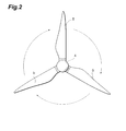
- FIG. 1 is an outline configuration diagram that illustrates a wind turbine that uses a blade according to the embodiments.
- FIG. 2 is a partial enlarged view that shows the wind turbine illustrated in FIG. 1 when viewed from an upstream side.
- a wind turbine 1 includes a tower 2 that is vertically installed on the ocean, a nacelle housing 3 that is connected to the top of the tower 2, a rotor hub 4 that is rotatably connected to a front end of the nacelle housing 3, and three blades 5 that are connected to the rotor hub 4.
- the nacelle housing 3 rotatably retains a main shaft 6 that is connected to a rotor shaft of the rotor hub 4.
- a generator 7 that converts rotational energy of the main shaft 6 into electrical energy is mounted in the nacelle housing 3. Consequently, when the blades 5 receive the wind and cause the rotor hub 4 to rotate, the main shaft 6 rotates and rotational energy of the main shaft 6 is converted to electrical energy by the generator 7 to generate electric power.
- the generated electric power is accumulated in a current collector apparatus 8 installed at the lower part of the tower 2, and then distributed to various places.
- FIG. 3 is a plane view of the blade.
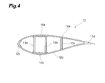
- FIG. 4 is a cross-sectional view along line IV-IV shown in FIG. 3 .
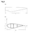
- FIG. 5 includes views for describing the dimensions of the blade, in which FIG. 5(a) is a plane view of the blade that corresponds to FIG. 3 , and FIG. 5(b) is a cross-sectional view of the blade that corresponds to FIG. 4 .
- the X-axis direction represents the direction of rotation and the Y-axis direction represents the front-to-rear direction.
- the blade 5 is a large-sized blade formed in a wing shape, and a blade length L thereof is 90 meters.
- the blade 5 includes a root 11 connected to the rotor hub 4, a blade main body 12 that receives wind and obtains a rotary force, three webs 13 that are provided inside the blade main body 12, and girders 14 that connect the web 13 and the blade main body 12.
- the root 11 has a concentric cylindrical structure, and has a material thickness that is greater than that of the blade main body 12 in order to secure the connection strength with the rotor hub 4.
- the blade main body 12 is formed in a wing shape that obtains a rotary force aerodynamically.
- the material thickness of the blade main body 12 is thinner than that of the root 11 in order to achieve a light weight.
- the root 11 (proximal end) side of the blade main body 12 changes from a cylindrical structure to a wing-shaped deformation ellipsoid structure, and a chord W thereof gradually widens.
- the tip side of the blade main body 12 is a wing-shaped deformation ellipsoid structure, and a chord W thereof gradually narrows.
- a thickness D of a front portion in the direction of rotation of the blade main body 12 gradually increases to reach a maximum thickness.
- a thickness D of a rear portion in the direction of rotation of the blade main body 12 gradually decreases, and the tail of the blade extends in a long manner in accompaniment therewith.
- the principal components of the blade main body 12 formed in this manner are a front side outer skin 12a and a rear side outer skin 12b that are divided between the upstream side and the downstream side and face each other, a nose portion 12c disposed at the front end portion in the direction of rotation of the front side outer skin 12a and the rear side outer skin 12b, and a tail portion 12d disposed at the rear end portion in the direction of rotation of the front side outer skin 12a and the rear side outer skin 12b.
- the nose portion 12c and the tail portion 12d are disposed between the front side outer skin 12a and the rear side outer skin 12b.
- the end surfaces of the front side outer skin 12a and the rear side outer skin 12b are adhered to the nose portion 12c and the tail portion 12d, so that the blade main body 12 forms a wing shape.
- the web 13 is formed in an elongated plate shape that extends towards the tip of the blade main body 12.
- the web 13 is disposed in an approximately perpendicular state with respect to the front side outer skin 12a and the rear side outer skin 12b.
- One edge thereof is directly or indirectly connected to the front side outer skin 12a, and the other edge is directly or indirectly connected to the rear side outer skin 12b.
- the web 13 functions to support the front side outer skin 12a and rear side outer skin 12b that are facing each other and suppress a deformation in the front-to-rear direction of the blade main body 12.
- Three of the webs 13 formed in this manner are arranged in parallel along the direction of rotation of the blade main body 12.
- two webs 13a and 13b that are disposed at the front side in the direction of rotation of the blade main body 12 are arranged at positions at which the distance between the front side outer skin 12a and the rear side outer skin 12b has become wide. These positions are in the vicinity of the center of the direction of rotation of the blade main body 12.
- a web 13c among the three webs 13 that is disposed on a rear side in the direction of rotation of the blade main body 12 is disposed at a position at which the distance between the front side outer skin 12a and the rear side outer skin 12b has become narrow. This position is towards the rear in the direction of rotation (position in the vicinity of the tail of the blade) of the blade main body 12.
- Both edges of the webs 13a and 13b are adhered to the front side outer skin 12a and the rear side outer skin 12b through the girders 14. Both edges of the web 13c are directly adhered to the front side outer skin 12a and the rear side outer skin 12b.
- a configuration may also be adopted in which the webs 13a to 13c are adhered to the girders 14 or the front side outer skin 12a and rear side outer skin 12b via an unshown bracket member.
- Two of the girders 14 form one set that includes a girder 14a that is adherently fixed to one edge of the web 13a and the web 13b and an inner wall of the front side outer skin 12a, and a girder 14b that is adherently fixed to the other edge of the web 13a and the web 13b and an inner wall of the rear side outer skin 12b.
- the girder 14a is formed in an elongated plate shape that extends from at least one edge of the web 13a to one edge of the web 13b.
- the girder 14b is formed in an elongated plate shape that extends from at least the other edge of the web 13a to the other edge of the web 13b. Consequently, by adhering the girders 14a and 14b to the two edges of the webs 13a and 13b, the webs 13a and 13b and the girders 14a and 14b form a closed section.
- the root 11 is formed with a PAN-based carbon fiber composite that is obtained by impregnating a resin into PAN (polyacrylonitrile)-based carbon fiber of continuous fiber.
- the front side outer skin 12a, the rear side outer skin 12b, and the web 13 of the blade main body 12 are formed with a PAN-based carbon fiber composite that is obtained by impregnating a resin into PAN-based carbon fiber.
- the PAN-based carbon fiber is obtained by carbonizing a PAN precursor (polyacrylonitrile fiber), and has a high-strength property with excellent shear strength.
- the nose portion 12c, the tail portion 12d, and the girders 14 of the blade main body 12 are formed with a pitch-based carbon fiber composite that is obtained by impregnating a resin into pitch-based carbon fiber of continuous fiber.
- Pitch-based carbon fiber is obtained by baking a pitch precursor (a pitch fiber obtained using coal tar or petroleum heavy oil as a raw material), and has a high modulus.
- the tensile modulus of the pitch-based carbon fiber forming the nose portion 12c, the tail portion 12d, and the girders 14 of the blade main body 12 is preferably 400 to 900 GPa from the viewpoint of suppressing deformation of the blade tip, and more preferably is 550 to 750 GPa.
- the thermal conductivity of the pitch-based carbon fiber is preferably 80 to 700 W/m ⁇ K from the viewpoint of diffusing thermal energy at the time of a lightning strike. Further, the volume resistivity of the pitch-based carbon fiber is preferably 1.5 to 7.5 ⁇ m from the viewpoint of diffusing electrical energy at the time of a lightning strike.
- the strength of the blade 5 can be improved.
- the girders 14, the nose portion 12c, and the tail portion 12d with a high modulus pitch-based carbon fiber composite even if a strong external force acts on the front side outer skin 12a, the rear side outer skin 12b, and the webs 13, the joined state of the front side outer skin 12a, the rear side outer skin 12b, and the webs 13 can be maintained. Consequently, deformation of the blade 5 can be suppressed.
- the rigidity of the webs 13 and girders 14 can be increased.
- deformations of the blade 5 can be further suppressed.
- the blade main body 12 is formed by disposing the nose portion 12c and the tail portion 12d between the front side outer skin 12a and the rear side outer skin 12b, for example, the blade main body may be formed as illustrated in FIG. 6 .
- the front side outer skin 22a and the rear side outer skin 22b are directly adhered, and a nose portion 22c and a tail portion 22d of a predetermined thickness are layered on the front side outer skin 22a and rear side outer skin 22b that are adhered.
- the nose portion 22c and the tail portion 22d may be layered on either the front surface side or the rear surface side of the front side outer skin 22a and the rear side outer skin 22b, or may be layered on both surface sides of the front side outer skin 22a and the rear side outer skin 22b.
- the blade main body 12 is formed with the front side outer skin 12a, the rear side outer skin 12b, the nose portion 12c, and the tail portion 12d
- the blade main body may be formed as illustrated in FIG. 7 .
- the front side outer skin 32 is divided into a first front side outer skin 32a that is at a front portion in the direction of rotation and a second front side outer skin 32b that is at a rear portion in the direction of rotation.
- the rear side outer skin 33 is divided into a first rear side outer skin 33a that is at a front portion in the direction of rotation and a second rear side outer skin 33b that is at a rear portion in the direction of rotation.
- a girder 34a is disposed between the first front side outer skin 32a and the second front side outer skin 32b.
- the girder 34a is adhered to an end surface of the first front side outer skin 32a and the second front side outer skin 32b.
- a girder 34b is disposed between the first rear side outer skin 33a and the second rear side outer skin 33b.
- the girder 34b is adhered to an end surface of the first rear side outer skin 33a and the second rear side outer skin 33b.
- the blade main body 31 is formed by the front side outer skin 32 that is divided into a first front side outer skin 32a and a second front side outer skin 32b, the rear side outer skin 33 that is divided into a first rear side outer skin 33a and a second rear side outer skin 33b, the nose portion 12c disposed at a front end portion in the direction of rotation of the front side outer skin 32 and the rear side outer skin 33, the tail portion 12d disposed at a rear end portion in the direction of rotation of the front side outer skin 32 and the rear side outer skin 33, the girder 34a disposed between the first front side outer skin 32a and the second front side outer skin 32b, and the girder 34b disposed between the first rear side outer skin 33a and the second rear side outer skin 33b.
- a coating agent may be coated on these surfaces.
- Various materials such as resin or a carbon fiber pre-preg (pre-impregnated) can be used as the coating agent.
- the root 11, the front side outer skin 12a, the rear side outer skin 12b, and the webs 13 are formed with a PAN-based carbon fiber composite
- these components may be formed with any kind of material as long as the material is a high-strength material with excellent shear strength.
- these components may be formed with a glass fiber composite that is obtained by impregnating a resin into a glass fiber.
- Example 1 a blade for wind power generation with a blade length of 90 m that has the same structure as the blade 5 according to the above described embodiment is used.
- a pre-preg obtained by impregnating a resin into phenol carbon fiber with an orientation angle of 45 degrees was used as a PAN-based carbon fiber composite for forming the root, front side outer skin, rear side outer skin, and three webs.
- a pre-preg obtained by impregnating a resin into DIALEAD (registered trademark of Mitsubishi Plastics Inc.) K63712 manufactured by Mitsubishi Plastics Inc. was used as a pitch-based carbon fiber composite for forming the nose portion, the tail portion, and the two girders.
- This DIALEAD product has a high modulus, and the tensile modulus thereof is approximately 640 GPa, the tensile strength is approximately 2600 MPa, the breaking elongation is approximately 0.4%, the density is approximately 2.12 g/cm 3 , the yield is approximately 2000 g/1000 m, the thermal conductivity is approximately 140 W/m ⁇ K, and the volume resistivity is approximately 6 to 7 ⁇ m. Further, the safety factor according to Example 1 was 2.
- FIG. 8 includes views that illustrate the simulation results of Example 1, in which FIG. 8(a) shows the displacement in the X-axis direction (direction of rotation) and FIG. 8(b) shows the displacement in the Y-axis direction (front-to-rear direction).
- Example 2 a blade for wind power generation with a blade length of 90 m that has the same structure and the same materials as in Example 1 was used.
- the safety factor according to Example 2 was 3.
- FIG. 9 includes views that show the simulation results of Example 2, in which FIG. 9(a) shows the displacement in the X-axis direction (direction of rotation) and FIG. 9(b) shows the displacement in the Y-axis direction (front-to-rear direction).
- Example 1 For Comparative Example 1, a blade for wind power generation with a blade length of 90 m and the same structure as in Example 1 was used. A glass fiber composite was used as the material of the entire blade for wind power generation.
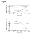
- FIG. 10 includes views that illustrate the simulation results of Comparative Example 1, in which FIG. 10(a) shows the displacement in the X-axis direction (direction of rotation) and FIG. 10(b) shows the displacement in the Y-axis direction (front-to-rear direction).
- front side outer skin 32a ... first front side outer skin, 32b ... second front side outer skin, 33 ... rear side outer skin, 33a ... first rear side outer skin, 33b ... second rear side outer skin, 34a ... girder, 34b ... girder, L ... blade length, W ... chord, D ... thickness
Abstract
Description
- The present invention relates to a blade for wind power generation that is used in wind power generation, and a wind turbine that uses the blade for wind power generation.
- Currently, the sizes of blades for wind power generation (hereunder, may be referred to as "blade") are being increased to achieve high output from wind turbines. When using a large-sized blade, damage or deformation of the blade that accompanies wind resistance or rotation is prevented by providing a reinforcing material inside the blade (for example, see Japanese Patent Laid-Open No.
2002-357176 - SUMMARY OF THE INVENTION
- Recently, the concept of an offshore wind turbine in which a wind turbine is installed on the ocean is been studied. According to this concept, the application of carbon fiber is being examined in order to increase the size of a blade for wind power generation used by the wind turbine.
- However, there is the problem that when a blade that has a blade length that exceeds the assumptions of the NREL is used, a deformation that occurs in the front-to-rear direction of the blade or a deformation that occurs in the direction of rotation of the blade becomes excessive, and hence it is not possible to meet the demands of this situation by merely using carbon fiber only.
- An object of the present invention is to provide a blade for wind power generation that makes it possible to increase the size of a blade for wind power generation by suppressing deformations of a blade for wind power generation, as well as a wind turbine that uses the blade for wind power generation.
- A blade for wind power generation according to the present invention is attachable to a rotor hub, and includes a wing-shaped outer skin, a plurality of webs that are provided inside the outer skin and extend towards a tip of the blade, a pair of girders that are adhered to both edges of the webs and are adhered to the outer skin, a nose portion provided at a front end portion in a direction of rotation of the outer skin, and a tail portion provided at a rear end portion in the direction of rotation of the outer skin, wherein the girders, nose portion, and tail portion are formed with a pitch-based carbon fiber composite that is obtained by impregnating a resin into a pitch-based carbon fiber.
- According to the present invention, by forming girders, a nose portion and a tail portion with a pitch-based carbon fiber composite having a high modulus, even if a strong external force acts on the outer skin and the web, a joined state of the outer skin and the web can be maintained. It is thus possible to suppress deformation of the blade for wind power generation. In particular, by using a pitch-based carbon fiber for the girders, a deformation that occurs in the front-to-rear direction of the blade for wind power generation can be suppressed, and by using a pitch-based carbon fiber for the nose portion and tail portion, a deformation that occurs in the direction of rotation of the blade for wind power generation can be suppressed. As the result of being able to suppress deformation of the blade for wind power generation in this manner, the size of the blade for wind power generation can be increased. Hence, it is possible to construct a wind turbine so as to have a high output.
- Preferably, the outer skin and web are formed with a PAN-based carbon fiber composite that is obtained by impregnating a resin into a PAN-based carbon fiber. By forming the outer skin and web with a high-strength PAN-based carbon fiber in this manner, the strength of the blade for wind power generation can be improved.
- Further, the outer skin and web are preferably formed with a glass fiber composite that is obtained by impregnating a resin into a glass fiber. By forming the outer skin and web with a high-strength glass fiber in this manner, the strength of the blade for wind power generation can be improved.
- A wind turbine according to the present invention uses any of the above described blades for wind power generation. Since it is thereby possible to increase the size of the blade for wind power generation, the wind turbine can be designed to have a high output.
- According to the present invention, it is possible to suppress deformation of a blade for wind power generation and increase the size of the blade for wind power generation.
-
FIG. 1 is an outline configuration diagram that illustrates a wind turbine that uses a blade according to the embodiments; -
FIG. 2 is a partial enlarged view that shows the wind turbine illustrated inFIG. 1 when viewed from an upstream side; -
FIG. 3 is a plane view of the blade; -
FIG. 4 is a cross-sectional view along line IV-IV shown inFIG. 3 ; -
FIG. 5 includes views for describing the dimensions of the blade, in which (a) is a plane view of the blade that corresponds toFIG. 3 , and (b) is a cross-sectional view of the blade that corresponds toFIG. 4 ; -
FIG. 6 is a cross-sectional view of the main body of another blade; -
FIG. 7 is a cross-sectional view of the main body of another blade; -
FIG. 8 includes views that show simulation results of Example 1, in which (a) shows displacements in the X-axis direction (direction of rotation), and (b) shows displacements in the Y-axis direction (front-to-rear direction); -
FIG. 9 includes views that show simulation results of Example 2, in which (a) shows displacements in the X-axis direction (direction of rotation), and (b) shows displacements in the Y-axis direction (front-to-rear direction); and -
FIG. 10 includes views that show simulation results of Comparative Example 1, in which (a) shows displacements in the X-axis direction (direction of rotation), and (b) shows displacements in the Y-axis direction (front-to-rear direction). - Hereunder, preferred embodiments of the blade for wind power generation and the wind turbine according to the present invention are described in detail referring to the drawings. The embodiments describe a case in which the present invention is applied to a large-sized blade that has a blade length of 90 meters. In the embodiments, a direction in which wind flows with respect to the blade for wind power generation is referred to as the "front-to-rear direction", an upstream side of wind at the blade for wind power generation is referred to as the "front side", and a downstream side of wind at the blade for wind power generation is referred to as the "rear side". Further, in the embodiments, a direction in which the blade for wind power generation rotates is referred to as the "direction of rotation". In this connection, portions that are the same or corresponding in the embodiments are denoted by the same reference numbers.
- First, an outline of a wind turbine that uses a blade according to the embodiments is described referring to
FIG. 1 andFIG. 2 .FIG. 1 is an outline configuration diagram that illustrates a wind turbine that uses a blade according to the embodiments.FIG. 2 is a partial enlarged view that shows the wind turbine illustrated inFIG. 1 when viewed from an upstream side. - As shown in
FIG. 1 andFIG. 2 , awind turbine 1 includes atower 2 that is vertically installed on the ocean, anacelle housing 3 that is connected to the top of thetower 2, arotor hub 4 that is rotatably connected to a front end of thenacelle housing 3, and threeblades 5 that are connected to therotor hub 4. - The
nacelle housing 3 rotatably retains amain shaft 6 that is connected to a rotor shaft of therotor hub 4. Agenerator 7 that converts rotational energy of themain shaft 6 into electrical energy is mounted in thenacelle housing 3. Consequently, when theblades 5 receive the wind and cause therotor hub 4 to rotate, themain shaft 6 rotates and rotational energy of themain shaft 6 is converted to electrical energy by thegenerator 7 to generate electric power. The generated electric power is accumulated in acurrent collector apparatus 8 installed at the lower part of thetower 2, and then distributed to various places. - Next, the structure of the
blade 5 is described in detail referring toFIG. 3 to FIG. 5 .FIG. 3 is a plane view of the blade.FIG. 4 is a cross-sectional view along line IV-IV shown inFIG. 3 .FIG. 5 includes views for describing the dimensions of the blade, in whichFIG. 5(a) is a plane view of the blade that corresponds toFIG. 3 , andFIG. 5(b) is a cross-sectional view of the blade that corresponds toFIG. 4 . InFIG. 5(b) , the X-axis direction represents the direction of rotation and the Y-axis direction represents the front-to-rear direction. - As shown in
FIG. 3 to FIG. 5 , theblade 5 is a large-sized blade formed in a wing shape, and a blade length L thereof is 90 meters. Theblade 5 includes aroot 11 connected to therotor hub 4, a blademain body 12 that receives wind and obtains a rotary force, threewebs 13 that are provided inside the blademain body 12, and girders 14 that connect theweb 13 and the blademain body 12. - The
root 11 has a concentric cylindrical structure, and has a material thickness that is greater than that of the blademain body 12 in order to secure the connection strength with therotor hub 4. - The blade
main body 12 is formed in a wing shape that obtains a rotary force aerodynamically. The material thickness of the blademain body 12 is thinner than that of theroot 11 in order to achieve a light weight. The root 11 (proximal end) side of the blademain body 12 changes from a cylindrical structure to a wing-shaped deformation ellipsoid structure, and a chord W thereof gradually widens. The tip side of the blademain body 12 is a wing-shaped deformation ellipsoid structure, and a chord W thereof gradually narrows. A thickness D of a front portion in the direction of rotation of the blademain body 12 gradually increases to reach a maximum thickness. A thickness D of a rear portion in the direction of rotation of the blademain body 12 gradually decreases, and the tail of the blade extends in a long manner in accompaniment therewith. - The principal components of the blade
main body 12 formed in this manner are a front sideouter skin 12a and a rear sideouter skin 12b that are divided between the upstream side and the downstream side and face each other, anose portion 12c disposed at the front end portion in the direction of rotation of the front sideouter skin 12a and the rear sideouter skin 12b, and atail portion 12d disposed at the rear end portion in the direction of rotation of the front sideouter skin 12a and the rear sideouter skin 12b. Thenose portion 12c and thetail portion 12d are disposed between the front sideouter skin 12a and the rear sideouter skin 12b. The end surfaces of the front sideouter skin 12a and the rear sideouter skin 12b are adhered to thenose portion 12c and thetail portion 12d, so that the blademain body 12 forms a wing shape. - The
web 13 is formed in an elongated plate shape that extends towards the tip of the blademain body 12. Theweb 13 is disposed in an approximately perpendicular state with respect to the front sideouter skin 12a and the rear sideouter skin 12b. One edge thereof is directly or indirectly connected to the front sideouter skin 12a, and the other edge is directly or indirectly connected to the rear sideouter skin 12b. As a result, theweb 13 functions to support the front sideouter skin 12a and rear sideouter skin 12b that are facing each other and suppress a deformation in the front-to-rear direction of the blademain body 12. - Three of the
webs 13 formed in this manner are arranged in parallel along the direction of rotation of the blademain body 12. Of these three webs, twowebs main body 12 are arranged at positions at which the distance between the front sideouter skin 12a and the rear sideouter skin 12b has become wide. These positions are in the vicinity of the center of the direction of rotation of the blademain body 12. In contrast, aweb 13c among the threewebs 13 that is disposed on a rear side in the direction of rotation of the blademain body 12 is disposed at a position at which the distance between the front sideouter skin 12a and the rear sideouter skin 12b has become narrow. This position is towards the rear in the direction of rotation (position in the vicinity of the tail of the blade) of the blademain body 12. - Both edges of the
webs outer skin 12a and the rear sideouter skin 12b through the girders 14. Both edges of theweb 13c are directly adhered to the front sideouter skin 12a and the rear sideouter skin 12b. A configuration may also be adopted in which thewebs 13a to 13c are adhered to the girders 14 or the front sideouter skin 12a and rear sideouter skin 12b via an unshown bracket member. - Two of the girders 14 form one set that includes a
girder 14a that is adherently fixed to one edge of theweb 13a and theweb 13b and an inner wall of the front sideouter skin 12a, and agirder 14b that is adherently fixed to the other edge of theweb 13a and theweb 13b and an inner wall of the rear sideouter skin 12b. Thegirder 14a is formed in an elongated plate shape that extends from at least one edge of theweb 13a to one edge of theweb 13b. Thegirder 14b is formed in an elongated plate shape that extends from at least the other edge of theweb 13a to the other edge of theweb 13b. Consequently, by adhering thegirders webs webs girders - Next, the material of the
blade 5 is described. - The
root 11 is formed with a PAN-based carbon fiber composite that is obtained by impregnating a resin into PAN (polyacrylonitrile)-based carbon fiber of continuous fiber. Similarly, the front sideouter skin 12a, the rear sideouter skin 12b, and theweb 13 of the blademain body 12 are formed with a PAN-based carbon fiber composite that is obtained by impregnating a resin into PAN-based carbon fiber. The PAN-based carbon fiber is obtained by carbonizing a PAN precursor (polyacrylonitrile fiber), and has a high-strength property with excellent shear strength. - In contrast, the
nose portion 12c, thetail portion 12d, and the girders 14 of the blademain body 12 are formed with a pitch-based carbon fiber composite that is obtained by impregnating a resin into pitch-based carbon fiber of continuous fiber. Pitch-based carbon fiber is obtained by baking a pitch precursor (a pitch fiber obtained using coal tar or petroleum heavy oil as a raw material), and has a high modulus. - The tensile modulus of the pitch-based carbon fiber forming the
nose portion 12c, thetail portion 12d, and the girders 14 of the blademain body 12 is preferably 400 to 900 GPa from the viewpoint of suppressing deformation of the blade tip, and more preferably is 550 to 750 GPa. The thermal conductivity of the pitch-based carbon fiber is preferably 80 to 700 W/m·K from the viewpoint of diffusing thermal energy at the time of a lightning strike. Further, the volume resistivity of the pitch-based carbon fiber is preferably 1.5 to 7.5 µΩm from the viewpoint of diffusing electrical energy at the time of a lightning strike. - Thus, according to the blade of the present embodiment, by forming the front side
outer skin 12a, the rear sideouter skin 12b, and theweb 13 with a high-strength PAN-based carbon fiber composite, the strength of theblade 5 can be improved. In contrast, by forming the girders 14, thenose portion 12c, and thetail portion 12d with a high modulus pitch-based carbon fiber composite, even if a strong external force acts on the front sideouter skin 12a, the rear sideouter skin 12b, and thewebs 13, the joined state of the front sideouter skin 12a, the rear sideouter skin 12b, and thewebs 13 can be maintained. Consequently, deformation of theblade 5 can be suppressed. In particular, by using a pitch-based carbon fiber composite for the girders 14, deformations that arise in the front-to-rear direction of theblade 5 can be suppressed, and by using a pitch-based carbon fiber composite for thenose portion 12c and thetail portion 12d, deformations that arise in the direction of rotation of theblade 5 can be suppressed. Thus, since theblade 5 can be made a large size because deformations of theblade 5 can be suppressed, it is possible to design thewind turbine 1 to have a high output. - Further, by forming a closed section using the
webs 13 and girders 14, the rigidity of thewebs 13 and girders 14 can be increased. Thus deformations of theblade 5 can be further suppressed. - Although a preferred embodiment of the present invention has been described above, it should be understood that the present invention is not limited to the above described embodiment. For example, although according to the above embodiment, the blade
main body 12 is formed by disposing thenose portion 12c and thetail portion 12d between the front sideouter skin 12a and the rear sideouter skin 12b, for example, the blade main body may be formed as illustrated inFIG. 6 . In a blademain body 22 illustrated inFIG. 6 , the front sideouter skin 22a and the rear sideouter skin 22b are directly adhered, and anose portion 22c and atail portion 22d of a predetermined thickness are layered on the front sideouter skin 22a and rear sideouter skin 22b that are adhered. In this connection, thenose portion 22c and thetail portion 22d may be layered on either the front surface side or the rear surface side of the front sideouter skin 22a and the rear sideouter skin 22b, or may be layered on both surface sides of the front sideouter skin 22a and the rear sideouter skin 22b. - Although according to the above embodiment the blade
main body 12 is formed with the front sideouter skin 12a, the rear sideouter skin 12b, thenose portion 12c, and thetail portion 12d, for example, the blade main body may be formed as illustrated inFIG. 7 . In a blademain body 31 illustrated inFIG. 7 , the front side outer skin 32 is divided into a first front sideouter skin 32a that is at a front portion in the direction of rotation and a second front sideouter skin 32b that is at a rear portion in the direction of rotation. Further, the rear side outer skin 33 is divided into a first rear sideouter skin 33a that is at a front portion in the direction of rotation and a second rear sideouter skin 33b that is at a rear portion in the direction of rotation. Agirder 34a is disposed between the first front sideouter skin 32a and the second front sideouter skin 32b. Thegirder 34a is adhered to an end surface of the first front sideouter skin 32a and the second front sideouter skin 32b. Further, agirder 34b is disposed between the first rear sideouter skin 33a and the second rear sideouter skin 33b. Thegirder 34b is adhered to an end surface of the first rear sideouter skin 33a and the second rear sideouter skin 33b. Thus, the blademain body 31 is formed by the front side outer skin 32 that is divided into a first front sideouter skin 32a and a second front sideouter skin 32b, the rear side outer skin 33 that is divided into a first rear sideouter skin 33a and a second rear sideouter skin 33b, thenose portion 12c disposed at a front end portion in the direction of rotation of the front side outer skin 32 and the rear side outer skin 33, thetail portion 12d disposed at a rear end portion in the direction of rotation of the front side outer skin 32 and the rear side outer skin 33, thegirder 34a disposed between the first front sideouter skin 32a and the second front sideouter skin 32b, and thegirder 34b disposed between the first rear sideouter skin 33a and the second rear sideouter skin 33b. - Although a covering for the front side
outer skin 12a, the rear sideouter skin 12b, thenose portion 12c, and thetail portion 12d that form the blademain body 12 was not particularly mentioned according to the above embodiment, a coating agent may be coated on these surfaces. Various materials such as resin or a carbon fiber pre-preg (pre-impregnated) can be used as the coating agent. Thus, by coating the blademain body 12 with a coating agent, unevenness of the blademain body 12 can be eliminated to thereby smooth the flow of wind. - Furthermore, although according to the above embodiment the
root 11, the front sideouter skin 12a, the rear sideouter skin 12b, and thewebs 13 are formed with a PAN-based carbon fiber composite, these components may be formed with any kind of material as long as the material is a high-strength material with excellent shear strength. For example, these components may be formed with a glass fiber composite that is obtained by impregnating a resin into a glass fiber. - Next, examples of the present invention are described. Here, deformation (displacement) of the blade for wind power generation is simulated using two examples and one comparative example.
- In Example 1, a blade for wind power generation with a blade length of 90 m that has the same structure as the
blade 5 according to the above described embodiment is used. A pre-preg obtained by impregnating a resin into phenol carbon fiber with an orientation angle of 45 degrees was used as a PAN-based carbon fiber composite for forming the root, front side outer skin, rear side outer skin, and three webs. Further, a pre-preg obtained by impregnating a resin into DIALEAD (registered trademark of Mitsubishi Plastics Inc.) K63712 manufactured by Mitsubishi Plastics Inc. was used as a pitch-based carbon fiber composite for forming the nose portion, the tail portion, and the two girders. This DIALEAD product has a high modulus, and the tensile modulus thereof is approximately 640 GPa, the tensile strength is approximately 2600 MPa, the breaking elongation is approximately 0.4%, the density is approximately 2.12 g/cm3, the yield is approximately 2000 g/1000 m, the thermal conductivity is approximately 140 W/m·K, and the volume resistivity is approximately 6 to 7 µΩm. Further, the safety factor according to Example 1 was 2. - The displacement in the X-axis direction (direction of rotation) and displacement in the Y-axis direction (front-to-rear direction) when the wind speed is 30 m was simulated with respect to Example 1.
FIG. 8 includes views that illustrate the simulation results of Example 1, in whichFIG. 8(a) shows the displacement in the X-axis direction (direction of rotation) andFIG. 8(b) shows the displacement in the Y-axis direction (front-to-rear direction). - For Example 2, a blade for wind power generation with a blade length of 90 m that has the same structure and the same materials as in Example 1 was used. The safety factor according to Example 2 was 3.
- The displacement in the X-axis direction (direction of rotation) and the displacement in the Y-axis direction (front-to-rear direction) when the wind speed is 30 m was simulated with respect to Example 2.
FIG. 9 includes views that show the simulation results of Example 2, in whichFIG. 9(a) shows the displacement in the X-axis direction (direction of rotation) andFIG. 9(b) shows the displacement in the Y-axis direction (front-to-rear direction). - For Comparative Example 1, a blade for wind power generation with a blade length of 90 m and the same structure as in Example 1 was used. A glass fiber composite was used as the material of the entire blade for wind power generation.
- The displacement in the X-axis direction (direction of rotation) and the displacement in the Y-axis direction (front-to-rear direction) when the wind speed is 30 m was simulated with respect to Comparative Example 1.
FIG. 10 includes views that illustrate the simulation results of Comparative Example 1, in whichFIG. 10(a) shows the displacement in the X-axis direction (direction of rotation) andFIG. 10(b) shows the displacement in the Y-axis direction (front-to-rear direction). - As shown in
FIG. 8 to FIG. 10 , it was found that in Examples 1 and 2 deformations decreased in both the direction of rotation and the front-to-rear direction compared to Comparative Example 1. Based on these simulation results it was clarified that deformations in the direction of rotation and the front-to-rear direction are significantly reduced by forming the nose portion, the tail portion, and the girders with a pitch-based carbon fiber composite. - 1 ... wind turbine, 2 ... tower, 3 ... nacelle housing, 4 ... rotor hub, 5 ... blade, 6 ... main shaft, 7 ... generator, 8 ... current collector apparatus, 11 ... root, 12 ... blade main body, 12a ... front side outer skin, 12b ... rear side outer skin, 12c ... nose portion, 12d ... tail portion, 13 ... web, 13a ... web, 13b ... web, 13c ... web, 14 ... girder, 14a ... girder, 14b ... girder, 22 ... blade main body, 22a ... front side outer skin, 22b ... rear side outer skin, 22c ... nose portion, 22d ... tail portion, 31 ... blade main body, 32 ... front side outer skin, 32a ... first front side outer skin, 32b ... second front side outer skin, 33 ... rear side outer skin, 33a ... first rear side outer skin, 33b ... second rear side outer skin, 34a ... girder, 34b ... girder, L ... blade length, W ... chord, D ... thickness
Claims (4)
- A blade for wind power generation that is attachable to a rotor hub, comprising:a wing-shaped outer skin;a web that is provided inside the outer skin and extends towards a tip of the blade;a pair of girders that are adhered to both edges of the web and are adhered to the outer skin;a nose portion provided at a front end portion in a direction of rotation of the outer skin; anda tail portion provided at a rear end portion in the direction of rotation of the outer skin;wherein the girders, the nose portion, and the tail portion are formed with a pitch-based carbon fiber composite that is obtained by impregnating a resin into a pitch-based carbon fiber.
- The blade for wind power generation according to claim 1, wherein the outer skin and the web are formed with a PAN-based carbon fiber composite that is obtained by impregnating a resin into a PAN-based carbon fiber.
- The blade for wind power generation according to claim 1, wherein the outer skin and the web are formed with a glass fiber composite that is obtained by impregnating a resin into a glass fiber.
- A wind turbine that uses a blade for wind power generation according to any one of claims 1 to 3.
Applications Claiming Priority (1)
| Application Number | Priority Date | Filing Date | Title |
|---|---|---|---|
| JP2010260196A JP2012112264A (en) | 2010-11-22 | 2010-11-22 | Blade for wind power generation and wind power generation device |
Publications (2)
| Publication Number | Publication Date |
|---|---|
| EP2455609A2 true EP2455609A2 (en) | 2012-05-23 |
| EP2455609A3 EP2455609A3 (en) | 2014-04-30 |
Family
ID=43821978
Family Applications (1)
| Application Number | Title | Priority Date | Filing Date |
|---|---|---|---|
| EP11158370.4A Withdrawn EP2455609A3 (en) | 2010-11-22 | 2011-03-16 | Blade for wind power generation and wind turbine |
Country Status (2)
| Country | Link |
|---|---|
| EP (1) | EP2455609A3 (en) |
| JP (1) | JP2012112264A (en) |
Cited By (2)
| Publication number | Priority date | Publication date | Assignee | Title |
|---|---|---|---|---|
| US20150198141A1 (en) * | 2012-09-26 | 2015-07-16 | Blade Dynamics Limited | Wind turbine blade |
| EP3470358A1 (en) * | 2017-10-10 | 2019-04-17 | KONE Corporation | Stator beam of an electric linear motor for an elevator, an elevator and a method for manufacturing the stator beam |
Families Citing this family (1)
| Publication number | Priority date | Publication date | Assignee | Title |
|---|---|---|---|---|
| JP6344982B2 (en) * | 2014-06-04 | 2018-06-20 | 三菱重工業株式会社 | Composite structure |
Citations (1)
| Publication number | Priority date | Publication date | Assignee | Title |
|---|---|---|---|---|
| JP2002357176A (en) | 2001-03-27 | 2002-12-13 | Mitsubishi Heavy Ind Ltd | Composite material blade for wind power generating device |
Family Cites Families (3)
| Publication number | Priority date | Publication date | Assignee | Title |
|---|---|---|---|---|
| WO2004078442A1 (en) * | 2003-03-06 | 2004-09-16 | Vestas Wind Systems A/S | Pre-consolidated pre-form and method of pre-consolidating pre-forms |
| GB2451192B (en) * | 2008-07-18 | 2011-03-09 | Vestas Wind Sys As | Wind turbine blade |
| DE102008054323A1 (en) * | 2008-11-03 | 2010-05-12 | Energiekontor Ag | Rotor blade with blade tip extension for a wind turbine |
-
2010
- 2010-11-22 JP JP2010260196A patent/JP2012112264A/en not_active Withdrawn
-
2011
- 2011-03-16 EP EP11158370.4A patent/EP2455609A3/en not_active Withdrawn
Patent Citations (1)
| Publication number | Priority date | Publication date | Assignee | Title |
|---|---|---|---|---|
| JP2002357176A (en) | 2001-03-27 | 2002-12-13 | Mitsubishi Heavy Ind Ltd | Composite material blade for wind power generating device |
Cited By (4)
| Publication number | Priority date | Publication date | Assignee | Title |
|---|---|---|---|---|
| US20150198141A1 (en) * | 2012-09-26 | 2015-07-16 | Blade Dynamics Limited | Wind turbine blade |
| US9970412B2 (en) * | 2012-09-26 | 2018-05-15 | Blade Dynamics Limited | Wind turbine blade |
| EP3470358A1 (en) * | 2017-10-10 | 2019-04-17 | KONE Corporation | Stator beam of an electric linear motor for an elevator, an elevator and a method for manufacturing the stator beam |
| WO2019072632A1 (en) * | 2017-10-10 | 2019-04-18 | Kone Corporation | Stator beam of an electric linear motor for an elevator, an elevator and a method for manufacturing the stator beam |
Also Published As
| Publication number | Publication date |
|---|---|
| EP2455609A3 (en) | 2014-04-30 |
| JP2012112264A (en) | 2012-06-14 |
Similar Documents
| Publication | Publication Date | Title |
|---|---|---|
| TWI618855B (en) | Wind power plant | |
| US10844843B2 (en) | Wind turbine blade and wind turbine power generating apparatus, and method of producing or retrofitting wind turbine blade | |
| US8932024B2 (en) | Wind turbine blade and wind power generator using the same | |
| EP2341238B1 (en) | Rotor blade for use with a wind turbine | |
| US8328516B2 (en) | Systems and methods of assembling a rotor blade extension for use in a wind turbine | |
| US8043066B2 (en) | Trailing edge bonding cap for wind turbine rotor blades | |
| EP2141355A2 (en) | Wind turbine blades with multiple curvatures | |
| CN108368823B (en) | Rotor blade for a wind turbine | |
| US8851857B2 (en) | Wind turbine blade and wind power generator using the same | |
| EP2863052B1 (en) | Wind turbine rotor and wind turbine | |
| EP2728169A2 (en) | Structural members for a wind turbine rotor blade | |
| EP3870834A1 (en) | Spar cap configuration for a jointed wind turbine blade | |
| JP2013194645A (en) | Blade for wind power generation apparatus | |
| EP2455609A2 (en) | Blade for wind power generation and wind turbine | |
| RU2536442C2 (en) | Air propeller of wind-driven power plants with adaptive blades | |
| WO2023126041A1 (en) | Wind turbine | |
| JP5730408B2 (en) | Wind turbine blade and wind power generator | |
| Ragheb | Components of wind machines | |
| WO2015145723A1 (en) | Wind turbine blade and wind power generator provided with same | |
| Lukic | Theoretical study on the efficiency of utilization of nanoclay-CFRP composite materials in the root area of wind turbine blades | |
| WO2023104273A1 (en) | Lightning protection system | |
| JP2005147080A (en) | Blade of horizontal axis wind mill | |
| EP4305295A1 (en) | A wind turbine blade | |
| WO2022188934A1 (en) | Wind turbine rotor blade spar cap with equipotential bonding | |
| WO2012041993A1 (en) | Blade attachment arrangement for a vertical axis wind turbine |
Legal Events
| Date | Code | Title | Description |
|---|---|---|---|
| PUAI | Public reference made under article 153(3) epc to a published international application that has entered the european phase |
Free format text: ORIGINAL CODE: 0009012 |
|
| AK | Designated contracting states |
Kind code of ref document: A2 Designated state(s): AL AT BE BG CH CY CZ DE DK EE ES FI FR GB GR HR HU IE IS IT LI LT LU LV MC MK MT NL NO PL PT RO RS SE SI SK SM TR |
|
| AX | Request for extension of the european patent |
Extension state: BA ME |
|
| PUAL | Search report despatched |
Free format text: ORIGINAL CODE: 0009013 |
|
| AK | Designated contracting states |
Kind code of ref document: A3 Designated state(s): AL AT BE BG CH CY CZ DE DK EE ES FI FR GB GR HR HU IE IS IT LI LT LU LV MC MK MT NL NO PL PT RO RS SE SI SK SM TR |
|
| AX | Request for extension of the european patent |
Extension state: BA ME |
|
| RIC1 | Information provided on ipc code assigned before grant |
Ipc: F03D 1/06 20060101AFI20140326BHEP |
|
| STAA | Information on the status of an ep patent application or granted ep patent |
Free format text: STATUS: THE APPLICATION IS DEEMED TO BE WITHDRAWN |
|
| 18D | Application deemed to be withdrawn |
Effective date: 20141001 |