EP2455122A1 - Drive mechanism for a drug delivery device - Google Patents
Drive mechanism for a drug delivery device Download PDFInfo
- Publication number
- EP2455122A1 EP2455122A1 EP10191803A EP10191803A EP2455122A1 EP 2455122 A1 EP2455122 A1 EP 2455122A1 EP 10191803 A EP10191803 A EP 10191803A EP 10191803 A EP10191803 A EP 10191803A EP 2455122 A1 EP2455122 A1 EP 2455122A1
- Authority
- EP
- European Patent Office
- Prior art keywords
- drive mechanism
- piston rod
- actuation means
- housing
- mechanism according
- Prior art date
- Legal status (The legal status is an assumption and is not a legal conclusion. Google has not performed a legal analysis and makes no representation as to the accuracy of the status listed.)
- Withdrawn
Links
- 230000007246 mechanism Effects 0.000 title claims abstract description 37
- 238000012377 drug delivery Methods 0.000 title claims abstract description 19
- 239000003814 drug Substances 0.000 claims abstract description 22
- 238000006073 displacement reaction Methods 0.000 claims abstract description 15
- 230000000881 depressing effect Effects 0.000 claims abstract description 12
- 230000008878 coupling Effects 0.000 claims abstract description 9
- 238000010168 coupling process Methods 0.000 claims abstract description 9
- 238000005859 coupling reaction Methods 0.000 claims abstract description 9
- 230000004913 activation Effects 0.000 claims description 13
- 230000000694 effects Effects 0.000 claims description 6
- 238000007789 sealing Methods 0.000 claims description 2
- JUFFVKRROAPVBI-PVOYSMBESA-N chembl1210015 Chemical compound C([C@@H](C(=O)N[C@@H]([C@@H](C)CC)C(=O)N[C@@H](CCC(O)=O)C(=O)N[C@@H](CC=1C2=CC=CC=C2NC=1)C(=O)N[C@@H](CC(C)C)C(=O)N[C@@H](CCCCN)C(=O)N[C@@H](CC(=O)N[C@H]1[C@@H]([C@@H](O)[C@H](O[C@H]2[C@@H]([C@@H](O)[C@@H](O)[C@@H](CO[C@]3(O[C@@H](C[C@H](O)[C@H](O)CO)[C@H](NC(C)=O)[C@@H](O)C3)C(O)=O)O2)O)[C@@H](CO)O1)NC(C)=O)C(=O)NCC(=O)NCC(=O)N1[C@@H](CCC1)C(=O)N[C@@H](CO)C(=O)N[C@@H](CO)C(=O)NCC(=O)N[C@@H](C)C(=O)N1[C@@H](CCC1)C(=O)N1[C@@H](CCC1)C(=O)N1[C@@H](CCC1)C(=O)N[C@@H](CO)C(N)=O)NC(=O)[C@H](CC(C)C)NC(=O)[C@H](CCCNC(N)=N)NC(=O)[C@@H](NC(=O)[C@H](C)NC(=O)[C@H](CCC(O)=O)NC(=O)[C@H](CCC(O)=O)NC(=O)[C@H](CCC(O)=O)NC(=O)[C@H](CCSC)NC(=O)[C@H](CCC(N)=O)NC(=O)[C@H](CCCCN)NC(=O)[C@H](CO)NC(=O)[C@H](CC(C)C)NC(=O)[C@H](CC(O)=O)NC(=O)[C@H](CO)NC(=O)[C@@H](NC(=O)[C@H](CC=1C=CC=CC=1)NC(=O)[C@@H](NC(=O)CNC(=O)[C@H](CCC(O)=O)NC(=O)CNC(=O)[C@@H](N)CC=1NC=NC=1)[C@@H](C)O)[C@@H](C)O)C(C)C)C1=CC=CC=C1 JUFFVKRROAPVBI-PVOYSMBESA-N 0.000 description 50
- 108010011459 Exenatide Proteins 0.000 description 47
- 229960001519 exenatide Drugs 0.000 description 47
- 101000976075 Homo sapiens Insulin Proteins 0.000 description 22
- QEFRNWWLZKMPFJ-YGVKFDHGSA-N L-methionine S-oxide Chemical compound CS(=O)CC[C@H](N)C(O)=O QEFRNWWLZKMPFJ-YGVKFDHGSA-N 0.000 description 22
- PBGKTOXHQIOBKM-FHFVDXKLSA-N insulin (human) Chemical compound C([C@@H](C(=O)N[C@@H](CC(C)C)C(=O)N[C@H]1CSSC[C@H]2C(=O)N[C@H](C(=O)N[C@@H](CO)C(=O)N[C@H](C(=O)N[C@H](C(N[C@@H](CO)C(=O)N[C@@H](CC(C)C)C(=O)N[C@@H](CC=3C=CC(O)=CC=3)C(=O)N[C@@H](CCC(N)=O)C(=O)N[C@@H](CC(C)C)C(=O)N[C@@H](CCC(O)=O)C(=O)N[C@@H](CC(N)=O)C(=O)N[C@@H](CC=3C=CC(O)=CC=3)C(=O)N[C@@H](CSSC[C@H](NC(=O)[C@H](C(C)C)NC(=O)[C@H](CC(C)C)NC(=O)[C@H](CC=3C=CC(O)=CC=3)NC(=O)[C@H](CC(C)C)NC(=O)[C@H](C)NC(=O)[C@H](CCC(O)=O)NC(=O)[C@H](C(C)C)NC(=O)[C@H](CC(C)C)NC(=O)[C@H](CC=3NC=NC=3)NC(=O)[C@H](CO)NC(=O)CNC1=O)C(=O)NCC(=O)N[C@@H](CCC(O)=O)C(=O)N[C@@H](CCCNC(N)=N)C(=O)NCC(=O)N[C@@H](CC=1C=CC=CC=1)C(=O)N[C@@H](CC=1C=CC=CC=1)C(=O)N[C@@H](CC=1C=CC(O)=CC=1)C(=O)N[C@@H]([C@@H](C)O)C(=O)N1[C@@H](CCC1)C(=O)N[C@@H](CCCCN)C(=O)N[C@@H]([C@@H](C)O)C(O)=O)C(=O)N[C@@H](CC(N)=O)C(O)=O)=O)CSSC[C@@H](C(N2)=O)NC(=O)[C@H](CCC(N)=O)NC(=O)[C@H](CCC(O)=O)NC(=O)[C@H](C(C)C)NC(=O)[C@@H](NC(=O)CN)[C@@H](C)CC)[C@@H](C)CC)[C@@H](C)O)NC(=O)[C@H](CCC(N)=O)NC(=O)[C@H](CC(N)=O)NC(=O)[C@@H](NC(=O)[C@@H](N)CC=1C=CC=CC=1)C(C)C)C1=CN=CN1 PBGKTOXHQIOBKM-FHFVDXKLSA-N 0.000 description 21
- 150000003839 salts Chemical class 0.000 description 8
- 150000001875 compounds Chemical class 0.000 description 7
- 230000033001 locomotion Effects 0.000 description 7
- 230000000994 depressogenic effect Effects 0.000 description 5
- 206010012601 diabetes mellitus Diseases 0.000 description 5
- 210000003813 thumb Anatomy 0.000 description 5
- 210000003811 finger Anatomy 0.000 description 4
- 239000007788 liquid Substances 0.000 description 4
- 108090000765 processed proteins & peptides Proteins 0.000 description 4
- 150000004676 glycans Chemical class 0.000 description 3
- 229940088597 hormone Drugs 0.000 description 3
- 239000005556 hormone Substances 0.000 description 3
- 238000002347 injection Methods 0.000 description 3
- 239000007924 injection Substances 0.000 description 3
- NOESYZHRGYRDHS-UHFFFAOYSA-N insulin Chemical class N1C(=O)C(NC(=O)C(CCC(N)=O)NC(=O)C(CCC(O)=O)NC(=O)C(C(C)C)NC(=O)C(NC(=O)CN)C(C)CC)CSSCC(C(NC(CO)C(=O)NC(CC(C)C)C(=O)NC(CC=2C=CC(O)=CC=2)C(=O)NC(CCC(N)=O)C(=O)NC(CC(C)C)C(=O)NC(CCC(O)=O)C(=O)NC(CC(N)=O)C(=O)NC(CC=2C=CC(O)=CC=2)C(=O)NC(CSSCC(NC(=O)C(C(C)C)NC(=O)C(CC(C)C)NC(=O)C(CC=2C=CC(O)=CC=2)NC(=O)C(CC(C)C)NC(=O)C(C)NC(=O)C(CCC(O)=O)NC(=O)C(C(C)C)NC(=O)C(CC(C)C)NC(=O)C(CC=2NC=NC=2)NC(=O)C(CO)NC(=O)CNC2=O)C(=O)NCC(=O)NC(CCC(O)=O)C(=O)NC(CCCNC(N)=N)C(=O)NCC(=O)NC(CC=3C=CC=CC=3)C(=O)NC(CC=3C=CC=CC=3)C(=O)NC(CC=3C=CC(O)=CC=3)C(=O)NC(C(C)O)C(=O)N3C(CCC3)C(=O)NC(CCCCN)C(=O)NC(C)C(O)=O)C(=O)NC(CC(N)=O)C(O)=O)=O)NC(=O)C(C(C)CC)NC(=O)C(CO)NC(=O)C(C(C)O)NC(=O)C1CSSCC2NC(=O)C(CC(C)C)NC(=O)C(NC(=O)C(CCC(N)=O)NC(=O)C(CC(N)=O)NC(=O)C(NC(=O)C(N)CC=1C=CC=CC=1)C(C)C)CC1=CN=CN1 NOESYZHRGYRDHS-UHFFFAOYSA-N 0.000 description 3
- 239000003055 low molecular weight heparin Substances 0.000 description 3
- 229940127215 low-molecular weight heparin Drugs 0.000 description 3
- 229920001282 polysaccharide Polymers 0.000 description 3
- 239000005017 polysaccharide Substances 0.000 description 3
- 208000004476 Acute Coronary Syndrome Diseases 0.000 description 2
- 208000002249 Diabetes Complications Diseases 0.000 description 2
- 206010012689 Diabetic retinopathy Diseases 0.000 description 2
- 108010088406 Glucagon-Like Peptides Proteins 0.000 description 2
- 239000002253 acid Substances 0.000 description 2
- 150000001447 alkali salts Chemical class 0.000 description 2
- 230000005540 biological transmission Effects 0.000 description 2
- 238000010276 construction Methods 0.000 description 2
- 238000004519 manufacturing process Methods 0.000 description 2
- 238000011321 prophylaxis Methods 0.000 description 2
- 230000004044 response Effects 0.000 description 2
- 239000012453 solvate Substances 0.000 description 2
- 238000011282 treatment Methods 0.000 description 2
- KIUKXJAPPMFGSW-DNGZLQJQSA-N (2S,3S,4S,5R,6R)-6-[(2S,3R,4R,5S,6R)-3-Acetamido-2-[(2S,3S,4R,5R,6R)-6-[(2R,3R,4R,5S,6R)-3-acetamido-2,5-dihydroxy-6-(hydroxymethyl)oxan-4-yl]oxy-2-carboxy-4,5-dihydroxyoxan-3-yl]oxy-5-hydroxy-6-(hydroxymethyl)oxan-4-yl]oxy-3,4,5-trihydroxyoxane-2-carboxylic acid Chemical compound CC(=O)N[C@H]1[C@H](O)O[C@H](CO)[C@@H](O)[C@@H]1O[C@H]1[C@H](O)[C@@H](O)[C@H](O[C@H]2[C@@H]([C@@H](O[C@H]3[C@@H]([C@@H](O)[C@H](O)[C@H](O3)C(O)=O)O)[C@H](O)[C@@H](CO)O2)NC(C)=O)[C@@H](C(O)=O)O1 KIUKXJAPPMFGSW-DNGZLQJQSA-N 0.000 description 1
- 125000004169 (C1-C6) alkyl group Chemical group 0.000 description 1
- 125000001831 (C6-C10) heteroaryl group Chemical group 0.000 description 1
- 208000035285 Allergic Seasonal Rhinitis Diseases 0.000 description 1
- QGZKDVFQNNGYKY-UHFFFAOYSA-O Ammonium Chemical compound [NH4+] QGZKDVFQNNGYKY-UHFFFAOYSA-O 0.000 description 1
- 206010002383 Angina Pectoris Diseases 0.000 description 1
- 201000001320 Atherosclerosis Diseases 0.000 description 1
- 108010037003 Buserelin Proteins 0.000 description 1
- 125000000882 C2-C6 alkenyl group Chemical group 0.000 description 1
- 125000000041 C6-C10 aryl group Chemical group 0.000 description 1
- 108010000437 Deamino Arginine Vasopressin Proteins 0.000 description 1
- 208000005189 Embolism Diseases 0.000 description 1
- 102000004190 Enzymes Human genes 0.000 description 1
- 108090000790 Enzymes Proteins 0.000 description 1
- 102000012673 Follicle Stimulating Hormone Human genes 0.000 description 1
- 108010079345 Follicle Stimulating Hormone Proteins 0.000 description 1
- 102400000932 Gonadoliberin-1 Human genes 0.000 description 1
- 108010069236 Goserelin Proteins 0.000 description 1
- BLCLNMBMMGCOAS-URPVMXJPSA-N Goserelin Chemical compound C([C@@H](C(=O)N[C@H](COC(C)(C)C)C(=O)N[C@@H](CC(C)C)C(=O)N[C@@H](CCCN=C(N)N)C(=O)N1[C@@H](CCC1)C(=O)NNC(N)=O)NC(=O)[C@H](CO)NC(=O)[C@H](CC=1C2=CC=CC=C2NC=1)NC(=O)[C@H](CC=1NC=NC=1)NC(=O)[C@H]1NC(=O)CC1)C1=CC=C(O)C=C1 BLCLNMBMMGCOAS-URPVMXJPSA-N 0.000 description 1
- HTTJABKRGRZYRN-UHFFFAOYSA-N Heparin Chemical compound OC1C(NC(=O)C)C(O)OC(COS(O)(=O)=O)C1OC1C(OS(O)(=O)=O)C(O)C(OC2C(C(OS(O)(=O)=O)C(OC3C(C(O)C(O)C(O3)C(O)=O)OS(O)(=O)=O)C(CO)O2)NS(O)(=O)=O)C(C(O)=O)O1 HTTJABKRGRZYRN-UHFFFAOYSA-N 0.000 description 1
- 101500026183 Homo sapiens Gonadoliberin-1 Proteins 0.000 description 1
- 102000002265 Human Growth Hormone Human genes 0.000 description 1
- 108010000521 Human Growth Hormone Proteins 0.000 description 1
- 239000000854 Human Growth Hormone Substances 0.000 description 1
- 206010061218 Inflammation Diseases 0.000 description 1
- 108090001061 Insulin Proteins 0.000 description 1
- 102000004877 Insulin Human genes 0.000 description 1
- 108010000817 Leuprolide Proteins 0.000 description 1
- 102000009151 Luteinizing Hormone Human genes 0.000 description 1
- 108010073521 Luteinizing Hormone Proteins 0.000 description 1
- 108010021717 Nafarelin Proteins 0.000 description 1
- 206010028980 Neoplasm Diseases 0.000 description 1
- 108091034117 Oligonucleotide Proteins 0.000 description 1
- ONIBWKKTOPOVIA-UHFFFAOYSA-N Proline Natural products OC(=O)C1CCCN1 ONIBWKKTOPOVIA-UHFFFAOYSA-N 0.000 description 1
- 208000010378 Pulmonary Embolism Diseases 0.000 description 1
- 108010010056 Terlipressin Proteins 0.000 description 1
- 208000001435 Thromboembolism Diseases 0.000 description 1
- 108010050144 Triptorelin Pamoate Proteins 0.000 description 1
- 230000009471 action Effects 0.000 description 1
- 239000003513 alkali Substances 0.000 description 1
- 239000005557 antagonist Substances 0.000 description 1
- 230000008901 benefit Effects 0.000 description 1
- 229960002719 buserelin Drugs 0.000 description 1
- CUWODFFVMXJOKD-UVLQAERKSA-N buserelin Chemical compound CCNC(=O)[C@@H]1CCCN1C(=O)[C@H](CCCN=C(N)N)NC(=O)[C@H](CC(C)C)NC(=O)[C@@H](COC(C)(C)C)NC(=O)[C@@H](NC(=O)[C@H](CO)NC(=O)[C@H](CC=1C2=CC=CC=C2NC=1)NC(=O)[C@H](CC=1NC=NC=1)NC(=O)[C@H]1NC(=O)CC1)CC1=CC=C(O)C=C1 CUWODFFVMXJOKD-UVLQAERKSA-N 0.000 description 1
- 201000011510 cancer Diseases 0.000 description 1
- 150000001768 cations Chemical class 0.000 description 1
- 125000003074 decanoyl group Chemical group [H]C([H])([H])C([H])([H])C([H])([H])C([H])([H])C([H])([H])C([H])([H])C([H])([H])C([H])([H])C([H])([H])C(*)=O 0.000 description 1
- 229960004281 desmopressin Drugs 0.000 description 1
- NFLWUMRGJYTJIN-NXBWRCJVSA-N desmopressin Chemical compound C([C@H]1C(=O)N[C@H](C(N[C@@H](CC(N)=O)C(=O)N[C@@H](CSSCCC(=O)N[C@@H](CC=2C=CC(O)=CC=2)C(=O)N1)C(=O)N1[C@@H](CCC1)C(=O)N[C@@H](CCCNC(N)=N)C(=O)NCC(N)=O)=O)CCC(=O)N)C1=CC=CC=C1 NFLWUMRGJYTJIN-NXBWRCJVSA-N 0.000 description 1
- 208000037265 diseases, disorders, signs and symptoms Diseases 0.000 description 1
- 208000035475 disorder Diseases 0.000 description 1
- 229940079593 drug Drugs 0.000 description 1
- 238000005516 engineering process Methods 0.000 description 1
- 229960005153 enoxaparin sodium Drugs 0.000 description 1
- HTQBXNHDCUEHJF-URRANESESA-N exendin-4 Chemical compound C([C@@H](C(=O)N[C@@H](C(C)CC)C(=O)N[C@@H](CCC(O)=O)C(=O)N[C@@H](CC=1C2=CC=CC=C2NC=1)C(=O)N[C@@H](CC(C)C)C(=O)N[C@@H](CCCCN)C(=O)N[C@@H](CC(N)=O)C(=O)NCC(=O)NCC(=O)N1[C@@H](CCC1)C(=O)N[C@@H](CO)C(=O)N[C@@H](CO)C(=O)NCC(=O)N[C@@H](C)C(=O)N1[C@@H](CCC1)C(=O)N1[C@@H](CCC1)C(=O)N1[C@@H](CCC1)C(=O)N[C@@H](CO)C(N)=O)NC(=O)[C@H](CC(C)C)NC(=O)[C@H](CCCNC(N)=N)NC(=O)[C@@H](NC(=O)[C@H](C)NC(=O)[C@H](CCC(O)=O)NC(=O)[C@H](CCC(O)=O)NC(=O)[C@H](CCC(O)=O)NC(=O)[C@H](CCSC)NC(=O)[C@H](CCC(N)=O)NC(=O)[C@H](CCCCN)NC(=O)[C@H](CO)NC(=O)[C@H](CC(C)C)NC(=O)[C@H](CC(O)=O)NC(=O)[C@H](CO)NC(=O)[C@@H](NC(=O)[C@H](CC=1C=CC=CC=1)NC(=O)[C@@H](NC(=O)CNC(=O)[C@H](CCC(O)=O)NC(=O)CNC(=O)[C@@H](N)CC=1N=CNC=1)C(C)O)C(C)O)C(C)C)C1=CC=CC=C1 HTQBXNHDCUEHJF-URRANESESA-N 0.000 description 1
- 239000012530 fluid Substances 0.000 description 1
- 229960001442 gonadorelin Drugs 0.000 description 1
- XLXSAKCOAKORKW-AQJXLSMYSA-N gonadorelin Chemical compound C([C@@H](C(=O)NCC(=O)N[C@@H](CC(C)C)C(=O)N[C@@H](CCCNC(N)=N)C(=O)N1[C@@H](CCC1)C(=O)NCC(N)=O)NC(=O)[C@H](CO)NC(=O)[C@H](CC=1C2=CC=CC=C2NC=1)NC(=O)[C@H](CC=1N=CNC=1)NC(=O)[C@H]1NC(=O)CC1)C1=CC=C(O)C=C1 XLXSAKCOAKORKW-AQJXLSMYSA-N 0.000 description 1
- 229960002913 goserelin Drugs 0.000 description 1
- 229960002897 heparin Drugs 0.000 description 1
- 229920000669 heparin Polymers 0.000 description 1
- 229920002674 hyaluronan Polymers 0.000 description 1
- 229960003160 hyaluronic acid Drugs 0.000 description 1
- 150000004677 hydrates Chemical class 0.000 description 1
- 229910052739 hydrogen Inorganic materials 0.000 description 1
- 239000001257 hydrogen Substances 0.000 description 1
- 125000004435 hydrogen atom Chemical class [H]* 0.000 description 1
- 239000000960 hypophysis hormone Substances 0.000 description 1
- 210000003016 hypothalamus Anatomy 0.000 description 1
- 230000001771 impaired effect Effects 0.000 description 1
- 230000001939 inductive effect Effects 0.000 description 1
- 230000004054 inflammatory process Effects 0.000 description 1
- 229940125396 insulin Drugs 0.000 description 1
- 239000004026 insulin derivative Substances 0.000 description 1
- GFIJNRVAKGFPGQ-LIJARHBVSA-N leuprolide Chemical compound CCNC(=O)[C@@H]1CCCN1C(=O)[C@H](CCCNC(N)=N)NC(=O)[C@H](CC(C)C)NC(=O)[C@@H](CC(C)C)NC(=O)[C@@H](NC(=O)[C@H](CO)NC(=O)[C@H](CC=1C2=CC=CC=C2NC=1)NC(=O)[C@H](CC=1N=CNC=1)NC(=O)[C@H]1NC(=O)CC1)CC1=CC=C(O)C=C1 GFIJNRVAKGFPGQ-LIJARHBVSA-N 0.000 description 1
- 229960004338 leuprorelin Drugs 0.000 description 1
- 208000002780 macular degeneration Diseases 0.000 description 1
- 239000000463 material Substances 0.000 description 1
- 229940126601 medicinal product Drugs 0.000 description 1
- 238000000034 method Methods 0.000 description 1
- 239000000203 mixture Substances 0.000 description 1
- 238000012986 modification Methods 0.000 description 1
- 230000004048 modification Effects 0.000 description 1
- 208000010125 myocardial infarction Diseases 0.000 description 1
- RWHUEXWOYVBUCI-ITQXDASVSA-N nafarelin Chemical compound C([C@@H](C(=O)N[C@H](CC=1C=C2C=CC=CC2=CC=1)C(=O)N[C@@H](CC(C)C)C(=O)N[C@@H](CCCN=C(N)N)C(=O)N1[C@@H](CCC1)C(=O)NCC(N)=O)NC(=O)[C@H](CO)NC(=O)[C@H](CC=1C2=CC=CC=C2NC=1)NC(=O)[C@H](CC=1NC=NC=1)NC(=O)[C@H]1NC(=O)CC1)C1=CC=C(O)C=C1 RWHUEXWOYVBUCI-ITQXDASVSA-N 0.000 description 1
- 229960002333 nafarelin Drugs 0.000 description 1
- 229940090048 pen injector Drugs 0.000 description 1
- 239000008194 pharmaceutical composition Substances 0.000 description 1
- 102000004196 processed proteins & peptides Human genes 0.000 description 1
- 125000001500 prolyl group Chemical group [H]N1C([H])(C(=O)[*])C([H])([H])C([H])([H])C1([H])[H] 0.000 description 1
- 230000001105 regulatory effect Effects 0.000 description 1
- 230000000717 retained effect Effects 0.000 description 1
- 206010039073 rheumatoid arthritis Diseases 0.000 description 1
- 229960004532 somatropin Drugs 0.000 description 1
- 229960003813 terlipressin Drugs 0.000 description 1
- BENFXAYNYRLAIU-QSVFAHTRSA-N terlipressin Chemical compound NCCCC[C@@H](C(=O)NCC(N)=O)NC(=O)[C@@H]1CCCN1C(=O)[C@H]1NC(=O)[C@H](CC(N)=O)NC(=O)[C@H](CCC(N)=O)NC(=O)[C@H](CC=2C=CC=CC=2)NC(=O)[C@H](CC=2C=CC(O)=CC=2)NC(=O)[C@@H](NC(=O)CNC(=O)CNC(=O)CN)CSSC1 BENFXAYNYRLAIU-QSVFAHTRSA-N 0.000 description 1
- CIJQTPFWFXOSEO-NDMITSJXSA-J tetrasodium;(2r,3r,4s)-2-[(2r,3s,4r,5r,6s)-5-acetamido-6-[(1r,2r,3r,4r)-4-[(2r,3s,4r,5r,6r)-5-acetamido-6-[(4r,5r,6r)-2-carboxylato-4,5-dihydroxy-6-[[(1r,3r,4r,5r)-3-hydroxy-4-(sulfonatoamino)-6,8-dioxabicyclo[3.2.1]octan-2-yl]oxy]oxan-3-yl]oxy-2-(hydroxy Chemical compound [Na+].[Na+].[Na+].[Na+].O([C@@H]1[C@@H](COS(O)(=O)=O)O[C@@H]([C@@H]([C@H]1O)NC(C)=O)O[C@@H]1C(C[C@H]([C@@H]([C@H]1O)O)O[C@@H]1[C@@H](CO)O[C@H](OC2C(O[C@@H](OC3[C@@H]([C@@H](NS([O-])(=O)=O)[C@@H]4OC[C@H]3O4)O)[C@H](O)[C@H]2O)C([O-])=O)[C@H](NC(C)=O)[C@H]1C)C([O-])=O)[C@@H]1OC(C([O-])=O)=C[C@H](O)[C@H]1O CIJQTPFWFXOSEO-NDMITSJXSA-J 0.000 description 1
- 229960004824 triptorelin Drugs 0.000 description 1
- VXKHXGOKWPXYNA-PGBVPBMZSA-N triptorelin Chemical compound C([C@@H](C(=O)N[C@H](CC=1C2=CC=CC=C2NC=1)C(=O)N[C@@H](CC(C)C)C(=O)N[C@@H](CCCNC(N)=N)C(=O)N1[C@@H](CCC1)C(=O)NCC(N)=O)NC(=O)[C@H](CO)NC(=O)[C@H](CC=1C2=CC=CC=C2NC=1)NC(=O)[C@H](CC=1N=CNC=1)NC(=O)[C@H]1NC(=O)CC1)C1=CC=C(O)C=C1 VXKHXGOKWPXYNA-PGBVPBMZSA-N 0.000 description 1
- 229960005486 vaccine Drugs 0.000 description 1
- 210000003462 vein Anatomy 0.000 description 1
Images


Classifications
-
- A—HUMAN NECESSITIES
- A61—MEDICAL OR VETERINARY SCIENCE; HYGIENE
- A61M—DEVICES FOR INTRODUCING MEDIA INTO, OR ONTO, THE BODY; DEVICES FOR TRANSDUCING BODY MEDIA OR FOR TAKING MEDIA FROM THE BODY; DEVICES FOR PRODUCING OR ENDING SLEEP OR STUPOR
- A61M5/00—Devices for bringing media into the body in a subcutaneous, intra-vascular or intramuscular way; Accessories therefor, e.g. filling or cleaning devices, arm-rests
- A61M5/178—Syringes
- A61M5/31—Details
- A61M5/315—Pistons; Piston-rods; Guiding, blocking or restricting the movement of the rod or piston; Appliances on the rod for facilitating dosing ; Dosing mechanisms
- A61M5/31565—Administration mechanisms, i.e. constructional features, modes of administering a dose
- A61M5/31576—Constructional features or modes of drive mechanisms for piston rods
- A61M5/31583—Constructional features or modes of drive mechanisms for piston rods based on rotational translation, i.e. movement of piston rod is caused by relative rotation between the user activated actuator and the piston rod
- A61M5/31586—Constructional features or modes of drive mechanisms for piston rods based on rotational translation, i.e. movement of piston rod is caused by relative rotation between the user activated actuator and the piston rod performed by rotationally moving or pivoted actuator, e.g. an injection lever or handle
-
- A—HUMAN NECESSITIES
- A61—MEDICAL OR VETERINARY SCIENCE; HYGIENE
- A61M—DEVICES FOR INTRODUCING MEDIA INTO, OR ONTO, THE BODY; DEVICES FOR TRANSDUCING BODY MEDIA OR FOR TAKING MEDIA FROM THE BODY; DEVICES FOR PRODUCING OR ENDING SLEEP OR STUPOR
- A61M5/00—Devices for bringing media into the body in a subcutaneous, intra-vascular or intramuscular way; Accessories therefor, e.g. filling or cleaning devices, arm-rests
- A61M5/178—Syringes
- A61M5/31—Details
- A61M5/315—Pistons; Piston-rods; Guiding, blocking or restricting the movement of the rod or piston; Appliances on the rod for facilitating dosing ; Dosing mechanisms
- A61M5/31565—Administration mechanisms, i.e. constructional features, modes of administering a dose
- A61M5/31566—Means improving security or handling thereof
- A61M5/31571—Means preventing accidental administration
Definitions
- the present invention relates to a drive mechanism for a drug delivery device that allows a user to select single or multiple doses of an injectable medicament and to dispense the set dosage of the medicament as well as to apply said medicament to a patient, preferably by injection.
- the present invention relates to such devices, which are handled by the patients themselves.
- Drug delivery devices allowing for multiple dosing of a required dosage of a liquid medicinal product, such as liquid medicaments, and further providing administration of the liquid to a patient, are as such well-known in the art.
- Drug delivery devices of this kind have to meet a number of user specific requirements. For instance in case of those with diabetes, many users will be physically infirm and may also have impaired vision. Therefore, these devices need to be robust in construction, yet easy to use, both in terms of the manipulation of the parts and understanding by a user of its operation. Further, the dose setting must be easy and unambiguous and where the device is to be disposable rather than reusable, the device should be inexpensive to manufacture and easy to dispose. In order to meet these requirements, the number of parts and steps required to assemble the device and an overall number of material types the device is made from have to be kept to a minimum.
- the medicament to be administered is provided in a cartridge that has a moveable piston or bung mechanically interacting with a piston rod of a drive mechanism of the drug delivery device.
- a certain amount of the medicinal fluid is expelled from the cartridge.
- a user has to depress a dose button, typically located at a proximal end section of the pen housing, in an axial distal direction.
- the dose button is typically to be depressed by a user's thumb while the residual fingers of the same hand grip the housing of the drug delivery device.
- an injection force is exclusively to be derived from a user-applied driving force
- the handling of a proximal dose button can become problematic, in particular for users suffering side effects or being otherwise handicapped to press the dose button, e.g. by way of a thumb.
- the drive mechanism according to the present invention is designed for a drug delivery device and in particular for a pen-type injector.
- the drive mechanism comprises a housing or housing component of the drug delivery device which is of substantially cylindrical geometry and which has a long axis extending in an axial direction.
- the drive mechanism further has an at least axially displaceable piston rod adapted to become operably engaged with a piston of a cartridge containing the medicament.
- the cartridge typically designed as a carpule or vial comprises an inner volume being at least partially filled with the medicament to be dispensed.
- the inner volume of said cartridge is confined and sealed by the piston being moveably disposed in the cartridge.
- the piston By operably engaging piston rod and piston of the cartridge, the latter can be axially and distally displaced for expelling a predefined amount of the liquid medicament, typically from a distal end section of the cartridge, which is further adapted to be coupled with a piercing element like a hypodermic needle assembly for administering the dose of the medicament by way of injection.
- the drive mechanism of the drug delivery device further comprises at least one actuation means being radially displaceable with respect to the housing and/or with respect to the piston rod. Radial displacement of the actuation means can be attained by applying a radially inwardly directed depressing force to the actuation means. The actuation means is in turn adapted to transfer a respective driving force to the piston rod.
- the drive mechanism comprises a coupling means operably engaged with the actuation means and being operably engaged with the piston rod.
- a coupling means operably engaged with the actuation means and being operably engaged with the piston rod.
- the user may even make use of an arbitrary finger of his hand for applying a required depressing force on the actuation means.
- the drug delivery device and its drive mechanism can also be operated by a user having otherwise problems with exerting an axially and distally directed depressing force on a proximally located dose button.
- the axial position of the actuation can be almost arbitrarily chosen, which provides an increased degree of design freedom.
- the coupling means comprises a drive member being threadedly engaged with the piston rod or being threadedly engaged with a drive sleeve.
- the drive member may comprise a gear meshing or being engaged with the at least one actuation means.
- the actuation means comprises a toothed or geared section, which in response of a radially inwardly directed depression of the actuation means becomes radially displaced with respect to the drive member, thereby inducing a rotational movement on the drive member.
- the at least one actuation means comprises a toothed section engaged with an outer gearing of the drive member, the drive sleeve or of the piston rod.
- the drive member may be integrally formed with the drive sleeve.
- drive sleeve and piston rod may be designed as separate mutually engaged parts or may be integrally formed and may therefore comprise a single, shaft-like rod axially guided in the housing, e.g. by way of a spindle nut threadedly or otherwise positively engaged with a corresponding outer thread of the piston rod.
- the drive sleeve and/or the drive member is axially fixed and rotatably mounted in the housing. This way, a substantially translational, radially inwardly directed driving force applied to the actuation means is preferably transferred into a pure rotational motion of the drive sleeve and/or the drive member.
- the drive sleeve is threadedly engaged with the piston rod, which is at least axially displaceable with respect to the housing.
- the piston rod is rotatably fixed with respect to the housing and/or that the piston rod is both, rotatably and axially displaceable with respect to the housing.
- the actuation means and the drive sleeve, and/or the drive member are unidirectionally coupled with respect to each other in such a way, that only a radially inwardly directed displacement of the actuation means has a rotational effect on the drive sleeve or its drive member, respectively.
- unidirectional coupling of actuation means and drive sleeve or drive member provides a kind of a ratchet mechanism, wherein in another preferred embodiment, a displacement of the actuation means from an inner end position to an outer activated position is substantially effectless on the drive member and the drive sleeve.
- a toothed section of the actuation means comprises a saw-toothed profile exclusively adapted to induce a rotational motion to a drive member in response to a radially inwardly directed displacement.
- the at least one actuation means is spring biased radially outwardly.
- a transfer and radial displacement of a dose button as actuation means from an inner end position to an outer actuation configuration is supported by the effect of a spring or a comparable mechanical force storing assembly.
- the actuation means e.g. a respective dose button autonomously transfers into an active position when released, e.g. by way of an activation means, such as an activation button.
- the actuation means comprises two substantially diametrically opposed dose buttons protruding from a lateral side wall section of the housing in an activation position or position of use. Having two oppositely arranged dose buttons, a depressing force can be rather easily applied thereto, e.g. by applying oppositely directed pressure to the two buttons, which is comparable to a gripping motion, wherein for instance one button is depressed by an index or middle finger whereas the other button is depressed by a thumb or ball of the thumb.
- the mutually opposed and externally applied depressing forces can equally serve to set the drive member in rotational movement.
- the dose buttons comprise a radially inwardly facing toothed protrusion meshing with respective geared sections of the drive member.
- the dose button as seen in a lateral plane perpendicular to the elongation of the piston rod may comprise an L-like shape, wherein radially directed and toothed protrusions are threadedly engaged and mesh with opposite side sections of the drive member, whereas the dose button itself extends in the lateral plane in radial outward direction.
- the at least one actuation means is locked in position in a radial inward end position by means of at least one interlock member.
- the actuation means hence the dose button, reaches a radially inwardly located end section, in which, e.g. by way of a latching or interlock element, the dose button is secured and kept in said end position, in which a dispensing of a dose of the medicament is substantially impeded and thus not possible.
- said latch or interlock can be released and the dose button may autonomously displaced in the radially outwardly located activated position, e.g. under the effect of the spring element.
- the interlock member comprises a radially outwardly protruding flap or tongue being flexibly deformable in axial direction.
- said flap or tongue is adapted to radially but against an inward facing side wall section of the housing when the dose button reaches its end position. By this radial abutment, the dose button can be retained in its radially inwardly located end position.
- an activation means will be axially displaceably mounted at a proximal end section of the housing relative to the housing for axially depressing the free end of the tongue into a release configuration, in which radial abutment of the tongue with respect to the housing is abrogated.
- the dose button may autonomously displace in its radial outward activated position.
- the activation means is arranged distal to the actuation means and is further adapted to be displaced in proximal direction for depressing the tongue's or flap's free end in a respective release configuration.
- interlock mechanism Apart from the described interlock mechanism it is also conceivable to make use of other positive- and/or frictionally engaged interlock and latching mechanisms.
- the invention also relates to a drug delivery device for dispensing a dose of a medicament, wherein the device comprises a drive mechanism as described above and further has at least a cartridge comprising a moveable piston to be engaged with a piston rod of the drive mechanism.
- the piston is sealing an inner volume of the cartridge being at least partially filled with the medicament.
- medicament means a pharmaceutical formulation containing at least one pharmaceutically active compound
- the pharmaceutically active compound has a molecular weight up to 1500 Da and/or is a peptide, a proteine, a polysaccharide, a vaccine, a DNA, a RNA, a antibody, an enzyme, an antibody, a hormone or an oligonucleotide, or a mixture of the above-mentioned pharmaceutically active compound,
- the pharmaceutically active compound is useful for the treatment and/or prophylaxis of diabetes mellitus or complications associated with diabetes mellitus such as diabetic retinopathy, thromboembolism disorders such as deep vein or pulmonary thromboembolism, acute coronary syndrome (ACS), angina, myocardial infarction, cancer, macular degeneration, inflammation, hay fever, atherosclerosis and/or rheumatoid arthritis,
- diabetes mellitus or complications associated with diabetes mellitus such as diabetic retinopathy, thromboembolism disorders such as deep vein or pulmonary thromboembolism, acute coronary syndrome (ACS), angina, myocardial infarction, cancer, macular degeneration, inflammation, hay fever, atherosclerosis and/or rheumatoid arthritis,
- diabetes mellitus or complications associated with diabetes mellitus such as diabetic retinopathy, thromboembolism disorders such as deep vein or pulmonary thromboembolism, acute coronary
- the pharmaceutically active compound comprises at least one peptide for the treatment and/or prophylaxis of diabetes mellitus or complications associated with diabetes mellitus such as diabetic retinopathy,
- the pharmaceutically active compound comprises at least one human insulin or a human insulin analogue or derivative, glucagon-like peptide (GLP-1) or an analogue or derivative thereof, or exedin-3 or exedin-4 or an analogue or derivative of exedin-3 or exedin-4.
- GLP-1 glucagon-like peptide
- Insulin analogues are for example Gly(A21), Arg(B31), Arg(B32) human insulin; Lys(B3), Glu(B29) human insulin; Lys(B28), Pro(B29) human insulin; Asp(B28) human insulin; human insulin, wherein proline in position B28 is replaced by Asp, Lys, Leu, Val or Ala and wherein in position B29 Lys may be replaced by Pro; Ala(B26) human insulin; Des(B28-B30) human insulin; Des(B27) human insulin and Des(B30) human insulin.
- Insulin derivates are for example B29-N-myristoyl-des(B30) human insulin; B29-N-palmitoyl-des(B30) human insulin; B29-N-myristoyl human insulin; B29-N-palmitoyl human insulin; B28-N-myristoyl LysB28ProB29 human insulin; B28-N-palmitoyl-LysB28ProB29 human insulin; B30-N-myristoyl-ThrB29LysB30 human insulin; B30-N-palmitoyl- ThrB29LysB30 human insulin; B29-N-(N-palmitoyl-Y-glutamyl)-des(B30) human insulin; B29-N-(N-lithocholyl-Y-glutamyl)-des(B30) human insulin; B29-N-( ⁇ -carboxyheptadecanoyl)-des(B30) human insulin and B29-N-( ⁇ -carbox
- Exendin-4 for example means Exendin-4(1-39), a peptide of the sequence H His-Gly-Glu-Gly-Thr-Phe-Thr-Ser-Asp-Leu-Ser-Lys-Gln-Met-Glu-Glu-Glu-Ala-Val-Arg-Leu-Phe-Ile-Glu-Trp-Leu-Lys-Asn-Gly-Gly-Pro-Ser-Ser-Gly-Ala-Pro-Pro-Pro-Ser-NH2.
- Exendin-4 derivatives are for example selected from the following list of compounds:
- Hormones are for example hypophysis hormones or hypothalamus hormones or regulatory active peptides and their antagonists as listed in Rote Liste, ed. 2008, Chapter 50, such as Gonadotropine (Follitropin, Lutropin, Choriongonadotropin, Menotropin), Somatropine (Somatropin), Desmopressin, Terlipressin, Gonadorelin, Triptorelin, Leuprorelin, Buserelin, Nafarelin, Goserelin.
- Gonadotropine Follitropin, Lutropin, Choriongonadotropin, Menotropin
- Somatropine Somatropin
- Desmopressin Terlipressin
- Gonadorelin Triptorelin
- Leuprorelin Buserelin
- Nafarelin Goserelin.
- a polysaccharide is for example a glucosaminoglycane, a hyaluronic acid, a heparin, a low molecular weight heparin or an ultra low molecular weight heparin or a derivative thereof, or a sulphated, e.g. a poly-sulphated form of the above-mentioned polysaccharides, and/or a pharmaceutically acceptable salt thereof.
- An example of a pharmaceutically acceptable salt of a poly-sulphated low molecular weight heparin is enoxaparin sodium.
- Pharmaceutically acceptable salts are for example acid addition salts and basic salts.
- Acid addition salts are e.g. HCl or HBr salts.
- Basic salts are e.g. salts having a cation selected from alkali or alkaline, e.g. Na+, or K+, or Ca2+, or an ammonium ion N+(R1)(R2)(R3)(R4), wherein R1 to R4 independently of each other mean: hydrogen, an optionally substituted C1 C6-alkyl group, an optionally substituted C2-C6-alkenyl group, an optionally substituted C6-C10-aryl group, or an optionally substituted C6-C10-heteroaryl group.
- solvates are for example hydrates.
- the illustrated drive mechanism 10 is adapted to be used and implemented with a drug delivery device, in particular with a pen-type injector.
- the illustrated drive mechanism 10 comprises a housing 22, 24, in which by way of a nut 26, a piston rod 12 is axially guided.
- the piston rod 12 is in turn adapted to become engaged with a piston of a medicament-filled cartridge, which is not explicitly illustrated here.
- the housing comprises a distal housing section 24 and a proximal housing section 22, which may be separately or integrally formed.
- the piston rod 12 is typically threadedly engaged with the nut 26 but may also be rotatably locked to the nut 26, e.g. when the piston rod 12 comprises an axial groove or protrusion corresponding with a respective radially directed protrusion or groove of the nut 26. Therefore, mutual engagement of nut 26 and piston rod 12 may support or inhibit rotational movement of the piston rod 12 relative to the housing in the course of an axial displacement.
- the piston rod 12 is threadedly engaged with a drive sleeve 14, which, at its proximal end, facing upward in Figures 2 and 3 , is connected or integrally formed with a drive member 15.
- the laterally extending and rather rectangularly shaped protrusions 16, 17 comprise a toothed side surface 32, 34 facing towards and meshing with opposite side sections of the drive member 15.
- the mechanical coupling of the lateral protrusions 16, 17 with the drive member 15 and/or a mechanical connection between drive member 15 and drive shaft or drive sleeve 14 is unidirectional.
- the protrusions 16, 17 and their respective dose buttons 19, 18 are displaced radially outwardly into an activation position or position of use, the position and orientation of the drive sleeve 14 remains substantially unaffected.
- said lateral protrusions 16, 17 are illustrated in longitudinal cross section rotated by 90° compared to the illustration according to Fig. 1 .
- the lateral protrusions 16, 17 and respective dose buttons 18, 19 mesh with the drive member 15 by way of radially inwardly facing toothed sections 32, 34.
- the purely radially displaceable dose buttons 18, 19 protrude from a lateral circumference of the housing 22, 24, wherein an upper housing section 22 is further adapted to receive an activation button 20. Depressing said activation button 20 against the action of a flexibly deformable latching member 28 releases the dose buttons 18, 19, which become thus enabled to be displaced to a radial outward position of use, which is not explicitly illustrated in the Figures.
- the latching means 28 comprises at least a radially and proximally protruding tongue 28 elastically deformable in axial direction.
- the tongue 28 In its interlock configuration as shown in Figure 4 , the tongue 28 with its free and radially outwardly protruding end section buts against an inward facing side wall section of the housing section 22.
- the activation button 20 is depressed by an external force as illustrated by the arrow in Figure 4 , the radially and proximally protruding free end of said tongue or flap 28 becomes elastically deformed in distal direction.
- said radial abutment can be abrogated and the dose buttons 18, 19 may autonomously displace into an outer position of use, e.g. under the effect of a not explicitly illustrated spring element, whereby the free end of the tongue 28 enters the axial slit between housing 22 and dose button 18, 19.
Landscapes
- Health & Medical Sciences (AREA)
- Vascular Medicine (AREA)
- Engineering & Computer Science (AREA)
- Anesthesiology (AREA)
- Biomedical Technology (AREA)
- Heart & Thoracic Surgery (AREA)
- Hematology (AREA)
- Life Sciences & Earth Sciences (AREA)
- Animal Behavior & Ethology (AREA)
- General Health & Medical Sciences (AREA)
- Public Health (AREA)
- Veterinary Medicine (AREA)
- Infusion, Injection, And Reservoir Apparatuses (AREA)
Abstract
The present invention relates to a drive mechanism of a drug delivery device for dispensing of a dose of a medicament, comprising:
- a housing (22, 24) of substantially cylindrical geometry having a long axis extending in an axial direction,
- an at least axially displaceable piston rod (12) adapted to become operably engaged with a piston of a cartridge containing the medicament for displacing the piston in a distal direction,
- at least one actuation means (18, 19) radially displaceable with respect to the housing (22, 24) by an externally applied depressing force for transferring a respective driving force to the piston rod (12), and
- a coupling means operably engaged with the actuation means (18, 19) and with the piston rod (12) adapted to transfer the radially inwardly directed displacement of the at least one actuation means (18, 19) into a distally directed axial displacement of the piston rod (12).
- a housing (22, 24) of substantially cylindrical geometry having a long axis extending in an axial direction,
- an at least axially displaceable piston rod (12) adapted to become operably engaged with a piston of a cartridge containing the medicament for displacing the piston in a distal direction,
- at least one actuation means (18, 19) radially displaceable with respect to the housing (22, 24) by an externally applied depressing force for transferring a respective driving force to the piston rod (12), and
- a coupling means operably engaged with the actuation means (18, 19) and with the piston rod (12) adapted to transfer the radially inwardly directed displacement of the at least one actuation means (18, 19) into a distally directed axial displacement of the piston rod (12).
Description
- The present invention relates to a drive mechanism for a drug delivery device that allows a user to select single or multiple doses of an injectable medicament and to dispense the set dosage of the medicament as well as to apply said medicament to a patient, preferably by injection. In particular, the present invention relates to such devices, which are handled by the patients themselves.
- Drug delivery devices allowing for multiple dosing of a required dosage of a liquid medicinal product, such as liquid medicaments, and further providing administration of the liquid to a patient, are as such well-known in the art.
- Drug delivery devices of this kind have to meet a number of user specific requirements. For instance in case of those with diabetes, many users will be physically infirm and may also have impaired vision. Therefore, these devices need to be robust in construction, yet easy to use, both in terms of the manipulation of the parts and understanding by a user of its operation. Further, the dose setting must be easy and unambiguous and where the device is to be disposable rather than reusable, the device should be inexpensive to manufacture and easy to dispose. In order to meet these requirements, the number of parts and steps required to assemble the device and an overall number of material types the device is made from have to be kept to a minimum.
- Typically, the medicament to be administered is provided in a cartridge that has a moveable piston or bung mechanically interacting with a piston rod of a drive mechanism of the drug delivery device. By applying thrust to the piston in distal direction, a certain amount of the medicinal fluid is expelled from the cartridge.
- With many drug delivery devices of pen-injector type, a user has to depress a dose button, typically located at a proximal end section of the pen housing, in an axial distal direction. In practical use, the dose button is typically to be depressed by a user's thumb while the residual fingers of the same hand grip the housing of the drug delivery device. Furthermore, where an injection force is exclusively to be derived from a user-applied driving force, the handling of a proximal dose button can become problematic, in particular for users suffering side effects or being otherwise handicapped to press the dose button, e.g. by way of a thumb.
- It is therefore an object of the present invention, to provide a drug mechanism for a drug delivery device, wherein a dose button can be depressed also by other fingers than a thumb. It is a further aim to improve the general handling of a drug delivery device, which should be intuitive in understanding. Additionally, the drive mechanism should be robust and reliable in construction as well as cost efficient in production.
- The drive mechanism according to the present invention is designed for a drug delivery device and in particular for a pen-type injector. The drive mechanism comprises a housing or housing component of the drug delivery device which is of substantially cylindrical geometry and which has a long axis extending in an axial direction. The drive mechanism further has an at least axially displaceable piston rod adapted to become operably engaged with a piston of a cartridge containing the medicament. The cartridge, typically designed as a carpule or vial comprises an inner volume being at least partially filled with the medicament to be dispensed.
- In proximal direction, hence facing towards the piston rod, the inner volume of said cartridge, is confined and sealed by the piston being moveably disposed in the cartridge. By operably engaging piston rod and piston of the cartridge, the latter can be axially and distally displaced for expelling a predefined amount of the liquid medicament, typically from a distal end section of the cartridge, which is further adapted to be coupled with a piercing element like a hypodermic needle assembly for administering the dose of the medicament by way of injection.
- The drive mechanism of the drug delivery device further comprises at least one actuation means being radially displaceable with respect to the housing and/or with respect to the piston rod. Radial displacement of the actuation means can be attained by applying a radially inwardly directed depressing force to the actuation means. The actuation means is in turn adapted to transfer a respective driving force to the piston rod.
- Moreover, the drive mechanism comprises a coupling means operably engaged with the actuation means and being operably engaged with the piston rod. By way of the coupling means, an externally applied radially inwardly directed depressing force acting on the at least one actuation means can be transferred into a distally directed axial displacement of the piston rod. Hence, the at least one coupling means serves as a transmission for transferring a radially inwardly directed and externally driven displacement of the actuation means into an axial displacement of the piston rod.
- By providing at least one actuation means being radially displaceable with respect to the housing, the user may even make use of an arbitrary finger of his hand for applying a required depressing force on the actuation means. This way, the drug delivery device and its drive mechanism can also be operated by a user having otherwise problems with exerting an axially and distally directed depressing force on a proximally located dose button. Also, by way of the radially displaceable actuation means, the axial position of the actuation can be almost arbitrarily chosen, which provides an increased degree of design freedom.
- In a preferred embodiment, the coupling means comprises a drive member being threadedly engaged with the piston rod or being threadedly engaged with a drive sleeve. Here, the drive member may comprise a gear meshing or being engaged with the at least one actuation means. Preferably, the actuation means comprises a toothed or geared section, which in response of a radially inwardly directed depression of the actuation means becomes radially displaced with respect to the drive member, thereby inducing a rotational movement on the drive member.
- In a further preferred embodiment, the at least one actuation means comprises a toothed section engaged with an outer gearing of the drive member, the drive sleeve or of the piston rod.
- The drive member may be integrally formed with the drive sleeve. Also, drive sleeve and piston rod may be designed as separate mutually engaged parts or may be integrally formed and may therefore comprise a single, shaft-like rod axially guided in the housing, e.g. by way of a spindle nut threadedly or otherwise positively engaged with a corresponding outer thread of the piston rod.
- In another preferred aspect, the drive sleeve and/or the drive member is axially fixed and rotatably mounted in the housing. This way, a substantially translational, radially inwardly directed driving force applied to the actuation means is preferably transferred into a pure rotational motion of the drive sleeve and/or the drive member.
- In still another aspect, the drive sleeve is threadedly engaged with the piston rod, which is at least axially displaceable with respect to the housing. Depending on its contour, preferably corresponding with a respective guiding member of the housing, it is even conceivable, that the piston rod is rotatably fixed with respect to the housing and/or that the piston rod is both, rotatably and axially displaceable with respect to the housing. By having a threaded engagement of drive sleeve and piston rod, a required transmission of a rotational movement can still be provided. Depending on the type of gearing implemented here, the speed of rotation of the drive sleeve and that of the piston rod may vary accordingly.
- In another preferred aspect, the actuation means and the drive sleeve, and/or the drive member, are unidirectionally coupled with respect to each other in such a way, that only a radially inwardly directed displacement of the actuation means has a rotational effect on the drive sleeve or its drive member, respectively. Preferably, unidirectional coupling of actuation means and drive sleeve or drive member provides a kind of a ratchet mechanism, wherein in another preferred embodiment, a displacement of the actuation means from an inner end position to an outer activated position is substantially effectless on the drive member and the drive sleeve.
- For instance, a toothed section of the actuation means comprises a saw-toothed profile exclusively adapted to induce a rotational motion to a drive member in response to a radially inwardly directed displacement.
- In another preferred aspect, the at least one actuation means is spring biased radially outwardly. Hence, a transfer and radial displacement of a dose button as actuation means from an inner end position to an outer actuation configuration is supported by the effect of a spring or a comparable mechanical force storing assembly.
- This way, the actuation means, e.g. a respective dose button autonomously transfers into an active position when released, e.g. by way of an activation means, such as an activation button.
- According to another preferred embodiment, the actuation means comprises two substantially diametrically opposed dose buttons protruding from a lateral side wall section of the housing in an activation position or position of use. Having two oppositely arranged dose buttons, a depressing force can be rather easily applied thereto, e.g. by applying oppositely directed pressure to the two buttons, which is comparable to a gripping motion, wherein for instance one button is depressed by an index or middle finger whereas the other button is depressed by a thumb or ball of the thumb. This way, an ergonomic and variable handling of a respective drug delivery device can be provided. Moreover, in this configuration the mutually opposed and externally applied depressing forces can equally serve to set the drive member in rotational movement.
- In another embodiment, it is further of advantage, when the dose buttons comprise a radially inwardly facing toothed protrusion meshing with respective geared sections of the drive member. Hence, the dose button as seen in a lateral plane perpendicular to the elongation of the piston rod may comprise an L-like shape, wherein radially directed and toothed protrusions are threadedly engaged and mesh with opposite side sections of the drive member, whereas the dose button itself extends in the lateral plane in radial outward direction.
- In still another aspect, the at least one actuation means is locked in position in a radial inward end position by means of at least one interlock member. Typically, at the end of a dose dispensing procedure, the actuation means, hence the dose button, reaches a radially inwardly located end section, in which, e.g. by way of a latching or interlock element, the dose button is secured and kept in said end position, in which a dispensing of a dose of the medicament is substantially impeded and thus not possible.
- Preferably by way of an activation means, said latch or interlock can be released and the dose button may autonomously displaced in the radially outwardly located activated position, e.g. under the effect of the spring element.
- According to a further embodiment, the interlock member comprises a radially outwardly protruding flap or tongue being flexibly deformable in axial direction. Preferably, said flap or tongue is adapted to radially but against an inward facing side wall section of the housing when the dose button reaches its end position. By this radial abutment, the dose button can be retained in its radially inwardly located end position.
- If the protruding tongue is disposed on a proximal end face of the dose button, in a further preferred embodiment, an activation means will be axially displaceably mounted at a proximal end section of the housing relative to the housing for axially depressing the free end of the tongue into a release configuration, in which radial abutment of the tongue with respect to the housing is abrogated. Furthermore and as a consequence, the dose button may autonomously displace in its radial outward activated position.
- In an alternative embodiment, wherein the radially outwardly protruding tongue is disposed on a distal end face of the actuation means, i.e. of the dose button, the activation means is arranged distal to the actuation means and is further adapted to be displaced in proximal direction for depressing the tongue's or flap's free end in a respective release configuration.
- Apart from the described interlock mechanism it is also conceivable to make use of other positive- and/or frictionally engaged interlock and latching mechanisms.
- Moreover and in another independent aspect, the invention also relates to a drug delivery device for dispensing a dose of a medicament, wherein the device comprises a drive mechanism as described above and further has at least a cartridge comprising a moveable piston to be engaged with a piston rod of the drive mechanism. Here, the piston is sealing an inner volume of the cartridge being at least partially filled with the medicament.
- The term "medicament", as used herein, means a pharmaceutical formulation containing at least one pharmaceutically active compound,
- wherein in one embodiment the pharmaceutically active compound has a molecular weight up to 1500 Da and/or is a peptide, a proteine, a polysaccharide, a vaccine, a DNA, a RNA, a antibody, an enzyme, an antibody, a hormone or an oligonucleotide, or a mixture of the above-mentioned pharmaceutically active compound,
- wherein in a further embodiment the pharmaceutically active compound is useful for the treatment and/or prophylaxis of diabetes mellitus or complications associated with diabetes mellitus such as diabetic retinopathy, thromboembolism disorders such as deep vein or pulmonary thromboembolism, acute coronary syndrome (ACS), angina, myocardial infarction, cancer, macular degeneration, inflammation, hay fever, atherosclerosis and/or rheumatoid arthritis,
- wherein in a further embodiment the pharmaceutically active compound comprises at least one peptide for the treatment and/or prophylaxis of diabetes mellitus or complications associated with diabetes mellitus such as diabetic retinopathy,
- wherein in a further embodiment the pharmaceutically active compound comprises at least one human insulin or a human insulin analogue or derivative, glucagon-like peptide (GLP-1) or an analogue or derivative thereof, or exedin-3 or exedin-4 or an analogue or derivative of exedin-3 or exedin-4.
- Insulin analogues are for example Gly(A21), Arg(B31), Arg(B32) human insulin; Lys(B3), Glu(B29) human insulin; Lys(B28), Pro(B29) human insulin; Asp(B28) human insulin; human insulin, wherein proline in position B28 is replaced by Asp, Lys, Leu, Val or Ala and wherein in position B29 Lys may be replaced by Pro; Ala(B26) human insulin; Des(B28-B30) human insulin; Des(B27) human insulin and Des(B30) human insulin. Insulin derivates are for example B29-N-myristoyl-des(B30) human insulin; B29-N-palmitoyl-des(B30) human insulin; B29-N-myristoyl human insulin; B29-N-palmitoyl human insulin; B28-N-myristoyl LysB28ProB29 human insulin; B28-N-palmitoyl-LysB28ProB29 human insulin; B30-N-myristoyl-ThrB29LysB30 human insulin; B30-N-palmitoyl- ThrB29LysB30 human insulin; B29-N-(N-palmitoyl-Y-glutamyl)-des(B30) human insulin; B29-N-(N-lithocholyl-Y-glutamyl)-des(B30) human insulin; B29-N-(ω-carboxyheptadecanoyl)-des(B30) human insulin and B29-N-(ω-carboxyhepta¬decanoyl) human insulin.
- Exendin-4 for example means Exendin-4(1-39), a peptide of the sequence H His-Gly-Glu-Gly-Thr-Phe-Thr-Ser-Asp-Leu-Ser-Lys-Gln-Met-Glu-Glu-Glu-Ala-Val-Arg-Leu-Phe-Ile-Glu-Trp-Leu-Lys-Asn-Gly-Gly-Pro-Ser-Ser-Gly-Ala-Pro-Pro-Pro-Ser-NH2.
- Exendin-4 derivatives are for example selected from the following list of compounds:
- H-(Lys)4-des Pro36, des Pro37 Exendin-4(1-39)-NH2,
- H-(Lys)5-des Pro36, des Pro37 Exendin-4(1-39)-NH2,
- des Pro36 [Asp28] Exendin-4(1-39),
- des Pro36 [IsoAsp28] Exendin-4(1-39),
- des Pro36 [Met(O)14, Asp28] Exendin-4(1-39),
- des Pro36 [Met(O)14, IsoAsp28] Exendin-4(1-39),
- des Pro36 [Trp(02)25, Asp28] Exendin-4(1-39),
- des Pro36 [Trp(02)25, IsoAsp28] Exendin-4(1-39),
- des Pro36 [Met(O)14 Trp(02)25, Asp28] Exendin-4(1-39),
- des Pro36 [Met(O)14 Trp(02)25, IsoAsp28] Exendin-4(1-39); or
- des Pro36 [Asp28] Exendin-4(1-39),
- des Pro36 [IsoAsp28] Exendin-4(1-39),
- des Pro36 [Met(O)14, Asp28] Exendin-4(1-39),
- des Pro36 [Met(O)14, IsoAsp28] Exendin-4(1-39),
- des Pro36 [Trp(02)25, Asp28] Exendin-4(1-39),
- des Pro36 [Trp(02)25, IsoAsp28] Exendin-4(1-39),
- des Pro36 [Met(O)14 Trp(02)25, Asp28] Exendin-4(1-39),
- des Pro36 [Met(O)14 Trp(02)25, IsoAsp28] Exendin-4(1-39),
- H-(Lys)6-des Pro36 [Asp28] Exendin-4(1-39)-Lys6-NH2,
- des Asp28 Pro36, Pro37, Pro38Exendin-4(1-39)-NH2,
- H-(Lys)6-des Pro36, Pro38 [Asp28] Exendin-4(1-39)-NH2,
- H-Asn-(Glu)5des Pro36, Pro37, Pro38 [Asp28] Exendin-4(1-39)-NH2,
- des Pro36, Pro37, Pro38 [Asp28] Exendin-4(1-39)-(Lys)6-NH2,
- H-(Lys)6-des Pro36, Pro37, Pro38 [Asp28] Exendin-4(1-39)-(Lys)6-NH2,
- H-Asn-(Glu)5-des Pro36, Pro37, Pro38 [Asp28] Exendin-4(1-39)-(Lys)6-NH2,
- H-(Lys)6-des Pro36 [Trp(02)25, Asp28] Exendin-4(1-39)-Lys6-NH2,
- H-des Asp28 Pro36, Pro37, Pro38 [Trp(02)25] Exendin-4(1-39)-NH2,
- H-(Lys)6-des Pro36, Pro37, Pro38 [Trp(02)25, Asp28] Exendin-4(1-39)-NH2,
- H-Asn-(Glu)5-des Pro36, Pro37, Pro38 [Trp(02)25, Asp28] Exendin-4(1-39)-NH2,
- des Pro36, Pro37, Pro38 [Trp(02)25, Asp28] Exendin-4(1-39)-(Lys)6-NH2,
- H-(Lys)6-des Pro36, Pro37, Pro38 [Trp(02)25, Asp28] Exendin-4(1-39)-(Lys)6-NH2,
- H-Asn-(Glu)5-des Pro36, Pro37, Pro38 [Trp(02)25, Asp28] Exendin-4(1-39)-(Lys)6-NH2,
- H-(Lys)6-des Pro36 [Met(O)14, Asp28] Exendin-4(1-39)-Lys6-NH2,
- des Met(O)14 Asp28 Pro36, Pro37, Pro38 Exendin-4(1-39)-NH2,
- H-(Lys)6-desPro36, Pro37, Pro38 [Met(O)14, Asp28] Exendin-4(1-39)-NH2,
- H-Asn-(Glu)5-des Pro36, Pro37, Pro38 [Met(O)14, Asp28] Exendin-4(1-39)-NH2,
- des Pro36, Pro37, Pro38 [Met(O)14, Asp28] Exendin-4(1-39)-(Lys)6-NH2,
- H-(Lys)6-des Pro36, Pro37, Pro38 [Met(O)14, Asp28] Exendin-4(1-39)-(Lys)6-NH2,
- H-Asn-(Glu)5 des Pro36, Pro37, Pro38 [Met(O)14, Asp28] Exendin-4(1-39)-(Lys)6-NH2,
- H-Lys6-des Pro36 [Met(O)14, Trp(02)25, Asp28] Exendin-4(1-39)-Lys6-NH2,
- H-des Asp28 Pro36, Pro37, Pro38 [Met(O)14, Trp(02)25] Exendin-4(1-39)-NH2,
- H-(Lys)6-des Pro36, Pro37, Pro38 [Met(O)14, Asp28] Exendin-4(1-39)-NH2,
- H-Asn-(Glu)5-des Pro36, Pro37, Pro38 [Met(O)14, Trp(02)25, Asp28] Exendin-4(1-39)-NH2,
- des Pro36, Pro37, Pro38 [Met(O)14, Trp(02)25, Asp28] Exendin-4(1-39)-(Lys)6-NH2,
- H-(Lys)6-des Pro36, Pro37, Pro38 [Met(O)14, Trp(02)25, Asp28] Exendin-4(S1-39)-(Lys)6-NH2,
- H-Asn-(Glu)5-des Pro36, Pro37, Pro38 [Met(O)14, Trp(02)25, Asp28] Exendin-4(1-39)-(Lys)6-NH2;
- Hormones are for example hypophysis hormones or hypothalamus hormones or regulatory active peptides and their antagonists as listed in Rote Liste, ed. 2008, Chapter 50, such as Gonadotropine (Follitropin, Lutropin, Choriongonadotropin, Menotropin), Somatropine (Somatropin), Desmopressin, Terlipressin, Gonadorelin, Triptorelin, Leuprorelin, Buserelin, Nafarelin, Goserelin.
- A polysaccharide is for example a glucosaminoglycane, a hyaluronic acid, a heparin, a low molecular weight heparin or an ultra low molecular weight heparin or a derivative thereof, or a sulphated, e.g. a poly-sulphated form of the above-mentioned polysaccharides, and/or a pharmaceutically acceptable salt thereof. An example of a pharmaceutically acceptable salt of a poly-sulphated low molecular weight heparin is enoxaparin sodium.
- Pharmaceutically acceptable salts are for example acid addition salts and basic salts. Acid addition salts are e.g. HCl or HBr salts. Basic salts are e.g. salts having a cation selected from alkali or alkaline, e.g. Na+, or K+, or Ca2+, or an ammonium ion N+(R1)(R2)(R3)(R4), wherein R1 to R4 independently of each other mean: hydrogen, an optionally substituted C1 C6-alkyl group, an optionally substituted C2-C6-alkenyl group, an optionally substituted C6-C10-aryl group, or an optionally substituted C6-C10-heteroaryl group. Further examples of pharmaceutically acceptable salts are described in "Remington's Pharmaceutical Sciences" 17. ed. Alfonso R. Gennaro (Ed.), Mark Publishing Company, Easton, Pa., U.S.A., 1985 and in Encyclopedia of Pharmaceutical Technology.
- Pharmaceutically acceptable solvates are for example hydrates.
- It will be further apparent to those skilled in the pertinent art that various modifications and variations can be made to the present invention without departing from the spirit and scope of the invention. Further, it is to be noted, that any reference signs used in the appended claims are not to be construed as limiting the scope of the present invention.
- Without limitation, the present invention will be explained in greater detail below in connection with preferred embodiments and with reference to the drawings in which:
-
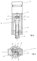
Figure 1 schematically illustrates the drive mechanism according to the present invention in a longitudinal cross section, -
Figure 2 is illustrative of the drive mechanism according toFigure 1 along a cross section A-D as indicated inFigure 1 , -
Figure 3 shows a cross section along E-F as depicted inFigure 1 , and -
Figure 4 illustrates an enlarged cross section of a latching mechanism. - As illustrated in
Figures 1 to 4 , theillustrated drive mechanism 10 is adapted to be used and implemented with a drug delivery device, in particular with a pen-type injector. Theillustrated drive mechanism 10 comprises ahousing nut 26, apiston rod 12 is axially guided. Thepiston rod 12 is in turn adapted to become engaged with a piston of a medicament-filled cartridge, which is not explicitly illustrated here. As illustrated, the housing comprises adistal housing section 24 and aproximal housing section 22, which may be separately or integrally formed. - The
piston rod 12 is typically threadedly engaged with thenut 26 but may also be rotatably locked to thenut 26, e.g. when thepiston rod 12 comprises an axial groove or protrusion corresponding with a respective radially directed protrusion or groove of thenut 26. Therefore, mutual engagement ofnut 26 andpiston rod 12 may support or inhibit rotational movement of thepiston rod 12 relative to the housing in the course of an axial displacement. - As further illustrated, the
piston rod 12 is threadedly engaged with adrive sleeve 14, which, at its proximal end, facing upward inFigures 2 and 3 , is connected or integrally formed with adrive member 15. Thedrive member 15, typically designed as a gear with a circumferential toothing meshes with respective geared ortoothed sections lateral protrusions dose buttons Figures 1 and3 . - Here, the laterally extending and rather rectangularly shaped
protrusions toothed side surface drive member 15. The mechanical coupling of thelateral protrusions drive member 15 and/or a mechanical connection betweendrive member 15 and drive shaft or drivesleeve 14 is unidirectional. Hence, when theprotrusions respective dose buttons drive sleeve 14 remains substantially unaffected. - However, in the opposite direction, when an externally applied actuation force depresses the two
dose buttons portions drive member 15 and/or its associateddrive sleeve 14 is active in order to transfer the radially inwardly directed displacement of thedose button drive sleeve 14. By way of a respective threaded engagement ofdrive sleeve 14 andpiston rod 12, thepiston rod 12 becomes respectively displaced in distal direction for the purpose of dispensing a predefined dose of the medicament. - In
Figure 2 , saidlateral protrusions Fig. 1 . As shown here, thelateral protrusions respective dose buttons drive member 15 by way of radially inwardly facingtoothed sections - Further, with reference to
Figures 1 and3 , the purely radiallydisplaceable dose buttons housing upper housing section 22 is further adapted to receive anactivation button 20. Depressing saidactivation button 20 against the action of a flexibly deformable latchingmember 28 releases thedose buttons - As further illustrated in the enlarged view according to
Figure 4 , the latching means 28 comprises at least a radially and proximally protrudingtongue 28 elastically deformable in axial direction. In its interlock configuration as shown inFigure 4 , thetongue 28 with its free and radially outwardly protruding end section buts against an inward facing side wall section of thehousing section 22. As soon as theactivation button 20 is depressed by an external force as illustrated by the arrow inFigure 4 , the radially and proximally protruding free end of said tongue orflap 28 becomes elastically deformed in distal direction. This way said radial abutment can be abrogated and thedose buttons tongue 28 enters the axial slit betweenhousing 22 anddose button -
- 10
- drive mechanism
- 12
- piston rod
- 14
- drive sleeve
- 15
- drive member
- 16
- protrusion
- 17
- protrusion
- 18
- dose button
- 19
- dose button
- 20
- activation button
- 22
- housing
- 24
- housing
- 26
- nut/guiding element
- 28
- interlock/latching member
- 30
- pin
- 32
- toothed surface
- 34
- toothed surface
or an Exendin-4 derivative of the sequence
Claims (13)
- Drive mechanism of a drug delivery device for dispensing of a dose of a medicament, comprising:- a housing (22, 24) of substantially cylindrical geometry having a long axis extending in an axial direction,- an at least axially displaceable piston rod (12) adapted to become operably engaged with a piston of a cartridge containing the medicament for displacing the piston in a distal direction,- at least one actuation means (18, 19) radially displaceable with respect to the housing (22, 24) by an externally applied depressing force for transferring a respective driving force to the piston rod (12), and- a coupling means operably engaged with the actuation means (18, 19) and with the piston rod (12) adapted to transfer the radially inwardly directed displacement of the at least one actuation means (18, 19) into a distally directed axial displacement of the piston rod (12).
- The drive mechanism according to any one of the preceding claims, wherein the coupling means comprises a drive member (15) threadedly engaged with the piston rod (12) or with a drive sleeve (14).
- The drive mechanism according to any one of the preceding claims, wherein the at least one actuation means (18, 19) comprises a toothed section engaged with an outer gearing of the drive member (15) or of the piston rod (12).
- The drive mechanism according to any one of the preceding claims, wherein the drive sleeve (14) and/or drive member (15) is axially fixed and rotatably mounted in the housing (22, 24).
- The drive mechanism according to any one of the preceding claims, wherein the drive sleeve (14) is threadedly engaged with the piston rod (12) being rotatably fixed and axially displaceable with respect to the housing (22, 24).
- The drive mechanism according to any one of the preceding claims, wherein the actuation means (18, 19) and the drive sleeve (14) are unidirectionally coupled with respect to each other in such a way that only a radially inwardly directed displacement of the actuation means (18, 19) has a rotational effect on the drive sleeve (14).
- The drive mechanism according to any one of the preceding claims, wherein the at least one actuation means (18, 19) is spring biased radially outwardly.
- The drive mechanism according to any one of the preceding claims, wherein the actuation means comprises two diametrically opposed dose buttons (18, 19) protruding from a lateral side wall of the housing (22, 24) in an activation position.
- The drive mechanism according to any one of the preceding claims, wherein the dose buttons (18, 19) comprise a radially inwardly facing, toothed protrusion (32, 34) meshing with diametrically opposite geared sections of the drive member (15).
- The drive mechanism according to any one of the preceding claims, wherein the at least one actuation means (18, 19) is locked in position in a radial inward end position by means of at least one interlock member (28).
- The drive mechanism according to claim 10, wherein the interlock member (28) comprises a radially outwardly protruding tongue (28) flexibly deformable in axial direction and being adapted to but against an inward facing side wall section of the housing (22, 24) in radial direction when the dose button (18, 19) is in its end position.
- The drive mechanism acording to any one of the preceding claims, wherein an activation means (20) is axially displacably mounted at a proximal end section of the housing (22, 24) for axially depressing the free end of the tongue (28) into a release configuration.
- A drug delivery device for dispensing a dose of a medicament comprising:- a drive mechanism according to any one of the preceding claims, and- a cartridge comprising a movable piston to be engaged with a piston rod of the drive mechanism, the piston sealing an inner volume of the cartridge being at least partially filled with the medicament.
Priority Applications (2)
| Application Number | Priority Date | Filing Date | Title |
|---|---|---|---|
| EP10191803A EP2455122A1 (en) | 2010-11-19 | 2010-11-19 | Drive mechanism for a drug delivery device |
| US13/290,895 US8783525B2 (en) | 2010-11-19 | 2011-11-07 | Drive mechanism for a drug delivery device |
Applications Claiming Priority (1)
| Application Number | Priority Date | Filing Date | Title |
|---|---|---|---|
| EP10191803A EP2455122A1 (en) | 2010-11-19 | 2010-11-19 | Drive mechanism for a drug delivery device |
Publications (1)
| Publication Number | Publication Date |
|---|---|
| EP2455122A1 true EP2455122A1 (en) | 2012-05-23 |
Family
ID=43971616
Family Applications (1)
| Application Number | Title | Priority Date | Filing Date |
|---|---|---|---|
| EP10191803A Withdrawn EP2455122A1 (en) | 2010-11-19 | 2010-11-19 | Drive mechanism for a drug delivery device |
Country Status (2)
| Country | Link |
|---|---|
| US (1) | US8783525B2 (en) |
| EP (1) | EP2455122A1 (en) |
Cited By (4)
| Publication number | Priority date | Publication date | Assignee | Title |
|---|---|---|---|---|
| CN105983458A (en) * | 2015-01-28 | 2016-10-05 | 锺官荣 | Sucking type quantitative medicine-dispensing, taking and placing device |
| CN105983459A (en) * | 2015-02-15 | 2016-10-05 | 锺官荣 | Centrifugal quantitative medicine dispensing, taking and placing device |
| TWI555578B (en) * | 2015-01-20 | 2016-11-01 | Kuan-Jung Chung | Extraction of quantitative dosages |
| CN114761057A (en) * | 2019-12-06 | 2022-07-15 | 赛诺菲 | Dosing mechanism with end-of-rotation stop mechanism for ending dose dispensing |
Citations (5)
| Publication number | Priority date | Publication date | Assignee | Title |
|---|---|---|---|---|
| US4641766A (en) * | 1984-11-02 | 1987-02-10 | Alcon Laboratories, Inc. | Metering dispenser for high viscosity compositions |
| WO1999038554A1 (en) * | 1998-01-30 | 1999-08-05 | Novo Nordisk A/S | An injection syringe |
| WO2005037352A2 (en) * | 2003-10-16 | 2005-04-28 | Nps Pharmaceuticals, Inc. | Methods of administering therapeutic injections |
| WO2007092929A2 (en) * | 2006-02-09 | 2007-08-16 | Aderans Research Institute, Inc. | Apparatus and methods for delivering fluid and material to a subject |
| US20080114305A1 (en) * | 2004-08-10 | 2008-05-15 | Gerondale Scott J | Botox® Injector |
Family Cites Families (19)
| Publication number | Priority date | Publication date | Assignee | Title |
|---|---|---|---|---|
| US2086462A (en) * | 1936-07-18 | 1937-07-06 | David E Bost | Dental instrument |
| US4368830A (en) * | 1980-12-18 | 1983-01-18 | Diamond International Corporation | Locking means for liquid dispensers |
| US4710178A (en) * | 1982-11-03 | 1987-12-01 | Micro-Mega S.A. | Precision injection system and method for intraligmental anesthesia |
| US4658993A (en) * | 1984-11-02 | 1987-04-21 | Alcon Laboratories, Inc. | Metering dispenser for viscous compositions |
| US4865231A (en) * | 1987-10-15 | 1989-09-12 | The Procter & Gamble Company | Button type dispensing package |
| US5320259A (en) * | 1992-11-09 | 1994-06-14 | Primary Delivery Systems, Inc. | Vertical ratchet dispenser with hinged trigger |
| DK145792D0 (en) * | 1992-12-03 | 1992-12-03 | Dumex Ltd As | fluid dispensing apparatus |
| US5570821A (en) * | 1995-06-14 | 1996-11-05 | Primary Delivery Systems, Inc. | Vertical ratchet dispenser device with anti-oozing pull-back mechanism |
| US6357945B1 (en) * | 1998-01-21 | 2002-03-19 | Colgate Palmolive Company | Cosmetic dispenser |
| SE9901736D0 (en) * | 1999-05-12 | 1999-05-12 | Pharmacia & Upjohn Ab | Injectino device and method for ITS operation |
| FR2818963B1 (en) * | 2001-01-04 | 2003-04-11 | Valois Sa | COMBIDOSE TYPE FLUID PRODUCT DISPENSING DEVICE |
| DE10121381C1 (en) * | 2001-05-02 | 2002-10-24 | Henkel Kgaa | Dispensing device for a cream-shaped or ablative mass |
| JP4503455B2 (en) * | 2005-02-08 | 2010-07-14 | 株式会社ジーシー | Dental viscous material dispenser |
| EP1714667A1 (en) * | 2005-04-20 | 2006-10-25 | Medisize Schweiz AG | Dosing system with dripper or spray and two articulated arms and method of fabrication |
| JP4994370B2 (en) * | 2005-07-08 | 2012-08-08 | ノボ・ノルデイスク・エー/エス | Injection device |
| DE102006018827A1 (en) * | 2006-04-22 | 2007-10-31 | Bayer Healthcare Ag | Applicator with replaceable container |
| US20080041880A1 (en) * | 2006-06-05 | 2008-02-21 | Roger Babineau | Handheld foodstuff dispenser |
| US20080131191A1 (en) * | 2006-08-29 | 2008-06-05 | Innovative Consumer Solutions, Llc | Spreadable fluid material dispenser apparatus |
| US20130046250A1 (en) * | 2009-12-02 | 2013-02-21 | Sanofi-Aventis Deutschland Gmbh | Drive Mechanism for Drug Delivery Devices |
-
2010
- 2010-11-19 EP EP10191803A patent/EP2455122A1/en not_active Withdrawn
-
2011
- 2011-11-07 US US13/290,895 patent/US8783525B2/en active Active
Patent Citations (5)
| Publication number | Priority date | Publication date | Assignee | Title |
|---|---|---|---|---|
| US4641766A (en) * | 1984-11-02 | 1987-02-10 | Alcon Laboratories, Inc. | Metering dispenser for high viscosity compositions |
| WO1999038554A1 (en) * | 1998-01-30 | 1999-08-05 | Novo Nordisk A/S | An injection syringe |
| WO2005037352A2 (en) * | 2003-10-16 | 2005-04-28 | Nps Pharmaceuticals, Inc. | Methods of administering therapeutic injections |
| US20080114305A1 (en) * | 2004-08-10 | 2008-05-15 | Gerondale Scott J | Botox® Injector |
| WO2007092929A2 (en) * | 2006-02-09 | 2007-08-16 | Aderans Research Institute, Inc. | Apparatus and methods for delivering fluid and material to a subject |
Non-Patent Citations (2)
| Title |
|---|
| "Remington's Pharmaceutical Sciences", 1985, MARK PUBLISHING COMPANY |
| "Rote Liste", 2008 |
Cited By (6)
| Publication number | Priority date | Publication date | Assignee | Title |
|---|---|---|---|---|
| TWI555578B (en) * | 2015-01-20 | 2016-11-01 | Kuan-Jung Chung | Extraction of quantitative dosages |
| CN105983458A (en) * | 2015-01-28 | 2016-10-05 | 锺官荣 | Sucking type quantitative medicine-dispensing, taking and placing device |
| CN105983459A (en) * | 2015-02-15 | 2016-10-05 | 锺官荣 | Centrifugal quantitative medicine dispensing, taking and placing device |
| CN105983459B (en) * | 2015-02-15 | 2018-03-30 | 锺官荣 | Centrifugal quantitative medicine dispensing, taking and placing device |
| CN114761057A (en) * | 2019-12-06 | 2022-07-15 | 赛诺菲 | Dosing mechanism with end-of-rotation stop mechanism for ending dose dispensing |
| US12465692B2 (en) | 2019-12-06 | 2025-11-11 | Sanofi | Dosing mechanism with rotational end stop mechanism for terminating dose dispense |
Also Published As
| Publication number | Publication date |
|---|---|
| US20120148425A1 (en) | 2012-06-14 |
| US8783525B2 (en) | 2014-07-22 |
Similar Documents
| Publication | Publication Date | Title |
|---|---|---|
| EP3662947B1 (en) | Drug delivery device with adjustable piston rod assembly | |
| EP2480276B1 (en) | Assembly for a drug delivery device and drug delivery device | |
| EP3643347B1 (en) | Drug delivery device with an improved piston rod | |
| AU2010255816B2 (en) | Spindle and bearing combination and drug delivery device | |
| AU2010302982B2 (en) | Drive mechanism for a drug delivery device | |
| EP2462971A1 (en) | Needle assembly for drug delivery devices | |
| US20120172818A1 (en) | Medical Device Having a Mechanism and Use of a Low-Friction Synthetic Material Within a Medical Device | |
| US20130046250A1 (en) | Drive Mechanism for Drug Delivery Devices | |
| US8783525B2 (en) | Drive mechanism for a drug delivery device | |
| US20130261552A1 (en) | Drug delivery device with housing comprising frangible zone | |
| EP2731650B1 (en) | Drive mechanism of a drug delivery device | |
| HK1173686A (en) | Assembly for a drug delivery device and drug delivery device | |
| HK1173686B (en) | Assembly for a drug delivery device and drug delivery device | |
| HK40026798B (en) | Drug delivery device with an improved piston rod | |
| HK40026798A (en) | Drug delivery device with an improved piston rod | |
| HK1164175B (en) | Drug delivery device with an improved piston rod | |
| HK1164175A (en) | Drug delivery device with an improved piston rod |
Legal Events
| Date | Code | Title | Description |
|---|---|---|---|
| PUAI | Public reference made under article 153(3) epc to a published international application that has entered the european phase |
Free format text: ORIGINAL CODE: 0009012 |
|
| AK | Designated contracting states |
Kind code of ref document: A1 Designated state(s): AL AT BE BG CH CY CZ DE DK EE ES FI FR GB GR HR HU IE IS IT LI LT LU LV MC MK MT NL NO PL PT RO RS SE SI SK SM TR |
|
| AX | Request for extension of the european patent |
Extension state: BA ME |
|
| RIN1 | Information on inventor provided before grant (corrected) |
Inventor name: MARIAMI, FAIZA |
|
| 17P | Request for examination filed |
Effective date: 20121123 |
|
| STAA | Information on the status of an ep patent application or granted ep patent |
Free format text: STATUS: THE APPLICATION HAS BEEN WITHDRAWN |
|
| 18W | Application withdrawn |
Effective date: 20150630 |