EP2454466B1 - Moteur-fusée à ergols cryotechniques - Google Patents
Moteur-fusée à ergols cryotechniques Download PDFInfo
- Publication number
- EP2454466B1 EP2454466B1 EP10752035.5A EP10752035A EP2454466B1 EP 2454466 B1 EP2454466 B1 EP 2454466B1 EP 10752035 A EP10752035 A EP 10752035A EP 2454466 B1 EP2454466 B1 EP 2454466B1
- Authority
- EP
- European Patent Office
- Prior art keywords
- rocket engine
- nozzle
- engine according
- heater device
- tank
- Prior art date
- Legal status (The legal status is an assumption and is not a legal conclusion. Google has not performed a legal analysis and makes no representation as to the accuracy of the status listed.)
- Active
Links
Images

Classifications
-
- F—MECHANICAL ENGINEERING; LIGHTING; HEATING; WEAPONS; BLASTING
- F02—COMBUSTION ENGINES; HOT-GAS OR COMBUSTION-PRODUCT ENGINE PLANTS
- F02K—JET-PROPULSION PLANTS
- F02K9/00—Rocket-engine plants, i.e. plants carrying both fuel and oxidant therefor; Control thereof
- F02K9/97—Rocket nozzles
- F02K9/972—Fluid cooling arrangements for nozzles
-
- F—MECHANICAL ENGINEERING; LIGHTING; HEATING; WEAPONS; BLASTING
- F02—COMBUSTION ENGINES; HOT-GAS OR COMBUSTION-PRODUCT ENGINE PLANTS
- F02K—JET-PROPULSION PLANTS
- F02K9/00—Rocket-engine plants, i.e. plants carrying both fuel and oxidant therefor; Control thereof
- F02K9/42—Rocket-engine plants, i.e. plants carrying both fuel and oxidant therefor; Control thereof using liquid or gaseous propellants
- F02K9/44—Feeding propellants
- F02K9/50—Feeding propellants using pressurised fluid to pressurise the propellants
-
- F—MECHANICAL ENGINEERING; LIGHTING; HEATING; WEAPONS; BLASTING
- F02—COMBUSTION ENGINES; HOT-GAS OR COMBUSTION-PRODUCT ENGINE PLANTS
- F02K—JET-PROPULSION PLANTS
- F02K9/00—Rocket-engine plants, i.e. plants carrying both fuel and oxidant therefor; Control thereof
- F02K9/42—Rocket-engine plants, i.e. plants carrying both fuel and oxidant therefor; Control thereof using liquid or gaseous propellants
- F02K9/60—Constructional parts; Details not otherwise provided for
- F02K9/62—Combustion or thrust chambers
- F02K9/64—Combustion or thrust chambers having cooling arrangements
Definitions
- the subject of the present invention is a cryogenic propellant rocket engine comprising at least a first reservoir for a first liquid propellant, a second reservoir for a second liquid propellant, a third reservoir for an inert fluid and an axisymmetric nozzle comprising a chamber. combustion, an injection device of the first and second liquid propellant in the combustion chamber, a nozzle neck and a divergent.
- heat exchangers are often used in the industry, which use to heat a fluid the available power of a material part which is recovered either by conduction (contact between two parts) or by convection (contact between a hot fluid and a wall).
- the invention aims to remedy the aforementioned drawbacks of the prior art and to make it possible to recover, in an optimized and simple manner, the heat available in a rocket engine for heating an inert fluid. pressurizing one or more propellant tanks and thus reduce the weight embedded in the launcher equipped with the rocket engine.
- the radiative power emitted by a composite rocket engine nozzle divergent can be greater than 250 kW per m 2 of divergent and it is thus possible to recover a significant radiative energy to heat the inert fluid (for example helium available at 20 k) and thus pressurize a launcher stage to obtain a direct gain on the payload (of the order of several tens of kilograms), without necessarily implementing a recovery of the energy of the rocket engine by conduction or convection.
- inert fluid for example helium available at 20 k
- the heating device comprises a metal structure in which circulates the inert fluid to be heated and a thin layer which is highly absorptive from a thermal radiation point of view is deposited at least on the walls located opposite screw of the nozzle constituting a source of radiative power.
- the plate of the heater device may have a thickness of between about 5 and 15 mm.
- the plate of the heater device advantageously comprises a network of continuous channels of rectangular or circular section.
- the inert fluid is advantageously helium which can serve as a pressurizing gas for example for a liquid oxygen tank.
- connecting pipes are arranged between the heater and the liquid oxygen tank to provide the latter with pressurizing helium.
- the nozzle of the rocket engine can be produced in a wide variety of ways and may for example comprise a deployable diverging which may advantageously be made of carbon-carbon composite material.
- wall 47 of the nozzle 40 to circulate along it in a network of tubes constituting a regenerative circuit 85 which lowers the temperature of the walls 47 of the upper part of the divergent 43, the nozzle neck 42 and the combustion chamber 41 by heating the fuel propellant which is removed from the regenerative circuit 85 by a pipe 86.
- Turbines 87, 77 forming part of the turbo-pumps for pumping the fuel propellant pump 83 and the pumping of the combustion propellant by the pump 73 receive via pipes 86, 97, 98 the propellant which is gasified by the regenerative circuit 85 and which at the outlet of the turbines 87, 77 is evacuated via a duct 99 to the chamber of Combustion 41. All the flow of the propellant fuel flowing in the pipe 86, is injected by the injector 45 in the combustion chamber 41.
- the propellant propellant pumped into the propellant tank 70 is pumped through a pipe 72 and a valve 71 using the pump 73 and leads through the pipe 74 to an injector 44 to be injected into the combustion chamber 41.
- the regenerative circuit 85 may consist of a network of metal tubes attached to a shell constituting the wall of the combustion chamber and all or part of the nozzle of the rocket engine.
- the invention is not limited to nozzles incorporating the regenerative circuit 85 which is only given by way of example.
- the invention applies to all types of divergents 43, and can be applied for example to a rocket engine comprising a sheet of cooling tubes juxtaposed, welded or brazed, and directly constituting at least a portion of the diverging portion of the nozzle.
- the invention applies in a preferred manner to diverging thermostructural composite material, for example of the carbon-carbon, carbon-ceramic or ceramic-ceramic type, these divergents may or may not be of deployable type.
- the invention can also be applied to a rocket engine operating with another type of cooling circuit, for example an auxiliary hydraulic circuit separate from the main engine propellant feed streams.
- the rocket engine when the rocket engine is in operation, it emits a strong heat radiation to the outside.
- the power emitted by the divergent 43 is generally greater than 250 kW per m 2 of divergent.
- a heating device 20 comprising at least one duct traversed by an inert fluid is disposed outside the nozzle 40, in the immediate vicinity thereof, but without contact, to recover the energy of the radiation. thermal emitted when the rocket engine is in operation and heat this inert fluid, which may be for example helium.
- a helium reservoir 60 which is connected by a pipe 62 and a valve 61 to the heater device 20 and a pipe 63 which connects the heater device to the tank 70 of liquid oxygen to supply the latter with helium of pressurizing the tank 70.
- FIG. 4 there is shown a heater device 20 with a frustoconical sector-shaped plate provided with channels 22, but various embodiments are possible for this radiative heat exchanger which makes it possible to recover the radiative energy of the rocket motor and thus of pressurizing one or more propellant tanks by gaining several tens of kilograms on the payload as compared to conventional helium pressurization systems not using a radiative heat exchanger.
- the heater recovering the radiative energy from a rocket engine is composed of a metal structure in which circulates the fluid that is to be heated.
- This heater is sized according to the available radiative power that it is able to absorb at its location. At iso-geometry, its absorption power depends both on its absorptive properties and on the overall view factor between the heater and the rocket motor. For this reason, a thin layer, highly absorptive from a thermal radiation point of view, is deposited on the walls opposite the radiative power source. The high absorptivity of the deposit makes it possible not to think too much of incident flux from the rocket engine to avoid creating an overheating point.
- the fluid circulating in the exchanger is heated by conventional convection allowing at the same time to stabilize the temperature of the walls of the heater.
- the heater device 20 comprises a sector-shaped metal plate frustoconical extending around the divergent nozzle (shown schematically by a truncated cone 30 on the Figures 1 and 3 ) on an angle ⁇ between 30 ° and 360 °.
- the plate 21 of the heater 20 comprises a network of continuous channels 22 of rectangular or circular section.
- a thin layer 23 of high thermal radiation absorbing material is formed on the wall of the plate 21 facing the radiative power source 30.
- the plate 21 of the heater 20 may have a thickness of between about 5 and 15 mm.
Landscapes
- Engineering & Computer Science (AREA)
- Chemical & Material Sciences (AREA)
- Combustion & Propulsion (AREA)
- Mechanical Engineering (AREA)
- General Engineering & Computer Science (AREA)
- Filling Or Discharging Of Gas Storage Vessels (AREA)
- Jet Pumps And Other Pumps (AREA)
Description
- La présente invention a pour objet un moteur-fusée à ergols cryotechniques comprenant au moins un premier réservoir pour un premier ergol liquide, un deuxième réservoir pour un deuxième ergol liquide, un troisième réservoir pour un fluide inerte et une tuyère de forme axisymétrique comprenant une chambre de combustion, un dispositif d'injection des premier et deuxième ergols liquides dans la chambre de combustion, un col de tuyère et un divergent.
- On connaît déjà notamment par le document de brevet
US 6 658 863 un système de stockage et de fourniture de gaz inerte sous pression, tel que de l'hélium, à bord d'un véhicule lanceur à moteur fusée, afin de mettre sous pression un ou plusieurs réservoirs de propergol pour fournir en continu du propergol au moteur-fusée et pour maintenir l'intégrité structurale des réservoirs. Un tel système connu met en oeuvre un échangeur de chaleur qui peut utiliser comme source de chaleur les gaz chauds issus du système de propulsion du lanceur. Il est également proposé d'utiliser un chauffage électrique à titre d'alternative. De telles solutions ne conviennent pas à tous les types de moteur-fusée et de divergent et sont en particulier mal adaptées pour récupérer l'énergie des moteurs-fusées fonctionnant selon un cycle de type expander ou mettant en oeuvre des divergents en matériau composite. - D'une manière générale, on utilise souvent dans l'industrie des échangeurs de chaleur qui utilisent pour réchauffer un fluide la puissance disponible d'une pièce matérielle qui est récupérée soit par conduction (contact entre deux pièces) soit par convection (contact entre un fluide chaud et une paroi).
- L'invention vise à remédier aux inconvénients précités de l'art antérieur et à permettre de récupérer de façon optimisée et simple de la chaleur disponible dans un moteur-fusée pour réchauffer un fluide inerte de pressurisation d'un ou plusieurs réservoirs d'ergol et ainsi réduire la masse embarquée dans le lanceur équipé du moteur-fusée.
- Ces buts sont atteints, conformément à l'invention, grâce à un moteur-fusée à ergols cryotechniques selon la revendication 1.
- La puissance radiative émise par un divergent de tuyère de moteur-fusée en matériau composite peut être supérieure à 250 kW par m2 de divergent et il est ainsi possible de récupérer une énergie radiative importante pour réchauffer le fluide inerte (par exemple de l'hélium disponible à 20 k) et pressuriser ainsi un étage de lanceur pour obtenir un gain direct sur la charge utile (de l'ordre de plusieurs dizaines de kilogrammes), sans mettre nécessairement en oeuvre une récupération de l'énergie du moteur-fusée par conduction ou convection.
- Selon un aspect de l'invention, le dispositif réchauffeur comprend une structure métallique dans laquelle circule le fluide inerte à réchauffer et une fine couche fortement absorptive d'un point de vue rayonnement thermique est déposée au moins sur les parois situées en vis-à-vis de la tuyère constituant une source de puissance radiative.
- La plaque du dispositif réchauffeur peut présenter une épaisseur comprise entre environ 5 et 15 mm.
- La plaque du dispositif réchauffeur comprend avantageusement un réseau de canaux continus de section rectangulaire ou circulaire.
- Le fluide inerte est avantageusement de l'hélium qui peut servir de gaz de pressurisation par exemple pour un réservoir d'oxygène liquide. Dans ce cas, des canalisations de liaison sont disposées entre le dispositif réchauffeur et le réservoir d'oxygène liquide pour fournir à ce dernier de l'hélium de pressurisation.
- La tuyère du moteur-fusée peut être réalisée de façons très diverses et peut par exemple comprendre un divergent déployable qui peut avantageusement être réalisé en matériau composite carbone-carbone.
- D'autres caractéristiques et avantages de l'invention ressortiront de la description suivante de modes particuliers de réalisation, donnés à titre d'exemples, en référence aux dessins annexés, sur lesquels :
- la
figure 1 est une vue schématique en coupe transversale d'une tuyère de moteur-fusée et d'un dispositif réchauffeur à plaque selon un mode de réalisation de l'invention, - la
figure 2 est une vue agrandie, d'une portion II du dispositif réchauffeur à plaque de lafigure 1 ; - la
figure 3 est une vue schématique en perspective de la tuyère et du dispositif réchauffeur à plaque de lafigure 1 ; et - la
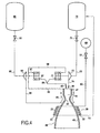
figure 4 est une vue schématique d'ensemble d'un exemple de moteur-fusée auquel est applicable l'invention. - On décrira d'abord brièvement en référence à la
figure 4 un exemple de moteur-fusée à cycle expander auquel est notamment applicable l'invention. - Un flux de combustible, tel que de l'hydrogène, stocké dans un réservoir 80, est pompé dans le réservoir à travers une canalisation 82 et une vanne 81 à l'aide d'une pompe 83 et conduit à travers une canalisation 84 vers la paroi 47 de la tuyère 40 pour circuler le long de celle-ci dans un réseau de tubes constituant un circuit régénératif 85 qui abaisse la température des parois 47 de la partie supérieure du divergent 43, du col de tuyère 42 et de la chambre de combustion 41 en réchauffant l'ergol combustible qui est évacué du circuit régénératif 85 par une canalisation 86. Des turbines 87, 77 faisant partie des turbo-pompes permettant le pompage de l'ergol combustible par la pompe 83 et le pompage de l'ergol comburant par la pompe 73 reçoivent par des canalisations 86, 97, 98 l'ergol qui est gazéifié par le circuit régénératif 85 et qui à la sortie des turbines 87, 77 est évacué par un conduit 99 vers la chambre de combustion 41. Tout le débit de l'ergol combustible circulant dans la canalisation 86, est injecté par l'injecteur 45 dans la chambre de combustion 41. L'ergol comburant pompé dans le réservoir d'ergol 70 est pompé à travers une canalisation 72 et une vanne 71 à l'aide de la pompe 73 et conduit à travers la canalisation 74 vers un injecteur 44 pour être injecté dans la chambre de combustion 41.
- De manière classique, le circuit régénératif 85 peut être constitué par un réseau de tubes métalliques rapportés sur une coque constituant la paroi de la chambre de combustion et de tout ou partie de la tuyère du moteur-fusée.
- L'invention n'est pas limitée à des tuyères incorporant le circuit régénératif 85 qui n'est donné qu'à titre d'exemple.
- L'invention s'applique à tous les types de divergents 43, et peut s'appliquer par exemple à un moteur-fusée comprenant une nappe de tubes de refroidissement juxtaposés, soudés ou brasés, et constituant directement au moins une partie du divergent de la tuyère. Toutefois, l'invention s'applique de façon privilégiée à des divergents en matériau composite thermostructural, par exemple de type carbone-carbone, carbone-céramique ou céramique-céramique, ces divergents pouvant être ou non de type déployable.
- L'invention peut aussi s'appliquer à un moteur-fusée fonctionnant avec un autre type de circuit de refroidissement, par exemple un circuit hydraulique auxiliaire distinct des flux principaux d'ergols d'alimentation du moteur.
- Dans le cas d'un divergent 43 non refroidi et en matériau composite, lorsque le moteur-fusée est en fonctionnement, celui-ci émet un fort rayonnement thermique vers l'extérieur. La puissance émise par le divergent 43 est généralement supérieure à 250 kW par m2 de divergent.
- Conformément à l'invention, un dispositif réchauffeur 20 comprenant au moins un conduit parcouru par un fluide inerte est disposé à l'extérieur de la tuyère 40, à proximité immédiate de celle-ci, mais sans contact, pour récupérer l'énergie du rayonnement thermique émis lorsque le moteur-fusée est en fonctionnement et réchauffer ce fluide inerte, qui peut être par exemple de l'hélium.
- Sur la
figure 4 , on voit un réservoir d'hélium 60 qui est relié par une conduite 62 et une vanne 61 au dispositif réchauffeur 20 et une conduite 63 qui relie le dispositif réchauffeur au réservoir 70 d'oxygène liquide pour fournir à ce dernier de l'hélium de pressurisation du réservoir 70. - Sur la
figure 4 , on a représenté un dispositif réchauffeur 20 avec une plaque en forme de secteur tronconique munie de canaux 22, mais divers modes de réalisation sont possibles pour cet échangeur de chaleur radiatif qui permet de récupérer de l'énergie radiative du moteur-fusée et ainsi de pressuriser un ou plusieurs réservoirs d'ergols en obtenant un gain de plusieurs dizaines de kilogrammes sur la charge utile par comparaison avec des systèmes de pressurisation d'hélium classiques n'utilisant pas d'échangeur de chaleur radiatif. - Le réchauffeur récupérant l'énergie radiative provenant d'un moteur-fusée est composé d'une structure métallique dans laquelle circule le fluide que l'on veut réchauffer. Ce réchauffeur est dimensionné en fonction de la puissance radiative disponible qu'il est capable d'absorber à son emplacement. A iso-géométrie, son pouvoir d'absorption dépend à la fois de ses propriétés absorptives et du facteur de vue global entre le réchauffeur et le moteur fusée. Pour cette raison, une fine couche, fortement absorptive d'un point de vue rayonnement thermique, est déposée sur les parois en vis-à-vis de la source de puissance radiative. La forte absorptivité du dépôt permet de ne pas réfléchir trop de flux incident provenant du moteur-fusée pour ne pas créer de point de surchauffe. Le fluide circulant dans l'échangeur se réchauffe par convection classique permettant par la même occasion de stabiliser la température des parois du réchauffeur.
- L'environnement du réchauffeur est composé :
- du vide sidéral (température du vide sidéral à 3K)
- du moteur-fusée lui-même composé d'au moins une pièce, de forme axisymétrique, chaude en fonctionnement (T > 1 000 K).
- Selon un mode de réalisation avantageux, le dispositif réchauffeur 20 comprend une plaque métallique en forme de secteur tronconique qui s'étend autour du divergent de la tuyère (représenté schématiquement par un tronc de cône 30 sur les
figures 1 et 3 ) sur un angle σ compris entre 30° et 360°. - Comme on peut le voir sur la
figure 2 , la plaque 21 du réchauffeur 20 comprend un réseau de canaux continus 22 de section rectangulaire ou circulaire. Une fine couche 23 de matériau fortement absorptif d'un point de vue rayonnement thermique est formée sur la paroi de la plaque 21 située en vis-à-vis de la source de puissance radiative 30. - La plaque 21 du réchauffeur 20 peut présenter une épaisseur comprise entre environ 5 et 15 mm.
Claims (9)
- Moteur-fusée à ergols cryotechniques comprenant au moins un premier réservoir (70) pour un premier ergol liquide, un deuxième réservoir (80) pour un deuxième ergol liquide, un troisième réservoir (60) pour un fluide inerte et une tuyère (40) de forme axisymétrique comprenant une chambre de combustion (41), un dispositif (44, 45) d'injection des premier et deuxième ergols liquides dans la chambre de combustion (41), un col de tuyère (42) et un divergent (43), et en outre un dispositif réchauffeur (20) comprenant au moins un conduit (22) de circulation dudit fluide inerte et disposé à l'extérieur de la tuyère (40) caractérisé en ce que ledit dispositif réchauffeur (20) est disposé à proximité immédiate de ladite tuyère (40) mais sans contact, pour récupérer l'énergie du rayonnement thermique émis lorsque le moteur-fusée est en fonctionnement et réchauffer ledit fluide inerte, le dispositif réchauffeur (20) comprenant une plaque (21) en forme de secteur tronconique qui s'étend autour du divergent (43) de la tuyère (40) sur un angle σ compris entre 30° et 360°.
- Moteur-fusée selon la revendication 1, caractérisé en ce que le dispositif réchauffeur (20) comprend une structure métallique dans laquelle circule le fluide inerte à réchauffer et une fine couche (23) fortement absorptive d'un point de vue rayonnement thermique est déposée au moins sur les parois situées en vis-à-vis de la tuyère constituant une source de puissance radiative.
- Moteur-fusée selon la revendication 1 ou la revendication 2, caractérisé en ce que ladite plaque (21) du dispositif réchauffeur (20) présente une épaisseur comprise entre 5 et 15 mm.
- Moteur-fusée selon l'une quelconque des revendications 1 à 3, caractérisé en ce que ladite plaque (21) du dispositif réchauffeur (20) comprend un réseau de canaux continus (22) de section rectangulaire ou circulaire.
- Moteur-fusée selon l'une quelconque des revendications 1 à 4, caractérisé en ce que le fluide inerte est de l'hélium.
- Moteur-fusée selon l'une quelconque des revendications 1 à 5, caractérisé en ce qu'il comprend au moins un réservoir (70) d'oxygène liquide.
- Moteur-fusée selon les revendications 5 et 6, caractérisé en ce qu'il comprend des canalisations de liaison entre le dispositif réchauffeur (20) et le réservoir (70) d'oxygène liquide pour fournir à ce dernier de l'hélium de pressurisation.
- Moteur-fusée selon l'une quelconque des revendications 1 à 7, caractérisé en ce que la tuyère (40) comprend un divergent (43) déployable.
- Moteur-fusée selon l'une quelconque des revendications 1 à 8, caractérisé en ce qu'il comprend un divergent en matériau composite thermostructural carbone-carbone, carbone-céramique ou céramique-céramique.
Applications Claiming Priority (2)
| Application Number | Priority Date | Filing Date | Title |
|---|---|---|---|
| FR0954984A FR2948152B1 (fr) | 2009-07-17 | 2009-07-17 | Moteur-fusee a ergols cryotechniques |
| PCT/FR2010/051504 WO2011007108A1 (fr) | 2009-07-17 | 2010-07-16 | Moteur-fusee a ergols cryotechniques |
Publications (2)
| Publication Number | Publication Date |
|---|---|
| EP2454466A1 EP2454466A1 (fr) | 2012-05-23 |
| EP2454466B1 true EP2454466B1 (fr) | 2013-07-03 |
Family
ID=41609813
Family Applications (2)
| Application Number | Title | Priority Date | Filing Date |
|---|---|---|---|
| EP10752035.5A Active EP2454466B1 (fr) | 2009-07-17 | 2010-07-16 | Moteur-fusée à ergols cryotechniques |
| EP10752034.8A Active EP2454465B1 (fr) | 2009-07-17 | 2010-07-16 | Moteur-fusée à ergols cryotechniques |
Family Applications After (1)
| Application Number | Title | Priority Date | Filing Date |
|---|---|---|---|
| EP10752034.8A Active EP2454465B1 (fr) | 2009-07-17 | 2010-07-16 | Moteur-fusée à ergols cryotechniques |
Country Status (5)
| Country | Link |
|---|---|
| US (2) | US9222439B2 (fr) |
| EP (2) | EP2454466B1 (fr) |
| JP (2) | JP5685251B2 (fr) |
| FR (1) | FR2948152B1 (fr) |
| WO (2) | WO2011007108A1 (fr) |
Families Citing this family (8)
| Publication number | Priority date | Publication date | Assignee | Title |
|---|---|---|---|---|
| US8572948B1 (en) * | 2010-10-15 | 2013-11-05 | Florida Turbine Technologies, Inc. | Rocket engine propulsion system |
| FR2997731B1 (fr) * | 2012-11-06 | 2018-07-27 | Arianegroup Sas | Dispositif et procede d'alimentation d'un moteur-fusee |
| FR3004368B1 (fr) * | 2013-04-15 | 2015-09-25 | Aircelle Sa | Brasage sans outillage |
| FR3012848B1 (fr) * | 2013-11-06 | 2015-11-27 | Snecma | Ensemble propulsif et procede d'alimentation en ergols |
| US12060853B2 (en) * | 2019-01-30 | 2024-08-13 | Laboratoire Reaction Dynamics Inc. | Rocket engine with integrated oxidizer catalyst in manifold and injector assembly |
| DE102020103791B4 (de) | 2020-02-13 | 2024-07-04 | Arianegroup Gmbh | Düsenkörper mit helixförmigem Kühlkanal, Triebwerk mit Düsenkörper und Verfahren zum Herstellen eines Düsenkörpers |
| KR102468746B1 (ko) | 2020-11-18 | 2022-11-18 | 한국항공우주연구원 | 열교환 구조를 포함하는 연소기 및 이를 포함하는 로켓 |
| CN115217673B (zh) * | 2022-07-11 | 2024-07-26 | 中国人民解放军国防科技大学 | 用于液体火箭发动机试验台的推进剂冷量回收系统及方法 |
Family Cites Families (23)
| Publication number | Priority date | Publication date | Assignee | Title |
|---|---|---|---|---|
| US2991617A (en) * | 1950-12-01 | 1961-07-11 | Gen Electric | Jet motor combustion chamber |
| US2663142A (en) * | 1951-12-20 | 1953-12-22 | Wilson Walter Hobart | Thermojet engine |
| US3246466A (en) * | 1962-02-09 | 1966-04-19 | Gen Motors Corp | Solid-liquid propellant rocket |
| US3220180A (en) * | 1962-04-30 | 1965-11-30 | Marquardt Corp | Radiation cooled rocket thrust motor |
| US3354652A (en) * | 1965-04-23 | 1967-11-28 | Thiokol Chemical Corp | Rocket thrust chamber |
| US3416600A (en) * | 1967-01-23 | 1968-12-17 | Whirlpool Co | Heat exchanger having twisted multiple passage tubes |
| US3543845A (en) * | 1968-09-19 | 1970-12-01 | United Aircraft Prod | Heat exchange apparatus |
| US3630449A (en) * | 1970-05-11 | 1971-12-28 | Us Air Force | Nozzle for rocket engine |
| US4825647A (en) * | 1983-07-26 | 1989-05-02 | Technion, Inc. | Performance improvements in thruster assembly |
| US4785879A (en) * | 1986-01-14 | 1988-11-22 | Apd Cryogenics | Parallel wrapped tube heat exchanger |
| US5048289A (en) * | 1989-06-15 | 1991-09-17 | Rockwell International Corporation | Extendible nozzle |
| US5802842A (en) * | 1996-07-29 | 1998-09-08 | Trw Inc. | Dimensionally stable throat insert for rocket thrusters |
| FR2782378B1 (fr) | 1998-08-14 | 2000-11-10 | Snecma | Piece de structure comportant une partie en materiau composite thermostructural refroidie par circulation de fluide |
| JP2000248994A (ja) * | 1999-03-01 | 2000-09-12 | Ishikawajima Harima Heavy Ind Co Ltd | ロケットエンジンの推薬加圧装置 |
| JP4405630B2 (ja) * | 1999-11-12 | 2010-01-27 | 株式会社Ihiエアロスペース | 液体ロケットエンジンシステムの冷却構成及びその冷却方法 |
| FR2825135A1 (fr) * | 2001-05-22 | 2002-11-29 | Lockheed Corp | Systeme embarque de stockage de gaz et d'alimentation en gaz |
| US6758386B2 (en) * | 2001-09-18 | 2004-07-06 | The Boeing Company | Method of joining ceramic matrix composites and metals |
| WO2003043954A1 (fr) * | 2001-11-19 | 2003-05-30 | Stanton Advanced Ceramics Llc | Composites ceramiques resistant au choc thermique |
| US7216477B1 (en) * | 2002-03-15 | 2007-05-15 | United Technologies Corporation | Method and apparatus for a rocket engine power cycle |
| GB0306179D0 (en) * | 2003-03-18 | 2003-04-23 | Imp College Innovations Ltd | Piping |
| US7784269B1 (en) * | 2006-08-25 | 2010-08-31 | Xcor Aerospace | System and method for cooling rocket engines |
| US7900436B2 (en) * | 2007-07-20 | 2011-03-08 | The United States Of America As Represented By The Administrator Of The National Aeronautics And Space Administration | Gas-generator augmented expander cycle rocket engine |
| JP5711665B2 (ja) * | 2008-12-08 | 2015-05-07 | ファイアースター エンジニアリング,エルエルシー | 多孔質媒体を用いる再生冷却型ジャケット |
-
2009
- 2009-07-17 FR FR0954984A patent/FR2948152B1/fr active Active
-
2010
- 2010-07-16 JP JP2012520078A patent/JP5685251B2/ja not_active Expired - Fee Related
- 2010-07-16 WO PCT/FR2010/051504 patent/WO2011007108A1/fr not_active Ceased
- 2010-07-16 US US13/384,477 patent/US9222439B2/en not_active Expired - Fee Related
- 2010-07-16 WO PCT/FR2010/051503 patent/WO2011007107A1/fr not_active Ceased
- 2010-07-16 EP EP10752035.5A patent/EP2454466B1/fr active Active
- 2010-07-16 EP EP10752034.8A patent/EP2454465B1/fr active Active
- 2010-07-16 US US13/384,469 patent/US9222438B2/en not_active Expired - Fee Related
- 2010-07-16 JP JP2012520077A patent/JP5685250B2/ja not_active Expired - Fee Related
Also Published As
| Publication number | Publication date |
|---|---|
| US9222438B2 (en) | 2015-12-29 |
| JP2012533700A (ja) | 2012-12-27 |
| JP2012533701A (ja) | 2012-12-27 |
| US9222439B2 (en) | 2015-12-29 |
| US20120144797A1 (en) | 2012-06-14 |
| JP5685251B2 (ja) | 2015-03-18 |
| WO2011007108A1 (fr) | 2011-01-20 |
| US20120131903A1 (en) | 2012-05-31 |
| WO2011007107A1 (fr) | 2011-01-20 |
| EP2454465A1 (fr) | 2012-05-23 |
| EP2454466A1 (fr) | 2012-05-23 |
| JP5685250B2 (ja) | 2015-03-18 |
| FR2948152A1 (fr) | 2011-01-21 |
| EP2454465B1 (fr) | 2013-07-03 |
| FR2948152B1 (fr) | 2012-02-03 |
Similar Documents
| Publication | Publication Date | Title |
|---|---|---|
| EP2454465B1 (fr) | Moteur-fusée à ergols cryotechniques | |
| US12467421B2 (en) | Omnivorous solar thermal thruster, cooling systems, and thermal energy transfer in rockets | |
| EP2943676B1 (fr) | Système et procédé d'alimentation d'un moteur-fusée | |
| CN108138697B (zh) | 改善的液氧-液态丙烯火箭发动机 | |
| EP2943675B1 (fr) | Circuit d'alimentation en ergol | |
| FR2698914A1 (fr) | Moteur-fusée à ergols liquides à flux dérivé et générateur de gaz intégré. | |
| EP2925994B1 (fr) | Ensemble propulsif pour fusée | |
| FR2987081A1 (fr) | Ensemble et procede propulsifs | |
| FR2666851A1 (fr) | Moteur a propulsion thermique solaire. | |
| EP4143427B1 (fr) | Propulseur thermique solaire omnivore, systèmes de refroidissement et transfert d'énergie thermique dans des fusées | |
| FR2800131A1 (fr) | Fusees thermiques solaires | |
| FR2835313A1 (fr) | Panneau d'echangeur de chaleur | |
| FR3064031A1 (fr) | Dispositif de chambre de poussee et procede pour faire fonctionner un dispositif de chambre de poussee | |
| FR2640322A1 (fr) | Moteur-fusee ou moteur combine pour vehicule spatial a circuit hydraulique auxiliaire essentiellement ferme | |
| EP0945596A1 (fr) | Structure de protection thermique | |
| FR2656378A1 (fr) | Paroi refroidie pour chambre de combustion ou tuyere de moteur-fusee, moteur aerobie ou moteur combine. | |
| FR3154149A1 (fr) | Ensemble propulsif pour aéronef | |
| CN120576005A (zh) | 一种兼具增效变推、相变热防与红外隐身一体化效能的轻质贮氦喷管 | |
| WO2025219675A1 (fr) | Echangeur thermique double paroi pour un systeme de conditionnement de carburant | |
| FR3159955A1 (fr) | Système de conditionnement de carburant pour alimenter un turbomoteur d’aéronef et procédé associé |
Legal Events
| Date | Code | Title | Description |
|---|---|---|---|
| PUAI | Public reference made under article 153(3) epc to a published international application that has entered the european phase |
Free format text: ORIGINAL CODE: 0009012 |
|
| 17P | Request for examination filed |
Effective date: 20120124 |
|
| AK | Designated contracting states |
Kind code of ref document: A1 Designated state(s): AL AT BE BG CH CY CZ DE DK EE ES FI FR GB GR HR HU IE IS IT LI LT LU LV MC MK MT NL NO PL PT RO SE SI SK SM TR |
|
| DAX | Request for extension of the european patent (deleted) | ||
| GRAP | Despatch of communication of intention to grant a patent |
Free format text: ORIGINAL CODE: EPIDOSNIGR1 |
|
| RIN1 | Information on inventor provided before grant (corrected) |
Inventor name: LE DORTZ, DANIEL Inventor name: DOBEK, OLIVIER |
|
| GRAS | Grant fee paid |
Free format text: ORIGINAL CODE: EPIDOSNIGR3 |
|
| GRAA | (expected) grant |
Free format text: ORIGINAL CODE: 0009210 |
|
| AK | Designated contracting states |
Kind code of ref document: B1 Designated state(s): AL AT BE BG CH CY CZ DE DK EE ES FI FR GB GR HR HU IE IS IT LI LT LU LV MC MK MT NL NO PL PT RO SE SI SK SM TR |
|
| REG | Reference to a national code |
Ref country code: GB Ref legal event code: FG4D Free format text: NOT ENGLISH |
|
| REG | Reference to a national code |
Ref country code: AT Ref legal event code: REF Ref document number: 619935 Country of ref document: AT Kind code of ref document: T Effective date: 20130715 Ref country code: CH Ref legal event code: EP |
|
| REG | Reference to a national code |
Ref country code: IE Ref legal event code: FG4D Free format text: LANGUAGE OF EP DOCUMENT: FRENCH |
|
| REG | Reference to a national code |
Ref country code: DE Ref legal event code: R096 Ref document number: 602010008281 Country of ref document: DE Effective date: 20130829 |
|
| PG25 | Lapsed in a contracting state [announced via postgrant information from national office to epo] |
Ref country code: SI Free format text: LAPSE BECAUSE OF FAILURE TO SUBMIT A TRANSLATION OF THE DESCRIPTION OR TO PAY THE FEE WITHIN THE PRESCRIBED TIME-LIMIT Effective date: 20130703 |
|
| REG | Reference to a national code |
Ref country code: AT Ref legal event code: MK05 Ref document number: 619935 Country of ref document: AT Kind code of ref document: T Effective date: 20130703 |
|
| REG | Reference to a national code |
Ref country code: NL Ref legal event code: VDEP Effective date: 20130703 |
|
| REG | Reference to a national code |
Ref country code: LT Ref legal event code: MG4D |
|
| BERE | Be: lapsed |
Owner name: SNECMA Effective date: 20130731 |
|
| PG25 | Lapsed in a contracting state [announced via postgrant information from national office to epo] |
Ref country code: CY Free format text: LAPSE BECAUSE OF FAILURE TO SUBMIT A TRANSLATION OF THE DESCRIPTION OR TO PAY THE FEE WITHIN THE PRESCRIBED TIME-LIMIT Effective date: 20130828 Ref country code: PT Free format text: LAPSE BECAUSE OF FAILURE TO SUBMIT A TRANSLATION OF THE DESCRIPTION OR TO PAY THE FEE WITHIN THE PRESCRIBED TIME-LIMIT Effective date: 20131104 Ref country code: NO Free format text: LAPSE BECAUSE OF FAILURE TO SUBMIT A TRANSLATION OF THE DESCRIPTION OR TO PAY THE FEE WITHIN THE PRESCRIBED TIME-LIMIT Effective date: 20131003 Ref country code: HR Free format text: LAPSE BECAUSE OF FAILURE TO SUBMIT A TRANSLATION OF THE DESCRIPTION OR TO PAY THE FEE WITHIN THE PRESCRIBED TIME-LIMIT Effective date: 20130703 Ref country code: AT Free format text: LAPSE BECAUSE OF FAILURE TO SUBMIT A TRANSLATION OF THE DESCRIPTION OR TO PAY THE FEE WITHIN THE PRESCRIBED TIME-LIMIT Effective date: 20130703 Ref country code: IS Free format text: LAPSE BECAUSE OF FAILURE TO SUBMIT A TRANSLATION OF THE DESCRIPTION OR TO PAY THE FEE WITHIN THE PRESCRIBED TIME-LIMIT Effective date: 20131103 Ref country code: SE Free format text: LAPSE BECAUSE OF FAILURE TO SUBMIT A TRANSLATION OF THE DESCRIPTION OR TO PAY THE FEE WITHIN THE PRESCRIBED TIME-LIMIT Effective date: 20130703 Ref country code: LT Free format text: LAPSE BECAUSE OF FAILURE TO SUBMIT A TRANSLATION OF THE DESCRIPTION OR TO PAY THE FEE WITHIN THE PRESCRIBED TIME-LIMIT Effective date: 20130703 |
|
| PG25 | Lapsed in a contracting state [announced via postgrant information from national office to epo] |
Ref country code: PL Free format text: LAPSE BECAUSE OF FAILURE TO SUBMIT A TRANSLATION OF THE DESCRIPTION OR TO PAY THE FEE WITHIN THE PRESCRIBED TIME-LIMIT Effective date: 20130703 Ref country code: FI Free format text: LAPSE BECAUSE OF FAILURE TO SUBMIT A TRANSLATION OF THE DESCRIPTION OR TO PAY THE FEE WITHIN THE PRESCRIBED TIME-LIMIT Effective date: 20130703 Ref country code: ES Free format text: LAPSE BECAUSE OF FAILURE TO SUBMIT A TRANSLATION OF THE DESCRIPTION OR TO PAY THE FEE WITHIN THE PRESCRIBED TIME-LIMIT Effective date: 20131014 Ref country code: GR Free format text: LAPSE BECAUSE OF FAILURE TO SUBMIT A TRANSLATION OF THE DESCRIPTION OR TO PAY THE FEE WITHIN THE PRESCRIBED TIME-LIMIT Effective date: 20131004 Ref country code: NL Free format text: LAPSE BECAUSE OF FAILURE TO SUBMIT A TRANSLATION OF THE DESCRIPTION OR TO PAY THE FEE WITHIN THE PRESCRIBED TIME-LIMIT Effective date: 20130703 Ref country code: LV Free format text: LAPSE BECAUSE OF FAILURE TO SUBMIT A TRANSLATION OF THE DESCRIPTION OR TO PAY THE FEE WITHIN THE PRESCRIBED TIME-LIMIT Effective date: 20130703 |
|
| PG25 | Lapsed in a contracting state [announced via postgrant information from national office to epo] |
Ref country code: CY Free format text: LAPSE BECAUSE OF FAILURE TO SUBMIT A TRANSLATION OF THE DESCRIPTION OR TO PAY THE FEE WITHIN THE PRESCRIBED TIME-LIMIT Effective date: 20130703 |
|
| REG | Reference to a national code |
Ref country code: IE Ref legal event code: MM4A |
|
| PG25 | Lapsed in a contracting state [announced via postgrant information from national office to epo] |
Ref country code: EE Free format text: LAPSE BECAUSE OF FAILURE TO SUBMIT A TRANSLATION OF THE DESCRIPTION OR TO PAY THE FEE WITHIN THE PRESCRIBED TIME-LIMIT Effective date: 20130703 Ref country code: DK Free format text: LAPSE BECAUSE OF FAILURE TO SUBMIT A TRANSLATION OF THE DESCRIPTION OR TO PAY THE FEE WITHIN THE PRESCRIBED TIME-LIMIT Effective date: 20130703 Ref country code: CZ Free format text: LAPSE BECAUSE OF FAILURE TO SUBMIT A TRANSLATION OF THE DESCRIPTION OR TO PAY THE FEE WITHIN THE PRESCRIBED TIME-LIMIT Effective date: 20130703 Ref country code: MC Free format text: LAPSE BECAUSE OF FAILURE TO SUBMIT A TRANSLATION OF THE DESCRIPTION OR TO PAY THE FEE WITHIN THE PRESCRIBED TIME-LIMIT Effective date: 20130703 Ref country code: SK Free format text: LAPSE BECAUSE OF FAILURE TO SUBMIT A TRANSLATION OF THE DESCRIPTION OR TO PAY THE FEE WITHIN THE PRESCRIBED TIME-LIMIT Effective date: 20130703 Ref country code: RO Free format text: LAPSE BECAUSE OF FAILURE TO SUBMIT A TRANSLATION OF THE DESCRIPTION OR TO PAY THE FEE WITHIN THE PRESCRIBED TIME-LIMIT Effective date: 20130703 Ref country code: BE Free format text: LAPSE BECAUSE OF NON-PAYMENT OF DUE FEES Effective date: 20130731 |
|
| PLBE | No opposition filed within time limit |
Free format text: ORIGINAL CODE: 0009261 |
|
| STAA | Information on the status of an ep patent application or granted ep patent |
Free format text: STATUS: NO OPPOSITION FILED WITHIN TIME LIMIT |
|
| 26N | No opposition filed |
Effective date: 20140404 |
|
| REG | Reference to a national code |
Ref country code: DE Ref legal event code: R097 Ref document number: 602010008281 Country of ref document: DE Effective date: 20140404 |
|
| PG25 | Lapsed in a contracting state [announced via postgrant information from national office to epo] |
Ref country code: IE Free format text: LAPSE BECAUSE OF NON-PAYMENT OF DUE FEES Effective date: 20130716 |
|
| REG | Reference to a national code |
Ref country code: CH Ref legal event code: PL |
|
| GBPC | Gb: european patent ceased through non-payment of renewal fee |
Effective date: 20140716 |
|
| PG25 | Lapsed in a contracting state [announced via postgrant information from national office to epo] |
Ref country code: CH Free format text: LAPSE BECAUSE OF NON-PAYMENT OF DUE FEES Effective date: 20140731 Ref country code: LI Free format text: LAPSE BECAUSE OF NON-PAYMENT OF DUE FEES Effective date: 20140731 |
|
| PG25 | Lapsed in a contracting state [announced via postgrant information from national office to epo] |
Ref country code: GB Free format text: LAPSE BECAUSE OF NON-PAYMENT OF DUE FEES Effective date: 20140716 Ref country code: SM Free format text: LAPSE BECAUSE OF FAILURE TO SUBMIT A TRANSLATION OF THE DESCRIPTION OR TO PAY THE FEE WITHIN THE PRESCRIBED TIME-LIMIT Effective date: 20130703 |
|
| PG25 | Lapsed in a contracting state [announced via postgrant information from national office to epo] |
Ref country code: MT Free format text: LAPSE BECAUSE OF FAILURE TO SUBMIT A TRANSLATION OF THE DESCRIPTION OR TO PAY THE FEE WITHIN THE PRESCRIBED TIME-LIMIT Effective date: 20130703 Ref country code: TR Free format text: LAPSE BECAUSE OF FAILURE TO SUBMIT A TRANSLATION OF THE DESCRIPTION OR TO PAY THE FEE WITHIN THE PRESCRIBED TIME-LIMIT Effective date: 20130703 |
|
| PG25 | Lapsed in a contracting state [announced via postgrant information from national office to epo] |
Ref country code: HU Free format text: LAPSE BECAUSE OF FAILURE TO SUBMIT A TRANSLATION OF THE DESCRIPTION OR TO PAY THE FEE WITHIN THE PRESCRIBED TIME-LIMIT; INVALID AB INITIO Effective date: 20100716 Ref country code: BG Free format text: LAPSE BECAUSE OF FAILURE TO SUBMIT A TRANSLATION OF THE DESCRIPTION OR TO PAY THE FEE WITHIN THE PRESCRIBED TIME-LIMIT Effective date: 20130703 Ref country code: MK Free format text: LAPSE BECAUSE OF FAILURE TO SUBMIT A TRANSLATION OF THE DESCRIPTION OR TO PAY THE FEE WITHIN THE PRESCRIBED TIME-LIMIT Effective date: 20130703 Ref country code: LU Free format text: LAPSE BECAUSE OF NON-PAYMENT OF DUE FEES Effective date: 20130716 |
|
| REG | Reference to a national code |
Ref country code: FR Ref legal event code: PLFP Year of fee payment: 7 |
|
| REG | Reference to a national code |
Ref country code: FR Ref legal event code: PLFP Year of fee payment: 8 |
|
| REG | Reference to a national code |
Ref country code: DE Ref legal event code: R081 Ref document number: 602010008281 Country of ref document: DE Owner name: ARIANEGROUP SAS, FR Free format text: FORMER OWNER: SNECMA, PARIS, FR |
|
| REG | Reference to a national code |
Ref country code: DE Ref legal event code: R081 Ref document number: 602010008281 Country of ref document: DE Owner name: ARIANEGROUP SAS, FR Free format text: FORMER OWNER: AIRBUS SAFRAN LAUNCHERS SAS, ISSY-LES-MOULINEAUX, FR |
|
| REG | Reference to a national code |
Ref country code: FR Ref legal event code: PLFP Year of fee payment: 9 |
|
| PG25 | Lapsed in a contracting state [announced via postgrant information from national office to epo] |
Ref country code: AL Free format text: LAPSE BECAUSE OF FAILURE TO SUBMIT A TRANSLATION OF THE DESCRIPTION OR TO PAY THE FEE WITHIN THE PRESCRIBED TIME-LIMIT Effective date: 20130703 |
|
| PGFP | Annual fee paid to national office [announced via postgrant information from national office to epo] |
Ref country code: ES Payment date: 20180816 Year of fee payment: 9 |
|
| REG | Reference to a national code |
Ref country code: DE Ref legal event code: R119 Ref document number: 602010008281 Country of ref document: DE |
|
| PG25 | Lapsed in a contracting state [announced via postgrant information from national office to epo] |
Ref country code: DE Free format text: LAPSE BECAUSE OF NON-PAYMENT OF DUE FEES Effective date: 20200201 |
|
| P01 | Opt-out of the competence of the unified patent court (upc) registered |
Effective date: 20230612 |
|
| PGFP | Annual fee paid to national office [announced via postgrant information from national office to epo] |
Ref country code: IT Payment date: 20250724 Year of fee payment: 16 |
|
| PGFP | Annual fee paid to national office [announced via postgrant information from national office to epo] |
Ref country code: FR Payment date: 20250725 Year of fee payment: 16 |