EP2454020B1 - Apparatus and method for the enrichment of magnetic particles - Google Patents
Apparatus and method for the enrichment of magnetic particles Download PDFInfo
- Publication number
- EP2454020B1 EP2454020B1 EP10740362.8A EP10740362A EP2454020B1 EP 2454020 B1 EP2454020 B1 EP 2454020B1 EP 10740362 A EP10740362 A EP 10740362A EP 2454020 B1 EP2454020 B1 EP 2454020B1
- Authority
- EP
- European Patent Office
- Prior art keywords
- pole
- sample
- magnetic
- sample space
- magnetic particles
- Prior art date
- Legal status (The legal status is an assumption and is not a legal conclusion. Google has not performed a legal analysis and makes no representation as to the accuracy of the status listed.)
- Not-in-force
Links
- 239000006249 magnetic particle Substances 0.000 title claims description 41
- 238000000034 method Methods 0.000 title claims description 41
- 230000005291 magnetic effect Effects 0.000 claims description 76
- 239000012530 fluid Substances 0.000 claims description 23
- 238000002360 preparation method Methods 0.000 claims description 17
- 238000013508 migration Methods 0.000 claims description 16
- 230000005012 migration Effects 0.000 claims description 16
- 230000004907 flux Effects 0.000 claims description 13
- 230000005415 magnetization Effects 0.000 claims description 8
- 238000004804 winding Methods 0.000 claims description 4
- 239000000523 sample Substances 0.000 description 84
- 239000011324 bead Substances 0.000 description 24
- 239000002245 particle Substances 0.000 description 20
- 238000001514 detection method Methods 0.000 description 11
- 238000013461 design Methods 0.000 description 10
- 210000004027 cell Anatomy 0.000 description 7
- 230000008569 process Effects 0.000 description 7
- 238000000926 separation method Methods 0.000 description 6
- 230000005284 excitation Effects 0.000 description 4
- 239000000463 material Substances 0.000 description 4
- 238000012360 testing method Methods 0.000 description 4
- 239000012141 concentrate Substances 0.000 description 3
- 230000000694 effects Effects 0.000 description 3
- 238000012545 processing Methods 0.000 description 3
- XEEYBQQBJWHFJM-UHFFFAOYSA-N Iron Chemical compound [Fe] XEEYBQQBJWHFJM-UHFFFAOYSA-N 0.000 description 2
- 241000700605 Viruses Species 0.000 description 2
- 238000004458 analytical method Methods 0.000 description 2
- 230000008901 benefit Effects 0.000 description 2
- 238000011161 development Methods 0.000 description 2
- 230000018109 developmental process Effects 0.000 description 2
- 238000002474 experimental method Methods 0.000 description 2
- 230000002349 favourable effect Effects 0.000 description 2
- 238000003780 insertion Methods 0.000 description 2
- 230000037431 insertion Effects 0.000 description 2
- 230000010354 integration Effects 0.000 description 2
- 238000002032 lab-on-a-chip Methods 0.000 description 2
- 239000006148 magnetic separator Substances 0.000 description 2
- 238000005259 measurement Methods 0.000 description 2
- 150000007523 nucleic acids Chemical class 0.000 description 2
- 102000039446 nucleic acids Human genes 0.000 description 2
- 108020004707 nucleic acids Proteins 0.000 description 2
- 230000003287 optical effect Effects 0.000 description 2
- 238000000746 purification Methods 0.000 description 2
- 239000000243 solution Substances 0.000 description 2
- 241000238366 Cephalopoda Species 0.000 description 1
- RYGMFSIKBFXOCR-UHFFFAOYSA-N Copper Chemical compound [Cu] RYGMFSIKBFXOCR-UHFFFAOYSA-N 0.000 description 1
- 238000007399 DNA isolation Methods 0.000 description 1
- CWYNVVGOOAEACU-UHFFFAOYSA-N Fe2+ Chemical compound [Fe+2] CWYNVVGOOAEACU-UHFFFAOYSA-N 0.000 description 1
- 238000001069 Raman spectroscopy Methods 0.000 description 1
- 238000010521 absorption reaction Methods 0.000 description 1
- 230000003321 amplification Effects 0.000 description 1
- 239000012491 analyte Substances 0.000 description 1
- 238000013459 approach Methods 0.000 description 1
- 239000007864 aqueous solution Substances 0.000 description 1
- 238000003556 assay Methods 0.000 description 1
- 239000013060 biological fluid Substances 0.000 description 1
- 210000000601 blood cell Anatomy 0.000 description 1
- 230000006037 cell lysis Effects 0.000 description 1
- 230000008859 change Effects 0.000 description 1
- 238000006243 chemical reaction Methods 0.000 description 1
- 239000003153 chemical reaction reagent Substances 0.000 description 1
- 239000011248 coating agent Substances 0.000 description 1
- 238000000576 coating method Methods 0.000 description 1
- 239000012468 concentrated sample Substances 0.000 description 1
- 239000000470 constituent Substances 0.000 description 1
- 229910052802 copper Inorganic materials 0.000 description 1
- 239000010949 copper Substances 0.000 description 1
- 239000013078 crystal Substances 0.000 description 1
- 230000001351 cycling effect Effects 0.000 description 1
- 230000007423 decrease Effects 0.000 description 1
- 230000003247 decreasing effect Effects 0.000 description 1
- 230000001419 dependent effect Effects 0.000 description 1
- 230000002500 effect on skin Effects 0.000 description 1
- 230000002708 enhancing effect Effects 0.000 description 1
- 239000011521 glass Substances 0.000 description 1
- 238000003384 imaging method Methods 0.000 description 1
- 229910052742 iron Inorganic materials 0.000 description 1
- 239000007788 liquid Substances 0.000 description 1
- 230000005389 magnetism Effects 0.000 description 1
- 238000004519 manufacturing process Methods 0.000 description 1
- 239000003550 marker Substances 0.000 description 1
- 239000011325 microbead Substances 0.000 description 1
- 238000012986 modification Methods 0.000 description 1
- 230000004048 modification Effects 0.000 description 1
- 230000007935 neutral effect Effects 0.000 description 1
- 238000003199 nucleic acid amplification method Methods 0.000 description 1
- 238000005457 optimization Methods 0.000 description 1
- 230000035699 permeability Effects 0.000 description 1
- 230000000704 physical effect Effects 0.000 description 1
- 239000010453 quartz Substances 0.000 description 1
- 230000000717 retained effect Effects 0.000 description 1
- VYPSYNLAJGMNEJ-UHFFFAOYSA-N silicon dioxide Inorganic materials O=[Si]=O VYPSYNLAJGMNEJ-UHFFFAOYSA-N 0.000 description 1
- 239000000126 substance Substances 0.000 description 1
- 238000010897 surface acoustic wave method Methods 0.000 description 1
- 238000002198 surface plasmon resonance spectroscopy Methods 0.000 description 1
- 239000000725 suspension Substances 0.000 description 1
- 239000013076 target substance Substances 0.000 description 1
- 238000012546 transfer Methods 0.000 description 1
Images

Classifications
-
- B—PERFORMING OPERATIONS; TRANSPORTING
- B03—SEPARATION OF SOLID MATERIALS USING LIQUIDS OR USING PNEUMATIC TABLES OR JIGS; MAGNETIC OR ELECTROSTATIC SEPARATION OF SOLID MATERIALS FROM SOLID MATERIALS OR FLUIDS; SEPARATION BY HIGH-VOLTAGE ELECTRIC FIELDS
- B03C—MAGNETIC OR ELECTROSTATIC SEPARATION OF SOLID MATERIALS FROM SOLID MATERIALS OR FLUIDS; SEPARATION BY HIGH-VOLTAGE ELECTRIC FIELDS
- B03C1/00—Magnetic separation
- B03C1/02—Magnetic separation acting directly on the substance being separated
- B03C1/035—Open gradient magnetic separators, i.e. separators in which the gap is unobstructed, characterised by the configuration of the gap
-
- B—PERFORMING OPERATIONS; TRANSPORTING
- B03—SEPARATION OF SOLID MATERIALS USING LIQUIDS OR USING PNEUMATIC TABLES OR JIGS; MAGNETIC OR ELECTROSTATIC SEPARATION OF SOLID MATERIALS FROM SOLID MATERIALS OR FLUIDS; SEPARATION BY HIGH-VOLTAGE ELECTRIC FIELDS
- B03C—MAGNETIC OR ELECTROSTATIC SEPARATION OF SOLID MATERIALS FROM SOLID MATERIALS OR FLUIDS; SEPARATION BY HIGH-VOLTAGE ELECTRIC FIELDS
- B03C1/00—Magnetic separation
- B03C1/02—Magnetic separation acting directly on the substance being separated
- B03C1/025—High gradient magnetic separators
- B03C1/031—Component parts; Auxiliary operations
- B03C1/033—Component parts; Auxiliary operations characterised by the magnetic circuit
- B03C1/0335—Component parts; Auxiliary operations characterised by the magnetic circuit using coils
-
- B—PERFORMING OPERATIONS; TRANSPORTING
- B03—SEPARATION OF SOLID MATERIALS USING LIQUIDS OR USING PNEUMATIC TABLES OR JIGS; MAGNETIC OR ELECTROSTATIC SEPARATION OF SOLID MATERIALS FROM SOLID MATERIALS OR FLUIDS; SEPARATION BY HIGH-VOLTAGE ELECTRIC FIELDS
- B03C—MAGNETIC OR ELECTROSTATIC SEPARATION OF SOLID MATERIALS FROM SOLID MATERIALS OR FLUIDS; SEPARATION BY HIGH-VOLTAGE ELECTRIC FIELDS
- B03C1/00—Magnetic separation
- B03C1/002—High gradient magnetic separation
-
- B—PERFORMING OPERATIONS; TRANSPORTING
- B03—SEPARATION OF SOLID MATERIALS USING LIQUIDS OR USING PNEUMATIC TABLES OR JIGS; MAGNETIC OR ELECTROSTATIC SEPARATION OF SOLID MATERIALS FROM SOLID MATERIALS OR FLUIDS; SEPARATION BY HIGH-VOLTAGE ELECTRIC FIELDS
- B03C—MAGNETIC OR ELECTROSTATIC SEPARATION OF SOLID MATERIALS FROM SOLID MATERIALS OR FLUIDS; SEPARATION BY HIGH-VOLTAGE ELECTRIC FIELDS
- B03C1/00—Magnetic separation
- B03C1/02—Magnetic separation acting directly on the substance being separated
-
- B—PERFORMING OPERATIONS; TRANSPORTING
- B03—SEPARATION OF SOLID MATERIALS USING LIQUIDS OR USING PNEUMATIC TABLES OR JIGS; MAGNETIC OR ELECTROSTATIC SEPARATION OF SOLID MATERIALS FROM SOLID MATERIALS OR FLUIDS; SEPARATION BY HIGH-VOLTAGE ELECTRIC FIELDS
- B03C—MAGNETIC OR ELECTROSTATIC SEPARATION OF SOLID MATERIALS FROM SOLID MATERIALS OR FLUIDS; SEPARATION BY HIGH-VOLTAGE ELECTRIC FIELDS
- B03C1/00—Magnetic separation
- B03C1/02—Magnetic separation acting directly on the substance being separated
- B03C1/025—High gradient magnetic separators
-
- B—PERFORMING OPERATIONS; TRANSPORTING
- B03—SEPARATION OF SOLID MATERIALS USING LIQUIDS OR USING PNEUMATIC TABLES OR JIGS; MAGNETIC OR ELECTROSTATIC SEPARATION OF SOLID MATERIALS FROM SOLID MATERIALS OR FLUIDS; SEPARATION BY HIGH-VOLTAGE ELECTRIC FIELDS
- B03C—MAGNETIC OR ELECTROSTATIC SEPARATION OF SOLID MATERIALS FROM SOLID MATERIALS OR FLUIDS; SEPARATION BY HIGH-VOLTAGE ELECTRIC FIELDS
- B03C1/00—Magnetic separation
- B03C1/32—Magnetic separation acting on the medium containing the substance being separated, e.g. magneto-gravimetric-, magnetohydrostatic-, or magnetohydrodynamic separation
Definitions
- the invention relates to a method and a corresponding preparation apparatus for the enrichment of magnetic particles in a sample fluid.
- the WO 2008/155716 discloses an optical biosensor in which an input light beam is totally internally reflected and the resulting output light beam is detected and evaluated with respect to the amount of target components at the reflection surface.
- the target components comprise magnetic particles as labels, which allows to affect the processes in the sample by magnetic forces.
- the WO 98/38293 A1 discloses an apparatus for a fraction sorting of cells based on their magnetic marker surface density.
- a sample with the cells is transported through a cylindrical flow assembly in which an inhomogeneous magnetic field is generated by a symmetric arrangement of four convex magnetic poles. Cells streaming through the flow assembly are moved by this magnetic field such that different cell fractions can be collected at radially different positions of the outlet.
- a similar design is described in the US 3 608 718 A .
- the US 7 474 184 B1 discloses a magnetic structure comprising two mirror-symmetric pole tips with concavities forming a space in which a sample can be manipulated.
- the US 4 238 323 A discloses the separation of nonmagnetic, electrically conductive particles by letting them flow through a region between two poles of a magnet such that eddy currents are induced in the particles.
- the poles may be tapered with their tips lying opposite to each other in a mirror-symmetric fashion.
- the US 3 645 377 A uses a similar approach to orient moved current-conducting bodies between the mirror-symmetric poles of a magnet.
- the US 1 317 992 A discloses a related device that uses the magnetic force between two wedge-shaped, mirror-symmetric poles for separating iron containing components from a batch employed in the manufacture of glass.
- one of the poles is flat while the opposite pole has the shape of a truncated cone.
- the WO 97/26084 A1 discloses an apparatus for the separation of non-ferrous particles by moving them through a non-stationary, non-uniform magnetic field between two poles such that a skin effect is produced in the particles.
- the poles of the magnet that induce eddy currents in the particles may have an asymmetric arrangement.
- the US 2007/056912 A1 discloses a magnetic separator with a cylindrical vessel through which a sample with magnetic particles can flow. Magnetic poles are arranged at diametrically opposite sides of the vessel in a mirror-symmetric fashion. The document mentions that the magnetic flux inside the vessel should be large enough to saturate the magnetism of the particles.
- the US 5 411 863 A discloses an apparatus in which superparamagnetic particles with a biologically active coating can be separated from the remainder of a sample. This is achieved by letting the sample with said particles flow through a chamber between the planar, parallel poles of a magnet. The magnetic field strength is adjusted such that the magnetic particles are magnetized to more than 90 % of their saturation magnetization. The particles are retained in the chamber, from which they can later be eluted.
- the GB 549 391 A discloses the separation of magnetic particles from a streaming fluid like oil between the planar, parallel poles of a magnet.
- the WO 2009/022994 A1 discloses a microfluidic separation system, which comprises a magnetic separator, which itself comprises a magnetic energy source; first and second magnetically conductive members leading from the magnetic energy source and having respective terminal ends that are separated by a gap over which a magnetic field is applied due to the magnetic energy source.
- the separation system further comprises a microfluidic chip for insertion into the gap, which comprises a body defining channels on respective faces of the body; and an exterior lining that seals the plurality of channels to allow separate test sample volumes to circulate in at least two of the channels.
- the invention relates to a preparation apparatus for the enrichment of magnetic particles in a sample fluid.
- a preparation apparatus for the enrichment of magnetic particles in a sample fluid.
- the combination of a particular type of magnetic particles and a particular sample fluid shall be considered as being given and having predetermined characteristics, particularly in terms of magnetic properties of the magnetic particles and their migration velocity in the sample fluid under the influence of e.g. magnetic forces.
- the preparation apparatus has a design that is adapted to the given magnetic particles and sample fluid. It comprises an actuator magnet with a first and a second magnetic pole, wherein the following features shall be realized:
- the invention further relates to a corresponding method for the enrichment of magnetic particles in a sample fluid having given characteristics, said method comprising the following steps:
- the method comprises in general terms a procedure that can be executed with the preparation apparatus defined above. Consequently, the method is preferably executed with such an apparatus.
- the preparation apparatus and the method described above have the advantage that they allow the enrichment of magnetic particles in a sample fluid with high efficiency, as both the magnetic flux and the magnetic field gradient in the sample fluid are determined with respect to the properties of the particular magnetic particles and sample fluid under consideration. It is possible to use this apparatus and method to enrich magnetically labeled target components of a sample to a level at which they can readily and reliably be detected by a biosensor, or can be further manipulated and processed, e.g. in an integrated lab-on-a-chip device or cartridge. The detection limit of the biosensor can hence be extended while still providing a procedure that is suited for a simple and rapid (e.g. outdoor) application. Compactness makes the apparatus particularly apt for an integration with further components (e.g. a biosensor), yielding a favorable near-patient (point-of-care) setting.
- further components e.g. a biosensor
- values for the magnetic flux that shall be established in the sample space preferably range above about 50 mT. Most preferred is a value of about 100 mT. With these values, the desired degree of magnetization can be achieved for a large class of magnetic particles that are often used in practice (e.g. superparamagnetic beads having a diameter of typically between about 3 nm and 5 ⁇ m).
- a concrete value for the magnetic field gradient that shall be established during operation (everywhere) in the sample space is at least 0.2 T/m, preferably at least 0.6 T/m. These values prove to generate satisfactory migration velocities for a large class of practically important magnetic particles and a sample fluids. Typical average migration velocities that can be achieved by such gradient values range between about 10 ⁇ m/s and 300 ⁇ m/s.
- the sample space preferably has a volume of about 0.1 ml to about 10 ml, most preferably of about 1 ml.
- an enrichment factor of about 1000 can be achieved when an initial sample volume of about one ml is reduced to the ⁇ l size required by the biosensor.
- the detection limit of the biosensor can hence be extended by several orders of magnitude.
- the maximal distance of the surface points of the first pole from the second pole preferably ranges between about 5 mm and about 20 mm.
- the concrete values will be chosen according to the applied electrical excitation, i.e. the power input at given coil dimensions. Hence a quite typical value is about 10 mm.
- the minimal distance of the surface points of the first pole from the second pole preferably ranges between about 2 mm and about 18 mm, preferably having a value of about 4.5 mm.
- At least one of the poles of the actuator magnet preferably covers an area between about 100 mm 2 and about 600 mm 2 , preferably of about 300 mm 2 .
- the "area of a pole” is defined by the cross-section perpendicular to the mean direction of the magnetic field between the poles.
- the respective areas of the two poles are substantially of the same size.
- the "tip region" of the first pole is the (connected) area where the distance of surface points of the first pole to the second pole is locally minimal. For this reason, the tip region (or, more precisely, the sample space volume adjacent to the tip region) will be the target zone to which magnetic particles in the sample space migrate under the influence of the applied magnetic fields.
- the tip region may be a two-dimensional area, an (approximately) one-dimensional line, or (approximately) a point. The latter embodiment has the advantage to provide the highest spatial concentration of magnetic particles during the enrichment procedure.
- the surface of the first pole as well as the surface of the second pole may be arbitrarily shaped as long as the postulated features (e.g. the existence of a single tip region) are fulfilled.
- the surface shape of the tapered first pole can be optimized with respect to its intended effects, e.g. by implementing a parabolic shape that enables a stronger field gradient in the outer regions of the cartridge, which could accelerate the movement of single particles that are present in said region.
- the surface of the first pole is composed of one or more planar facets.
- Such facets can readily be manufactured.
- the extremes of the magnetic field gradient can readily be estimated for such a design as occurring along the edges of the facets.
- the actuator magnet comprises a yoke with two opposing ends that constitute the first and second pole with the intermediate sample space.
- a "yoke” denotes a (bended) bar of a material with high magnetic permeability that is used to concentrate magnetic field lines.
- the yoke extends through at least one electromagnetic coil. Supplying this coil with electrical currents can hence be used to controllably generate a magnetic field which is guided by the yoke to the sample space between the poles.
- the aforementioned coil is preferably designed such that it has a number N ⁇ 1 of windings which can be supplied with current I (in a stable operation mode, i.e. observing given current-density limits etc.), wherein the product N ⁇ I ranges between about 500 A and about 2000 A. It is feasible to design an actuator magnet for these values that is suited for the integration into a compact enrichment apparatus and that provides an appropriate magnetic field in the sample space.
- the yoke may comprise a permanent magnet for generating a magnetic field in the yoke and hence between the poles.
- the permanent magnet may be used alone or in combination with the aforementioned electromagnetic coil.
- the permanent magnet may optionally constitute an exchangeable component that can be inserted into the yoke if desired or that can be removed from the yoke (and e.g. be replaced by a neutral piece of yoke material).
- the detection of nucleic acids in a biological fluid requires a series of processing steps, such as sample enrichment, cell lysis, DNA isolation and amplification. Since the target analyte is often only available in trace amounts, large sample volumes are needed to collect a statistically sufficient amount of molecules. In such an environment, the detection is hampered by the background noise originating from other constituents of the sample, such as blood cells or cell debris. Hence, it is desirable to extract the available target molecules and to introduce them into a smaller volume, thus effectively enhancing their concentration. As a result, the requirements imposed by the detection limit of the subsequent sensing processes can be met.
- the processable sample volume of a biosensor is ideally not larger than several microliters such that the typical characteristics of a microfluidic device, e.g. low consumption of reagents and rapid reaction kinetics, can be realized.
- lowly concentrated samples of this size might not contain enough target molecules to enable reliable detection results.
- the target molecules e.g. nucleic acids
- an external magnetic field may then be used to collect the particles from the initial volume and transfer them to a confined region, thereby increasing their local concentration and preparing them for further processing.
- the actuation unit consists of a magnetic circuit comprising an air gap and at least one magnetic field generator, e.g. a field coil.
- At least one of the pole tips of the apparatus has a tapered shape such that a region of least distance exists between the pole tips.
- the magnetic flux density between the pole tips exhibits a maximum at the position of least distance. If a fluid sample containing magnetic beads in suspension is introduced into the air gap, the gradient of the magnetic field will elicit the migration of particles towards the maximum of the magnetic field.
- Figure 1 shows schematically in a side view a preparation apparatus 100 according to an embodiment of the above principles.
- the preparation apparatus 100 comprises an actuator magnet 110, which is realized (inter alia) by a C-shaped yoke 113 having a first pole 111 and a second pole 112 that are disposed opposite to each other with an intermediate air gap or sample space 115 between them.
- Two branches of the yoke 113 are surrounded by coils 121 that can be supplied with an electrical current to generate a magnetic field in the yoke and correspondingly in the sample space 115.
- a permanent magnet 122 may optionally be integrated into the yoke, preferably such that it may be replaced by a piece of "normal" yoke material if desired.
- the first pole 111 is tapered (wedge shaped) with a single tip T at one end.
- the distance between points on the surface of the first pole 111 and the second pole 112 hence decreases from a maximum value ⁇ max to a minimal value ⁇ min , which is assumed at the tip T (it should be noted that this distance is defined asymmetrically, i.e. considering single points on the surface of the first pole in relation to the whole second pole).
- the width of the first and second poles 111, 112 in x-direction is w.
- Figure 1 further shows that a sample cartridge 2 comprising a sample liquid with magnetic particles 1 is inserted into the sample space 115 between the poles of the actuator magnet 110.
- This volume V preferably has a value of about 1 ml.
- the magnetic particles 1 are moved by the magnetic field gradient towards the point T of least distance between the poles 111, 112. Since it is desirable to integrate the sample enrichment with subsequent stages of the analytical process (e.g. a process according to WO 2008/155716 ), it has to be possible to readily remove beads from the sample cartridge 2. As shown in the Figure, it is therefore favorable to place the collection area at the outer border of the sample cartridge 2.
- the shape of the poles 111, 112 is optimized with respect to the achievable traversal time of a single magnetic bead. To this end, the following boundary conditions can be assumed:
- the maximum width ⁇ max of the sample space 115 is then fixed to a value that guarantees the magnetic flux density B min at the given electrical excitation N ⁇ I.
- the values for ⁇ min and w may be varied under the condition that the available volume V for the box-shaped cartridge 2 remains constant, and that the total travel time T bead a bead needs for the transversal migration through the whole sample space (i.e. across distance w) is minimal.
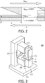
- Figure 2 illustrates the conflicting effects of the variables ⁇ min and w on the travel time T bead : Decreasing width w reduces the distance a magnetic particle has to travel, but reduces also the field gradient as ⁇ min increases.
- Figure 3 shows in a perspective view a concrete realization of a preparation apparatus 200 according to the present invention.
- the apparatus comprises an actuation magnet 210 with is a C-shaped yoke 213 that is mounted to a yoke holder on a base plate.
- a cuboid-shaped sample cartridge 2 is disposed in the sample space between a first, tapered pole 211 and a flat second pole 212.
- the gap between the poles typically has a width between a minimum of 4.5 mm and a maximum of 10 mm.
- the first pole 211 is exchangeable and has a single tip in one corner.
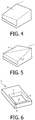
- FIG 4 shows a possible design of an exchangeable tip that can be used as a first pole 211 in the apparatus 200 of Figure 3 .
- the tip surface is constituted by just one facet F slanted in two directions such that it yields a single tip T in one corner.
- Figure 5 shows an alternative design of an exchangeable tip with a surface that is composed of two triangular facets F.
- Figure 6 shows a possible design of a sample cartridge 2 in which the sample fluid with magnetic particles can be provided.
- the sample cartridge 2 has the shape of a cuboid or box with a sample chamber 3 of square cross section that can be filled via two inlets 4.
- One corner of the sample chamber 3 provides a target area 5 at which magnetic particles can collect when a sample cartridge 2 is inserted into a preparation apparatus according to the invention.
- An outlet or a connection to other fluidic chambers is provided in this corner, too.
- the walls of the sample cartridge 2 are comparatively thick to ensure that the sample fluid has a sufficient distance from the borders of the magnetic poles, hence avoiding artifacts occurring there.
- the performance of the system with respect to changes of the parameters actuation current, particle concentration, pole tip geometry and bead type could be quantified.
- the results show that the enrichment of a typical sample consisting of an aqueous solution with 2.8 ⁇ m large magnetic beads at a concentration of 10 6 per ml could be enriched in less than 5 minutes at a power consumption of less than 5 W.
Landscapes
- Investigating Or Analyzing Materials By The Use Of Magnetic Means (AREA)
- Apparatus Associated With Microorganisms And Enzymes (AREA)
Description
- The invention relates to a method and a corresponding preparation apparatus for the enrichment of magnetic particles in a sample fluid.
- The
WO 2008/155716 discloses an optical biosensor in which an input light beam is totally internally reflected and the resulting output light beam is detected and evaluated with respect to the amount of target components at the reflection surface. The target components comprise magnetic particles as labels, which allows to affect the processes in the sample by magnetic forces. - The
WO 98/38293 A1 US 3 608 718 A . - The
US 7 474 184 B1 discloses a magnetic structure comprising two mirror-symmetric pole tips with concavities forming a space in which a sample can be manipulated. - The
US 4 238 323 A discloses the separation of nonmagnetic, electrically conductive particles by letting them flow through a region between two poles of a magnet such that eddy currents are induced in the particles. The poles may be tapered with their tips lying opposite to each other in a mirror-symmetric fashion. TheUS 3 645 377 A uses a similar approach to orient moved current-conducting bodies between the mirror-symmetric poles of a magnet. TheUS 1 317 992 A discloses a related device that uses the magnetic force between two wedge-shaped, mirror-symmetric poles for separating iron containing components from a batch employed in the manufacture of glass. A similar apparatus for the separation of particles with different electrical conductivities by moving them through a magnetic field between two poles is disclosed in theDE 20 37 088 A1 . In one embodiment, one of the poles is flat while the opposite pole has the shape of a truncated cone. - The
WO 97/26084 A1 - The
US 2007/056912 A1 discloses a magnetic separator with a cylindrical vessel through which a sample with magnetic particles can flow. Magnetic poles are arranged at diametrically opposite sides of the vessel in a mirror-symmetric fashion. The document mentions that the magnetic flux inside the vessel should be large enough to saturate the magnetism of the particles. - The
US 5 411 863 A discloses an apparatus in which superparamagnetic particles with a biologically active coating can be separated from the remainder of a sample. This is achieved by letting the sample with said particles flow through a chamber between the planar, parallel poles of a magnet. The magnetic field strength is adjusted such that the magnetic particles are magnetized to more than 90 % of their saturation magnetization. The particles are retained in the chamber, from which they can later be eluted. - The
GB 549 391 A - The
WO 2009/022994 A1 discloses a microfluidic separation system, which comprises a magnetic separator, which itself comprises a magnetic energy source; first and second magnetically conductive members leading from the magnetic energy source and having respective terminal ends that are separated by a gap over which a magnetic field is applied due to the magnetic energy source. The separation system further comprises a microfluidic chip for insertion into the gap, which comprises a body defining channels on respective faces of the body; and an exterior lining that seals the plurality of channels to allow separate test sample volumes to circulate in at least two of the channels. Upon insertion of the chip into the gap, a first test sample volume is confined to circulating closer to the terminal end of the first member and a second test sample volume is confined to circulating closer to the terminal end of the second member. - Based on this background it was an object of the present invention to provide means that allow to detect low concentrations of target substances with a biosensor.
- This object is achieved by a preparation apparatus according to
claim 1 and a method according toclaim 2. Preferred embodiments are disclosed in the dependent claims. - According to its first aspect, the invention relates to a preparation apparatus for the enrichment of magnetic particles in a sample fluid. In this context, the combination of a particular type of magnetic particles and a particular sample fluid shall be considered as being given and having predetermined characteristics, particularly in terms of magnetic properties of the magnetic particles and their migration velocity in the sample fluid under the influence of e.g. magnetic forces. The preparation apparatus has a design that is adapted to the given magnetic particles and sample fluid. It comprises an actuator magnet with a first and a second magnetic pole, wherein the following features shall be realized:
- a) Said poles of the actuator magnet are separated by a sample space into which a sample cartridge with the given sample fluid can be inserted. Treatment of the sample fluid can hence be done in the gap between the two poles, where the magnetic field concentrates.
- b) The first pole is tapered with a single (connected) tip region at which the distance of the second pole from the surface points of the first pole is locally minimal. A "local minimum" of the distance of an object X from a surface point means that said point has no neighboring points on the surface for which the distance to X is smaller (however, neighboring points may have the same distance and hence also belong to the tip region). As there shall only be a single local minimum of the distance (assumed in the tip region of the first pole), this distance is simultaneously also the global distance minimum between the poles.
- c) The actuator magnet is designed such that the magnetic flux in the sample space can (during operation of the apparatus) be made high enough to magnetize the given magnetic particles (when they are in the sample space) to at least about 50 %, preferably to about 90 % of their saturation magnetization (wherein "about" typically means ± 20 % of the respective value). The concrete value of the minimal magnetic flux which has to be provided throughout the sample space has to be derived from the properties of the given magnetic particles, which can readily be done based on available data sheets or simple measurements.
- d) Furthermore, the actuator magnet shall be designed such that there is a magnetic field gradient in the sample space (during operation of the apparatus) which can be made large enough to induce migration of the given magnetic particles (when they are in the sample space) with at least a given average migration velocity. The average migration velocity is a design parameter that has to be chosen in advance. The higher its value, the faster the enrichment of magnetic particles will be. In typical examples, the minimum average migration velocity ranges between about 1 µm/s and 1 mm/s. Based on the given value of the average migration velocity, the required magnetic field gradient in the sample space can readily be derived from data sheets or measurements with the given magnetic particles and sample fluid.
- The invention further relates to a corresponding method for the enrichment of magnetic particles in a sample fluid having given characteristics, said method comprising the following steps:
- a) Providing the sample fluid with the magnetic particles in a sample space.
- b) Establishing a magnetic flux in the sample space that is high enough to magnetize the given magnetic particles to at least about 50 %, preferably to about 90 % of their saturation magnetization.
- c) Establishing a magnetic field gradient in the sample space that is large enough to induce migration of the magnetic particles with at least a given average migration velocity, wherein said migration is directed towards a single tip region.
- The method comprises in general terms a procedure that can be executed with the preparation apparatus defined above. Consequently, the method is preferably executed with such an apparatus.
- The preparation apparatus and the method described above have the advantage that they allow the enrichment of magnetic particles in a sample fluid with high efficiency, as both the magnetic flux and the magnetic field gradient in the sample fluid are determined with respect to the properties of the particular magnetic particles and sample fluid under consideration. It is possible to use this apparatus and method to enrich magnetically labeled target components of a sample to a level at which they can readily and reliably be detected by a biosensor, or can be further manipulated and processed, e.g. in an integrated lab-on-a-chip device or cartridge. The detection limit of the biosensor can hence be extended while still providing a procedure that is suited for a simple and rapid (e.g. outdoor) application. Compactness makes the apparatus particularly apt for an integration with further components (e.g. a biosensor), yielding a favorable near-patient (point-of-care) setting.
- In the following, further developments of the invention will be described that relate to both the preparation apparatus and the method described above.
- Concrete values for the magnetic flux that shall be established in the sample space preferably range above about 50 mT. Most preferred is a value of about 100 mT. With these values, the desired degree of magnetization can be achieved for a large class of magnetic particles that are often used in practice (e.g. superparamagnetic beads having a diameter of typically between about 3 nm and 5 µm).
- A concrete value for the magnetic field gradient that shall be established during operation (everywhere) in the sample space is at least 0.2 T/m, preferably at least 0.6 T/m. These values prove to generate satisfactory migration velocities for a large class of practically important magnetic particles and a sample fluids. Typical average migration velocities that can be achieved by such gradient values range between about 10 µm/s and 300 µm/s.
- The sample space preferably has a volume of about 0.1 ml to about 10 ml, most preferably of about 1 ml. As many known biosensors process small sample volumes of some µl, an enrichment factor of about 1000 can be achieved when an initial sample volume of about one ml is reduced to the µl size required by the biosensor. The detection limit of the biosensor can hence be extended by several orders of magnitude.
- The maximal distance of the surface points of the first pole from the second pole preferably ranges between about 5 mm and about 20 mm. The concrete values will be chosen according to the applied electrical excitation, i.e. the power input at given coil dimensions. Hence a quite typical value is about 10 mm.
- The minimal distance of the surface points of the first pole from the second pole preferably ranges between about 2 mm and about 18 mm, preferably having a value of about 4.5 mm.
- Furthermore, at least one of the poles of the actuator magnet preferably covers an area between about 100 mm2 and about 600 mm2, preferably of about 300 mm2. In this context, the "area of a pole" is defined by the cross-section perpendicular to the mean direction of the magnetic field between the poles. Preferably, the respective areas of the two poles are substantially of the same size.
- The above mentioned specific values for the geometry of the poles prove to be suited for many typical boundary conditions occurring in practice.
- By definition, the "tip region" of the first pole is the (connected) area where the distance of surface points of the first pole to the second pole is locally minimal. For this reason, the tip region (or, more precisely, the sample space volume adjacent to the tip region) will be the target zone to which magnetic particles in the sample space migrate under the influence of the applied magnetic fields. Depending on the particular design of the poles, the tip region may be a two-dimensional area, an (approximately) one-dimensional line, or (approximately) a point. The latter embodiment has the advantage to provide the highest spatial concentration of magnetic particles during the enrichment procedure.
- In general, the surface of the first pole as well as the surface of the second pole may be arbitrarily shaped as long as the postulated features (e.g. the existence of a single tip region) are fulfilled. The surface shape of the tapered first pole can be optimized with respect to its intended effects, e.g. by implementing a parabolic shape that enables a stronger field gradient in the outer regions of the cartridge, which could accelerate the movement of single particles that are present in said region.
- In a preferred embodiment, the surface of the first pole is composed of one or more planar facets. Such facets can readily be manufactured. Moreover, in combination with a similarly simple (e.g. planar) surface of the second pole, the extremes of the magnetic field gradient can readily be estimated for such a design as occurring along the edges of the facets.
- According to another preferred embodiment of the invention, the actuator magnet comprises a yoke with two opposing ends that constitute the first and second pole with the intermediate sample space. As usual, a "yoke" denotes a (bended) bar of a material with high magnetic permeability that is used to concentrate magnetic field lines.
- According to a further development of the aforementioned embodiment, the yoke extends through at least one electromagnetic coil. Supplying this coil with electrical currents can hence be used to controllably generate a magnetic field which is guided by the yoke to the sample space between the poles.
- The aforementioned coil is preferably designed such that it has a number N ≥ 1 of windings which can be supplied with current I (in a stable operation mode, i.e. observing given current-density limits etc.), wherein the product N·I ranges between about 500 A and about 2000 A. It is feasible to design an actuator magnet for these values that is suited for the integration into a compact enrichment apparatus and that provides an appropriate magnetic field in the sample space.
- According to another embodiment, the yoke may comprise a permanent magnet for generating a magnetic field in the yoke and hence between the poles. The permanent magnet may be used alone or in combination with the aforementioned electromagnetic coil. The permanent magnet may optionally constitute an exchangeable component that can be inserted into the yoke if desired or that can be removed from the yoke (and e.g. be replaced by a neutral piece of yoke material).
- These and other aspects of the invention will be apparent from and elucidated with reference to the embodiment(s) described hereinafter. These embodiments will be described by way of example with the help of the accompanying drawings in which:
-
Figure 1 schematically shows a preparation apparatus according to a first embodiment of the invention; -
Figure 2 illustrates conflicting effects that the slope and width of a pole tip have on the travel time of magnetic beads; -
Figure 3 shows a perspective view of a concrete realization of a preparation apparatus; -
Figure 4 shows a pole for the apparatus ofFigure 3 with one facet; -
Figure 5 shows a pole for the apparatus ofFigure 3 with two facets; -
Figure 6 shows an exemplary sample cartridge. - Like reference numbers or numbers differing by integer multiples of 100 refer in the Figures to identical or similar components.
- The detection of nucleic acids in a biological fluid requires a series of processing steps, such as sample enrichment, cell lysis, DNA isolation and amplification. Since the target analyte is often only available in trace amounts, large sample volumes are needed to collect a statistically sufficient amount of molecules. In such an environment, the detection is hampered by the background noise originating from other constituents of the sample, such as blood cells or cell debris. Hence, it is desirable to extract the available target molecules and to introduce them into a smaller volume, thus effectively enhancing their concentration. As a result, the requirements imposed by the detection limit of the subsequent sensing processes can be met.
- Moreover, the processable sample volume of a biosensor is ideally not larger than several microliters such that the typical characteristics of a microfluidic device, e.g. low consumption of reagents and rapid reaction kinetics, can be realized. However, lowly concentrated samples of this size might not contain enough target molecules to enable reliable detection results.
- In a biosensor based on magnetic particles (beads), the target molecules (e.g. nucleic acids) may be caught from an initial volume by specific or non-specific attachment to the surface of said beads. In an enrichment step, an external magnetic field may then be used to collect the particles from the initial volume and transfer them to a confined region, thereby increasing their local concentration and preparing them for further processing.
- In such a biosensor based on magnetic beads, the technological challenge arises from the typically large initial volume of the sample to be purified, which is here assumed to be at least 1 ml. Previous technological solutions towards the directed movement of magnetic beads commonly handle considerably smaller fluid volumes and cannot be easily adapted to the desirable sample size because the range of the generated magnetic forces is insufficient (cf. A. Rida, V. Fernandez, and M. A. M. Gijs, "Long-range transport of magnetic microbeads using simple planar coils placed in a uniform magnetostatic field", Applied Physics Letters, vol. 83, no. 12, pp.2396-2398, 2003; J. Joung, J. Shen, and P. Grodzinski,"Micropumps based on alternating high-gradient magnetic fields", IEEE Transactions on Magnetics, vol. 40, no. 4, pp. 1944-1946, 2004). Other known designs for the purification of sample volumes by using magnetic beads feature numerous moving parts and are therefore not robust enough for hand-held solutions (
EP 1 621 890 A1 - For the above reasons, efficient sample purification is considered a vital feature of future biosensor applications. It is therefore desirable to develop a magnetic actuator that fulfils as many as possible of the following requirements:
- It can concentrate suspended magnetic beads from a milliliter volume into a microliter volume.
- It works power-efficiently enough to allow for off-the-grid operation.
- It finishes the enrichment process in less than about 5 minutes.
- It is compatible with ensuing process steps.
- It ideally works without mechanically moving parts.
- To meet the above requirements, a preparation apparatus is proposed here in which the actuation unit consists of a magnetic circuit comprising an air gap and at least one magnetic field generator, e.g. a field coil. At least one of the pole tips of the apparatus has a tapered shape such that a region of least distance exists between the pole tips. During operation of the apparatus, the magnetic flux density between the pole tips exhibits a maximum at the position of least distance. If a fluid sample containing magnetic beads in suspension is introduced into the air gap, the gradient of the magnetic field will elicit the migration of particles towards the maximum of the magnetic field.
-
Figure 1 shows schematically in a side view apreparation apparatus 100 according to an embodiment of the above principles. As a main component, thepreparation apparatus 100 comprises anactuator magnet 110, which is realized (inter alia) by a C-shapedyoke 113 having afirst pole 111 and asecond pole 112 that are disposed opposite to each other with an intermediate air gap orsample space 115 between them. Two branches of theyoke 113 are surrounded bycoils 121 that can be supplied with an electrical current to generate a magnetic field in the yoke and correspondingly in thesample space 115. Furthermore, apermanent magnet 122 may optionally be integrated into the yoke, preferably such that it may be replaced by a piece of "normal" yoke material if desired. - While the
second pole 112 has a flat surface that is perpendicular to the yoke axis in this branch (z-direction), thefirst pole 111 is tapered (wedge shaped) with a single tip T at one end. The distance between points on the surface of thefirst pole 111 and thesecond pole 112 hence decreases from a maximum value δmax to a minimal value δmin, which is assumed at the tip T (it should be noted that this distance is defined asymmetrically, i.e. considering single points on the surface of the first pole in relation to the whole second pole). The width of the first andsecond poles first pole 111 can be calculated by
- Analysis shows that this angle α of slope is directly proportional to the achievable force on a particle between the poles.
-
Figure 1 further shows that asample cartridge 2 comprising a sample liquid withmagnetic particles 1 is inserted into thesample space 115 between the poles of theactuator magnet 110. Thesample cartridge 2 has the shape of a cuboid with the volume
- During operation of the
preparation apparatus 100, themagnetic particles 1 are moved by the magnetic field gradient towards the point T of least distance between thepoles WO 2008/155716 ), it has to be possible to readily remove beads from thesample cartridge 2. As shown in the Figure, it is therefore favorable to place the collection area at the outer border of thesample cartridge 2. - The shape of the
poles - The electrical excitation N·I of the magnetic circuit is fixed (with N being the number of windings of the
coils 121 and I the current applied to the coils). The concrete value of N·I may be determined based on constraints with respect to a practical size of the coils and the maximum current that can permanently be applied. - The magnetic flux density in every point of the
sample space 115 between the poles shall at least be Bmin = 100 mT. This value is motivated by the postulation that the used magnetic beads should be magnetized to about 90 % of their saturation magnetization, because migration velocity of the beads is proportional to their magnetization. The concrete value of Bmin can be found from corresponding data sheets of the beads. - The maximum width δmax of the
sample space 115 is then fixed to a value that guarantees the magnetic flux density Bmin at the given electrical excitation N·I. - Under these premises, the values for δmin and w may be varied under the condition that the available volume V for the box-shaped
cartridge 2 remains constant, and that the total travel time Tbead a bead needs for the transversal migration through the whole sample space (i.e. across distance w) is minimal.Figure 2 illustrates the conflicting effects of the variables δmin and w on the travel time Tbead: Decreasing width w reduces the distance a magnetic particle has to travel, but reduces also the field gradient as δmin increases. The optimal combination of w and δmin, which minimizes the travel time Tbead, can be found by theoretical analysis or experiments. For an electrical excitation of N·I = 800 A and a volume of V = 1 ml, the following parameters can thus be determined: - minimum air gap δmin = 4.5 mm,
- maximum air gap δmax = 10 mm,
- width of poles w = 17 mm.
- While a box-shaped,
cuboid cartridge 2 has been assumed for the optimization, the implementation of a specifically shaped cartridge that exactly fits into thesample space 115 will allow for larger sample volumes V. The determined optimum values are expected to be approximately invariant to such a change of the shape of the cartridge. -
Figure 3 shows in a perspective view a concrete realization of apreparation apparatus 200 according to the present invention. As inFigure 1 , the apparatus comprises anactuation magnet 210 with is a C-shapedyoke 213 that is mounted to a yoke holder on a base plate. Theyoke 213 comprises an exchangeable yoke element, for example apermanent magnet 222, and two copper coils 221 (with typically N = 700 windings and a wire diameter of 0.5 mm). A cuboid-shapedsample cartridge 2 is disposed in the sample space between a first, taperedpole 211 and a flatsecond pole 212. The gap between the poles typically has a width between a minimum of 4.5 mm and a maximum of 10 mm. Thefirst pole 211 is exchangeable and has a single tip in one corner. -
Figure 4 shows a possible design of an exchangeable tip that can be used as afirst pole 211 in theapparatus 200 ofFigure 3 . The tip surface is constituted by just one facet F slanted in two directions such that it yields a single tip T in one corner. -
Figure 5 shows an alternative design of an exchangeable tip with a surface that is composed of two triangular facets F. -
Figure 6 shows a possible design of asample cartridge 2 in which the sample fluid with magnetic particles can be provided. Thesample cartridge 2 has the shape of a cuboid or box with asample chamber 3 of square cross section that can be filled via twoinlets 4. One corner of thesample chamber 3 provides atarget area 5 at which magnetic particles can collect when asample cartridge 2 is inserted into a preparation apparatus according to the invention. An outlet or a connection to other fluidic chambers is provided in this corner, too. It should be noted that the walls of thesample cartridge 2 are comparatively thick to ensure that the sample fluid has a sufficient distance from the borders of the magnetic poles, hence avoiding artifacts occurring there. - By assigning a time constant to the enrichment process, the performance of the system with respect to changes of the parameters actuation current, particle concentration, pole tip geometry and bead type could be quantified. The results show that the enrichment of a typical sample consisting of an aqueous solution with 2.8 µm large magnetic beads at a concentration of 106 per ml could be enriched in less than 5 minutes at a power consumption of less than 5 W.
- While the invention was described above with reference to particular embodiments, various modifications and extensions are possible, for example:
- The poles of the actuation magnet may have other forms than the shown ones, for example they may both tapered.
- The sensor that is applied to the enriched sample can be any suitable sensor to detect the presence of magnetic particles on or near to a sensor surface, based on any property of the particles, e.g. it can detect via magnetic methods, optical methods (e.g. imaging, fluorescence, chemiluminescence, absorption, scattering, evanescent field techniques, surface plasmon resonance, Raman, etc.), sonic detection (e.g. surface acoustic wave, bulk acoustic wave, cantilever, quartz crystal etc), electrical detection (e.g. conduction, impedance, amperometric, redox cycling), combinations thereof, etc. A magnetic sensor can be any suitable sensor based on the detection of the magnetic properties of the particle on or near to a sensor surface, e.g. a coil, magneto-resistive sensor, magneto-restrictive sensor, Hall sensor, planar Hall sensor, flux gate sensor, SQUID, magnetic resonance sensor, etc.
- In addition to molecular assays, also larger moieties can be processed and detected with devices according to the invention, e.g. cells, viruses, or fractions of cells or viruses, tissue extract, etc.
- The particles serving as labels can be detected directly by the sensing method. As well, the particles and/or the biological targets on their surface can be further processed prior to detection. An example of further processing is that materials are added or released, or that the (bio)chemical or physical properties of the label and/or the biological targets are modified to facilitate detection. The particles and/or biological targets can be further manipulated and processed, e.g. in an integrated lab-on-a-chip device or in a disposable cartridge.
- The device and method can be used in combination with rapid, robust, and easy to use point-of-care biosensors for small sample volumes. The sample cartridge can be a disposable item. Also, the device, methods and systems of the present invention can be used in automated high-throughput testing.
- The magnetic particles or beads typically have at least one dimension ranging between 3 nm and 5000 nm, preferably between 500 nm and 5000 nm, more preferred between 1000 nm and 5000 nm. Experiments with 2.8 µm beads showed the best performance in comparison with 1 µm and 500 nm beads. Larger beads are expected to lead to even better results.
- Finally it is pointed out that in the present application the term "comprising" does not exclude other elements or steps, that "a" or "an" does not exclude a plurality, and that a single processor or other unit may fulfill the functions of several means. The invention is defined only by the appended claims. Moreover, reference signs in the claims shall not be construed as limiting their scope.
Claims (15)
- A preparation apparatus (100, 200) for the enrichment of magnetic particles (1) in a sample fluid having given characteristics, the apparatus comprising a sample cartridge (2) in which the sample with the magnetic particles is provided, and an actuator magnet (110, 210) with a first and a second pole (111, 112, 211, 212), wherein:a) said poles are separated by a sample space (115) into which the sample cartridge (2) with the sample fluid can be inserted;b) first pole (111, 211) is tapered with a single tip region (T) at which a distance (δmin) of the second pole (112, 212) from surface points of the first pole is locally minimal;c) magnetic flux in the sample space (115) can be made high enough to magnetize the magnetic particles (1) to at least 50 % of their saturation magnetization;d) magnetic field gradient in the sample space (115) can be made large enough to induce migration of the magnetic particles (1) in the sample space (115) towards the tip region (T) with a given minimum average velocity.
- A method for the enrichment of magnetic particles (1) in a sample fluid having given characteristics, comprising the following steps:a) providing the sample fluid with the magnetic particles in a sample space (115) separating a first and second magnetic poles whose the first one is tapered with a single tip region at which a distance (δmin) of the second pole (112, 212) from surface points of the first pole is locally minimal;b) establishing a magnetic flux in the sample space (115) that is high enough to magnetize the magnetic particles (1) to at least 50 % of their saturation magnetization;c) establishing a magnetic field gradient in the sample space (115) that is large enough to induce migration of the magnetic particles (1) in the sample space (115) with a given minimum average velocity towards a single tip region (T).
- The method according to claim 2,
characterized in that it is executed with a preparation apparatus (100, 200) according to claim 1. - The apparatus (100, 200) according to claim 1 or the method according to claim 2,
characterized in that the magnetic flux in the sample space (115) is at least 50 mT, preferably at least 100 mT. - The apparatus (100, 200) according to claim 1 or the method according to claim 2,
characterized in that the magnetic field gradient in the sample space (115) is at least 0.2 T/m, preferably at least 0.6 T/m. - The apparatus (100, 200) according to claim 1 or the method according to claim 2,
characterized in that the sample space (115) has a volume of 0.1 ml to 10 ml. - The apparatus (100, 200) according to claim 1 or the method according to claim 3,
characterized in that the maximal distance (δmax) of the surface points of the first pole (111, 211) from the second pole (112, 212) ranges between 5 mm and 20 mm. - The apparatus (100, 200) according to claim 1 or the method according to claim 3,
characterized in that the minimal distance (δmin) of the second pole (112, 212) from the first pole (111, 211) ranges between 2 mm and 18 mm. - The apparatus (100, 200) according to claim 1 or the method according to claim 3,
characterized in that at least one of the poles (111, 112, 211, 212) has an area between 100 mm2 and 600 mm2, wherein said area is defined by the cross-section perpendicular to the mean direction of the magnetic field between the poles (111, 112, 211, 212). - The apparatus (100, 200) according to claim 1 or the method according to claim 2,
characterized in that the tip region (T) is approximately a point. - The apparatus (100, 200) according to claim 1 or the method according to claim 3,
characterized in that the surface of the first pole (111, 211) is composed of planar facets (F). - The apparatus (100, 200) according to claim 1 or the method according to claim 3,
characterized in that the actuator magnet (110, 210) comprises a yoke (113, 213) with two opposing ends that constitute the first and second pole (111, 112, 211, 212). - The apparatus (100, 200) or the method according to claim 12,
characterized in that the yoke (113, 213) extends through at least one coil (121, 221). - The apparatus (100, 200) or the method according to claim 13,
characterized in that the coil (121, 221) has N windings and can be driven with a current I, wherein N·I ranges between 500 A and 2000 A. - The apparatus (100, 200) or the method according to claim 12,
characterized in that the yoke (113, 213) comprises a permanent magnet (122, 222).
Priority Applications (1)
| Application Number | Priority Date | Filing Date | Title |
|---|---|---|---|
| EP10740362.8A EP2454020B1 (en) | 2009-07-17 | 2010-07-12 | Apparatus and method for the enrichment of magnetic particles |
Applications Claiming Priority (3)
| Application Number | Priority Date | Filing Date | Title |
|---|---|---|---|
| EP09165750 | 2009-07-17 | ||
| PCT/IB2010/053176 WO2011007310A1 (en) | 2009-07-17 | 2010-07-12 | Apparatus for the enrichment of magnetic particles |
| EP10740362.8A EP2454020B1 (en) | 2009-07-17 | 2010-07-12 | Apparatus and method for the enrichment of magnetic particles |
Publications (2)
| Publication Number | Publication Date |
|---|---|
| EP2454020A1 EP2454020A1 (en) | 2012-05-23 |
| EP2454020B1 true EP2454020B1 (en) | 2019-05-15 |
Family
ID=42697202
Family Applications (1)
| Application Number | Title | Priority Date | Filing Date |
|---|---|---|---|
| EP10740362.8A Not-in-force EP2454020B1 (en) | 2009-07-17 | 2010-07-12 | Apparatus and method for the enrichment of magnetic particles |
Country Status (4)
| Country | Link |
|---|---|
| US (1) | US9272290B2 (en) |
| EP (1) | EP2454020B1 (en) |
| CN (1) | CN102470373B (en) |
| WO (1) | WO2011007310A1 (en) |
Families Citing this family (10)
| Publication number | Priority date | Publication date | Assignee | Title |
|---|---|---|---|---|
| US9018942B2 (en) * | 2013-01-11 | 2015-04-28 | Bourns, Inc. | Position measurement using a variable flux collector |
| US20140248679A1 (en) * | 2013-03-02 | 2014-09-04 | Jing Zhang | Apparatus and Methods to Enhance Field Gradient For Magnetic Rare Cell Separation |
| US10444304B2 (en) * | 2014-03-26 | 2019-10-15 | General Electric Company | Particle event recordation |
| EP3161485B1 (en) | 2014-06-25 | 2018-10-31 | Koninklijke Philips N.V. | Biosensor for the detection of target components in a sample |
| US20190078981A1 (en) * | 2016-03-17 | 2019-03-14 | Sk Telecom Co., Ltd. | Bio sample pre-treatment device |
| KR101888636B1 (en) * | 2017-06-02 | 2018-08-14 | 지트로닉스 주식회사 | Magnetophoresis biochip |
| CN114011479B (en) | 2017-06-06 | 2023-05-02 | 西北大学 | Cross-interface magnetic separation |
| CN107845477A (en) * | 2017-11-24 | 2018-03-27 | 西安交通大学 | A kind of controlling magnetic field generator screened for magnetic bionanoparticles particle diameter with being homogenized |
| DE102022200663A1 (en) | 2022-01-21 | 2023-07-27 | Robert Bosch Gesellschaft mit beschränkter Haftung | Microfluidic device and method of its operation |
| CN117050876A (en) * | 2023-08-15 | 2023-11-14 | 南通大学附属医院 | Gradient magnetic field device and application for magnetized cell targeted transplantation |
Citations (5)
| Publication number | Priority date | Publication date | Assignee | Title |
|---|---|---|---|---|
| US7232691B2 (en) * | 2001-11-27 | 2007-06-19 | Los Alamos National Security, Llc | Bioassay and biomolecular identification, sorting, and collection methods using magnetic microspheres |
| US20070175830A1 (en) * | 2003-07-10 | 2007-08-02 | Brassard Lothar A | Device and method for separating magnetic or magnetizable particles from a liquid |
| WO2009022994A1 (en) * | 2007-08-13 | 2009-02-19 | Agency For Science, Technology And Research | Microfluidic separation system |
| US20090078614A1 (en) * | 2007-04-19 | 2009-03-26 | Mathew Varghese | Method and apparatus for separating particles, cells, molecules and particulates |
| WO2010031679A1 (en) * | 2008-09-18 | 2010-03-25 | Siemens Aktiengesellschaft | Separating device for separating particles able to be magnetized and particles not able to be magnetized transported in a suspension flowing through a separating channel |
Family Cites Families (31)
| Publication number | Priority date | Publication date | Assignee | Title |
|---|---|---|---|---|
| US1317992A (en) | 1919-10-07 | Magnetic separator | ||
| CH221010A (en) | 1940-09-10 | 1942-05-15 | Magnetos Lucifer S A | Process for the magnetic purification of a fluid and device for carrying out the process. |
| US3608718A (en) * | 1968-12-20 | 1971-09-28 | Bethlehem Steel Corp | Magnetic separator method and apparatus |
| US3645377A (en) | 1968-12-25 | 1972-02-29 | Igor Mikhailovich Kirko | Method of orientation of nonmagnetic current-conducting bodies magnetic field and devices for carrying same into effect |
| DE2037088A1 (en) | 1969-08-05 | 1971-02-18 | Univ Vanderbilt | Process and arrangement for separating particles with different electrical conductivities |
| US4238323A (en) * | 1979-02-02 | 1980-12-09 | Ioffe Benyamin A | Method of and apparatus for electrodynamic separation of nonmagnetic free-flowing materials |
| DK111582A (en) * | 1982-03-12 | 1983-09-13 | Niro Atomizer As | HIGH GRADUATE MAGNETIC SEPARATOR |
| US4961841A (en) * | 1982-05-21 | 1990-10-09 | Mag-Sep Corporation | Apparatus and method employing magnetic fluids for separating particles |
| US4784767A (en) * | 1986-03-20 | 1988-11-15 | Director General, Agency Of Industrial Science And Technology | Magnetic separator for fluids |
| ES2067018T3 (en) * | 1988-12-28 | 1995-03-16 | Stefan Miltenyi | PROCEDURE AND MATERIALS FOR THE SEPARATION IN HIGH MAGNETIC GRADIENT OF BIOLOGICAL MATERIALS. |
| US5200084A (en) * | 1990-09-26 | 1993-04-06 | Immunicon Corporation | Apparatus and methods for magnetic separation |
| US5466574A (en) * | 1991-03-25 | 1995-11-14 | Immunivest Corporation | Apparatus and methods for magnetic separation featuring external magnetic means |
| US20030127396A1 (en) * | 1995-02-21 | 2003-07-10 | Siddiqi Iqbal Waheed | Apparatus and method for processing magnetic particles |
| US5823354A (en) * | 1996-01-16 | 1998-10-20 | Rustec, Inc. | Method and apparatus for the separation and sorting of non-ferrous materials |
| JP3996644B2 (en) * | 1996-06-07 | 2007-10-24 | イムニベスト・コーポレイション | Magnetic separation with external and internal gradients |
| US5968820A (en) * | 1997-02-26 | 1999-10-19 | The Cleveland Clinic Foundation | Method for magnetically separating cells into fractionated flow streams |
| IT1313206B1 (en) * | 1998-07-14 | 2002-06-17 | Toushin Keisoku Corp | MAGNETIC TREATMENT EQUIPMENT FOR FLUIDS AND PROCEDURE FOR ITS USE. |
| US6361749B1 (en) * | 1998-08-18 | 2002-03-26 | Immunivest Corporation | Apparatus and methods for magnetic separation |
| DE10117659C2 (en) * | 2001-04-09 | 2003-07-17 | Steinert Gmbh Elektromagnetbau | High gradient magnetic filter and method for separating weakly magnetizable particles from liquid media |
| US6939032B2 (en) * | 2001-10-25 | 2005-09-06 | Erie Scientific Company | Cover slip mixing apparatus |
| AU2002366904A1 (en) | 2001-12-21 | 2003-07-09 | Koninklijke Philips Electronics N.V. | Sensor and method for measuring the areal density of magnetic nanoparticles on a micro-array |
| CN1230531C (en) * | 2002-12-09 | 2005-12-07 | 清华大学 | Method and kit for separating cell particle from sample |
| US20050148064A1 (en) * | 2003-12-29 | 2005-07-07 | Intel Corporation | Microfluid molecular-flow fractionator and bioreactor with integrated active/passive diffusion barrier |
| EP1621890A1 (en) | 2004-07-26 | 2006-02-01 | bioMerieux B.V. | Device and method for separating, mixing and concentrating magnetic particles with a fluid and use thereof in purification methods |
| US7658854B2 (en) | 2004-10-08 | 2010-02-09 | Exportech Company, Inc. | Apparatus and method for continuous separation of magnetic particles from non-magnetic fluids |
| US7474184B1 (en) | 2005-02-15 | 2009-01-06 | The Regents Of The University Of California | Hybrid magnet devices for molecule manipulation and small scale high gradient-field applications |
| JP2009536346A (en) | 2006-05-09 | 2009-10-08 | コーニンクレッカ フィリップス エレクトロニクス エヌ ヴィ | Magnetic sensor device having a magnetic field generator and a sensor |
| JP2009536352A (en) | 2006-05-10 | 2009-10-08 | コーニンクレッカ フィリップス エレクトロニクス エヌ ヴィ | System and method for operation in a magnetoresistive sensor |
| EP2082231A2 (en) | 2006-10-09 | 2009-07-29 | Koninklijke Philips Electronics N.V. | Magnetic sensor device with pairs of detection units |
| JP5236660B2 (en) * | 2006-12-20 | 2013-07-17 | コーニンクレッカ フィリップス エレクトロニクス エヌ ヴィ | Method and apparatus for separating magnetic particles, magnetic particles, and use of magnetic particles |
| EP2181322A1 (en) | 2007-06-21 | 2010-05-05 | Koninklijke Philips Electronics N.V. | Microelectronic sensor device for detecting label particles |
-
2010
- 2010-07-12 US US13/384,251 patent/US9272290B2/en active Active
- 2010-07-12 CN CN201080032239.7A patent/CN102470373B/en not_active Expired - Fee Related
- 2010-07-12 EP EP10740362.8A patent/EP2454020B1/en not_active Not-in-force
- 2010-07-12 WO PCT/IB2010/053176 patent/WO2011007310A1/en not_active Ceased
Patent Citations (5)
| Publication number | Priority date | Publication date | Assignee | Title |
|---|---|---|---|---|
| US7232691B2 (en) * | 2001-11-27 | 2007-06-19 | Los Alamos National Security, Llc | Bioassay and biomolecular identification, sorting, and collection methods using magnetic microspheres |
| US20070175830A1 (en) * | 2003-07-10 | 2007-08-02 | Brassard Lothar A | Device and method for separating magnetic or magnetizable particles from a liquid |
| US20090078614A1 (en) * | 2007-04-19 | 2009-03-26 | Mathew Varghese | Method and apparatus for separating particles, cells, molecules and particulates |
| WO2009022994A1 (en) * | 2007-08-13 | 2009-02-19 | Agency For Science, Technology And Research | Microfluidic separation system |
| WO2010031679A1 (en) * | 2008-09-18 | 2010-03-25 | Siemens Aktiengesellschaft | Separating device for separating particles able to be magnetized and particles not able to be magnetized transported in a suspension flowing through a separating channel |
Also Published As
| Publication number | Publication date |
|---|---|
| CN102470373B (en) | 2014-11-26 |
| US9272290B2 (en) | 2016-03-01 |
| EP2454020A1 (en) | 2012-05-23 |
| CN102470373A (en) | 2012-05-23 |
| WO2011007310A1 (en) | 2011-01-20 |
| US20120161754A1 (en) | 2012-06-28 |
Similar Documents
| Publication | Publication Date | Title |
|---|---|---|
| US9272290B2 (en) | Apparatus for the enrichment of magnetic particles | |
| Suwa et al. | Magnetoanalysis of micro/nanoparticles: A review | |
| Gijs et al. | Microfluidic applications of magnetic particles for biological analysis and catalysis | |
| RU2415433C2 (en) | Fast and sensitive measurement of biodata | |
| CA2654841C (en) | A method for manipulating magnetic particles in a liquid medium | |
| CN103501912B (en) | Apparatus and method for separating magnetic mark part in sample | |
| US9421555B2 (en) | Non-linear magnetophoretic separation device, system and method | |
| US20090053799A1 (en) | Trapping magnetic sorting system for target species | |
| US8999732B2 (en) | Method for manipulating magnetic particles in a liquid medium | |
| US20110127222A1 (en) | Trapping magnetic cell sorting system | |
| EP3059583B1 (en) | An electromagnetic system for biosensors | |
| US20090206832A1 (en) | Magnetic sensor device | |
| WO2013041983A1 (en) | Microfluidic system | |
| JP2009544033A (en) | Attraction and separation of magnetic or magnetizable objects from the sensor surface | |
| EP1974821A1 (en) | Method and apparatus for transporting magnetic or magnetisable microbeads | |
| EP1982768A2 (en) | Methods for pathogen detection | |
| US8486718B2 (en) | Magnetic system | |
| CN101553730B (en) | A magnetic system | |
| Afshar et al. | Magnetic particle dosing and size separation in a microfluidic channel | |
| ITTO20120302A1 (en) | INTEGRATED DEVICE AND METHOD FOR CHAIN REACTION OF REAL-TIME QUANTITATIVE POLYMERASIS | |
| Danckwardt et al. | Pump-free transport of magnetic particles in microfluidic channels |
Legal Events
| Date | Code | Title | Description |
|---|---|---|---|
| PUAI | Public reference made under article 153(3) epc to a published international application that has entered the european phase |
Free format text: ORIGINAL CODE: 0009012 |
|
| 17P | Request for examination filed |
Effective date: 20120217 |
|
| AK | Designated contracting states |
Kind code of ref document: A1 Designated state(s): AL AT BE BG CH CY CZ DE DK EE ES FI FR GB GR HR HU IE IS IT LI LT LU LV MC MK MT NL NO PL PT RO SE SI SK SM TR |
|
| DAX | Request for extension of the european patent (deleted) | ||
| RAP1 | Party data changed (applicant data changed or rights of an application transferred) |
Owner name: KONINKLIJKE PHILIPS N.V. |
|
| 17Q | First examination report despatched |
Effective date: 20140224 |
|
| GRAP | Despatch of communication of intention to grant a patent |
Free format text: ORIGINAL CODE: EPIDOSNIGR1 |
|
| STAA | Information on the status of an ep patent application or granted ep patent |
Free format text: STATUS: GRANT OF PATENT IS INTENDED |
|
| RIC1 | Information provided on ipc code assigned before grant |
Ipc: B03C 1/033 20060101ALI20181128BHEP Ipc: B03C 1/035 20060101AFI20181128BHEP |
|
| INTG | Intention to grant announced |
Effective date: 20181213 |
|
| GRAS | Grant fee paid |
Free format text: ORIGINAL CODE: EPIDOSNIGR3 |
|
| GRAA | (expected) grant |
Free format text: ORIGINAL CODE: 0009210 |
|
| STAA | Information on the status of an ep patent application or granted ep patent |
Free format text: STATUS: THE PATENT HAS BEEN GRANTED |
|
| AK | Designated contracting states |
Kind code of ref document: B1 Designated state(s): AL AT BE BG CH CY CZ DE DK EE ES FI FR GB GR HR HU IE IS IT LI LT LU LV MC MK MT NL NO PL PT RO SE SI SK SM TR |
|
| REG | Reference to a national code |
Ref country code: CH Ref legal event code: EP Ref country code: GB Ref legal event code: FG4D |
|
| REG | Reference to a national code |
Ref country code: DE Ref legal event code: R096 Ref document number: 602010058901 Country of ref document: DE |
|
| REG | Reference to a national code |
Ref country code: IE Ref legal event code: FG4D |
|
| REG | Reference to a national code |
Ref country code: NL Ref legal event code: MP Effective date: 20190515 |
|
| REG | Reference to a national code |
Ref country code: LT Ref legal event code: MG4D |
|
| PG25 | Lapsed in a contracting state [announced via postgrant information from national office to epo] |
Ref country code: AL Free format text: LAPSE BECAUSE OF FAILURE TO SUBMIT A TRANSLATION OF THE DESCRIPTION OR TO PAY THE FEE WITHIN THE PRESCRIBED TIME-LIMIT Effective date: 20190515 Ref country code: PT Free format text: LAPSE BECAUSE OF FAILURE TO SUBMIT A TRANSLATION OF THE DESCRIPTION OR TO PAY THE FEE WITHIN THE PRESCRIBED TIME-LIMIT Effective date: 20190915 Ref country code: ES Free format text: LAPSE BECAUSE OF FAILURE TO SUBMIT A TRANSLATION OF THE DESCRIPTION OR TO PAY THE FEE WITHIN THE PRESCRIBED TIME-LIMIT Effective date: 20190515 Ref country code: SE Free format text: LAPSE BECAUSE OF FAILURE TO SUBMIT A TRANSLATION OF THE DESCRIPTION OR TO PAY THE FEE WITHIN THE PRESCRIBED TIME-LIMIT Effective date: 20190515 Ref country code: HR Free format text: LAPSE BECAUSE OF FAILURE TO SUBMIT A TRANSLATION OF THE DESCRIPTION OR TO PAY THE FEE WITHIN THE PRESCRIBED TIME-LIMIT Effective date: 20190515 Ref country code: NO Free format text: LAPSE BECAUSE OF FAILURE TO SUBMIT A TRANSLATION OF THE DESCRIPTION OR TO PAY THE FEE WITHIN THE PRESCRIBED TIME-LIMIT Effective date: 20190815 Ref country code: FI Free format text: LAPSE BECAUSE OF FAILURE TO SUBMIT A TRANSLATION OF THE DESCRIPTION OR TO PAY THE FEE WITHIN THE PRESCRIBED TIME-LIMIT Effective date: 20190515 Ref country code: LT Free format text: LAPSE BECAUSE OF FAILURE TO SUBMIT A TRANSLATION OF THE DESCRIPTION OR TO PAY THE FEE WITHIN THE PRESCRIBED TIME-LIMIT Effective date: 20190515 Ref country code: NL Free format text: LAPSE BECAUSE OF FAILURE TO SUBMIT A TRANSLATION OF THE DESCRIPTION OR TO PAY THE FEE WITHIN THE PRESCRIBED TIME-LIMIT Effective date: 20190515 |
|
| PG25 | Lapsed in a contracting state [announced via postgrant information from national office to epo] |
Ref country code: LV Free format text: LAPSE BECAUSE OF FAILURE TO SUBMIT A TRANSLATION OF THE DESCRIPTION OR TO PAY THE FEE WITHIN THE PRESCRIBED TIME-LIMIT Effective date: 20190515 Ref country code: BG Free format text: LAPSE BECAUSE OF FAILURE TO SUBMIT A TRANSLATION OF THE DESCRIPTION OR TO PAY THE FEE WITHIN THE PRESCRIBED TIME-LIMIT Effective date: 20190815 Ref country code: GR Free format text: LAPSE BECAUSE OF FAILURE TO SUBMIT A TRANSLATION OF THE DESCRIPTION OR TO PAY THE FEE WITHIN THE PRESCRIBED TIME-LIMIT Effective date: 20190816 |
|
| REG | Reference to a national code |
Ref country code: AT Ref legal event code: MK05 Ref document number: 1132819 Country of ref document: AT Kind code of ref document: T Effective date: 20190515 |
|
| PG25 | Lapsed in a contracting state [announced via postgrant information from national office to epo] |
Ref country code: DK Free format text: LAPSE BECAUSE OF FAILURE TO SUBMIT A TRANSLATION OF THE DESCRIPTION OR TO PAY THE FEE WITHIN THE PRESCRIBED TIME-LIMIT Effective date: 20190515 Ref country code: SK Free format text: LAPSE BECAUSE OF FAILURE TO SUBMIT A TRANSLATION OF THE DESCRIPTION OR TO PAY THE FEE WITHIN THE PRESCRIBED TIME-LIMIT Effective date: 20190515 Ref country code: EE Free format text: LAPSE BECAUSE OF FAILURE TO SUBMIT A TRANSLATION OF THE DESCRIPTION OR TO PAY THE FEE WITHIN THE PRESCRIBED TIME-LIMIT Effective date: 20190515 Ref country code: CZ Free format text: LAPSE BECAUSE OF FAILURE TO SUBMIT A TRANSLATION OF THE DESCRIPTION OR TO PAY THE FEE WITHIN THE PRESCRIBED TIME-LIMIT Effective date: 20190515 Ref country code: AT Free format text: LAPSE BECAUSE OF FAILURE TO SUBMIT A TRANSLATION OF THE DESCRIPTION OR TO PAY THE FEE WITHIN THE PRESCRIBED TIME-LIMIT Effective date: 20190515 Ref country code: RO Free format text: LAPSE BECAUSE OF FAILURE TO SUBMIT A TRANSLATION OF THE DESCRIPTION OR TO PAY THE FEE WITHIN THE PRESCRIBED TIME-LIMIT Effective date: 20190515 |
|
| REG | Reference to a national code |
Ref country code: DE Ref legal event code: R097 Ref document number: 602010058901 Country of ref document: DE |
|
| PG25 | Lapsed in a contracting state [announced via postgrant information from national office to epo] |
Ref country code: MC Free format text: LAPSE BECAUSE OF FAILURE TO SUBMIT A TRANSLATION OF THE DESCRIPTION OR TO PAY THE FEE WITHIN THE PRESCRIBED TIME-LIMIT Effective date: 20190515 Ref country code: SM Free format text: LAPSE BECAUSE OF FAILURE TO SUBMIT A TRANSLATION OF THE DESCRIPTION OR TO PAY THE FEE WITHIN THE PRESCRIBED TIME-LIMIT Effective date: 20190515 Ref country code: IT Free format text: LAPSE BECAUSE OF FAILURE TO SUBMIT A TRANSLATION OF THE DESCRIPTION OR TO PAY THE FEE WITHIN THE PRESCRIBED TIME-LIMIT Effective date: 20190515 |
|
| REG | Reference to a national code |
Ref country code: CH Ref legal event code: PL |
|
| RAP2 | Party data changed (patent owner data changed or rights of a patent transferred) |
Owner name: KONINKLIJKE PHILIPS N.V. |
|
| PLBE | No opposition filed within time limit |
Free format text: ORIGINAL CODE: 0009261 |
|
| STAA | Information on the status of an ep patent application or granted ep patent |
Free format text: STATUS: NO OPPOSITION FILED WITHIN TIME LIMIT |
|
| PG25 | Lapsed in a contracting state [announced via postgrant information from national office to epo] |
Ref country code: TR Free format text: LAPSE BECAUSE OF FAILURE TO SUBMIT A TRANSLATION OF THE DESCRIPTION OR TO PAY THE FEE WITHIN THE PRESCRIBED TIME-LIMIT Effective date: 20190515 |
|
| REG | Reference to a national code |
Ref country code: BE Ref legal event code: MM Effective date: 20190731 |
|
| 26N | No opposition filed |
Effective date: 20200218 |
|
| PG25 | Lapsed in a contracting state [announced via postgrant information from national office to epo] |
Ref country code: PL Free format text: LAPSE BECAUSE OF FAILURE TO SUBMIT A TRANSLATION OF THE DESCRIPTION OR TO PAY THE FEE WITHIN THE PRESCRIBED TIME-LIMIT Effective date: 20190515 |
|
| PG25 | Lapsed in a contracting state [announced via postgrant information from national office to epo] |
Ref country code: SI Free format text: LAPSE BECAUSE OF FAILURE TO SUBMIT A TRANSLATION OF THE DESCRIPTION OR TO PAY THE FEE WITHIN THE PRESCRIBED TIME-LIMIT Effective date: 20190515 Ref country code: CH Free format text: LAPSE BECAUSE OF NON-PAYMENT OF DUE FEES Effective date: 20190731 Ref country code: LI Free format text: LAPSE BECAUSE OF NON-PAYMENT OF DUE FEES Effective date: 20190731 Ref country code: LU Free format text: LAPSE BECAUSE OF NON-PAYMENT OF DUE FEES Effective date: 20190712 Ref country code: BE Free format text: LAPSE BECAUSE OF NON-PAYMENT OF DUE FEES Effective date: 20190731 |
|
| PG25 | Lapsed in a contracting state [announced via postgrant information from national office to epo] |
Ref country code: IE Free format text: LAPSE BECAUSE OF NON-PAYMENT OF DUE FEES Effective date: 20190712 |
|
| REG | Reference to a national code |
Ref country code: DE Ref legal event code: R081 Ref document number: 602010058901 Country of ref document: DE Owner name: SIEMENS HEALTHINEERS NEDERLAND B.V., NL Free format text: FORMER OWNER: KONINKLIJKE PHILIPS N.V., EINDHOVEN, NL |
|
| PG25 | Lapsed in a contracting state [announced via postgrant information from national office to epo] |
Ref country code: CY Free format text: LAPSE BECAUSE OF FAILURE TO SUBMIT A TRANSLATION OF THE DESCRIPTION OR TO PAY THE FEE WITHIN THE PRESCRIBED TIME-LIMIT Effective date: 20190515 |
|
| PG25 | Lapsed in a contracting state [announced via postgrant information from national office to epo] |
Ref country code: IS Free format text: LAPSE BECAUSE OF FAILURE TO SUBMIT A TRANSLATION OF THE DESCRIPTION OR TO PAY THE FEE WITHIN THE PRESCRIBED TIME-LIMIT Effective date: 20190915 |
|
| REG | Reference to a national code |
Ref country code: GB Ref legal event code: 732E Free format text: REGISTERED BETWEEN 20210617 AND 20210623 |
|
| PG25 | Lapsed in a contracting state [announced via postgrant information from national office to epo] |
Ref country code: HU Free format text: LAPSE BECAUSE OF FAILURE TO SUBMIT A TRANSLATION OF THE DESCRIPTION OR TO PAY THE FEE WITHIN THE PRESCRIBED TIME-LIMIT; INVALID AB INITIO Effective date: 20100712 Ref country code: MT Free format text: LAPSE BECAUSE OF FAILURE TO SUBMIT A TRANSLATION OF THE DESCRIPTION OR TO PAY THE FEE WITHIN THE PRESCRIBED TIME-LIMIT Effective date: 20190515 |
|
| PG25 | Lapsed in a contracting state [announced via postgrant information from national office to epo] |
Ref country code: MK Free format text: LAPSE BECAUSE OF FAILURE TO SUBMIT A TRANSLATION OF THE DESCRIPTION OR TO PAY THE FEE WITHIN THE PRESCRIBED TIME-LIMIT Effective date: 20190515 |
|
| PGFP | Annual fee paid to national office [announced via postgrant information from national office to epo] |
Ref country code: GB Payment date: 20230807 Year of fee payment: 14 |
|
| PGFP | Annual fee paid to national office [announced via postgrant information from national office to epo] |
Ref country code: FR Payment date: 20230720 Year of fee payment: 14 Ref country code: DE Payment date: 20230918 Year of fee payment: 14 |
|
| REG | Reference to a national code |
Ref country code: DE Ref legal event code: R119 Ref document number: 602010058901 Country of ref document: DE |
|
| GBPC | Gb: european patent ceased through non-payment of renewal fee |
Effective date: 20240712 |
|
| PG25 | Lapsed in a contracting state [announced via postgrant information from national office to epo] |
Ref country code: DE Free format text: LAPSE BECAUSE OF NON-PAYMENT OF DUE FEES Effective date: 20250201 |
|
| PG25 | Lapsed in a contracting state [announced via postgrant information from national office to epo] |
Ref country code: FR Free format text: LAPSE BECAUSE OF NON-PAYMENT OF DUE FEES Effective date: 20240731 |
|
| PG25 | Lapsed in a contracting state [announced via postgrant information from national office to epo] |
Ref country code: GB Free format text: LAPSE BECAUSE OF NON-PAYMENT OF DUE FEES Effective date: 20240712 |