EP2453674A1 - A suspension for a hearing device receiver, and a method of producing a hearing device, and a hearing device - Google Patents
A suspension for a hearing device receiver, and a method of producing a hearing device, and a hearing device Download PDFInfo
- Publication number
- EP2453674A1 EP2453674A1 EP10190874A EP10190874A EP2453674A1 EP 2453674 A1 EP2453674 A1 EP 2453674A1 EP 10190874 A EP10190874 A EP 10190874A EP 10190874 A EP10190874 A EP 10190874A EP 2453674 A1 EP2453674 A1 EP 2453674A1
- Authority
- EP
- European Patent Office
- Prior art keywords
- vibration isolator
- suspension
- damping
- receiver
- hearing device
- Prior art date
- Legal status (The legal status is an assumption and is not a legal conclusion. Google has not performed a legal analysis and makes no representation as to the accuracy of the status listed.)
- Granted
Links
Images


Classifications
-
- H—ELECTRICITY
- H04—ELECTRIC COMMUNICATION TECHNIQUE
- H04R—LOUDSPEAKERS, MICROPHONES, GRAMOPHONE PICK-UPS OR LIKE ACOUSTIC ELECTROMECHANICAL TRANSDUCERS; ELECTRIC HEARING AIDS; PUBLIC ADDRESS SYSTEMS
- H04R25/00—Electric hearing aids
- H04R25/45—Prevention of acoustic reaction, i.e. acoustic oscillatory feedback
- H04R25/456—Prevention of acoustic reaction, i.e. acoustic oscillatory feedback mechanically
-
- H—ELECTRICITY
- H04—ELECTRIC COMMUNICATION TECHNIQUE
- H04R—LOUDSPEAKERS, MICROPHONES, GRAMOPHONE PICK-UPS OR LIKE ACOUSTIC ELECTROMECHANICAL TRANSDUCERS; ELECTRIC HEARING AIDS; PUBLIC ADDRESS SYSTEMS
- H04R25/00—Electric hearing aids
- H04R25/60—Mounting or interconnection of hearing aid parts, e.g. inside tips, housings or to ossicles
-
- H—ELECTRICITY
- H04—ELECTRIC COMMUNICATION TECHNIQUE
- H04R—LOUDSPEAKERS, MICROPHONES, GRAMOPHONE PICK-UPS OR LIKE ACOUSTIC ELECTROMECHANICAL TRANSDUCERS; ELECTRIC HEARING AIDS; PUBLIC ADDRESS SYSTEMS
- H04R25/00—Electric hearing aids
- H04R25/60—Mounting or interconnection of hearing aid parts, e.g. inside tips, housings or to ossicles
- H04R25/604—Mounting or interconnection of hearing aid parts, e.g. inside tips, housings or to ossicles of acoustic or vibrational transducers
Definitions
- the present specification relates to a suspension for a hearing device receiver and to a method for producing a hearing aid with such a suspension. Additionally, the present specification relates to a hearing device comprising such a suspension.
- a hearing device comprises a microphone which receives acoustic signals.
- the received acoustic signals are processed where the processing may include amplification of the data.
- the processed signals are transmitted to a receiver of the hearing device which converts the processed signals into another acoustic signal e.g. with a larger amplitude at certain frequencies.
- the receiver broadcasts the other acoustic signal towards the tympanic membrane of a user of the hearing device.
- the broadcasting of the other acoustic signal can cause the receiver and the hearing device to vibrate which vibrations may be transmitted back to the microphone resulting in an unwanted feedback loop thereby putting a limitation on the amplification which the hearing device may deliver to the user.
- a suspension for a hearing device receiver comprising a first part and a second part and a vibration isolator positioned between the first and the second parts and mechanically coupled to the first and second parts; wherein the first part is adapted to at least partly enclose the receiver; and the second part is adapted to at least partly enclose a sound outlet of the hearing device; and wherein the vibration isolator 150) comprises an acoustic passage and a damping part enclosing said acoustic passage; and wherein the acoustic passage part provides an acoustic passages between the first and second parts; and wherein the damping part of the vibration isolator is asymmetrical along a longitudinal and/or a transverse axis of the vibration isolator; and wherein the vibration isolator is freely suspended between the first and second parts.
- vibration energy is reduced to the housing from the receiver.
- a material thickness of the damping part varying along the longitudinal and/or the transverse axis of the vibration isolator provides the asymmetry of the damping part.
- the asymmetry of the vibration isolator is constructed by varying the thickness of the damping part. This ensures that parts of the vibration isolator comprising relatively thick walls are stiffer than parts comprising relatively thin walls.
- the damping part further comprises a flexible part and a substantially rigid part positioned substantially intermediary between the first and second parts; and wherein the flexible part is more flexible than the substantially rigid part.
- the suspension is adapted to change the vibration pattern of the suspension and the receiver such that the vibrations from the receiver are reduced to the housing and/or the sound outlet, but instead the vibration energy is dispersed in the free moving motion of the vibration isolator.
- the flexible part is positioned between the second part and the substantially rigid pa rt.
- the vibrations are dispersed in the substantially rigid damping part and the flexible part dampens further vibrations.
- the first and the second parts and the vibration isolator are molded in one piece.
- the first and the second parts and the vibration isolator are molded in an elastic material.
- the material of the suspension enables absorption of vibration energy in addition to the dispersion of the vibration energy due to the free movement of the vibration isolator.
- the damping part is asymmetric in at least two planes.
- the suspension is able to disperse the vibration energy in the asymmetric planes.
- the damping part is asymmetric in two planes and symmetrical in a third plane.
- the suspension is able to disperse the vibration energy in the asymmetric planes.
- the asymmetric planes are the X-Z plane and the Y-Z plane, and the symmetric plane is the X-Y plane.
- the suspension is able to disperse the vibration energy in the asymmetric planes.
- the flexible part comprises a transverse material thickness smaller than the substantially rigid part.
- the flexibility of the flexible part is obtained by decreasing the wall thickness with respect to the wall thickness of the substantially rigid part.
- a material thickness of the damping part varies asymmetrically along the longitudinal and/or transverse axis of the vibration isolator.
- the suspension is able to disperse the vibration energy in the asymmetric planes.
- the material thickness of the flexible part is smaller than the material thickness of the substantially rigid part.
- the suspension is able to disperse the vibration energy in the asymmetric planes.
- the acoustic passage is hollow and substantially tubular, and wherein a transverse dimension of the acoustic passage in proximity to the first part is smaller than the transverse dimension of the acoustic passage in proximity to the second part such that the acoustic passage ensures sufficient contact between the suspension and the receiver.
- the acoustic passage is adapted to fit tightly around the snout of the receiver thereby reducing the risk of leaks from the receiver through the acoustic passage.
- the invention further relates to a method of producing a hearing device comprising a receiver and a sound outlet and a suspension, the suspension comprising a first part and a second part and a vibration isolator positioned between and mechanically coupled to the first and second parts; the vibration isolator comprising a damping part enclosing an acoustic passage; the method comprising: coupling mechanically the first (130) part to the receiver (120); and coupling mechanically the second part to the sound outlet; such that the suspension provides an acoustic passage between the receiver and the sound outlet; and providing the damping part of the vibration isolator asymmetrically along a longitudinal and/or a transverse axis of the vibration isolator; and suspending the vibration isolator freely between the first and the second parts.
- the method and embodiments thereof has the same advantages as the suspension for the same reasons.
- the invention further relates to a hearing device comprising a receiver and a sound outlet and a suspension according to an embodiment of the suspension, wherein the receiver is mechanically coupled to the first part of the suspension and the sound outlet is mechanically coupled to the second part of the suspension.
- the hearing device and embodiments thereof has the same advantages as the suspension for the same reasons.
- a hearing device may be selected from the group consisting of a hearing aid, a hearing prosthesis, and the like.
- Examples of a hearing device may include a behind the ear (BTE) hearing aid and a in the ear (ITE) hearing aid.
- BTE behind the ear
- ITE in the ear
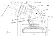
- Figure 1 shows a part of a hearing device 100 comprising a suspension 110 for a receiver 120 of the hearing device 100.
- the hearing device further comprises a sound outlet 160.
- the receiver 120 and/or the suspension 110 and/or the sound outlet 160 may be contained in a housing 170 of the hearing device 100. In an embodiment, the receiver 120 and the suspension and the sound outlet 160 are contained in the housing 170.
- the suspension comprises a first part 130 and a second part 140 and a vibration isolator 150 positioned between the first 130 and the second 140 parts.
- the vibration isolator 150 may be mechanically coupled to the first 130 and second parts 140.
- the mechanical coupling between the vibration isolator 150 and the first 130 and the second 140 parts is provided by molding the vibration isolator 150 and the first 130 and the second 140 parts in one piece.
- the mechanical coupling between the vibration isolator 150 and the first 130 and the second 140 parts may be chosen from the group consisting of vulcanizing, and casting, and injection molding.
- the mechanical coupling between the vibration isolator 150 and the first 130 and the second 140 parts is made by molding such as heat sealing or the like.
- first 130 and the second 140 parts and the vibration isolator 150 may be molded in an identical type of material such as an elastic material such as a rubber or silicone rubber or the like.
- the first 130 and the second 140 parts and the vibration isolator 150 may be molded in different materials.
- the vibration isolator 150 may be molded in a first material with a first elasticity and the first 130 and second 140 parts may be molded in a second material with a second elasticity.
- the second elasticity is smaller than the first elasticity.
- FIG. 2 shows a zoom of the vibration isolator 150.
- the vibration isolator 150 comprises an acoustic passage 151 and a damping 152 part enclosing said acoustic passage 151.
- the acoustic passage 151 provides an acoustic passage between the first 130 and second parts 140.
- the acoustic passage 151 is hollow and substantially tubular such as to enable sound to travel from the first part 130 to the second part 140.
- the acoustic passage may in another embodiment have a shape different from substantially tubular such as for example a tubular shape with a rectangular cross section.
- the acoustic passage 151 may have a cylindrical shape.
- a transverse dimension of the acoustic passage 151 in proximity to the first part 130 is smaller than the transverse dimension of the acoustic passage 151 in proximity to the second part 140.
- the diameter of a cylindrical shaped acoustic passage may be smaller in proximity to the first part 130 than the diameter of the cylindrical shaped acoustic passage in proximity to the second part 140.
- the transverse dimension of a tubular or substantially tubular acoustic passage 151 in proximity to the first part 130 is smaller than the external diameter of a tubular or substantially tubular snout of the receiver 120.
- the tubular or substantially tubular acoustic passage 151 ensures sufficient contact between the suspension 110 and the receiver 120 by being tight fitted around the snout of the receiver 120.
- the transverse dimension of a tubular or substantially tubular acoustic passage 151 in proximity to the second part 140 is equal to or substantially equal to (e.g. within 5%) the inner diameter of the sound outlet 160.
- the damping 152 part of the vibration isolator 150 is asymmetrical along a longitudinal and/or a transverse axis of the vibration isolator 150.
- Reference 153 denotes a wall thickness of the vibration isolator 150.
- the wall thickness 153 of the damping 152 part varies along the longitudinal and/or the transverse axis of the vibration isolator 150 and thereby provides the asymmetry of the damping 152 part.
- a material thickness of the damping 152 part varies along the longitudinal and/or the transverse axis of the vibration isolator 150.
- a Cartesian coordinate system is used to define a number of planes in the drawings such as an X-Y plane, a X-Z plane and a Y-Z plane.
- the wall thickness 153 of the damping 152 part is asymmetrical in the X-Z plane and the Y-Z plane of figure 1 .
- the wall thickness 153 of the damping 152 part is symmetrical in the X-Y plane of figure 1 .
- the damping part 152 further comprises a flexible 154 part and a substantially rigid 155 part.
- the substantially rigid part is positioned substantially intermediary between the first 130 and second 140 parts.
- the flexible 154 part is positioned between the second part 140 and the substantially rigid 155 part.
- the flexible 154 part is more flexible than the substantially rigid 155 part i.e. the flexible 154 part has a larger elasticity than the substantially rigid 155 part. This may be achieved by molding the flexible 154 part in a more elastic material than the substantially rigid 155 part. Alternatively or additionally, it may be achieved by molding the flexible 154 part with a smaller wall thickness 153 than the wall thickness 153 of the substantially rigid 155 part i.e. the material thickness of the flexible 154 part is smaller than the material thickness of the substantially rigid 155 part.
- the wall thickness of the substantially rigid part 155 is at least 3 times thicker than the smallest wall thickness of the flexible part 154.
- the flexible 154 and substantially rigid 155 parts ensures that the vibration pattern of the suspension is changed such that vibrations generated by the receiver 120 are directed in a direction away from the sound outlet 160 and substantially in one or more directions. Thereby, vibrations from the receiver 120 will be dampened and not propagate further in the hearing device 100 than to the vibration isolator.
- the vibration isolator 150 is freely suspended between the first 130 and second 140 parts of the suspension 110 i.e. the vibration isolator 150 is mechanically coupled to the hearing aid 100 by the first part 130 being mechanically coupled to the receiver 120 and the second part 140 being mechanically coupled to the sound outlet 160. Thereby, the vibration isolator 150 is able to move/vibrate freely in the three planes illustrated in figure 1 i.e. in the X-Y plane and the X-Z plane and the Y-Z plane.
- the substantially rigid 155 part of the damping part 150 is in an embodiment mechanically coupled directly to the first part 130 in order to ensure a stiff connection between the substantially rigid 155 part and the first part 130.
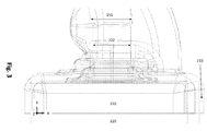
- Figure 3 shows a zoom of the first part 130.
- the first part 130 is adapted to enclose at least a part of the receiver 120.
- the first part 130 may comprise a rectangular part 210 adapted to enclose at least a part of the receiver body 220.
- an inner cross section of the rectangular part 210 is equal to or substantially equal to (e.g. 5% less than or 2% less than) an outer cross section of the enclosed part of the receiver body 220 in order to ensure sufficient physical contact between the rectangular part 210 and the receiver body 220. Thereby is achieved that the receiver is in physical contact with the first part 130 by a gripping force between the first part 130 and the receiver 120.
- an inner cross section of the acoustic passage 151 enclosing at least a part of a snout 222 of the receiver 120 is equal to or substantially equal to (e.g. 5% less than or 2% less than) an outer cross section of the enclosed part of the snout 222 in order to ensure sufficient physical contact between the acoustic passage 151 and the enclosed part of the snout 222.
- the snout 222 is in physical contact with the acoustic passage 151 via a gripping force between the snout 222 and the acoustic passage 151.
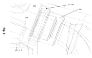
- Figure 4 shows a zoom of the second part 140.
- the second part 140 is adapted to enclose at least a part of the sound outlet 160.
- the second part may comprise a tubular part 141 such as a cylindrical part and a rectangular part 142 such as a square part.
- the rectangular part 142 ensures sufficient abutment between the rectangular part 142 and the housing 170.
- Both the tubular part 141 and the square part 142 comprises an inner cross section matching or substantially matching (e.g. 5% less than) the outer cross section of the sound outlet 160 in order to ensure sufficient physical contact between the tubular part 141 and the square part 142 and the sound outlet 160.
- the sound outlet 160 comprises a cylindrical outer cross section and thus, the inner cross section of the tubular part 141 and the rectangular part 142 are cylindrical thereby enabling reception of the sound outlet 160.
- the tubular part 141 and the rectangular part 142 may be molded in one piece or may be molded in two pieces and mechanically coupled together by e.g. welding.
- the first 130 and second 140 parts ensures a secure fastening of the suspension 110 to the housing 170 of the hearing aid 100 via the receiver 120 and the sound outlet 160.
- Figure 5 shows an embodiment of the suspension 110 wherein the vibration isolator 150 contains one or more structures 156, 157 adapted to receive one or more special features of the receiver 120 to thereby ensure correct placement of the receiver 120 with respect to the vibration isolator 150. Thereby, practical and easy assembly of the receiver 120 with the suspension 110 is enabled.
- the structures 156, 157 may be formed as recesses in the vibration isolator 150 adapted to receive substantially similar protrusions of the receiver 120.
- the invention further comprises a number of aspects according to the below mentioned items.
Landscapes
- Health & Medical Sciences (AREA)
- General Health & Medical Sciences (AREA)
- Neurosurgery (AREA)
- Otolaryngology (AREA)
- Physics & Mathematics (AREA)
- Engineering & Computer Science (AREA)
- Acoustics & Sound (AREA)
- Signal Processing (AREA)
- Vibration Prevention Devices (AREA)
Abstract
Description
- The present specification relates to a suspension for a hearing device receiver and to a method for producing a hearing aid with such a suspension. Additionally, the present specification relates to a hearing device comprising such a suspension.
- A hearing device comprises a microphone which receives acoustic signals. The received acoustic signals are processed where the processing may include amplification of the data. The processed signals are transmitted to a receiver of the hearing device which converts the processed signals into another acoustic signal e.g. with a larger amplitude at certain frequencies. The receiver broadcasts the other acoustic signal towards the tympanic membrane of a user of the hearing device.
- The broadcasting of the other acoustic signal can cause the receiver and the hearing device to vibrate which vibrations may be transmitted back to the microphone resulting in an unwanted feedback loop thereby putting a limitation on the amplification which the hearing device may deliver to the user.
- Therefore, it would be advantageous to reduce the transmission of vibrations generated by the receiver to the rest of the hearing device.
- It is an object of the present invention to provide a suspension for a hearing device receiver with an improved vibration reduction. The above-mentioned and other objects are fulfilled by a suspension for a hearing device receiver comprising a first part and a second part and a vibration isolator positioned between the first and the second parts and mechanically coupled to the first and second parts; wherein the first part is adapted to at least partly enclose the receiver; and the second part is adapted to at least partly enclose a sound outlet of the hearing device; and wherein the vibration isolator 150) comprises an acoustic passage and a damping part enclosing said acoustic passage; and wherein the acoustic passage part provides an acoustic passages between the first and second parts; and wherein the damping part of the vibration isolator is asymmetrical along a longitudinal and/or a transverse axis of the vibration isolator; and wherein the vibration isolator is freely suspended between the first and second parts.
- Thereby is achieved a suspension with a part (vibration isolator) which can move freely between the receiver and the sound outlet thus ensuring that vibration energy may be dispersed in a direction away from the housing i.e. in one or more of the free moving directions. Thus, the vibration energy is reduced to the housing from the receiver.
- In an embodiment, a material thickness of the damping part varying along the longitudinal and/or the transverse axis of the vibration isolator provides the asymmetry of the damping part..
- Thereby, the asymmetry of the vibration isolator is constructed by varying the thickness of the damping part. This ensures that parts of the vibration isolator comprising relatively thick walls are stiffer than parts comprising relatively thin walls.
- In an embodiment, the damping part further comprises a flexible part and a substantially rigid part positioned substantially intermediary between the first and second parts; and wherein the flexible part is more flexible than the substantially rigid part..
- Thereby, the suspension is adapted to change the vibration pattern of the suspension and the receiver such that the vibrations from the receiver are reduced to the housing and/or the sound outlet, but instead the vibration energy is dispersed in the free moving motion of the vibration isolator.
- In an embodiment, the flexible part is positioned between the second part and the substantially rigid pa rt.
- Thereby, the vibrations are dispersed in the substantially rigid damping part and the flexible part dampens further vibrations.
- In an embodiment, the first and the second parts and the vibration isolator are molded in one piece.
- Thereby, substantial optimal mechanical coupling between the first and second parts and the vibration isolator is obtained and thus, acoustic leakage between the parts may be eliminated.
- In an embodiment, the first and the second parts and the vibration isolator are molded in an elastic material.
- Thereby, the material of the suspension enables absorption of vibration energy in addition to the dispersion of the vibration energy due to the free movement of the vibration isolator.
- In an embodiment, the damping part is asymmetric in at least two planes.
- Thereby, the suspension is able to disperse the vibration energy in the asymmetric planes.
- In an embodiment, the damping part is asymmetric in two planes and symmetrical in a third plane.
- Thereby, the suspension is able to disperse the vibration energy in the asymmetric planes.
- In an embodiment, the asymmetric planes are the X-Z plane and the Y-Z plane, and the symmetric plane is the X-Y plane.
- Thereby, the suspension is able to disperse the vibration energy in the asymmetric planes.
- In an embodiment, the flexible part comprises a transverse material thickness smaller than the substantially rigid part.
- Thereby, the flexibility of the flexible part is obtained by decreasing the wall thickness with respect to the wall thickness of the substantially rigid part.
- In an embodiment, a material thickness of the damping part varies asymmetrically along the longitudinal and/or transverse axis of the vibration isolator.
- Thereby, the suspension is able to disperse the vibration energy in the asymmetric planes.
- In an embodiment, the material thickness of the flexible part is smaller than the material thickness of the substantially rigid part.
- Thereby, the suspension is able to disperse the vibration energy in the asymmetric planes.
- In an embodiment, the acoustic passage is hollow and substantially tubular, and wherein a transverse dimension of the acoustic passage in proximity to the first part is smaller than the transverse dimension of the acoustic passage in proximity to the second part such that the acoustic passage ensures sufficient contact between the suspension and the receiver.
- Thereby, the acoustic passage is adapted to fit tightly around the snout of the receiver thereby reducing the risk of leaks from the receiver through the acoustic passage.
- The invention further relates to a method of producing a hearing device comprising a receiver and a sound outlet and a suspension, the suspension comprising a first part and a second part and a vibration isolator positioned between and mechanically coupled to the first and second parts; the vibration isolator comprising a damping part enclosing an acoustic passage; the method comprising: coupling mechanically the first (130) part to the receiver (120); and coupling mechanically the second part to the sound outlet; such that the suspension provides an acoustic passage between the receiver and the sound outlet; and providing the damping part of the vibration isolator asymmetrically along a longitudinal and/or a transverse axis of the vibration isolator; and suspending the vibration isolator freely between the first and the second parts.
- The method and embodiments thereof has the same advantages as the suspension for the same reasons.
- The invention further relates to a hearing device comprising a receiver and a sound outlet and a suspension according to an embodiment of the suspension, wherein the receiver is mechanically coupled to the first part of the suspension and the sound outlet is mechanically coupled to the second part of the suspension.
- The hearing device and embodiments thereof has the same advantages as the suspension for the same reasons.
-
- Figure 1
- shows a part of a hearing device comprising a suspension for a receiver of the hearing device.
- Figure 2
- shows a zoom of the vibration isolator.
- Figure 3
- shows a zoom of the first part.
- Figure 4
- shows a zoom of the second part.
- Figure 5
- shows a view of the suspension focused on the first part.
- In the above and below, a hearing device may be selected from the group consisting of a hearing aid, a hearing prosthesis, and the like. Examples of a hearing device may include a behind the ear (BTE) hearing aid and a in the ear (ITE) hearing aid.
-
Figure 1 shows a part of ahearing device 100 comprising asuspension 110 for areceiver 120 of thehearing device 100. The hearing device further comprises asound outlet 160. Thereceiver 120 and/or thesuspension 110 and/or thesound outlet 160 may be contained in ahousing 170 of thehearing device 100. In an embodiment, thereceiver 120 and the suspension and thesound outlet 160 are contained in thehousing 170. - The suspension comprises a
first part 130 and asecond part 140 and a vibration isolator 150 positioned between the first 130 and the second 140 parts. The vibration isolator 150 may be mechanically coupled to the first 130 andsecond parts 140. - In an embodiment, the mechanical coupling between the vibration isolator 150 and the first 130 and the second 140 parts is provided by molding the vibration isolator 150 and the first 130 and the second 140 parts in one piece.
- In an embodiment, the mechanical coupling between the vibration isolator 150 and the first 130 and the second 140 parts may be chosen from the group consisting of vulcanizing, and casting, and injection molding.
- In an embodiment, the mechanical coupling between the vibration isolator 150 and the first 130 and the second 140 parts is made by molding such as heat sealing or the like.
- In an embodiment, the first 130 and the second 140 parts and the vibration isolator 150 may be molded in an identical type of material such as an elastic material such as a rubber or silicone rubber or the like.
- In an embodiment, the first 130 and the second 140 parts and the vibration isolator 150 may be molded in different materials. In an embodiment, the vibration isolator 150 may be molded in a first material with a first elasticity and the first 130 and second 140 parts may be molded in a second material with a second elasticity. In an embodiment, the second elasticity is smaller than the first elasticity.
-
Figure 2 shows a zoom of the vibration isolator 150. The vibration isolator 150 comprises anacoustic passage 151 and a damping 152 part enclosing saidacoustic passage 151. - The
acoustic passage 151 provides an acoustic passage between the first 130 andsecond parts 140. In an embodiment, theacoustic passage 151 is hollow and substantially tubular such as to enable sound to travel from thefirst part 130 to thesecond part 140. The acoustic passage may in another embodiment have a shape different from substantially tubular such as for example a tubular shape with a rectangular cross section. In an embodiment, theacoustic passage 151 may have a cylindrical shape. - In an embodiment, a transverse dimension of the
acoustic passage 151 in proximity to thefirst part 130 is smaller than the transverse dimension of theacoustic passage 151 in proximity to thesecond part 140. For example, the diameter of a cylindrical shaped acoustic passage may be smaller in proximity to thefirst part 130 than the diameter of the cylindrical shaped acoustic passage in proximity to thesecond part 140. - In an embodiment, the transverse dimension of a tubular or substantially tubular
acoustic passage 151 in proximity to thefirst part 130 is smaller than the external diameter of a tubular or substantially tubular snout of thereceiver 120. Thereby, the tubular or substantially tubularacoustic passage 151 ensures sufficient contact between thesuspension 110 and thereceiver 120 by being tight fitted around the snout of thereceiver 120. - In an embodiment, the transverse dimension of a tubular or substantially tubular
acoustic passage 151 in proximity to thesecond part 140 is equal to or substantially equal to (e.g. within 5%) the inner diameter of thesound outlet 160. - The damping 152 part of the vibration isolator 150 is asymmetrical along a longitudinal and/or a transverse axis of the vibration isolator 150.
Reference 153 denotes a wall thickness of the vibration isolator 150. - In an embodiment, the
wall thickness 153 of the damping 152 part varies along the longitudinal and/or the transverse axis of the vibration isolator 150 and thereby provides the asymmetry of the damping 152 part. Thus, a material thickness of the damping 152 part varies along the longitudinal and/or the transverse axis of the vibration isolator 150. - In an embodiment, a Cartesian coordinate system is used to define a number of planes in the drawings such as an X-Y plane, a X-Z plane and a Y-Z plane.
- In an embodiment, the
wall thickness 153 of the damping 152 part is asymmetrical in the X-Z plane and the Y-Z plane offigure 1 . - In an additional embodiment, the
wall thickness 153 of the damping 152 part is symmetrical in the X-Y plane offigure 1 . - In an embodiment, the damping
part 152 further comprises a flexible 154 part and a substantially rigid 155 part. The substantially rigid part is positioned substantially intermediary between the first 130 and second 140 parts. The flexible 154 part is positioned between thesecond part 140 and the substantially rigid 155 part. - In an embodiment, the flexible 154 part is more flexible than the substantially rigid 155 part i.e. the flexible 154 part has a larger elasticity than the substantially rigid 155 part. This may be achieved by molding the flexible 154 part in a more elastic material than the substantially rigid 155 part. Alternatively or additionally, it may be achieved by molding the flexible 154 part with a
smaller wall thickness 153 than thewall thickness 153 of the substantially rigid 155 part i.e. the material thickness of the flexible 154 part is smaller than the material thickness of the substantially rigid 155 part. - In an embodiment, the wall thickness of the substantially
rigid part 155 is at least 3 times thicker than the smallest wall thickness of theflexible part 154. - The flexible 154 and substantially rigid 155 parts ensures that the vibration pattern of the suspension is changed such that vibrations generated by the
receiver 120 are directed in a direction away from thesound outlet 160 and substantially in one or more directions. Thereby, vibrations from thereceiver 120 will be dampened and not propagate further in thehearing device 100 than to the vibration isolator. - The vibration isolator 150 is freely suspended between the first 130 and second 140 parts of the
suspension 110 i.e. the vibration isolator 150 is mechanically coupled to thehearing aid 100 by thefirst part 130 being mechanically coupled to thereceiver 120 and thesecond part 140 being mechanically coupled to thesound outlet 160. Thereby, the vibration isolator 150 is able to move/vibrate freely in the three planes illustrated infigure 1 i.e. in the X-Y plane and the X-Z plane and the Y-Z plane. - The substantially rigid 155 part of the damping part 150 is in an embodiment mechanically coupled directly to the
first part 130 in order to ensure a stiff connection between the substantially rigid 155 part and thefirst part 130. -
Figure 3 shows a zoom of thefirst part 130. Thefirst part 130 is adapted to enclose at least a part of thereceiver 120. Thefirst part 130 may comprise arectangular part 210 adapted to enclose at least a part of thereceiver body 220. - In an embodiment, an inner cross section of the
rectangular part 210 is equal to or substantially equal to (e.g. 5% less than or 2% less than) an outer cross section of the enclosed part of thereceiver body 220 in order to ensure sufficient physical contact between therectangular part 210 and thereceiver body 220. Thereby is achieved that the receiver is in physical contact with thefirst part 130 by a gripping force between thefirst part 130 and thereceiver 120. - In an additional or alternative embodiment, an inner cross section of the
acoustic passage 151 enclosing at least a part of asnout 222 of thereceiver 120 is equal to or substantially equal to (e.g. 5% less than or 2% less than) an outer cross section of the enclosed part of thesnout 222 in order to ensure sufficient physical contact between theacoustic passage 151 and the enclosed part of thesnout 222. Thereby is achieved that thesnout 222 is in physical contact with theacoustic passage 151 via a gripping force between thesnout 222 and theacoustic passage 151. -
Figure 4 shows a zoom of thesecond part 140. Thesecond part 140 is adapted to enclose at least a part of thesound outlet 160. The second part may comprise atubular part 141 such as a cylindrical part and arectangular part 142 such as a square part. Therectangular part 142 ensures sufficient abutment between therectangular part 142 and thehousing 170. Both thetubular part 141 and thesquare part 142 comprises an inner cross section matching or substantially matching (e.g. 5% less than) the outer cross section of thesound outlet 160 in order to ensure sufficient physical contact between thetubular part 141 and thesquare part 142 and thesound outlet 160. In an embodiment, thesound outlet 160 comprises a cylindrical outer cross section and thus, the inner cross section of thetubular part 141 and therectangular part 142 are cylindrical thereby enabling reception of thesound outlet 160. - The
tubular part 141 and therectangular part 142 may be molded in one piece or may be molded in two pieces and mechanically coupled together by e.g. welding. - The first 130 and second 140 parts ensures a secure fastening of the
suspension 110 to thehousing 170 of thehearing aid 100 via thereceiver 120 and thesound outlet 160. -
Figure 5 shows an embodiment of thesuspension 110 wherein the vibration isolator 150 contains one ormore structures receiver 120 to thereby ensure correct placement of thereceiver 120 with respect to the vibration isolator 150. Thereby, practical and easy assembly of thereceiver 120 with thesuspension 110 is enabled. In an embodiment, thestructures receiver 120. - The invention further comprises a number of aspects according to the below mentioned items.
-
- 1. A suspension (110) for a hearing device receiver (120) comprising
- a first part (130) and a second part (140) and a vibration isolator (150) positioned between the first (130) and the second (140) parts and mechanically coupled to the first (130) and second (140) parts;
- wherein the first part (130) is adapted to at least partly enclose the receiver (120); and
- the second part (140) is adapted to at least partly enclose a sound outlet (160) of the hearing device (100); and
- wherein the vibration isolator (150) comprises an acoustic passage (151) and a damping (152) part enclosing said acoustic passage (151); and
- wherein the acoustic passage (151) part provides an acoustic passages between the first (130) and second parts (140); and
- wherein the damping (152) part of the vibration isolator (150) is asymmetrical along a longitudinal and/or a transverse axis of the vibration isolator (150); and
- wherein the vibration isolator (150) is freely suspended between the first and second pa rts.
- 2. A suspension according to item 1, wherein a material thickness (153) of the damping (152) part varying along the longitudinal and/or the transverse axis of the vibration isolator (150) provides the asymmetry of the damping (152) part.
- 3. A suspension according to item 1 or 2, wherein the damping part (152) further comprises a flexible (154) part and a substantially rigid (155) part positioned substantially intermediary between the first (130) and second (140) parts; and wherein the flexible (154) part is more flexible than the substantially rigid (155) part.
- 4. A suspension according to item 3, wherein the flexible (154) part is positioned between the second (140) part and the substantially rigid (155) part.
- 5. A suspension according to anyone of the preceding items, wherein the first (130) and the second (140) parts and the vibration isolator (150) are molded in one piece.
- 6. A suspension according to anyone of the preceding items, wherein the first (130) and the second (140) parts and the vibration isolator (150) are molded in an elastic material.
- 7. A suspension according to anyone of the preceding items, wherein the damping part is asymmetric in at least two planes.
- 8. A suspension according to anyone of the preceding items, wherein the damping part is asymmetric in two planes and symmetrical in a third plane.
- 9. A suspension according to item 8, wherein the asymmetric planes are the X-Z plane and the Y-Z plane, and the symmetric plane is the X-Y plane.
- 10. A suspension according to item 3 or 4, wherein the flexible (154) part comprises a transverse material thickness smaller than the substantially rigid (155) part.
- 11. A suspension according to anyone of the preceding items, wherein a material thickness of the damping part (152) varies asymmetrically along the longitudinal and/or transverse axis of the vibration isolator (150).
- 12. A suspension according to item 3 or 4, wherein the material thickness of the flexible (154) part is smaller than the material thickness of the substantially rigid (155) part.
- 13. A suspension according to anyone of the preceding items, wherein the acoustic passage (151) is hollow and substantially tubular, and wherein a transverse dimension of the acoustic passage in proximity to the first (130) part is smaller than the transverse dimension of the acoustic passage in proximity to the second (140) part such that the acoustic passage (151) ensures sufficient contact between the suspension (110) and the receiver (120).
- 14. A method of producing a hearing device (100) comprising a receiver (120) and a sound outlet (160) and a suspension (110), the suspension (110) comprising a first (130) part and a second (140) part and a vibration isolator (150) positioned between and mechanically coupled to the first (130) and second (140) parts; the vibration isolator (150) comprising a damping (152) part enclosing an acoustic passage (151); the method comprising:
- coupling mechanically the first (130) part to the receiver (120); and
- coupling mechanically the second (140) part to the sound outlet (160);
- such that the suspension (110) provides an acoustic passage between the receiver (120) and the sound outlet (160); and
- providing the damping (152) part of the vibration isolator (150) asymmetrically along a longitudinal and/or a transverse axis of the vibration isolator (150); and
- suspending the vibration isolator (150) freely between the first (130) and the second (140) parts.
- 15. A method according to item 14, wherein the asymmetry of the damping (152) part is provided by varying a material thickness (153) of the damping (152) part along the longitudinal and/or the transverse axis of the vibration isolator (150).
- 16. A method according to item 14 or 15, wherein the damping (152) part is further provided with a flexible (154) part and a substantially rigid (155) part; and wherein the flexible (154) part is more flexible than the substantially rigid (155) part.
- 17. A method according to anyone of items 14 to 16, wherein the method further comprises casting the first (130) and the second (140) parts and the vibration isolator (150) in one piece.
- 18. A method according to anyone of items 14 to 17, wherein the method further comprises positioning the first (130) part at a non-parallel angle to the second (140) part.
- 19. A hearing device (100) comprising a receiver (120) and a sound outlet (160) and a suspension (110) according to anyone of items 1 to 13, wherein the receiver (120) is mechanically coupled to the first (130) part of the suspension (110) and the sound outlet (160) is mechanically coupled to the second (140) part of the suspension (110).
Claims (15)
- A suspension (110) for a hearing device receiver (120) comprisinga. a first part (130) and a second part (140) and a vibration isolator (150) positioned between the first (130) and the second (140) parts and mechanically coupled to the first (130) and second (140) parts;b. wherein the first part (130) is adapted to at least partly enclose the receiver (120); andc. the second part (140) is adapted to at least partly enclose a sound outlet (160) of the hearing device (100); andd. wherein the vibration isolator (150) comprises an acoustic passage (151) and a damping (152) part enclosing said acoustic passage (151); ande. wherein the acoustic passage (151) part provides an acoustic passages between the first (130) and second parts (140); andf. wherein the damping (152) part of the vibration isolator (150) is asymmetrical along a longitudinal and/or a transverse axis of the vibration isolator (150); andg. wherein the vibration isolator (150) is freely suspended between the first and second pa rts.
- A suspension according to claim 1, wherein a material thickness (153) of the damping (152) part varying along the longitudinal and/or the transverse axis of the vibration isolator (150) provides the asymmetry of the damping (152) part.
- A suspension according to claim 1 or 2, wherein the damping part (152) further comprises a flexible (154) part and a substantially rigid (155) part positioned substantially intermediary between the first (130) and second (140) parts; and wherein the flexible (154) part is more flexible than the substantially rigid (155) part.
- A suspension according to claim 3, wherein the flexible (154) part is positioned between the second (140) part and the substantially rigid (155) part.
- A suspension according to anyone of the preceding claims, wherein the damping part is asymmetric in at least two planes.
- A suspension according to claim 5, wherein the asymmetric planes are the X-Z plane and the Y-Z plane, and a symmetric plane is the X-Y plane.
- A suspension according to claim 3 or 4, wherein the flexible (154) part comprises a transverse material thickness smaller than a transverse thickness of the substantially rigid (155) part.
- A suspension according to anyone of the preceding claims, wherein a material thickness of the damping part (152) varies asymmetrically along the longitudinal and/or transverse axis of the vibration isolator (150).
- A suspension according to anyone of the preceding claims, wherein the acoustic passage (151) is hollow and substantially tubular, and wherein a transverse dimension of the acoustic passage in proximity to the first (130) part is smaller than the transverse dimension of the acoustic passage in proximity to the second (140) part such that the acoustic passage (151) ensures sufficient contact between the suspension (110) and the receiver (120).
- A method of producing a hearing device (100) comprising a receiver (120) and a sound outlet (160) and a suspension (110), the suspension (110) comprising a first (130) part and a second (140) part and a vibration isolator (150) positioned between and mechanically coupled to the first (130) and second (140) parts; the vibration isolator (150) comprising a damping (152) part enclosing an acoustic passage (151); the method comprising:a. coupling mechanically the first (130) part to the receiver (120); andb. coupling mechanically the second (140) part to the sound outlet (160);c. such that the suspension (110) provides an acoustic passage between the receiver (120) and the sound outlet (160); andd. providing the damping (152) part of the vibration isolator (150) asymmetrically along a longitudinal and/or a transverse axis of the vibration isolator (150); ande. suspending the vibration isolator (150) freely between the first (130) and the second (140) parts.
- A method according to claim 10, wherein the asymmetry of the damping (152) part is provided by varying a material thickness (153) of the damping (152) part along the longitudinal and/or the transverse axis of the vibration isolator (150).
- A method according to claim 10 or 11, wherein the damping (152) part is further provided with a flexible (154) part and a substantially rigid (155) part; and wherein the flexible (154) part is more flexible than the substantially rigid (155) part.
- A method according to anyone of claims 10 to 12, wherein the method further comprises casting the first (130) and the second (140) parts and the vibration isolator (150) in one piece.
- A method according to anyone of claims 10 to 13, wherein the method further comprises positioning the first (130) part at a non-parallel angle to the second (140) part.
- A hearing device (100) comprising a receiver (120) and a sound outlet (160) and a suspension (110) according to anyone of claims 1 to 9, wherein the receiver (120) is mechanically coupled to the first (130) part of the suspension (110) and the sound outlet (160) is mechanically coupled to the second (140) part of the suspension (110).
Priority Applications (5)
| Application Number | Priority Date | Filing Date | Title |
|---|---|---|---|
| EP10190874.7A EP2453674B1 (en) | 2010-11-11 | 2010-11-11 | A suspension for a hearing device receiver, and a method of producing a hearing device, and a hearing device |
| DK10190874.7T DK2453674T3 (en) | 2010-11-11 | 2010-11-11 | Suspension for a hearing aid recipient, method of manufacturing a hearing aid and hearing aid |
| CN201180054631.6A CN103210666B (en) | 2010-11-11 | 2011-11-08 | Suspension for earpiece of hearing device, method of manufacturing hearing device, and hearing device |
| PCT/EP2011/069657 WO2012062761A1 (en) | 2010-11-11 | 2011-11-08 | A suspension for a hearing device receiver, and a method of producing a hearing device, and a hearing device |
| JP2013538167A JP5715707B2 (en) | 2010-11-11 | 2011-11-08 | Hearing device suspension, hearing device manufacturing method, and hearing device |
Applications Claiming Priority (1)
| Application Number | Priority Date | Filing Date | Title |
|---|---|---|---|
| EP10190874.7A EP2453674B1 (en) | 2010-11-11 | 2010-11-11 | A suspension for a hearing device receiver, and a method of producing a hearing device, and a hearing device |
Publications (2)
| Publication Number | Publication Date |
|---|---|
| EP2453674A1 true EP2453674A1 (en) | 2012-05-16 |
| EP2453674B1 EP2453674B1 (en) | 2015-09-23 |
Family
ID=43566686
Family Applications (1)
| Application Number | Title | Priority Date | Filing Date |
|---|---|---|---|
| EP10190874.7A Active EP2453674B1 (en) | 2010-11-11 | 2010-11-11 | A suspension for a hearing device receiver, and a method of producing a hearing device, and a hearing device |
Country Status (2)
| Country | Link |
|---|---|
| EP (1) | EP2453674B1 (en) |
| DK (1) | DK2453674T3 (en) |
Citations (4)
| Publication number | Priority date | Publication date | Assignee | Title |
|---|---|---|---|---|
| WO2001043498A1 (en) * | 1999-12-10 | 2001-06-14 | Sonic Innovations, Inc. | Receiver suspension device for an in-the-canal hearing aid |
| WO2004008803A1 (en) * | 2002-07-12 | 2004-01-22 | Oticon A/S | Suspension means for transducer |
| WO2005055653A2 (en) * | 2003-12-05 | 2005-06-16 | Oticon A/S | Communication device with structural part |
| WO2007011421A1 (en) * | 2005-07-15 | 2007-01-25 | Knowles Electronics, Llc | Shock resistant and vibration isolated electroacoustical trandsucer assembly |
Family Cites Families (2)
| Publication number | Priority date | Publication date | Assignee | Title |
|---|---|---|---|---|
| US7403629B1 (en) * | 1999-05-05 | 2008-07-22 | Sarnoff Corporation | Disposable modular hearing aid |
| DE102006029819A1 (en) * | 2006-06-28 | 2008-01-03 | Siemens Audiologische Technik Gmbh | Hearing aid with a fastening for a receiver tube |
-
2010
- 2010-11-11 EP EP10190874.7A patent/EP2453674B1/en active Active
- 2010-11-11 DK DK10190874.7T patent/DK2453674T3/en active
Patent Citations (4)
| Publication number | Priority date | Publication date | Assignee | Title |
|---|---|---|---|---|
| WO2001043498A1 (en) * | 1999-12-10 | 2001-06-14 | Sonic Innovations, Inc. | Receiver suspension device for an in-the-canal hearing aid |
| WO2004008803A1 (en) * | 2002-07-12 | 2004-01-22 | Oticon A/S | Suspension means for transducer |
| WO2005055653A2 (en) * | 2003-12-05 | 2005-06-16 | Oticon A/S | Communication device with structural part |
| WO2007011421A1 (en) * | 2005-07-15 | 2007-01-25 | Knowles Electronics, Llc | Shock resistant and vibration isolated electroacoustical trandsucer assembly |
Also Published As
| Publication number | Publication date |
|---|---|
| DK2453674T3 (en) | 2015-10-05 |
| EP2453674B1 (en) | 2015-09-23 |
Similar Documents
| Publication | Publication Date | Title |
|---|---|---|
| US4440982A (en) | Hearing aid | |
| KR102012860B1 (en) | earphone | |
| US10284976B2 (en) | Hearing aid | |
| US20070036378A1 (en) | Shock resistant and vibration isolated electroacoustical transducer assembly | |
| CN106878898B (en) | Hearing aid including receiver assembly | |
| WO2010004624A1 (en) | Earphone | |
| US11425513B2 (en) | Suspension assembly for hearing aid receiver | |
| EP3058761B1 (en) | Suspension for a hearing device receiver | |
| US8103031B2 (en) | Hearing device sound emission tube with a 2-component design | |
| EP2753102A1 (en) | Hearing aid with an in-the-ear component | |
| US8737657B2 (en) | Suspension for a hearing device receiver, and a method of producing a hearing device, and a hearing device | |
| WO2012062761A1 (en) | A suspension for a hearing device receiver, and a method of producing a hearing device, and a hearing device | |
| US7324653B2 (en) | Suspension means for transducer | |
| EP2453674B1 (en) | A suspension for a hearing device receiver, and a method of producing a hearing device, and a hearing device | |
| US10873818B2 (en) | Damping device for a receiver of a hearing instrument and hearing instrument having such a damping device | |
| EP4694183A1 (en) | Electroacoustic transducer and headphone | |
| US8855346B2 (en) | Hearing device with reduced acoustic feedback due to vibration-related shortening of the hearing device | |
| JP7502076B2 (en) | Cartilage conduction earphones and listening devices | |
| JP7406369B2 (en) | Electroacoustic transducers and audio equipment | |
| CN110858946A (en) | Elastic damping element for the earpiece of a hearing aid and hearing aid | |
| US20080298620A1 (en) | Wearing hook with metal section for a hearing device | |
| CN118843057A (en) | Hearing device and associated binaural hearing system |
Legal Events
| Date | Code | Title | Description |
|---|---|---|---|
| PUAI | Public reference made under article 153(3) epc to a published international application that has entered the european phase |
Free format text: ORIGINAL CODE: 0009012 |
|
| AK | Designated contracting states |
Kind code of ref document: A1 Designated state(s): AL AT BE BG CH CY CZ DE DK EE ES FI FR GB GR HR HU IE IS IT LI LT LU LV MC MK MT NL NO PL PT RO RS SE SI SK SM TR |
|
| AX | Request for extension of the european patent |
Extension state: BA ME |
|
| 17P | Request for examination filed |
Effective date: 20121115 |
|
| 17Q | First examination report despatched |
Effective date: 20130315 |
|
| GRAP | Despatch of communication of intention to grant a patent |
Free format text: ORIGINAL CODE: EPIDOSNIGR1 |
|
| INTG | Intention to grant announced |
Effective date: 20150430 |
|
| GRAS | Grant fee paid |
Free format text: ORIGINAL CODE: EPIDOSNIGR3 |
|
| GRAA | (expected) grant |
Free format text: ORIGINAL CODE: 0009210 |
|
| AK | Designated contracting states |
Kind code of ref document: B1 Designated state(s): AL AT BE BG CH CY CZ DE DK EE ES FI FR GB GR HR HU IE IS IT LI LT LU LV MC MK MT NL NO PL PT RO RS SE SI SK SM TR |
|
| REG | Reference to a national code |
Ref country code: GB Ref legal event code: FG4D |
|
| REG | Reference to a national code |
Ref country code: CH Ref legal event code: EP |
|
| REG | Reference to a national code |
Ref country code: DK Ref legal event code: T3 Effective date: 20150930 |
|
| REG | Reference to a national code |
Ref country code: AT Ref legal event code: REF Ref document number: 751781 Country of ref document: AT Kind code of ref document: T Effective date: 20151015 |
|
| REG | Reference to a national code |
Ref country code: IE Ref legal event code: FG4D |
|
| REG | Reference to a national code |
Ref country code: DE Ref legal event code: R096 Ref document number: 602010027685 Country of ref document: DE |
|
| REG | Reference to a national code |
Ref country code: FR Ref legal event code: PLFP Year of fee payment: 6 |
|
| REG | Reference to a national code |
Ref country code: NL Ref legal event code: MP Effective date: 20150923 |
|
| PG25 | Lapsed in a contracting state [announced via postgrant information from national office to epo] |
Ref country code: FI Free format text: LAPSE BECAUSE OF FAILURE TO SUBMIT A TRANSLATION OF THE DESCRIPTION OR TO PAY THE FEE WITHIN THE PRESCRIBED TIME-LIMIT Effective date: 20150923 Ref country code: LV Free format text: LAPSE BECAUSE OF FAILURE TO SUBMIT A TRANSLATION OF THE DESCRIPTION OR TO PAY THE FEE WITHIN THE PRESCRIBED TIME-LIMIT Effective date: 20150923 Ref country code: LT Free format text: LAPSE BECAUSE OF FAILURE TO SUBMIT A TRANSLATION OF THE DESCRIPTION OR TO PAY THE FEE WITHIN THE PRESCRIBED TIME-LIMIT Effective date: 20150923 Ref country code: NO Free format text: LAPSE BECAUSE OF FAILURE TO SUBMIT A TRANSLATION OF THE DESCRIPTION OR TO PAY THE FEE WITHIN THE PRESCRIBED TIME-LIMIT Effective date: 20151223 Ref country code: GR Free format text: LAPSE BECAUSE OF FAILURE TO SUBMIT A TRANSLATION OF THE DESCRIPTION OR TO PAY THE FEE WITHIN THE PRESCRIBED TIME-LIMIT Effective date: 20151224 |
|
| REG | Reference to a national code |
Ref country code: LT Ref legal event code: MG4D |
|
| REG | Reference to a national code |
Ref country code: AT Ref legal event code: MK05 Ref document number: 751781 Country of ref document: AT Kind code of ref document: T Effective date: 20150923 |
|
| PG25 | Lapsed in a contracting state [announced via postgrant information from national office to epo] |
Ref country code: RS Free format text: LAPSE BECAUSE OF FAILURE TO SUBMIT A TRANSLATION OF THE DESCRIPTION OR TO PAY THE FEE WITHIN THE PRESCRIBED TIME-LIMIT Effective date: 20150923 Ref country code: SE Free format text: LAPSE BECAUSE OF FAILURE TO SUBMIT A TRANSLATION OF THE DESCRIPTION OR TO PAY THE FEE WITHIN THE PRESCRIBED TIME-LIMIT Effective date: 20150923 Ref country code: HR Free format text: LAPSE BECAUSE OF FAILURE TO SUBMIT A TRANSLATION OF THE DESCRIPTION OR TO PAY THE FEE WITHIN THE PRESCRIBED TIME-LIMIT Effective date: 20150923 |
|
| PG25 | Lapsed in a contracting state [announced via postgrant information from national office to epo] |
Ref country code: NL Free format text: LAPSE BECAUSE OF FAILURE TO SUBMIT A TRANSLATION OF THE DESCRIPTION OR TO PAY THE FEE WITHIN THE PRESCRIBED TIME-LIMIT Effective date: 20150923 |
|
| PG25 | Lapsed in a contracting state [announced via postgrant information from national office to epo] |
Ref country code: IT Free format text: LAPSE BECAUSE OF FAILURE TO SUBMIT A TRANSLATION OF THE DESCRIPTION OR TO PAY THE FEE WITHIN THE PRESCRIBED TIME-LIMIT Effective date: 20150923 Ref country code: CZ Free format text: LAPSE BECAUSE OF FAILURE TO SUBMIT A TRANSLATION OF THE DESCRIPTION OR TO PAY THE FEE WITHIN THE PRESCRIBED TIME-LIMIT Effective date: 20150923 Ref country code: ES Free format text: LAPSE BECAUSE OF FAILURE TO SUBMIT A TRANSLATION OF THE DESCRIPTION OR TO PAY THE FEE WITHIN THE PRESCRIBED TIME-LIMIT Effective date: 20150923 Ref country code: IS Free format text: LAPSE BECAUSE OF FAILURE TO SUBMIT A TRANSLATION OF THE DESCRIPTION OR TO PAY THE FEE WITHIN THE PRESCRIBED TIME-LIMIT Effective date: 20160123 Ref country code: SK Free format text: LAPSE BECAUSE OF FAILURE TO SUBMIT A TRANSLATION OF THE DESCRIPTION OR TO PAY THE FEE WITHIN THE PRESCRIBED TIME-LIMIT Effective date: 20150923 Ref country code: EE Free format text: LAPSE BECAUSE OF FAILURE TO SUBMIT A TRANSLATION OF THE DESCRIPTION OR TO PAY THE FEE WITHIN THE PRESCRIBED TIME-LIMIT Effective date: 20150923 |
|
| PG25 | Lapsed in a contracting state [announced via postgrant information from national office to epo] |
Ref country code: RO Free format text: LAPSE BECAUSE OF FAILURE TO SUBMIT A TRANSLATION OF THE DESCRIPTION OR TO PAY THE FEE WITHIN THE PRESCRIBED TIME-LIMIT Effective date: 20150923 Ref country code: PL Free format text: LAPSE BECAUSE OF FAILURE TO SUBMIT A TRANSLATION OF THE DESCRIPTION OR TO PAY THE FEE WITHIN THE PRESCRIBED TIME-LIMIT Effective date: 20150923 Ref country code: PT Free format text: LAPSE BECAUSE OF FAILURE TO SUBMIT A TRANSLATION OF THE DESCRIPTION OR TO PAY THE FEE WITHIN THE PRESCRIBED TIME-LIMIT Effective date: 20160125 Ref country code: AT Free format text: LAPSE BECAUSE OF FAILURE TO SUBMIT A TRANSLATION OF THE DESCRIPTION OR TO PAY THE FEE WITHIN THE PRESCRIBED TIME-LIMIT Effective date: 20150923 |
|
| REG | Reference to a national code |
Ref country code: DE Ref legal event code: R097 Ref document number: 602010027685 Country of ref document: DE |
|
| PG25 | Lapsed in a contracting state [announced via postgrant information from national office to epo] |
Ref country code: LU Free format text: LAPSE BECAUSE OF FAILURE TO SUBMIT A TRANSLATION OF THE DESCRIPTION OR TO PAY THE FEE WITHIN THE PRESCRIBED TIME-LIMIT Effective date: 20151111 Ref country code: MC Free format text: LAPSE BECAUSE OF FAILURE TO SUBMIT A TRANSLATION OF THE DESCRIPTION OR TO PAY THE FEE WITHIN THE PRESCRIBED TIME-LIMIT Effective date: 20150923 |
|
| PLBE | No opposition filed within time limit |
Free format text: ORIGINAL CODE: 0009261 |
|
| STAA | Information on the status of an ep patent application or granted ep patent |
Free format text: STATUS: NO OPPOSITION FILED WITHIN TIME LIMIT |
|
| REG | Reference to a national code |
Ref country code: IE Ref legal event code: MM4A |
|
| 26N | No opposition filed |
Effective date: 20160624 |
|
| PG25 | Lapsed in a contracting state [announced via postgrant information from national office to epo] |
Ref country code: IE Free format text: LAPSE BECAUSE OF NON-PAYMENT OF DUE FEES Effective date: 20151111 |
|
| REG | Reference to a national code |
Ref country code: FR Ref legal event code: PLFP Year of fee payment: 7 |
|
| PG25 | Lapsed in a contracting state [announced via postgrant information from national office to epo] |
Ref country code: SI Free format text: LAPSE BECAUSE OF FAILURE TO SUBMIT A TRANSLATION OF THE DESCRIPTION OR TO PAY THE FEE WITHIN THE PRESCRIBED TIME-LIMIT Effective date: 20150923 |
|
| PG25 | Lapsed in a contracting state [announced via postgrant information from national office to epo] |
Ref country code: BE Free format text: LAPSE BECAUSE OF FAILURE TO SUBMIT A TRANSLATION OF THE DESCRIPTION OR TO PAY THE FEE WITHIN THE PRESCRIBED TIME-LIMIT Effective date: 20150923 |
|
| PG25 | Lapsed in a contracting state [announced via postgrant information from national office to epo] |
Ref country code: SM Free format text: LAPSE BECAUSE OF FAILURE TO SUBMIT A TRANSLATION OF THE DESCRIPTION OR TO PAY THE FEE WITHIN THE PRESCRIBED TIME-LIMIT Effective date: 20150923 Ref country code: HU Free format text: LAPSE BECAUSE OF FAILURE TO SUBMIT A TRANSLATION OF THE DESCRIPTION OR TO PAY THE FEE WITHIN THE PRESCRIBED TIME-LIMIT; INVALID AB INITIO Effective date: 20101111 Ref country code: BG Free format text: LAPSE BECAUSE OF FAILURE TO SUBMIT A TRANSLATION OF THE DESCRIPTION OR TO PAY THE FEE WITHIN THE PRESCRIBED TIME-LIMIT Effective date: 20150923 |
|
| PG25 | Lapsed in a contracting state [announced via postgrant information from national office to epo] |
Ref country code: CY Free format text: LAPSE BECAUSE OF FAILURE TO SUBMIT A TRANSLATION OF THE DESCRIPTION OR TO PAY THE FEE WITHIN THE PRESCRIBED TIME-LIMIT Effective date: 20150923 |
|
| PG25 | Lapsed in a contracting state [announced via postgrant information from national office to epo] |
Ref country code: MT Free format text: LAPSE BECAUSE OF FAILURE TO SUBMIT A TRANSLATION OF THE DESCRIPTION OR TO PAY THE FEE WITHIN THE PRESCRIBED TIME-LIMIT Effective date: 20150923 Ref country code: TR Free format text: LAPSE BECAUSE OF FAILURE TO SUBMIT A TRANSLATION OF THE DESCRIPTION OR TO PAY THE FEE WITHIN THE PRESCRIBED TIME-LIMIT Effective date: 20150923 |
|
| REG | Reference to a national code |
Ref country code: FR Ref legal event code: PLFP Year of fee payment: 8 |
|
| PG25 | Lapsed in a contracting state [announced via postgrant information from national office to epo] |
Ref country code: MK Free format text: LAPSE BECAUSE OF FAILURE TO SUBMIT A TRANSLATION OF THE DESCRIPTION OR TO PAY THE FEE WITHIN THE PRESCRIBED TIME-LIMIT Effective date: 20150923 |
|
| PG25 | Lapsed in a contracting state [announced via postgrant information from national office to epo] |
Ref country code: AL Free format text: LAPSE BECAUSE OF FAILURE TO SUBMIT A TRANSLATION OF THE DESCRIPTION OR TO PAY THE FEE WITHIN THE PRESCRIBED TIME-LIMIT Effective date: 20150923 |
|
| PGFP | Annual fee paid to national office [announced via postgrant information from national office to epo] |
Ref country code: DK Payment date: 20211117 Year of fee payment: 12 Ref country code: FR Payment date: 20211115 Year of fee payment: 12 Ref country code: GB Payment date: 20211118 Year of fee payment: 12 |
|
| PGFP | Annual fee paid to national office [announced via postgrant information from national office to epo] |
Ref country code: CH Payment date: 20211118 Year of fee payment: 12 |
|
| REG | Reference to a national code |
Ref country code: DK Ref legal event code: EBP Effective date: 20221130 |
|
| REG | Reference to a national code |
Ref country code: CH Ref legal event code: PL |
|
| P01 | Opt-out of the competence of the unified patent court (upc) registered |
Effective date: 20230525 |
|
| GBPC | Gb: european patent ceased through non-payment of renewal fee |
Effective date: 20221111 |
|
| PG25 | Lapsed in a contracting state [announced via postgrant information from national office to epo] |
Ref country code: LI Free format text: LAPSE BECAUSE OF NON-PAYMENT OF DUE FEES Effective date: 20221130 Ref country code: CH Free format text: LAPSE BECAUSE OF NON-PAYMENT OF DUE FEES Effective date: 20221130 |
|
| PG25 | Lapsed in a contracting state [announced via postgrant information from national office to epo] |
Ref country code: GB Free format text: LAPSE BECAUSE OF NON-PAYMENT OF DUE FEES Effective date: 20221111 Ref country code: DK Free format text: LAPSE BECAUSE OF NON-PAYMENT OF DUE FEES Effective date: 20221130 |
|
| PG25 | Lapsed in a contracting state [announced via postgrant information from national office to epo] |
Ref country code: FR Free format text: LAPSE BECAUSE OF NON-PAYMENT OF DUE FEES Effective date: 20221130 |
|
| PGFP | Annual fee paid to national office [announced via postgrant information from national office to epo] |
Ref country code: DE Payment date: 20251118 Year of fee payment: 16 |