EP2453603A1 - A method to assign a signal in a transparent optical network using multiple channel spaced grids - Google Patents
A method to assign a signal in a transparent optical network using multiple channel spaced grids Download PDFInfo
- Publication number
- EP2453603A1 EP2453603A1 EP10306243A EP10306243A EP2453603A1 EP 2453603 A1 EP2453603 A1 EP 2453603A1 EP 10306243 A EP10306243 A EP 10306243A EP 10306243 A EP10306243 A EP 10306243A EP 2453603 A1 EP2453603 A1 EP 2453603A1
- Authority
- EP
- European Patent Office
- Prior art keywords
- central wavelength
- grid
- weight
- aligned
- channel spaced
- Prior art date
- Legal status (The legal status is an assumption and is not a legal conclusion. Google has not performed a legal analysis and makes no representation as to the accuracy of the status listed.)
- Granted
Links
Images


Classifications
-
- H—ELECTRICITY
- H04—ELECTRIC COMMUNICATION TECHNIQUE
- H04J—MULTIPLEX COMMUNICATION
- H04J14/00—Optical multiplex systems
- H04J14/02—Wavelength-division multiplex systems
-
- H—ELECTRICITY
- H04—ELECTRIC COMMUNICATION TECHNIQUE
- H04B—TRANSMISSION
- H04B10/00—Transmission systems employing electromagnetic waves other than radio-waves, e.g. infrared, visible or ultraviolet light, or employing corpuscular radiation, e.g. quantum communication
- H04B10/25—Arrangements specific to fibre transmission
- H04B10/2575—Radio-over-fibre, e.g. radio frequency signal modulated onto an optical carrier
- H04B10/25752—Optical arrangements for wireless networks
- H04B10/25753—Distribution optical network, e.g. between a base station and a plurality of remote units
Definitions
- the technical domain of the invention is the domain of communication networks, and particularly transparent optical networks.
- the invention concerns a method to optimally assign a signal to a central wavelength in an optical network, in presence of optical grids of different channel spacing.
- an optical network usually employs optical fibre as a transport link between two nodes.
- optical fibre in systems such as Wavelength Division Multiplexing, WDM, total bandwidth is parted into channels of equal width and consequently of equal spacing.
- Each channel may also be referred to by its central wavelength.
- partition or comb is also referred to as a grid. Initially used grids were of 100 GHz spaced channels.
- the improvement of transparent transport performance has enabled the reduction of the channel spacing in the optical comb, decreasing from 100 GHz to 50 GHz. Furthermore, thanks to new filtering technologies channel spacing could be further reduced down to 25 GHz or 12,5 GHz. Each channel spacing corresponds to a wavelength grid.
- Recent WSS have been developed so as to exhibit a flat filtering function over the wavebands they are switching, i.e. as weak as possible amplitude and phase ripple between channels of a same waveband.
- the object of the present invention is a solution to minimize the waste of bandwidth in mixed-grid transparent networks.
- the object of the invention is a method of assigning a signal to a central wavelength through a path crossing successive links in a transparent optical network comprising nodes connected by a plurality of links, each link using an optical grid parting the total optical bandwidth into central wavelengths defining channels of equal width, with a constant channel spacing, the optical grids of the plurality of links being aligned, the method comprising the steps of:
- the weight of a central wavelength is 0 when the central wavelength is occupied, and otherwise the weight is a value chosen between a minimum strictly positive value and a maximum strictly positive value as a decreasing function of the distance between said central wavelength and a nearest central wavelength aligned with said widest channel spaced grid.
- the weight is augmented by a positive bonus value when a central wavelength is neighbouring an occupied central wavelength not aligned with said widest channel spaced grid.
- said bonus value is lesser than the smallest difference between any two weight values.
- the weight of a central wavelength is equal to:
- said combine step uses an operator defined by:
- the optimal combined weight is:
- the widest signal is assigned first.
- the invention also concerns a system able to implement the aforementioned method.
- the invention takes place in a transparent optical network.
- a transparent optical network comprises nodes. Said nodes are connected by links comprising optical fibre.
- links comprising optical fibre.
- a grid is defined by either the source node or the destination node or both in conjunction, according to their respective characteristics.
- a grid 2, 3, 4 is defined by a constant channel width 8 or equivalently by a constant channel spacing 7 or equivalently by a constant spacing 7 between adjacent central wavelengths 5.
- Said different spacings are multiple, and e.g. power of two multiple, from one grid to another.
- reference 2 is a 25 GHz grid
- 3 is a 50 GHz grid
- 4 is a 100 GHz grid. Typical spacings are taken among 100 GHz, 50 GHz, 25 GHz and 12,5 GHz.
- said grids 2, 3, 4, although differently spaced are all aligned.
- the central wavelength 9 of a channel of a wider spaced grid 4 always corresponds to a central wavelength 9 of a channel of a narrower spaced grid 3, 2.
- a central wavelength 9 defined in a wider channel spaced grid 4 is exactly matched by a corresponding central wavelength 9 in a narrower channel spaced grid.
- a signal When a signal is routed, it must be assigned to a central wavelength 5 across several links forming a path.
- An optical signal is modulated on top of a carrier whose wavelength 5 is set at the centre of a chosen channel 6, that is, the central wavelength 5 of said channel 6.
- An occupied channel in a 50 GHz grid therefore blocks +/- 25 GHz on both sides of its central wavelength.
- a channel 6 in a 100 GHz grid starts at -50 GHz and finishes at +50 GHz with respect to the selected central wavelength 5.
- a central wavelength/channel Once a central wavelength/channel is chosen it must be the same along the whole path. No overlap in wavelengths is allowed, and when a central wavelength/channel is assigned to a signal in presence of links with different channel spacing, the chosen channel may lead to a waste in bandwidth.
- the assignment of another 50 GHz signal 14 to a central wavelength 15 not aligned with the 100 GHz grid 4, may occupy two 100 GHz channels 16 and 17, thereby requiring the use of a total of 200 GHz. This can lead to waste of bandwidth on the 100 GHz grid 4.
- the present invention concerns a method to optimize the use of bandwidth in the case of mixed channel spacing, that is, different grids along a routing path.
- the number of grids may be any number greater than or equal to two, among a set of power of two multiple channel spacing grids.
- an optical network may comprise any at least two differently spaced grids among the illustrative set of 12,5 GHz, 25 GHz, 50 GHz and 100 GHz grids.
- the method starts with a first step of determining, through the network, the widest channel spaced grid 4 and the narrowest channel spaced grid 1, since the corresponding widest and narrowest spacings govern the method.
- these widest and narrowest spacings may not necessarily be the widest and narrowest spacings encountered along the routing path considered, since not all the grids present in the network are present in the path.
- the total optical bandwidth is parted into central wavelengths spaced and aligned with the central wavelengths of said narrowest channel spaced grid 1.
- a 25GHz aligned grid corresponding to the narrowest spacing, is used to provide a supporting canvas to weight central wavelengths.
- each such central wavelength is then weighted with a weight value. Said weight is indicative of the occupation of said central wavelength at said link and of the alignment of said central wavelength with the widest channel spaced grid.
- a fourth step along the path associated to the signal to route, central wavelength by central wavelength, the weights are combined to determine combined weights.
- the signal to be routed is assigned to a central wavelength with an optimal combined weight.
- a weight of zero is allocated to an already assigned central wavelength, that is, to any central wavelength occupied. So doing, and in combination of the particular use of said zero value in combining weights, an occupied central wavelength has no chance to be assigned to a signal.
- central wavelengths aligned with the wavelengths of said widest channel spacing grid are preferred and given the maximum weight.
- the weight allocated is a non zero value.
- Said weight value is indicative of the (quality of the) alignment of said central wavelength with the widest channel spaced grid 4.
- Said weight value may be chosen between a minimum strictly positive value and a maximum strictly positive value and may be allocated as a decreasing function of the distance between said central wavelength and a nearest central wavelength aligned with said widest channel spaced grid 4.
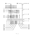
- Figure 3 shows four diagrams corresponding to four links pertaining to a path.
- Link 4 uses a 100 GHz grid.
- Link 3 uses a 50 GHz grid.
- Link 2 uses a 25 GHz grid.
- Link 1 uses a 12.5 GHz grid.
- the order of grids in a path does not matter. Said different grids are all aligned in that they share wavelength 20 corresponding respectively to wavelength 21, 23 and 25.
- the narrowest channel spaced grid in the network is supposed to be a 12.5 GHz, and said 12.5 GHz grid 1 is used to define the granularity and the canvas of weights.
- the widest channel spaced grid in the network is supposed to be a 100 GHz, and the weight for any central wavelength is determined depending on the distance to a wavelength 20, 20' present in said 100 GHz grid 4.
- central wavelengths 25 and 33 are aligned with central wavelengths 20, 20' of the 100 GHz grid and thus receive the maximum weight value.
- Central wavelength 29 is the farthest wavelength from said central wavelengths 20, 20' of the 100 GHz grid and thus receive the minimum weight value, although a positive value.
- Intermediary central wavelengths 28, 27, 26 are respectively second, third and fourth farthest wavelength from said central wavelengths 20, 20' and thus receive increasing weights in between minimum weight value and maximum weight value.
- central wavelength 23 is aligned with central wavelength 20 of the 100 GHz grid and thus receive the maximum weight value.
- Central wavelength 24 corresponds with central wavelength 27 of the weighting grid 1 and receives the same weight.
- central wavelength 21 is aligned with central wavelength 20 of the 100 GHz grid and thus receive the maximum weight value.
- Central wavelength 22 corresponds with central wavelength 29 of the weighting grid 1 and receives the same weight, that is, the minimum value, since 29 is also the farthest from being aligned central wavelength.
- aligned wavelengths are preferred. However it may occur that a non aligned wavelength is selected and assigned to a signal. Once a central wavelength not aligned with widest channel spaced grid has been assigned to a signal at least one corresponding channel of the widest spacing may no longer be used. In order not to waste too much bandwidth in that particular case a bonus value may be used for compensating. In order to take this case into account a bonus positive value may be added to the weight. When a central wavelength is neighbouring an occupied central wavelength not aligned with said widest channel spaced grid 4, then the weight of said central wavelength is augmented by the bonus value.
- the bonus value is taken inferior to the smallest difference between any two weight values. So doing the corrective effect of the bonus is such that its influence is lesser than the effect of a neighbouring with a widest channel spaced grid.
- a minimum value of 2 may be chosen. Said minimum value is affected to central wavelength farthest from being aligned with said widest channel spaced grid 4.
- a maximum value of 2 ⁇ (N-1)+2 may be affected to central wavelength aligned with said widest channel spaced grid 4, where N is the number of different channel spaced grids in the network, and ⁇ is the power operator.
- N 2
- N 2
- a central wavelength is either aligned and receives a weight of 4, or a central wavelength is not aligned (and is farthest from being aligned) and receives a weight of 2.
- N 4
- the maximum value is 10, and there are five levels of neighbourhood.
- a central wavelength aligned 25, 33 receives a weight of 10.
- a central wavelength 29 farthest from being aligned receives a weight of 2.
- a central wavelength 28, 30 second farthest from being aligned receives a weight of 4.
- a central wavelength 27, 31 third farthest from being aligned receives a weight of 6.
- a central wavelength 26, 32 fourth farthest from being aligned receives a weight of 8. So, each level of neighbourhood adds +2 to the weight, until reaching the maximum value of 2 ⁇ (N-1)+2 when the central wavelength is aligned with said widest channel spaced grid 4.
- the weight is a decreasing function of the distance to alignment.
- the general formula is thus a value of weight of 2 ⁇ (k-1)+2 assigned to the kth farthest from being aligned central wavelength 28, 30.
- the bonus value may then advantageously be chosen equal to 1.
- the allocated weights are figured facing their central wavelengths in frame 34.
- weights are determined according to the corresponding wavelength in said narrowest channel spaced grid 1.
- Central wavelength 21 of 50 GHz grid 3 is aligned and receives a weight of 10, equal to the weight of corresponding wavelength 25 in narrowest channel spaced grid 1.
- Central wavelength 22 of 50 GHz grid 3 receives a weight of 2, equal to the weight of corresponding wavelength 29 in grid 1.
- Central wavelength 23 of 25 GHz grid 2 is aligned and receives a weight of 10, equal to the weight of corresponding wavelength 25 in grid 1.
- Central wavelength 24 of 25 GHz grid 2 receives a weight of 6, equal to the weight of corresponding wavelength 27 in grid 1.
- a 50 GHz width signal 35 is supposed to have been assigned to central wavelength 24 in 25 GHz grid 2, which is not a wavelength aligned with the 100 GHz grid 4. So doing, at least one 100 GHz channel is occupied. In order not to waste too much bandwidth, since the 100 GHz channel is already used, the remaining parts of said partly used 100 GHz channel are allocated a bonus value. Thus, a bonus value is added to central wavelengths 36, 37 neighbouring the occupied wavelength 24. The new weights so determined for the 25 GHz grid 2 are figured in frame 38. Former weights of 6 for said wavelengths 36 and 37 are now 7, since a bonus of 1 has been added. In addition, the weights of all occupied channels have been turned to 0.
- the bonus mechanism is now applied to 12,5 GHz grid 1.
- a combine operator may be defined by: the combination of two non zero weights is equal to their sum, and the combination of two weights whose at least one equal zero is equal to zero. Said combine operator is thus a sort of sum operator, but with an absorbing element being zero. Multiplication could also equivalently be used. So doing, for a path, with a resolution of the narrowest spaced grid, each central wavelength is assigned a combined weight. Due to the effect of 0, as soon as a wavelength is used, at least partially in only one link, its combined weight becomes 0 and it then have no chance of being assigned.
- a central wavelength receives a combined weight resulting from the sum of all the weights allocated to said central wavelength along the path indicative of the neighbouring of said central wavelength to a wavelength of the widest channel spaced grid 4, including if it applies, some bonus.
- the combined allocated weights for the previous example are shown facing their central wavelengths in frame 39.
- an optimal combined weight may be determined in order to assign a signal to a wavelength of optimal weight. If several equal optimal weights can be determined, one of them is randomly selected.
- the optimal combined weight is always the maximum of combined weights.
- the optimal combined weight is the maximum of combined weights only if at least one link crossed by the path uses a widest channel spaced grid 4. And if no widest channel spaced grid can be found along the path, since there is no use to align over such a widest channel spaced grid 4, an optimal wavelength may be chosen instead as the minimum of non zero combined weights.
- Signal to be assigned generally arrive on the fly to be assigned. However, if the case occurs of several signals arriving at the same time, according to a preferred embodiment, they are assigned a wavelength starting by the widest signals, and then proceeding with the narrower signals.
Landscapes
- Engineering & Computer Science (AREA)
- Computer Networks & Wireless Communication (AREA)
- Signal Processing (AREA)
- Physics & Mathematics (AREA)
- Electromagnetism (AREA)
- Optical Communication System (AREA)
Abstract
- determining, through the network, the widest channel spaced grid (4) and the narrowest channel spaced grid (1);
- parting, at each link (1, 2, 3, 4) through said path, the total optical bandwidth into central wavelengths spaced and aligned with the narrowest channel spaced grid (1);
- weighting, at each link (1, 2, 3, 4) through said path, each central wavelength with a weight indicative of the occupation of said central wavelength at said link and of the alignment of said central wavelength with said widest channel spaced grid (4);
- combining, the weights encountered through said path for each central wavelength; and
- assigning said signal to be routed to a central wavelength with an optimal combined weight.
Description
- The technical domain of the invention is the domain of communication networks, and particularly transparent optical networks.
- More particularly, the invention concerns a method to optimally assign a signal to a central wavelength in an optical network, in presence of optical grids of different channel spacing.
- To transmit information, an optical network usually employs optical fibre as a transport link between two nodes. Over such an optical fibre, in systems such as Wavelength Division Multiplexing, WDM, total bandwidth is parted into channels of equal width and consequently of equal spacing. Each channel may also be referred to by its central wavelength. Such partition or comb is also referred to as a grid. Initially used grids were of 100 GHz spaced channels.
- The improvement of transparent transport performance has enabled the reduction of the channel spacing in the optical comb, decreasing from 100 GHz to 50 GHz. Furthermore, thanks to new filtering technologies channel spacing could be further reduced down to 25 GHz or 12,5 GHz. Each channel spacing corresponds to a wavelength grid.
- In a transparent network, different grids may coexist due to the presence of filter devices with different characteristics in nodes, for instance various generations of wavelength selective switches, WSS. However, each link uses a single grid.
- However, the presence of optical grids with different channel spacing may create fragmentation. Wavelength continuity between successive adjacent links is not guaranteed as with uniform channel spacing. Former usual routing strategies may lead to significant stranding (under-utilization) of bandwidth.
- Recent WSS have been developed so as to exhibit a flat filtering function over the wavebands they are switching, i.e. as weak as possible amplitude and phase ripple between channels of a same waveband.
- The object of the present invention is a solution to minimize the waste of bandwidth in mixed-grid transparent networks.
- The object of the invention is a method of assigning a signal to a central wavelength through a path crossing successive links in a transparent optical network comprising nodes connected by a plurality of links, each link using an optical grid parting the total optical bandwidth into central wavelengths defining channels of equal width, with a constant channel spacing, the optical grids of the plurality of links being aligned, the method comprising the steps of:
- determining, through the network, the widest channel spaced grid and the narrowest channel spaced grid;
- parting, at each link through said path, the total optical bandwidth into central wavelengths spaced and aligned with the narrowest channel spaced grid;
- weighting, at each link through said path, each central wavelength with a weight indicative of the occupation of said central wavelength at said link and of the alignment of said central wavelength with said widest channel spaced grid;
- combining, the weights encountered through said path for each central wavelength; and
- assigning said signal to be routed to a central wavelength with an optimal combined weight.
- According to another feature of the invention, the weight of a central wavelength is 0 when the central wavelength is occupied, and otherwise the weight is a value chosen between a minimum strictly positive value and a maximum strictly positive value as a decreasing function of the distance between said central wavelength and a nearest central wavelength aligned with said widest channel spaced grid.
- According to another feature of the invention, the weight is augmented by a positive bonus value when a central wavelength is neighbouring an occupied central wavelength not aligned with said widest channel spaced grid.
- According to another feature of the invention said bonus value is lesser than the smallest difference between any two weight values.
- According to another feature of the invention, the weight of a central wavelength is equal to:
- a value of 0 when the central wavelength is occupied;
- a minimum value of 2 when the central wavelength is farthest from being aligned with said widest channel spaced grid;
- a value of 4 when the central wavelength is second farthest from being aligned with said widest channel spaced grid, if that case occurs;
- a value of 2^(k-1)+2, 3<=k<=N, when the central wavelength is kth farthest from being aligned with said widest channel spaced grid, if that case occurs;
- until reaching the maximum value of 2^ (N-1)+2 when the central wavelength is aligned with said widest channel spaced grid, where N is the number of different channel spaced grids in the network,
- According to another feature of the invention, said combine step uses an operator defined by:
- the combination of two non zero weights is equal to their sum,
- the combination of two weights is equal to zero, when at least one of them is equal to zero.
- According to another feature of the invention, the optimal combined weight is:
- the maximum of combined weights if at least one link crossed by the path uses a widest channel spaced grid, and
- the minimum of non zero combined weights if none of the links crossed by the path uses a widest channel spaced grid.
- According to another feature of the invention, when several signals of different width have to be assigned, the widest signal is assigned first.
- The invention also concerns a system able to implement the aforementioned method.
- Others features, details and advantages of the invention will become more apparent from the detailed illustrating description given hereafter with respect to the drawings on which:
-
figure 1 is a diagram showing three different grids and their alignment, -
figure 2 is a diagram showing two 50 GHz signals routed and the resulting wastes of bandwidth, -
figure 3 is a diagram illustrating a path comprising four different grids and the principles of weighting, -
figure 4 is a diagram illustrating bonus and combining of weights. - The invention takes place in a transparent optical network. Such a network comprises nodes. Said nodes are connected by links comprising optical fibre. For each such link a grid is defined by either the source node or the destination node or both in conjunction, according to their respective characteristics.
- As illustrated on
figure 1 , agrid constant channel width 8 or equivalently by a constant channel spacing 7 or equivalently by aconstant spacing 7 between adjacentcentral wavelengths 5. Said different spacings are multiple, and e.g. power of two multiple, from one grid to another. Infigure 1 ,reference 2 is a 25 GHz grid, 3 is a 50 GHz grid and 4 is a 100 GHz grid. Typical spacings are taken among 100 GHz, 50 GHz, 25 GHz and 12,5 GHz. Moreover saidgrids central wavelength 9 of a channel of a wider spacedgrid 4 always corresponds to acentral wavelength 9 of a channel of a narrower spacedgrid central wavelength 9 defined in a wider channel spacedgrid 4, is exactly matched by a correspondingcentral wavelength 9 in a narrower channel spaced grid. - When a signal is routed, it must be assigned to a
central wavelength 5 across several links forming a path. An optical signal is modulated on top of a carrier whosewavelength 5 is set at the centre of a chosenchannel 6, that is, thecentral wavelength 5 of saidchannel 6. An occupied channel in a 50 GHz grid therefore blocks +/- 25 GHz on both sides of its central wavelength. Similarly achannel 6 in a 100 GHz grid starts at -50 GHz and finishes at +50 GHz with respect to the selectedcentral wavelength 5. - Once a central wavelength/channel is chosen it must be the same along the whole path. No overlap in wavelengths is allowed, and when a central wavelength/channel is assigned to a signal in presence of links with different channel spacing, the chosen channel may lead to a waste in bandwidth.
- With reference to
figure 2 the assignment of a e.g. 50GHz signal 10, in a 50GHz grid 3, to acentral wavelength 11 aligned with the 100GHz grid 4, that is corresponding tocentral wavelength 12, occupies one 100GHz channel 13, that is, 100 GHz in bandwidth. Although the assignment of another 50GHz signal 14 to acentral wavelength 15 not aligned with the 100GHz grid 4, (not aligned with eitherwavelength 18 or 19), may occupy two 100GHz channels GHz grid 4. - The present invention concerns a method to optimize the use of bandwidth in the case of mixed channel spacing, that is, different grids along a routing path.
- Several grids may be found/used in a given optical network. The number of grids may be any number greater than or equal to two, among a set of power of two multiple channel spacing grids. For instance an optical network may comprise any at least two differently spaced grids among the illustrative set of 12,5 GHz, 25 GHz, 50 GHz and 100 GHz grids.
- The method starts with a first step of determining, through the network, the widest channel spaced
grid 4 and the narrowest channel spacedgrid 1, since the corresponding widest and narrowest spacings govern the method. As will be explained later these widest and narrowest spacings may not necessarily be the widest and narrowest spacings encountered along the routing path considered, since not all the grids present in the network are present in the path. - In a second step, at each link through the path, the total optical bandwidth is parted into central wavelengths spaced and aligned with the central wavelengths of said narrowest channel spaced
grid 1. - E.g., if 25 GHz and 100 GHz grids are present in the optical network, a 25GHz aligned grid, corresponding to the narrowest spacing, is used to provide a supporting canvas to weight central wavelengths.
- In a third step, each such central wavelength is then weighted with a weight value. Said weight is indicative of the occupation of said central wavelength at said link and of the alignment of said central wavelength with the widest channel spaced grid.
- In a fourth step, along the path associated to the signal to route, central wavelength by central wavelength, the weights are combined to determine combined weights.
- In a fifth step, the signal to be routed is assigned to a central wavelength with an optimal combined weight.
- In the following will be explained the way of weighting central wavelengths. A weight of zero is allocated to an already assigned central wavelength, that is, to any central wavelength occupied. So doing, and in combination of the particular use of said zero value in combining weights, an occupied central wavelength has no chance to be assigned to a signal.
- In order to keep channels free in the links using widest channel spacing grids, central wavelengths aligned with the wavelengths of said widest channel spacing grid are preferred and given the maximum weight.
- If a central wavelength is free, the weight allocated is a non zero value. Said weight value is indicative of the (quality of the) alignment of said central wavelength with the widest channel spaced
grid 4. Said weight value may be chosen between a minimum strictly positive value and a maximum strictly positive value and may be allocated as a decreasing function of the distance between said central wavelength and a nearest central wavelength aligned with said widest channel spacedgrid 4. - This is better explained with reference to an example as illustrated in
figure 3. Figure 3 shows four diagrams corresponding to four links pertaining to a path.Link 4 uses a 100 GHz grid.Link 3 uses a 50 GHz grid.Link 2 uses a 25 GHz grid.Link 1 uses a 12.5 GHz grid. The order of grids in a path does not matter. Said different grids are all aligned in that they sharewavelength 20 corresponding respectively towavelength GHz grid 1 is used to define the granularity and the canvas of weights. The widest channel spaced grid in the network is supposed to be a 100 GHz, and the weight for any central wavelength is determined depending on the distance to awavelength 20, 20' present in said 100GHz grid 4. - When considering the 12.5
GHz grid 1,central wavelengths central wavelengths 20, 20' of the 100 GHz grid and thus receive the maximum weight value.Central wavelength 29 is the farthest wavelength from saidcentral wavelengths 20, 20' of the 100 GHz grid and thus receive the minimum weight value, although a positive value. Intermediarycentral wavelengths central wavelengths 20, 20' and thus receive increasing weights in between minimum weight value and maximum weight value. - When considering the 25
GHz grid 2,central wavelength 23 is aligned withcentral wavelength 20 of the 100 GHz grid and thus receive the maximum weight value.Central wavelength 24 corresponds withcentral wavelength 27 of theweighting grid 1 and receives the same weight. - When considering the 50
GHz grid 3,central wavelength 21 is aligned withcentral wavelength 20 of the 100 GHz grid and thus receive the maximum weight value. Central wavelength 22 corresponds withcentral wavelength 29 of theweighting grid 1 and receives the same weight, that is, the minimum value, since 29 is also the farthest from being aligned central wavelength. - By doing so aligned wavelengths are preferred. However it may occur that a non aligned wavelength is selected and assigned to a signal. Once a central wavelength not aligned with widest channel spaced grid has been assigned to a signal at least one corresponding channel of the widest spacing may no longer be used. In order not to waste too much bandwidth in that particular case a bonus value may be used for compensating. In order to take this case into account a bonus positive value may be added to the weight. When a central wavelength is neighbouring an occupied central wavelength not aligned with said widest channel spaced
grid 4, then the weight of said central wavelength is augmented by the bonus value. - In a preferred embodiment, the bonus value is taken inferior to the smallest difference between any two weight values. So doing the corrective effect of the bonus is such that its influence is lesser than the effect of a neighbouring with a widest channel spaced grid.
- As an example of an embodiment, illustrated on
figures 3 and4 , a minimum value of 2 may be chosen. Said minimum value is affected to central wavelength farthest from being aligned with said widest channel spacedgrid 4. On the other end, a maximum value of 2^(N-1)+2 may be affected to central wavelength aligned with said widest channel spacedgrid 4, where N is the number of different channel spaced grids in the network, and ^ is the power operator. - With N = 2, the maximum value is 4, and they are only two levels of neighbourhood. A central wavelength is either aligned and receives a weight of 4, or a central wavelength is not aligned (and is farthest from being aligned) and receives a weight of 2.
- With N = 4, as illustrated in
figure 3 and4 , the maximum value is 10, and there are five levels of neighbourhood. A central wavelength aligned 25, 33, receives a weight of 10. Acentral wavelength 29 farthest from being aligned receives a weight of 2. Acentral wavelength central wavelength central wavelength grid 4. The weight is a decreasing function of the distance to alignment. The general formula is thus a value of weight of 2^(k-1)+2 assigned to the kth farthest from being alignedcentral wavelength - So doing the difference between the weight values of any two adjacent levels of neighbourhood is 2. The bonus value may then advantageously be chosen equal to 1. The allocated weights are figured facing their central wavelengths in
frame 34. - For intermediary spaced
grids grid 1.Central wavelength 21 of 50GHz grid 3 is aligned and receives a weight of 10, equal to the weight of correspondingwavelength 25 in narrowest channel spacedgrid 1. Central wavelength 22 of 50GHz grid 3 receives a weight of 2, equal to the weight of correspondingwavelength 29 ingrid 1.Central wavelength 23 of 25GHz grid 2 is aligned and receives a weight of 10, equal to the weight of correspondingwavelength 25 ingrid 1.Central wavelength 24 of 25GHz grid 2 receives a weight of 6, equal to the weight of correspondingwavelength 27 ingrid 1. - Now referring to
figure 4 , will be explained the bonus allocation mechanism. A 50GHz width signal 35 is supposed to have been assigned tocentral wavelength 24 in 25GHz grid 2, which is not a wavelength aligned with the 100GHz grid 4. So doing, at least one 100 GHz channel is occupied. In order not to waste too much bandwidth, since the 100 GHz channel is already used, the remaining parts of said partly used 100 GHz channel are allocated a bonus value. Thus, a bonus value is added tocentral wavelengths wavelength 24. The new weights so determined for the 25GHz grid 2 are figured inframe 38. Former weights of 6 for saidwavelengths - Still referring to
figure 4 , the bonus mechanism is now applied to 12,5GHz grid 1. On saidgrid 1, onlycentral wavelength 28 is occupied. Since it is a non aligned central wavelength, both itsneighbours - When all links in a path have been weighted, the weights can be combined, wavelength by wavelength, along said path. A combine operator may be defined by: the combination of two non zero weights is equal to their sum, and the combination of two weights whose at least one equal zero is equal to zero. Said combine operator is thus a sort of sum operator, but with an absorbing element being zero. Multiplication could also equivalently be used. So doing, for a path, with a resolution of the narrowest spaced grid, each central wavelength is assigned a combined weight. Due to the effect of 0, as soon as a wavelength is used, at least partially in only one link, its combined weight becomes 0 and it then have no chance of being assigned. Otherwise, if a central wavelength is free along the whole path, it receives a combined weight resulting from the sum of all the weights allocated to said central wavelength along the path indicative of the neighbouring of said central wavelength to a wavelength of the widest channel spaced
grid 4, including if it applies, some bonus. - The combined allocated weights for the previous example are shown facing their central wavelengths in
frame 39. - Based on these combined weights, an optimal combined weight may be determined in order to assign a signal to a wavelength of optimal weight. If several equal optimal weights can be determined, one of them is randomly selected.
- According to a first strategy, the optimal combined weight is always the maximum of combined weights.
- According to a second strategy, the optimal combined weight is the maximum of combined weights only if at least one link crossed by the path uses a widest channel spaced
grid 4. And if no widest channel spaced grid can be found along the path, since there is no use to align over such a widest channel spacedgrid 4, an optimal wavelength may be chosen instead as the minimum of non zero combined weights. - Signal to be assigned generally arrive on the fly to be assigned. However, if the case occurs of several signals arriving at the same time, according to a preferred embodiment, they are assigned a wavelength starting by the widest signals, and then proceeding with the narrower signals.
Claims (10)
- A method of assigning a signal (10) to a central wavelength (5) through a path crossing successive links (1, 2, 3, 4) in a transparent optical network comprising nodes connected by a plurality of links, each link (1, 2, 3, 4) using an optical grid parting the total optical bandwidth into central wavelengths (5) defining channels (6) of equal width (8), with a constant channel spacing (7), the optical grids of the plurality of links being aligned, the method being characterized in that it comprises the steps of:- determining, through the network, the widest channel spaced grid (4) and the narrowest channel spaced grid (1);- parting, at each link (1, 2, 3, 4) through said path, the total optical bandwidth into central wavelengths (5) spaced and aligned with the narrowest channel spaced grid (1);- weighting, at each link (1, 2, 3, 4) through said path, each central wavelength (5) with a weight indicative of the occupation of said central wavelength (5) at said link and of the alignment of said central wavelength (5) with said widest channel spaced grid (4);- combining, the weights encountered through said path for each central wavelength (5); and- assigning said signal (10) to be routed to a central wavelength (5) with an optimal combined weight.
- The method of claim 1, wherein the weight of a central wavelength (21-33) is 0 when the central wavelength is occupied, and otherwise the weight is a value chosen between a minimum strictly positive value and a maximum strictly positive value as a decreasing function of the distance between said central wavelength (21-33) and a nearest central wavelength (20, 20') aligned with said widest channel spaced grid (4).
- The method of claim 1 or 2, wherein the weight is augmented by a positive bonus value when a central wavelength (21-33) is neighbouring an occupied central wavelength not aligned with said widest channel spaced grid (4).
- The method of claim 3, wherein said bonus value is lesser than the smallest difference between any two weight values.
- The method of any one of claims 1 to 4, wherein the weight of a central wavelength (21-33) is equal to:- a value of 0 when the central wavelength (21-33) is occupied;- a minimum value of 2 when the central wavelength (22, 29) is farthest from being aligned with said widest channel spaced grid (4);- a value of 4 when the central wavelength (28, 30) is second farthest from being aligned with said widest channel spaced grid (4), if that case occurs;- a value of 2^(k-1)+2, 3<=k<=N, when the central wavelength (28, 30) is kth farthest from being aligned with said widest channel spaced grid (4), if that case occurs;- until reaching the maximum value of 2^(N-1)+2 when the central wavelength (21, 23, 25, 33) is aligned with said widest channel spaced grid (4), where N is the number of different channel spaced grids (1, 2, 3, 4) in the network,and wherein the bonus value is +1.
- The method of any one of claims 1 to 5, wherein said combine step uses an operator defined by:- the combination of two non zero weights is equal to their sum,- the combination of two weights is equal to zero, when at least one of them is equal to zero.
- The method of any one of claims 1 to 6, wherein the optimal combined weight is:- the maximum of combined weights if at least one link (1, 2, 3, 4) crossed by the path uses a widest channel spaced grid (4), and- the minimum of non zero combined weights if none of the links (1, 2, 3, 4) crossed by the path uses a widest channel spaced grid (4).
- The method of any one of claims 1 to 7, wherein when several signals (10) of different width are to be assigned, the widest signal is assigned first.
- A system to assign a signal (10) to a central wavelength (5) through a path crossing successive links (1, 2, 3, 4) in a transparent optical network comprising nodes connected by a plurality of links, each link (1, 2, 3, 4) using an optical grid parting the total optical bandwidth into central wavelengths (5) defining channels (6) of equal width (8), with a constant channel spacing (7), the optical grids of the plurality of links being aligned, the system being characterized in that it comprises:- determining means arranged to determine, through the network, the widest channel spaced grid (4) and the narrowest channel spaced grid (1);- parting means arranged to part, at each link (1, 2, 3, 4) through said path, the total optical bandwidth into central wavelengths (5) spaced and aligned with the narrowest channel spaced grid (1);- weighting means arranged to weigh, at each link (1, 2, 3, 4) through said path, each central wavelength (5) with a weight indicative of the occupation of said central wavelength (5) at said link and of the alignment of said central wavelength (5) with said widest channel spaced grid (4);- combining means arranged to combine, the weights encountered through said path for each central wavelength (5); and- assigning means arranged to assign said signal (10) to be routed to a central wavelength (5) with an optimal combined weight.
- The system of claim 9, further comprising weight computing means arranged to compute weights according to the method of any one of claims 2 to 7.
Priority Applications (1)
| Application Number | Priority Date | Filing Date | Title |
|---|---|---|---|
| EP10306243.6A EP2453603B1 (en) | 2010-11-10 | 2010-11-10 | A method to assign a signal in a transparent optical network using multiple channel spaced grids |
Applications Claiming Priority (1)
| Application Number | Priority Date | Filing Date | Title |
|---|---|---|---|
| EP10306243.6A EP2453603B1 (en) | 2010-11-10 | 2010-11-10 | A method to assign a signal in a transparent optical network using multiple channel spaced grids |
Publications (2)
| Publication Number | Publication Date |
|---|---|
| EP2453603A1 true EP2453603A1 (en) | 2012-05-16 |
| EP2453603B1 EP2453603B1 (en) | 2014-07-30 |
Family
ID=43733886
Family Applications (1)
| Application Number | Title | Priority Date | Filing Date |
|---|---|---|---|
| EP10306243.6A Active EP2453603B1 (en) | 2010-11-10 | 2010-11-10 | A method to assign a signal in a transparent optical network using multiple channel spaced grids |
Country Status (1)
| Country | Link |
|---|---|
| EP (1) | EP2453603B1 (en) |
Families Citing this family (1)
| Publication number | Priority date | Publication date | Assignee | Title |
|---|---|---|---|---|
| CN111010627B (en) * | 2019-11-25 | 2021-04-20 | 北京邮电大学 | Route distribution method and device applied to hybrid grid optical network |
Citations (4)
| Publication number | Priority date | Publication date | Assignee | Title |
|---|---|---|---|---|
| WO2001039380A2 (en) * | 1999-10-01 | 2001-05-31 | New Focus, Inc. | Otpical mux/demux |
| US20010013962A1 (en) * | 1997-09-02 | 2001-08-16 | Yuan P. Li | Method and apparatus for wavelength-channel tracking and alignment within an optical communications system |
| US20030072052A1 (en) * | 2001-10-10 | 2003-04-17 | Graves Alan F. | Optical wavelength plan for metropolitan photonic network |
| WO2004109958A1 (en) * | 2003-06-10 | 2004-12-16 | Nortel Networks Limited | Flexible banded mux/demux architecture for wdm systems |
-
2010
- 2010-11-10 EP EP10306243.6A patent/EP2453603B1/en active Active
Patent Citations (4)
| Publication number | Priority date | Publication date | Assignee | Title |
|---|---|---|---|---|
| US20010013962A1 (en) * | 1997-09-02 | 2001-08-16 | Yuan P. Li | Method and apparatus for wavelength-channel tracking and alignment within an optical communications system |
| WO2001039380A2 (en) * | 1999-10-01 | 2001-05-31 | New Focus, Inc. | Otpical mux/demux |
| US20030072052A1 (en) * | 2001-10-10 | 2003-04-17 | Graves Alan F. | Optical wavelength plan for metropolitan photonic network |
| WO2004109958A1 (en) * | 2003-06-10 | 2004-12-16 | Nortel Networks Limited | Flexible banded mux/demux architecture for wdm systems |
Also Published As
| Publication number | Publication date |
|---|---|
| EP2453603B1 (en) | 2014-07-30 |
Similar Documents
| Publication | Publication Date | Title |
|---|---|---|
| US8909043B2 (en) | Routing, wavelength assignment, and spectrum allocation in wavelength convertible flexible optical wavelength-division multiplexing networks | |
| US9654248B2 (en) | Optical data transmission method and apparatus | |
| KR101542758B1 (en) | Allocation of spectral capacity in a wavelength-division multiplexing optical network | |
| Eira et al. | On the impact of optimized guard-band assignment for superchannels in flexible-grid optical networks | |
| Fadini et al. | A subcarrier-slot partition scheme for wavelength assignment in elastic optical networks | |
| US20090047019A1 (en) | Method and System for Communicating Optical Traffic | |
| Rumipamba-Zambrano et al. | Space continuity constraint in dynamic flex-grid/SDM optical core networks: an evaluation with spatial and spectral super-channels | |
| CN107005336B (en) | Hybrid Optical Switch for Software-Defined Networking | |
| JP7400877B2 (en) | Optical network management equipment and optical band allocation method | |
| Dharmaweera et al. | Nonlinear-impairments-and crosstalk-aware resource allocation schemes for multicore-fiber-based flexgrid networks | |
| Wang et al. | Efficient all-optical wavelength converter placement and wavelength assignment in optical networks | |
| US10382135B2 (en) | Optical node device, optical network controller, and optical network control method | |
| Shen et al. | Maximizing time-dependent spectrum sharing between neighbouring channels in CO-OFDM optical networks | |
| EP2453603B1 (en) | A method to assign a signal in a transparent optical network using multiple channel spaced grids | |
| WO2018056285A1 (en) | Optical path design device and optical path design method | |
| CN106060682B (en) | Band Routing Method Based on Serial Structure Hierarchical Optical Cross-connect | |
| Anchal et al. | Practical SDM-ROADM designs for uncoupled spatial channels and their switching capacity | |
| Lohani et al. | Dynamic Routing, Waveband, and Spectrum Assignment for Optical Superchannels in IP over Multi-Granular Optical Nodes | |
| Shi et al. | Contaminated area-based RSCA algorithm for super-channel in flex-grid enabled SDM networks | |
| US9270376B2 (en) | Method of allocating bandwidth in an optical network | |
| Shariati et al. | Spectrally and spatially flexible optical networks: recent developments and findings | |
| US10231035B2 (en) | Optical network controller and optical network control method | |
| CN103650380B (en) | The crosstalk method and apparatus of cost of a kind of attenuating | |
| Mrad et al. | Adaptive-cost Shortest Path Based Heuristic for Space Division Multiplexing Networks | |
| Varma et al. | Spectrum and waveband assignment in elastic optical waveband networks |
Legal Events
| Date | Code | Title | Description |
|---|---|---|---|
| PUAI | Public reference made under article 153(3) epc to a published international application that has entered the european phase |
Free format text: ORIGINAL CODE: 0009012 |
|
| AK | Designated contracting states |
Kind code of ref document: A1 Designated state(s): AL AT BE BG CH CY CZ DE DK EE ES FI FR GB GR HR HU IE IS IT LI LT LU LV MC MK MT NL NO PL PT RO RS SE SI SK SM TR |
|
| AX | Request for extension of the european patent |
Extension state: BA ME |
|
| 17P | Request for examination filed |
Effective date: 20121116 |
|
| RIC1 | Information provided on ipc code assigned before grant |
Ipc: H04J 14/02 20060101AFI20130409BHEP |
|
| 111Z | Information provided on other rights and legal means of execution |
Free format text: AL AT BE BG CH CY CZ DE DK EE ES FI FR GB GR HR HU IE IS IT LI LT LU LV MC MK MT NL NO PL PT RO RS SE SI SK SM TR Effective date: 20130410 |
|
| GRAP | Despatch of communication of intention to grant a patent |
Free format text: ORIGINAL CODE: EPIDOSNIGR1 |
|
| INTG | Intention to grant announced |
Effective date: 20140218 |
|
| GRAS | Grant fee paid |
Free format text: ORIGINAL CODE: EPIDOSNIGR3 |
|
| GRAA | (expected) grant |
Free format text: ORIGINAL CODE: 0009210 |
|
| AK | Designated contracting states |
Kind code of ref document: B1 Designated state(s): AL AT BE BG CH CY CZ DE DK EE ES FI FR GB GR HR HU IE IS IT LI LT LU LV MC MK MT NL NO PL PT RO RS SE SI SK SM TR |
|
| REG | Reference to a national code |
Ref country code: GB Ref legal event code: FG4D |
|
| REG | Reference to a national code |
Ref country code: CH Ref legal event code: EP |
|
| REG | Reference to a national code |
Ref country code: AT Ref legal event code: REF Ref document number: 680388 Country of ref document: AT Kind code of ref document: T Effective date: 20140815 |
|
| RAP2 | Party data changed (patent owner data changed or rights of a patent transferred) |
Owner name: ALCATEL LUCENT |
|
| REG | Reference to a national code |
Ref country code: IE Ref legal event code: FG4D |
|
| REG | Reference to a national code |
Ref country code: DE Ref legal event code: R096 Ref document number: 602010017870 Country of ref document: DE Effective date: 20140911 |
|
| REG | Reference to a national code |
Ref country code: AT Ref legal event code: MK05 Ref document number: 680388 Country of ref document: AT Kind code of ref document: T Effective date: 20140730 |
|
| REG | Reference to a national code |
Ref country code: NL Ref legal event code: VDEP Effective date: 20140730 |
|
| REG | Reference to a national code |
Ref country code: LT Ref legal event code: MG4D |
|
| PG25 | Lapsed in a contracting state [announced via postgrant information from national office to epo] |
Ref country code: FI Free format text: LAPSE BECAUSE OF FAILURE TO SUBMIT A TRANSLATION OF THE DESCRIPTION OR TO PAY THE FEE WITHIN THE PRESCRIBED TIME-LIMIT Effective date: 20140730 Ref country code: ES Free format text: LAPSE BECAUSE OF FAILURE TO SUBMIT A TRANSLATION OF THE DESCRIPTION OR TO PAY THE FEE WITHIN THE PRESCRIBED TIME-LIMIT Effective date: 20140730 Ref country code: LT Free format text: LAPSE BECAUSE OF FAILURE TO SUBMIT A TRANSLATION OF THE DESCRIPTION OR TO PAY THE FEE WITHIN THE PRESCRIBED TIME-LIMIT Effective date: 20140730 Ref country code: SE Free format text: LAPSE BECAUSE OF FAILURE TO SUBMIT A TRANSLATION OF THE DESCRIPTION OR TO PAY THE FEE WITHIN THE PRESCRIBED TIME-LIMIT Effective date: 20140730 Ref country code: PT Free format text: LAPSE BECAUSE OF FAILURE TO SUBMIT A TRANSLATION OF THE DESCRIPTION OR TO PAY THE FEE WITHIN THE PRESCRIBED TIME-LIMIT Effective date: 20141202 Ref country code: NO Free format text: LAPSE BECAUSE OF FAILURE TO SUBMIT A TRANSLATION OF THE DESCRIPTION OR TO PAY THE FEE WITHIN THE PRESCRIBED TIME-LIMIT Effective date: 20141030 Ref country code: BG Free format text: LAPSE BECAUSE OF FAILURE TO SUBMIT A TRANSLATION OF THE DESCRIPTION OR TO PAY THE FEE WITHIN THE PRESCRIBED TIME-LIMIT Effective date: 20141030 Ref country code: GR Free format text: LAPSE BECAUSE OF FAILURE TO SUBMIT A TRANSLATION OF THE DESCRIPTION OR TO PAY THE FEE WITHIN THE PRESCRIBED TIME-LIMIT Effective date: 20141031 |
|
| PG25 | Lapsed in a contracting state [announced via postgrant information from national office to epo] |
Ref country code: PL Free format text: LAPSE BECAUSE OF FAILURE TO SUBMIT A TRANSLATION OF THE DESCRIPTION OR TO PAY THE FEE WITHIN THE PRESCRIBED TIME-LIMIT Effective date: 20140730 Ref country code: RS Free format text: LAPSE BECAUSE OF FAILURE TO SUBMIT A TRANSLATION OF THE DESCRIPTION OR TO PAY THE FEE WITHIN THE PRESCRIBED TIME-LIMIT Effective date: 20140730 Ref country code: LV Free format text: LAPSE BECAUSE OF FAILURE TO SUBMIT A TRANSLATION OF THE DESCRIPTION OR TO PAY THE FEE WITHIN THE PRESCRIBED TIME-LIMIT Effective date: 20140730 Ref country code: HR Free format text: LAPSE BECAUSE OF FAILURE TO SUBMIT A TRANSLATION OF THE DESCRIPTION OR TO PAY THE FEE WITHIN THE PRESCRIBED TIME-LIMIT Effective date: 20140730 Ref country code: NL Free format text: LAPSE BECAUSE OF FAILURE TO SUBMIT A TRANSLATION OF THE DESCRIPTION OR TO PAY THE FEE WITHIN THE PRESCRIBED TIME-LIMIT Effective date: 20140730 Ref country code: AT Free format text: LAPSE BECAUSE OF FAILURE TO SUBMIT A TRANSLATION OF THE DESCRIPTION OR TO PAY THE FEE WITHIN THE PRESCRIBED TIME-LIMIT Effective date: 20140730 Ref country code: IS Free format text: LAPSE BECAUSE OF FAILURE TO SUBMIT A TRANSLATION OF THE DESCRIPTION OR TO PAY THE FEE WITHIN THE PRESCRIBED TIME-LIMIT Effective date: 20141130 Ref country code: CY Free format text: LAPSE BECAUSE OF FAILURE TO SUBMIT A TRANSLATION OF THE DESCRIPTION OR TO PAY THE FEE WITHIN THE PRESCRIBED TIME-LIMIT Effective date: 20140730 |
|
| PG25 | Lapsed in a contracting state [announced via postgrant information from national office to epo] |
Ref country code: SK Free format text: LAPSE BECAUSE OF FAILURE TO SUBMIT A TRANSLATION OF THE DESCRIPTION OR TO PAY THE FEE WITHIN THE PRESCRIBED TIME-LIMIT Effective date: 20140730 Ref country code: DK Free format text: LAPSE BECAUSE OF FAILURE TO SUBMIT A TRANSLATION OF THE DESCRIPTION OR TO PAY THE FEE WITHIN THE PRESCRIBED TIME-LIMIT Effective date: 20140730 Ref country code: EE Free format text: LAPSE BECAUSE OF FAILURE TO SUBMIT A TRANSLATION OF THE DESCRIPTION OR TO PAY THE FEE WITHIN THE PRESCRIBED TIME-LIMIT Effective date: 20140730 Ref country code: IT Free format text: LAPSE BECAUSE OF FAILURE TO SUBMIT A TRANSLATION OF THE DESCRIPTION OR TO PAY THE FEE WITHIN THE PRESCRIBED TIME-LIMIT Effective date: 20140730 Ref country code: CZ Free format text: LAPSE BECAUSE OF FAILURE TO SUBMIT A TRANSLATION OF THE DESCRIPTION OR TO PAY THE FEE WITHIN THE PRESCRIBED TIME-LIMIT Effective date: 20140730 Ref country code: RO Free format text: LAPSE BECAUSE OF FAILURE TO SUBMIT A TRANSLATION OF THE DESCRIPTION OR TO PAY THE FEE WITHIN THE PRESCRIBED TIME-LIMIT Effective date: 20140730 |
|
| REG | Reference to a national code |
Ref country code: DE Ref legal event code: R097 Ref document number: 602010017870 Country of ref document: DE |
|
| PLBE | No opposition filed within time limit |
Free format text: ORIGINAL CODE: 0009261 |
|
| STAA | Information on the status of an ep patent application or granted ep patent |
Free format text: STATUS: NO OPPOSITION FILED WITHIN TIME LIMIT |
|
| PG25 | Lapsed in a contracting state [announced via postgrant information from national office to epo] |
Ref country code: BE Free format text: LAPSE BECAUSE OF NON-PAYMENT OF DUE FEES Effective date: 20141130 Ref country code: LU Free format text: LAPSE BECAUSE OF FAILURE TO SUBMIT A TRANSLATION OF THE DESCRIPTION OR TO PAY THE FEE WITHIN THE PRESCRIBED TIME-LIMIT Effective date: 20141110 Ref country code: MC Free format text: LAPSE BECAUSE OF FAILURE TO SUBMIT A TRANSLATION OF THE DESCRIPTION OR TO PAY THE FEE WITHIN THE PRESCRIBED TIME-LIMIT Effective date: 20140730 |
|
| REG | Reference to a national code |
Ref country code: CH Ref legal event code: PL |
|
| 26N | No opposition filed |
Effective date: 20150504 |
|
| PG25 | Lapsed in a contracting state [announced via postgrant information from national office to epo] |
Ref country code: CH Free format text: LAPSE BECAUSE OF NON-PAYMENT OF DUE FEES Effective date: 20141130 Ref country code: LI Free format text: LAPSE BECAUSE OF NON-PAYMENT OF DUE FEES Effective date: 20141130 |
|
| REG | Reference to a national code |
Ref country code: IE Ref legal event code: MM4A |
|
| PG25 | Lapsed in a contracting state [announced via postgrant information from national office to epo] |
Ref country code: IE Free format text: LAPSE BECAUSE OF NON-PAYMENT OF DUE FEES Effective date: 20141110 |
|
| REG | Reference to a national code |
Ref country code: FR Ref legal event code: PLFP Year of fee payment: 6 |
|
| PG25 | Lapsed in a contracting state [announced via postgrant information from national office to epo] |
Ref country code: SI Free format text: LAPSE BECAUSE OF FAILURE TO SUBMIT A TRANSLATION OF THE DESCRIPTION OR TO PAY THE FEE WITHIN THE PRESCRIBED TIME-LIMIT Effective date: 20140730 |
|
| PG25 | Lapsed in a contracting state [announced via postgrant information from national office to epo] |
Ref country code: SM Free format text: LAPSE BECAUSE OF FAILURE TO SUBMIT A TRANSLATION OF THE DESCRIPTION OR TO PAY THE FEE WITHIN THE PRESCRIBED TIME-LIMIT Effective date: 20140730 |
|
| PG25 | Lapsed in a contracting state [announced via postgrant information from national office to epo] |
Ref country code: MT Free format text: LAPSE BECAUSE OF FAILURE TO SUBMIT A TRANSLATION OF THE DESCRIPTION OR TO PAY THE FEE WITHIN THE PRESCRIBED TIME-LIMIT Effective date: 20140730 Ref country code: HU Free format text: LAPSE BECAUSE OF FAILURE TO SUBMIT A TRANSLATION OF THE DESCRIPTION OR TO PAY THE FEE WITHIN THE PRESCRIBED TIME-LIMIT; INVALID AB INITIO Effective date: 20101110 Ref country code: BE Free format text: LAPSE BECAUSE OF FAILURE TO SUBMIT A TRANSLATION OF THE DESCRIPTION OR TO PAY THE FEE WITHIN THE PRESCRIBED TIME-LIMIT Effective date: 20140730 Ref country code: TR Free format text: LAPSE BECAUSE OF FAILURE TO SUBMIT A TRANSLATION OF THE DESCRIPTION OR TO PAY THE FEE WITHIN THE PRESCRIBED TIME-LIMIT Effective date: 20140730 |
|
| REG | Reference to a national code |
Ref country code: FR Ref legal event code: PLFP Year of fee payment: 7 |
|
| REG | Reference to a national code |
Ref country code: FR Ref legal event code: PLFP Year of fee payment: 8 |
|
| PG25 | Lapsed in a contracting state [announced via postgrant information from national office to epo] |
Ref country code: MK Free format text: LAPSE BECAUSE OF FAILURE TO SUBMIT A TRANSLATION OF THE DESCRIPTION OR TO PAY THE FEE WITHIN THE PRESCRIBED TIME-LIMIT Effective date: 20140730 |
|
| REG | Reference to a national code |
Ref country code: FR Ref legal event code: PLFP Year of fee payment: 9 |
|
| PG25 | Lapsed in a contracting state [announced via postgrant information from national office to epo] |
Ref country code: AL Free format text: LAPSE BECAUSE OF FAILURE TO SUBMIT A TRANSLATION OF THE DESCRIPTION OR TO PAY THE FEE WITHIN THE PRESCRIBED TIME-LIMIT Effective date: 20140730 |
|
| REG | Reference to a national code |
Ref country code: DE Ref legal event code: R082 Ref document number: 602010017870 Country of ref document: DE Representative=s name: METACOM LEGAL RECHTSANWAELTE, DE Ref country code: DE Ref legal event code: R082 Ref document number: 602010017870 Country of ref document: DE Representative=s name: METACOM LEGAL, DE Ref country code: DE Ref legal event code: R082 Ref document number: 602010017870 Country of ref document: DE Representative=s name: BARKHOFF REIMANN VOSSIUS, DE Ref country code: DE Ref legal event code: R081 Ref document number: 602010017870 Country of ref document: DE Owner name: WSOU INVESTMENTS, LLC, LOS ANGELES, US Free format text: FORMER OWNER: ALCATEL LUCENT, BOULOGNE BILLANCOURT, FR |
|
| REG | Reference to a national code |
Ref country code: GB Ref legal event code: 732E Free format text: REGISTERED BETWEEN 20201022 AND 20201028 |
|
| REG | Reference to a national code |
Ref country code: DE Ref legal event code: R082 Ref document number: 602010017870 Country of ref document: DE Representative=s name: METACOM LEGAL RECHTSANWAELTE, DE Ref country code: DE Ref legal event code: R082 Ref document number: 602010017870 Country of ref document: DE Representative=s name: METACOM LEGAL, DE Ref country code: DE Ref legal event code: R082 Ref document number: 602010017870 Country of ref document: DE Representative=s name: METACOM LEGAL NAGEL MARKOWSKY VOSSIUS RECHTSAN, DE |
|
| P01 | Opt-out of the competence of the unified patent court (upc) registered |
Effective date: 20230606 |
|
| PGFP | Annual fee paid to national office [announced via postgrant information from national office to epo] |
Ref country code: DE Payment date: 20250429 Year of fee payment: 15 |
|
| PGFP | Annual fee paid to national office [announced via postgrant information from national office to epo] |
Ref country code: GB Payment date: 20250428 Year of fee payment: 15 |
|
| PGFP | Annual fee paid to national office [announced via postgrant information from national office to epo] |
Ref country code: FR Payment date: 20250425 Year of fee payment: 15 |