EP2453442B1 - Control rod blade unlatching tool - Google Patents
Control rod blade unlatching tool Download PDFInfo
- Publication number
- EP2453442B1 EP2453442B1 EP11188457.3A EP11188457A EP2453442B1 EP 2453442 B1 EP2453442 B1 EP 2453442B1 EP 11188457 A EP11188457 A EP 11188457A EP 2453442 B1 EP2453442 B1 EP 2453442B1
- Authority
- EP
- European Patent Office
- Prior art keywords
- hook
- finger
- unlatching tool
- attached
- control rod
- Prior art date
- Legal status (The legal status is an assumption and is not a legal conclusion. Google has not performed a legal analysis and makes no representation as to the accuracy of the status listed.)
- Active
Links
Images







Classifications
-
- G—PHYSICS
- G21—NUCLEAR PHYSICS; NUCLEAR ENGINEERING
- G21C—NUCLEAR REACTORS
- G21C19/00—Arrangements for treating, for handling, or for facilitating the handling of, fuel or other materials which are used within the reactor, e.g. within its pressure vessel
- G21C19/32—Apparatus for removing radioactive objects or materials from the reactor discharge area, e.g. to a storage place; Apparatus for handling radioactive objects or materials within a storage place or removing them therefrom
-
- G—PHYSICS
- G21—NUCLEAR PHYSICS; NUCLEAR ENGINEERING
- G21C—NUCLEAR REACTORS
- G21C19/00—Arrangements for treating, for handling, or for facilitating the handling of, fuel or other materials which are used within the reactor, e.g. within its pressure vessel
- G21C19/02—Details of handling arrangements
- G21C19/10—Lifting devices or pulling devices adapted for co-operation with fuel elements or with control elements
- G21C19/105—Lifting devices or pulling devices adapted for co-operation with fuel elements or with control elements with grasping or spreading coupling elements
-
- G—PHYSICS
- G21—NUCLEAR PHYSICS; NUCLEAR ENGINEERING
- G21C—NUCLEAR REACTORS
- G21C19/00—Arrangements for treating, for handling, or for facilitating the handling of, fuel or other materials which are used within the reactor, e.g. within its pressure vessel
- G21C19/02—Details of handling arrangements
- G21C19/10—Lifting devices or pulling devices adapted for co-operation with fuel elements or with control elements
- G21C19/115—Lifting devices or pulling devices adapted for co-operation with fuel elements or with control elements with latching devices and ball couplings
-
- G—PHYSICS
- G21—NUCLEAR PHYSICS; NUCLEAR ENGINEERING
- G21C—NUCLEAR REACTORS
- G21C19/00—Arrangements for treating, for handling, or for facilitating the handling of, fuel or other materials which are used within the reactor, e.g. within its pressure vessel
- G21C19/20—Arrangements for introducing objects into the pressure vessel; Arrangements for handling objects within the pressure vessel; Arrangements for removing objects from the pressure vessel
- G21C19/207—Assembling, maintenance or repair of reactor components
-
- G—PHYSICS
- G21—NUCLEAR PHYSICS; NUCLEAR ENGINEERING
- G21C—NUCLEAR REACTORS
- G21C19/00—Arrangements for treating, for handling, or for facilitating the handling of, fuel or other materials which are used within the reactor, e.g. within its pressure vessel
-
- G—PHYSICS
- G21—NUCLEAR PHYSICS; NUCLEAR ENGINEERING
- G21C—NUCLEAR REACTORS
- G21C19/00—Arrangements for treating, for handling, or for facilitating the handling of, fuel or other materials which are used within the reactor, e.g. within its pressure vessel
- G21C19/02—Details of handling arrangements
- G21C19/10—Lifting devices or pulling devices adapted for co-operation with fuel elements or with control elements
-
- G—PHYSICS
- G21—NUCLEAR PHYSICS; NUCLEAR ENGINEERING
- G21C—NUCLEAR REACTORS
- G21C19/00—Arrangements for treating, for handling, or for facilitating the handling of, fuel or other materials which are used within the reactor, e.g. within its pressure vessel
- G21C19/20—Arrangements for introducing objects into the pressure vessel; Arrangements for handling objects within the pressure vessel; Arrangements for removing objects from the pressure vessel
-
- G—PHYSICS
- G21—NUCLEAR PHYSICS; NUCLEAR ENGINEERING
- G21C—NUCLEAR REACTORS
- G21C7/00—Control of nuclear reaction
- G21C7/06—Control of nuclear reaction by application of neutron-absorbing material, i.e. material with absorption cross-section very much in excess of reflection cross-section
- G21C7/08—Control of nuclear reaction by application of neutron-absorbing material, i.e. material with absorption cross-section very much in excess of reflection cross-section by displacement of solid control elements, e.g. control rods
- G21C7/12—Means for moving control elements to desired position
-
- Y—GENERAL TAGGING OF NEW TECHNOLOGICAL DEVELOPMENTS; GENERAL TAGGING OF CROSS-SECTIONAL TECHNOLOGIES SPANNING OVER SEVERAL SECTIONS OF THE IPC; TECHNICAL SUBJECTS COVERED BY FORMER USPC CROSS-REFERENCE ART COLLECTIONS [XRACs] AND DIGESTS
- Y02—TECHNOLOGIES OR APPLICATIONS FOR MITIGATION OR ADAPTATION AGAINST CLIMATE CHANGE
- Y02E—REDUCTION OF GREENHOUSE GAS [GHG] EMISSIONS, RELATED TO ENERGY GENERATION, TRANSMISSION OR DISTRIBUTION
- Y02E30/00—Energy generation of nuclear origin
- Y02E30/30—Nuclear fission reactors
Definitions
- Example embodiments relate to an unlatching tool and in particular to an unlatching tool for unlatching a control rod blade of a nuclear reactor.
- Example embodiments also relate to a method of unlatching a control blade of a nuclear reactor.
- FIG. 1 illustrates a simplified diagram of a typical boiling water reactor building 10.
- a typical nuclear reactor building 10 houses, among other things, a crane 15, which may be used to move relatively heavy equipment in the reactor building 10.
- the reactor building 10 also houses a nuclear reactor pressure vessel 20 which includes a dome-shaped top head 25, a plurality of fuel assemblies 35, and a plurality of control rods 45.
- a top guide 30 is arranged over the fuel assemblies 35 and resembles a grid having a plurality of rectangular cells.
- At the bottom of the fuel assemblies 35 is a fuel support casting 40 and below the fuel support casting 40 are guide tubes 50 housing the control rod blades 45.
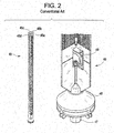
- FIG. 2 illustrates a conventional control rod 45.
- the typical control rod blade 10 includes four wings 45a, 45b, 45c, and 45d arranged in a cruciform shape.
- Each of the wings 45a, 45b, 45c, and 45d include a neutron absorbing material.
- control rod blades 45 are arranged below the fuel assemblies 35 and are latched to control rod drives that enter the reactor pressure vessel through a housing welded to the bottom head of the reactor pressure vessel.
- the drives are basically hydraulic cylinders, operated by hydraulic control units. In operation, a control rod drive may move a control rod 45 upwards and between four fuel assemblies 35 in order to moderate/control the activity of the nuclear reactor.
- FIG. 2 illustrates a detailed section of a bottom 46 of a control rod blade 45.
- the bottom 46 of the control rod blade 45 includes a velocity limiter 48, a coupling socket 47, and a D-handle 49.
- a velocity limiter 48 For maintenance purposes it may be desirable to unlatch the control rod blades 45 from their respective control rod drives.
- the control rod D-handle 49 located at the bottom of the control rod 45, must be accessed.
- US 6,501,813B1 relates to a control rod/fuel support grapple and discloses features generally corresponding to the preamble of claim 1 herein.
- JP 2002-243889A relates to a control rod handling device.
- Example embodiments relate to an unlatching tool and in particular to an unlatching tool for unlatching a control rod blade of a nuclear reactor.
- Example embodiments also relate to a method of unlatching a control blade of a nuclear reactor.
- an unlatching tool in accordance with claim 1 herein and includes a baseplate, a first guide member and a second guide member attached to the baseplate, a first frame and a second frame attached to the baseplate, a stepper motor attached to the first frame, a worm drive attached to the first frame, a cable reel shaft attached to the worm drive, a hose wrapped around the cable reel shaft, and a hook attached to a first end of the hose, the hook including a cylindrical sleeve having at least one foldable finger configured to fold and unfold.
- a method of unlatching a control rod is provided in accordance with claim 11 herein.
- first, second, etc. may be used herein to describe various elements, components, regions, layers, and/or sections, these elements, components, regions, layers, and/or sections should not be limited by these terms. These terms are only used to distinguish one element, component, region, layer, and/or section from another element, component, region, layer, and/or section. Thus, a first element, component, region, layer, or section discussed below could be termed a second element, component, region, layer, or section without departing from the teachings of example embodiments.
- spatially relative terms such as “beneath”, “below”, “lower”, “above”, “upper”, and the like, may be used herein for ease of description to describe one element or feature's relationship to another element(s) or feature(s) as illustrated in the figures. It will be understood that the spatially relative terms are intended to encompass different orientations of the device in use or operation in addition to the orientation depicted in the figures. For example, if the device in the figures is turned over, elements described as “below” or “beneath” other elements or features would then be oriented “above” the other elements or features. Thus, the exemplary term “below” can encompass both an orientation of above and below. The device may be otherwise oriented (rotated 90 degrees or at other orientations) and the spatially relative descriptors used herein interpreted accordingly.
- Embodiments described herein will refer to plan views and/or cross-sectional views by way of ideal schematic views. Accordingly, the views may be modified depending on manufacturing technologies and/or tolerances. Therefore, example embodiments are not limited to those shown in the views, but include modifications in configuration formed on the basis of manufacturing processes. Therefore, regions exemplified in figures have schematic properties and shapes of regions shown in figures exemplify specific shapes or regions of elements, and do not limit example embodiments.
- FIG. 3 is an example embodiment of an unlatching tool 100 according to example embodiments.
- the unlatching tool 100 may include a baseplate 110, guide members 120 and 125, a first A-frame 140A, a second A-frame 104B, a cable reel 160 upon which a hydraulic hose 200 may be wrapped, a worm drive 150 which may be configured to rotate the cable reel 160, a stepper motor 155 which may be configured to track a position of the hydraulic hose 200, and a treble hook 180 which may be attached to an end of the hydraulic hose 200.
- the unlatching tool 100 may further include a rotary union 1000 (see FIG. 13 ) to supply hydraulic fluid to the hydraulic hose 200.
- the hydraulic hose may be a twin hose to operate a double acting cylinder. This in turn would utilize a dual rotary union.
- the unlatching tool 100 may further include two parallel circular plates 160A and 160B, which may be used to form the cable reel 160, and a bail handle 170 which may be used to raise or lower the unlatching tool 100.
- the guide members 120 and 125 may respectively include guide stops 130 and 135 which may be configured to engage a grid within a nuclear reactor.
- the baseplate 110 serves as a structural foundation for the unlatching tool 100 and provides a structure to which the guide members 120 and 125 and the A-frame members 140A and 140B attach.
- the A-frame members 140A and 140B in turn provide a structure for supporting the stepper motor 155, the worm drive 150, a reel shaft 400, the cable reel 160, and the rotary union 1000.
- the baseplate 110 is also configured so that the hydraulic hose 200 may move upwards and downwards as the cable reel 160 rotates.
- the baseplate 220 includes a slot 111 through which the hydraulic hose 200 may traverse.
- the baseplate 110 may include a substantially flat upper horizontal surface 118.
- FIG. 4A represents a top view of the baseplate 110 whereas FIG. 4B represents an isometric view of the top plate 110 as viewed from below.
- the upper surface 118 may be bounded by six edges 110a, 110b, 110c, 110d, 110e, and 110f. Thus, the upper surface 118 may resemble an elongated hexagon.
- a first end of the baseplate 110 may be defined by the edges 110b and 110c and a second end of the baseplate 110 may be defined by the edges 110e and 110f.
- edges 110b and 110c may form about a ninety (90) degree angle and the edges 110e and 110f may likewise form an angle of about ninety (90) degrees.
- a slot 111 may be formed through the upper surface 118. As shown in FIG 4A , the slot 111 may be irregularly shaped and may be larger at one end 111a of the slot 111 than at another end 111b of the slot 111. The slot end 111a may be configured to allow the hydraulic hose 200 to pass there through as well as provide a viewing path through the baseplate.
- Structure 112 may be formed under the first end of the baseplate 110 and the second structure 116 may be formed under the second end of the baseplate 110.
- the first structure 112 may be comprised of five (5) plate-like members 112a, 112b, 112c, 112d, and 112e that extend in a direction substantially perpendicular to the upper surface 118.
- the plate-like members 112a and 112b may be substantially in line with, or parallel with edges 110b and 110c, respectively, and edges 112c and 112d may be in line with or parallel with edges 110a and 110d, respectively.
- the fifth member 112e may connect to the plate-like members 112c and 112d and may extend in a direction substantially perpendicular to a direction in which the plate-like members 112c and 112d extend.
- the second structure 116 may be formed under the second end of the baseplate 110.
- the second structure 116 may be comprised of six (6) plate-like members 116a, 116b, 116c, 116d, 116e, and 116f that extend in a direction substantially perpendicular to the upper surface 118.
- the plate-like members 116a and 116b may be substantially in line with, or parallel with edges 110e and 110f, respectively, and edges 116c and 116f may be in line with or parallel with edges 110a and 110d, respectively.
- the plate-like members 116d and 116e may connect to the plate-like members 116c and 116f, respectively and may extend in a direction substantially perpendicular to a direction in which the plate-like members 116c and 116f extend. As is evident from FIG. 4B , there is a gap between the plate-like members 116d and 116e, thus plate-like members 116d and 116e allow for a member/component to traverse in a direction along a length of the baseplate 110 from the second end of the base plate 110 towards a center of the baseplate 110.
- the guides 120 and 125 resemble angle iron having an L-shaped cross-section.
- the guides 120 and 125 may have a length of about 50.8cm (twenty (20) inches) with leg lengths of approximately 10.2cm (four (4) inches).
- the guide 120 may, for example, be attached to the plate-like members 112a and 112b of the first structure 112 of the baseplate 110 via bolting. However, example embodiments are not limited thereto as the guide 120 could be attached to plate-like members 112a and 112b of the first structure 112 by welding or rivoting.
- the guide 125 may be attached to the plate-like members 116a and 116b of the second structure 116 of the baseplate 110 via bolting. However, example embodiments are not limited thereto as the guide 125 could be attached to plate-like members 116a and 116b of the second structure 116 by welding or rivoting.
- FIG. 3 illustrates the first and second guides 120 and 125 as having the same length, example embodiments are not limited thereto as one of the first and second guides 120 and 125 may be longer than the other.
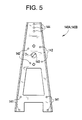
- FIG. 5 illustrates the A-frame 140A. Because the A-frame 140A is similar to the A-frame 140B, for the sake of brevity, only features of the A-frame 140A will be discussed. As shown in FIG. 5 , the A-frame 140A may include a plurality of holes 141 which may be spaced so as to correspond to the holes 141 * formed in the baseplate 110. Accordingly, the A-frame 140A may be attached to the baseplate 110 by bolting the A-frame 140A to the baseplate 110 using the holes 141 and 141*. The A-frame 140A also includes a plurality of holes 142 which may be used to bolt the worm drive 150 to the A-frame 140A.
- the A-frame 140A may also include a hole 143 which may be used to allow a reel shaft 400 to connect to and be driven by the worm drive 150.
- the reel shaft 400 upon rotation, may cause the hydraulic hose 200 to wrap or unwrap around the cable reel 160.
- the A-frame 140A may also include a plurality of holes 144 which may be used to bolt the bail handle 170 to the A-frame 140A.
- FIGS. 6A and 6B are views of a reel shaft 400 that may be used with the unlatching tool 100 of example embodiments.
- the reel shaft 400 may have a stepped shaft configuration with a first stepped portion 410 having a first diameter d1, a second stepped portion 420 having a second diameter d2, a third stepped portion 430 having a variable diameter d3 (see FIG. 6B ), and a fourth stepped portion 440 having a diameter d4.
- the first stepped portion 410 may be configured to engage the worm drive 150 and the second and fourth stepped portions 420 and 440 may be configured to insert through the holes 143 of the A-frames 140A and 140B so that the reel shaft 400 is supported by the A-frames 140A and 140B.
- the diameters d2 and d4 of the second and fourth stepped portions 420 and 440 should be slightly smaller than the diameter D1 of the hole 143.
- the fourth stepped portion 410 may include an end 447 configured to receive hydraulic fluid from the aforementioned rotary union 1000.
- the fourth stepped portion 410 may also include a first hollow channel 445 which may provide the hydraulic fluid from the rotary union 1000 to the third stepped portion 430.
- the third stepped portion may include a second hollow channel (not shown) which provides fluid communication between the hollow channel 445 and a surface S1 which is configured to connect to the hydraulic hose 200.
- hydraulic fluid may enter the reel shaft 400 through the first hollow channel 445 and may traverse through the second hollow channel to the surface S1 that may be connected to the hydraulic hose 200.
- the hydraulic hose 200 may wrap around the third stepped portion when the reel shaft 400 rotates.
- the third stepped portion 430 includes a sub-stepped portion having a diameter d5.
- the two parallel plates 160A and 160B may be annular shaped and each of the plates may have an inner diameter that is slightly larger than the diameter d5, and an outer diameter which is larger than the largest diameter d3.
- the two parallel plates 160A and 160B may be arranged on the sub-step portion of the sides of the third stepped portion 430. Accordingly, the two parallel plates 160A and 160B may prevent the hydraulic hose 200 from slipping off of the third stepped portion 430 as the shaft 400 rotates.
- FIG. 7 shows a section view of the unlatching tool 100 in accordance with example embodiments.
- the unlatching tool also includes an arm 510 pivotably attached to the A-frame 104A.
- the arm 510 includes a wheel 520 configured to engage the hydraulic hose 200.
- FIG. 7 also shows a cylinder 500 which may have one end attached to the arm 510 and another end attached to the baseplate 110. The cylinder 500 may be used to move the arm 510 backwards and forwards thus finely positioning the hydraulic hose 200.
- the cylinder 500 may be configured with a pressure sensor in order to determine whether the hydraulic hose 200 with the treble hook 180 has engaged a D-handle of a control rod.
- a pressure sensor placed on the pressure line connected to the cylinder 500 may determine whether or not the D-handle has been engaged by sensing whether or not the cylinder 500 is in tension.
- FIGS. 8A and 8B represent a detailed example of the treble hook 180 with FIG. 8A illustrating a folded configuration and FIG. 8B illustrating an unfolded configuration.
- the treble hook 180 is comprised of a hydraulic cylinder 181, a hook rod 183, three fingers 184, 185, and 186, and a sleeve 182.
- the sleeve 182 may be cylindrical, however, example embodiments are not limited thereto. Also, the use of just one or two fingers and be accommodated.
- the cylinder is a single acting cylinder with a spring return, but it could utilize a double acting cylinder, which in turn would need a twin hose assembly.
- a first end of the hook rod 183 may be connected to the hydraulic cylinder 181.
- the fingers 184, 185, and 186 may have ends pinned within the sleeve 182 and the ends may be pinned at different elevations.
- the fingers may be arranged to that, in an unfolded state, the fingers 184, 185, and 186 form projections which are spaced 180 degrees apart.
- the fingers 184, 185, and 186 may include slots which interact with protrusions protruding from the hook rod 183.
- the sleeve 182 may at least partially enclose the hydraulic cylinder 181 and may entirely enclose the hook rod 183, and the three fingers 184, 185, and 186.
- FIG. 9 is a detailed drawing showing the arrangement of the third finger 186 within the sleeve 182.
- the third finger 186 may be pinned to the sleeve 182 via the pin 190.
- the third finger 186 also includes a slot 192 which interacts with a protrusion 194 extending from the hook rod 183.
- the protrusion 194 applies an upward force to the finger 183 at the slot 192 thus causing the third finger 186 to rotate into the sleeve 183 to obtain a folded state.
- a downward movement of the hook rod 182 will cause the finger 186 to unfold.
- the fingers 183 and 184 may be similarly connected to the hook rod 183 and the sleeve 182 and may therefore function similarly, accordingly, a detailed discussion of the kinematics of these fingers is omitted for the sake of brevity.
- a treble hook 180 including three fingers 184, 185, and 186 has been described, example embodiments are not limited thereto.
- a hook 180 may include more than three fingers or less than three fingers.
- the hook would include a hook rod with a protrusion that engages a slot of only a single finger.
- the hook with the single finger would be identical to the above described treble hook.
- an unlatching tool 100 may include a baseplate 110 with guide members 120 and 125 attached thereto.
- the guide members 120 and 125 may include guide stops 130 and 135 which may be configured to engage a grid within a conventional nuclear power plant.
- the baseplate 110 also supports, via A-frames 140A and 140B, a stepper motor 155 and a worm drive 150.
- the baseplate 110 further supports, via the A-frames 140A and 140B, a reel shaft 400 supporting a hydraulic hose 200.
- the reel shaft 400 may be connected to the worm drive 150 and the worm drive may rotate the reel shaft 400.
- the hydraulic hose 200 may be wrapped around the reel shaft 400.
- One end of the hydraulic hose 200 may be connected to the reel shaft 400 and another end of the hydraulic hose 200 may be connected to a treble hook 400.
- hydraulic fluid may be provided to the treble hook via the rotary union 1000, the reel shaft 400, and the hydraulic hose 200.
- the rotary union 1000 may be connected to one end of the reel shaft 400 which may be configured with the first hollow channel 445.
- the first hollow channel 445 may be in fluid communication with a second hollow channel which may in turn terminate at a surface S1 connected to the hydraulic hose 200.
- hydraulic fluid provided by the rotary union 1000 may flow through the first hollow channel 445 and through the second hollow channel and then to the hydraulic hose 200.
- the hydraulic fluid may then pass through the hydraulic hose 200 and to the treble hook 180.
- the hydraulic fluid may then cause the hydraulic cylinder 181 within the treble hook 180 to move the hook rod 183 thus actuating the fingers 184, 185 and 186.
- the treble hook 180 may be move upwards or downwards by the rotation of the reel shaft 400. Because the rotation of the reel shaft 400 is controlled by the worm drive 150, the worm drive 150 controls the vertical movement of the treble hook 180.
- the stepper motor 155 may be used to track the movement of the worm drive 150. Thus the stepper motor 155 may provide feedback to a user regarding how far the treble hook 180 has moved.
- the hydraulic cable 200 may engage a wheel 520 that may be attached to an arm 510 than may in turn have a first end that may be pivotably connected to one of the A-frames 140A and 140B.
- the arm 510 may also be attached to a cylinder 500 that may be connected to the baseplate 110.
- the cylinder may expand or contract and thus may be able to laterally position/reposition the hydraulic hose 200.
- the cylinder 500 may include a pressure sensor 500 that may determine whether the cylinder 500 is in tension or in compression. Whether or not the cylinder 500 is in tension or compression may depend on whether the treble hook 180 is engaged with a D-hook of a control rod 45.
- the cylinder 500 serves a dual purpose of positioning the hydraulic hose 200 and determining whether the treble hook is engaged with a D-hook of a control rod 45.
- the unlatching tool 100 may be used to unlatch a control rod blade from a control rod drive.
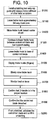
- FIG. 10 illustrates a flowchart detailing the operations that may be used for unlatching a control rod blade from a control rod drive using the unlatching tool 100. These operations take advantage of existing structure that are typically found in a conventional nuclear power plant, for example, the crane 15, the top guide 30, and the fuel support casting 40 along with the conventional control rod blade 45.
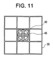
- FIG. 11 illustrates a top view of a control rod blade 45 and a support casting 40 when viewed through the top guide 30. For simplicity only a single control rod blade 45 and support casting 40 are shown.
- FIG. 12 illustrates an operation of moving the unlatching tool 100 over and above a cell within the grid 30 (S1000).
- This operation involves using a mono-rail hoist or other hoist system, for example, the crane 15 illustrated in FIG. 1 , to move the unlatching tool 100 above the cell.
- the unlatching tool 100 may be lowered into the cell via the monorail hoist system.
- the unlatching tool 100 may be configured to be supported by a cell of the top guide 30.
- FIG. 13 illustrates an unlatching tool 100 installed in a cell of the top guide 30.
- the guides 120 and 125 may be configured to nearly touch inside surfaces of the cell, however, the unlatching tool 100 is prevented from passing completely through the cell by the guide stops 130 and 135 provided on outside surfaces of the guides 120 and 125.
- bottom surfaces of the guide stops 130 and 135 contact top surfaces of the grid 30 allowing for the unlatching tool 100 to be stably supported by the grid 30.
- the worm drive 150 may be operated and the cable reel 160 may be rotated to lower the treble hook 180 below the grid.
- the treble hook 180 may be lowered, for example, approximately 3 ⁇ 4 of the way down to the core before any repositioning of the treble hook 180 (S 1100).
- the travel distance of the treble hook may be monitored by an operator using the stepper motor 155. Thus, an operator will have data available, via the stepper motor 155, regarding the position of the treble hook 180.
- the treble hook 180 may be repositioned towards the center of the cell so that the treble hook 180 may pass between the control rod 45 and the support casting 40 (S1200).
- the treble hook 180 may be repositioned by extending or contracting the cylinder 500 which is coupled to the baseplate 110 and the arm 510.
- FIGS. 14A and 14B illustrate an example of the treble hook 180 being repositioned near the center of the cell with FIG. 14A representing an isometric view and FIG. 14B representing a top view. As shown in FIGS. 14A and 14B , the treble hook 180 may be moved to a region in the cell where it can be lowered between the support casting 40 and the control rod 45
- the treble hook 180 may moved downwards between the control rod 45 and the support casting 40 (S 1300).
- the treble hook 180 may be very near a corner formed by two wings of the control rod 45.
- the treble hook 180 continues to move until it reaches the base of the control rod 45 (S 1400).
- the fingers 184, 185, and 186 of the treble hook 180 may be deployed (S 1500).
- FIGS. 15A and 15B show an example of the treble hook 180 being arranged near the bottom of the control rod 45.
- the fingers 184, 185, and 186 may be employed by providing hydraulic fluid to the hydraulic cylinder 181 of the treble hook 180.
- the hydraulic fluid may be provided by the rotary union 1000 which may provide the hydraulic fluid to the a reel shaft 400 which may in turn provide the hydraulic fluid to the hydraulic hose 200 which may in turn provide the hydraulic fluid to the hydraulic cylinder 181.
- the cylinder 500 determines the hydraulic hose 200 is in tension it is determined that the D-handle has been engaged and the control rod 45 has been unlatched (S1900). In the event it is determined that the control rod 45 has not been unlatched, a withdrawal sequence involving an upward motion of about two (2) to about three (3) inches before a downward motion is made is executed (S2000). During this operation, the hose tension shall be maintained by monitoring the pressure in the cylinder 500 and adjusting the stepper motor.
- a treble hook with three fingers 184, 185, and 186 is employed, however, example embodiments are not limited thereto.
- a single hook with one foldable finger may be used.
- the hose may be configured to keep the single hook aligned with the D-handle.
- the hose could be a hydraulic hose which does not twist, for example, a twin hose for a "flat" hose.
- the process may be implemented with the aid of a remote control camera system (GEROCS) in order to aid in the positioning of any of the aforementioned unlatching tool components.
- GEROCS remote control camera system
Landscapes
- Physics & Mathematics (AREA)
- Engineering & Computer Science (AREA)
- Plasma & Fusion (AREA)
- General Engineering & Computer Science (AREA)
- High Energy & Nuclear Physics (AREA)
- Storing, Repeated Paying-Out, And Re-Storing Of Elongated Articles (AREA)
- Actuator (AREA)
- Other Liquid Machine Or Engine Such As Wave Power Use (AREA)
Description
- Example embodiments relate to an unlatching tool and in particular to an unlatching tool for unlatching a control rod blade of a nuclear reactor. Example embodiments also relate to a method of unlatching a control blade of a nuclear reactor.
-
FIG. 1 illustrates a simplified diagram of a typical boilingwater reactor building 10. As shown inFIG. 1 , a typicalnuclear reactor building 10 houses, among other things, acrane 15, which may be used to move relatively heavy equipment in thereactor building 10. Thereactor building 10 also houses a nuclearreactor pressure vessel 20 which includes a dome-shapedtop head 25, a plurality offuel assemblies 35, and a plurality ofcontrol rods 45. Atop guide 30 is arranged over thefuel assemblies 35 and resembles a grid having a plurality of rectangular cells. At the bottom of thefuel assemblies 35 is afuel support casting 40 and below thefuel support casting 40 areguide tubes 50 housing thecontrol rod blades 45. -
FIG. 2 illustrates aconventional control rod 45. As shown inFIG. 2 , the typicalcontrol rod blade 10 includes fourwings wings - In a typical reactor assembly, the
control rod blades 45 are arranged below thefuel assemblies 35 and are latched to control rod drives that enter the reactor pressure vessel through a housing welded to the bottom head of the reactor pressure vessel. The drives are basically hydraulic cylinders, operated by hydraulic control units. In operation, a control rod drive may move acontrol rod 45 upwards and between fourfuel assemblies 35 in order to moderate/control the activity of the nuclear reactor. -
FIG. 2 illustrates a detailed section of abottom 46 of acontrol rod blade 45. Thebottom 46 of thecontrol rod blade 45 includes avelocity limiter 48, acoupling socket 47, and a D-handle 49. For maintenance purposes it may be desirable to unlatch thecontrol rod blades 45 from their respective control rod drives. However, in order to unlatch thecontrol rods 45 from the control rod drives, the control rod D-handle 49, located at the bottom of thecontrol rod 45, must be accessed. -
US 6,501,813B1 relates to a control rod/fuel support grapple and discloses features generally corresponding to the preamble ofclaim 1 herein.JP 2002-243889A - Example embodiments relate to an unlatching tool and in particular to an unlatching tool for unlatching a control rod blade of a nuclear reactor. Example embodiments also relate to a method of unlatching a control blade of a nuclear reactor.
- In accordance with one aspect of the invention, an unlatching tool is provided in accordance with
claim 1 herein and includes a baseplate, a first guide member and a second guide member attached to the baseplate, a first frame and a second frame attached to the baseplate, a stepper motor attached to the first frame, a worm drive attached to the first frame, a cable reel shaft attached to the worm drive, a hose wrapped around the cable reel shaft, and a hook attached to a first end of the hose, the hook including a cylindrical sleeve having at least one foldable finger configured to fold and unfold. - In accordance with another aspect of the invention, a method of unlatching a control rod is provided in accordance with claim 11 herein.
- Example embodiments of the present invention will be more clearly understood from the following detailed description taken in conjunction with the accompanying drawings.
-
FIG. 1 is a simplified view of a typical boiling water reactor building; -
FIG. 2 is a view of a conventional control rod blade; -
FIG. 3 is a view of an unlatching tool according to example embodiments; -
FIGS. 4A and 4B are views of a baseplate of an unlatching tool according to example embodiments; -
FIG. 5 is a view of an A-frame of an unlatching tool according to example embodiments; -
FIGS. 6A and 6B are views of a reel shaft of an unlatching tool according to example embodiments; -
FIG. 7 is a view of an unlatching tool according to example embodiments; -
FIGS. 8A and 8B are views of treble hook according to example embodiments; -
FIG. 9 is a close-up view of a treble hook according to example embodiments; -
FIG. 10 is a flowchart for unlatching a control rod in accordance with example embodiments; -
FIG. 11 is top view of a control rod and a support casting as viewed through a grid in accordance with example embodiments; -
FIG. 12 is a view of an unlatching device engaged with a grid in accordance with example embodiments; -
FIG. 13 is a top view of an unlatching device engaged with a grid in accordance with example embodiments; -
FIGS. 14A and14B are views of a treble hook being lowered between a control rod and a support casting in accordance with example embodiments; and -
FIGS. 15A and 15B are views of a treble hook with fingers deployed against a control rod in accordance with example embodiments. - Example embodiments of the invention will now be described more fully with reference to the accompanying drawings, in which example embodiments are shown. The invention may, however, be embodied in different forms within the scope of the appended claims.
- The embodiments are provided so that this disclosure will be thorough and complete.
- In the drawings, the sizes of components may be exaggerated for clarity.
- It will be understood that when an element or layer is referred to as being "on", "connected to", or "coupled to" another element or layer, it can be directly on, connected to, or coupled to the other element or layer or intervening elements or layers that may be present. In contrast, when an element is referred to as being "directly on", "directly connected to", or "directly coupled to" another element or layer, there are no intervening elements or layers present. As used herein, the term "and/or" includes any and all combinations of one or more of the associated listed items.
- It will be understood that, although the terms first, second, etc. may be used herein to describe various elements, components, regions, layers, and/or sections, these elements, components, regions, layers, and/or sections should not be limited by these terms. These terms are only used to distinguish one element, component, region, layer, and/or section from another element, component, region, layer, and/or section. Thus, a first element, component, region, layer, or section discussed below could be termed a second element, component, region, layer, or section without departing from the teachings of example embodiments.
- Spatially relative terms, such as "beneath", "below", "lower", "above", "upper", and the like, may be used herein for ease of description to describe one element or feature's relationship to another element(s) or feature(s) as illustrated in the figures. It will be understood that the spatially relative terms are intended to encompass different orientations of the device in use or operation in addition to the orientation depicted in the figures. For example, if the device in the figures is turned over, elements described as "below" or "beneath" other elements or features would then be oriented "above" the other elements or features. Thus, the exemplary term "below" can encompass both an orientation of above and below. The device may be otherwise oriented (rotated 90 degrees or at other orientations) and the spatially relative descriptors used herein interpreted accordingly.
- Embodiments described herein will refer to plan views and/or cross-sectional views by way of ideal schematic views. Accordingly, the views may be modified depending on manufacturing technologies and/or tolerances. Therefore, example embodiments are not limited to those shown in the views, but include modifications in configuration formed on the basis of manufacturing processes. Therefore, regions exemplified in figures have schematic properties and shapes of regions shown in figures exemplify specific shapes or regions of elements, and do not limit example embodiments.
-
FIG. 3 is an example embodiment of anunlatching tool 100 according to example embodiments. Theunlatching tool 100 may include abaseplate 110, guidemembers first A-frame 140A, a second A-frame 104B, acable reel 160 upon which a hydraulic hose 200 may be wrapped, aworm drive 150 which may be configured to rotate thecable reel 160, astepper motor 155 which may be configured to track a position of the hydraulic hose 200, and atreble hook 180 which may be attached to an end of the hydraulic hose 200. Though not shown inFIG. 3 , theunlatching tool 100 may further include a rotary union 1000 (seeFIG. 13 ) to supply hydraulic fluid to the hydraulic hose 200. Although not shown, the hydraulic hose may be a twin hose to operate a double acting cylinder. This in turn would utilize a dual rotary union. Theunlatching tool 100 may further include two parallelcircular plates cable reel 160, and abail handle 170 which may be used to raise or lower theunlatching tool 100. Theguide members - The
baseplate 110 serves as a structural foundation for theunlatching tool 100 and provides a structure to which theguide members A-frame members A-frame members stepper motor 155, theworm drive 150, areel shaft 400, thecable reel 160, and therotary union 1000. Thebaseplate 110 is also configured so that the hydraulic hose 200 may move upwards and downwards as thecable reel 160 rotates. For example, the baseplate 220 includes aslot 111 through which the hydraulic hose 200 may traverse. - In greater detail, and referring to
FIGS. 4A and 4B , thebaseplate 110 may include a substantially flat upperhorizontal surface 118.FIG. 4A represents a top view of thebaseplate 110 whereasFIG. 4B represents an isometric view of thetop plate 110 as viewed from below. Theupper surface 118 may be bounded by sixedges upper surface 118 may resemble an elongated hexagon. As shown inFIG. 4A , a first end of thebaseplate 110 may be defined by theedges baseplate 110 may be defined by theedges edges edges slot 111 may be formed through theupper surface 118. As shown inFIG 4A , theslot 111 may be irregularly shaped and may be larger at oneend 111a of theslot 111 than at anotherend 111b of theslot 111. Theslot end 111a may be configured to allow the hydraulic hose 200 to pass there through as well as provide a viewing path through the baseplate. - Below the
upper surface 118 of thebaseplate 110 are twostructures FIG. 4B .Structure 112 may be formed under the first end of thebaseplate 110 and thesecond structure 116 may be formed under the second end of thebaseplate 110. Thefirst structure 112 may be comprised of five (5) plate-like members upper surface 118. The plate-like members edges edges fifth member 112e may connect to the plate-like members like members - As described above, the
second structure 116 may be formed under the second end of thebaseplate 110. Thesecond structure 116 may be comprised of six (6) plate-like members upper surface 118. The plate-like members edges edges like members like members like members FIG. 4B , there is a gap between the plate-like members like members baseplate 110 from the second end of thebase plate 110 towards a center of thebaseplate 110. - In example embodiments, the
guides guides guide 120 may, for example, be attached to the plate-like members first structure 112 of thebaseplate 110 via bolting. However, example embodiments are not limited thereto as theguide 120 could be attached to plate-like members first structure 112 by welding or rivoting. Similarly, theguide 125 may be attached to the plate-like members second structure 116 of thebaseplate 110 via bolting. However, example embodiments are not limited thereto as theguide 125 could be attached to plate-like members second structure 116 by welding or rivoting. - Although
FIG. 3 illustrates the first andsecond guides second guides -
FIG. 5 illustrates theA-frame 140A. Because theA-frame 140A is similar to theA-frame 140B, for the sake of brevity, only features of theA-frame 140A will be discussed. As shown inFIG. 5 , theA-frame 140A may include a plurality ofholes 141 which may be spaced so as to correspond to theholes 141 * formed in thebaseplate 110. Accordingly, theA-frame 140A may be attached to thebaseplate 110 by bolting theA-frame 140A to thebaseplate 110 using theholes A-frame 140A also includes a plurality ofholes 142 which may be used to bolt theworm drive 150 to theA-frame 140A. TheA-frame 140A may also include ahole 143 which may be used to allow areel shaft 400 to connect to and be driven by theworm drive 150. Thereel shaft 400, upon rotation, may cause the hydraulic hose 200 to wrap or unwrap around thecable reel 160. TheA-frame 140A may also include a plurality ofholes 144 which may be used to bolt thebail handle 170 to theA-frame 140A. -
FIGS. 6A and 6B are views of areel shaft 400 that may be used with theunlatching tool 100 of example embodiments. As shown inFIG. 6A , thereel shaft 400 may have a stepped shaft configuration with a first steppedportion 410 having a first diameter d1, a second steppedportion 420 having a second diameter d2, a third steppedportion 430 having a variable diameter d3 (seeFIG. 6B ), and a fourth steppedportion 440 having a diameter d4. In example embodiments the first steppedportion 410 may be configured to engage theworm drive 150 and the second and fourth steppedportions holes 143 of the A-frames 140A and 140B so that thereel shaft 400 is supported by theA-frames portions hole 143. - The fourth stepped
portion 410 may include anend 447 configured to receive hydraulic fluid from theaforementioned rotary union 1000. The fourth steppedportion 410 may also include a firsthollow channel 445 which may provide the hydraulic fluid from therotary union 1000 to the third steppedportion 430. The third stepped portion may include a second hollow channel (not shown) which provides fluid communication between thehollow channel 445 and a surface S1 which is configured to connect to the hydraulic hose 200. Thus, hydraulic fluid may enter thereel shaft 400 through the firsthollow channel 445 and may traverse through the second hollow channel to the surface S1 that may be connected to the hydraulic hose 200. In example embodiments the hydraulic hose 200 may wrap around the third stepped portion when thereel shaft 400 rotates. - In example embodiments, the third stepped
portion 430 includes a sub-stepped portion having a diameter d5. In example embodiments, the twoparallel plates parallel plates portion 430. Accordingly, the twoparallel plates portion 430 as theshaft 400 rotates. -
FIG. 7 shows a section view of theunlatching tool 100 in accordance with example embodiments. In addition to the aforementioned elements; the unlatching tool also includes anarm 510 pivotably attached to the A-frame 104A. As shown inFIG. 7 , thearm 510 includes awheel 520 configured to engage the hydraulic hose 200.FIG. 7 also shows acylinder 500 which may have one end attached to thearm 510 and another end attached to thebaseplate 110. Thecylinder 500 may be used to move thearm 510 backwards and forwards thus finely positioning the hydraulic hose 200. In addition, thecylinder 500 may be configured with a pressure sensor in order to determine whether the hydraulic hose 200 with thetreble hook 180 has engaged a D-handle of a control rod. For example, if the D-handle has been engaged, the hydraulic hose 200 will be in a tensioned state thus causing thewheel 520 to move away from thecylinder 500 placing thecylinder 500 in tension. Accordingly, a pressure sensor placed on the pressure line connected to thecylinder 500 may determine whether or not the D-handle has been engaged by sensing whether or not thecylinder 500 is in tension. -
FIGS. 8A and 8B represent a detailed example of thetreble hook 180 withFIG. 8A illustrating a folded configuration andFIG. 8B illustrating an unfolded configuration. As shown inFIGS. 8A and 8B , thetreble hook 180 is comprised of ahydraulic cylinder 181, ahook rod 183, threefingers sleeve 182. In example embodiments, thesleeve 182 may be cylindrical, however, example embodiments are not limited thereto. Also, the use of just one or two fingers and be accommodated. As shown, the cylinder is a single acting cylinder with a spring return, but it could utilize a double acting cylinder, which in turn would need a twin hose assembly. A first end of thehook rod 183 may be connected to thehydraulic cylinder 181. Thus, as thehydraulic cylinder 181 is actuated, thehook rod 183 may move through thesleeve 182. Thefingers sleeve 182 and the ends may be pinned at different elevations. In addition, the fingers may be arranged to that, in an unfolded state, thefingers fingers hook rod 183. Thesleeve 182 may at least partially enclose thehydraulic cylinder 181 and may entirely enclose thehook rod 183, and the threefingers -
FIG. 9 is a detailed drawing showing the arrangement of thethird finger 186 within thesleeve 182. Referring toFIG. 9 , thethird finger 186 may be pinned to thesleeve 182 via thepin 190. Thethird finger 186 also includes aslot 192 which interacts with aprotrusion 194 extending from thehook rod 183. In the event thehook rod 183 is drawn upwards, for example, due to an upward movement of thehydraulic cylinder 181, theprotrusion 194 applies an upward force to thefinger 183 at theslot 192 thus causing thethird finger 186 to rotate into thesleeve 183 to obtain a folded state. Conversely, a downward movement of thehook rod 182 will cause thefinger 186 to unfold. Thefingers hook rod 183 and thesleeve 182 and may therefore function similarly, accordingly, a detailed discussion of the kinematics of these fingers is omitted for the sake of brevity. - Although a
treble hook 180 including threefingers hook 180 may include more than three fingers or less than three fingers. For example, in the event the hook includes only one finger, the hook would include a hook rod with a protrusion that engages a slot of only a single finger. Other than that, the hook with the single finger would be identical to the above described treble hook. - As described above, an
unlatching tool 100, according to example embodiments, may include abaseplate 110 withguide members guide members baseplate 110 also supports, viaA-frames stepper motor 155 and aworm drive 150. Thebaseplate 110 further supports, via the A-frames 140A and 140B, areel shaft 400 supporting a hydraulic hose 200. In example embodiments, thereel shaft 400 may be connected to theworm drive 150 and the worm drive may rotate thereel shaft 400. The hydraulic hose 200 may be wrapped around thereel shaft 400. One end of the hydraulic hose 200 may be connected to thereel shaft 400 and another end of the hydraulic hose 200 may be connected to atreble hook 400. - In example embodiments, hydraulic fluid may be provided to the treble hook via the
rotary union 1000, thereel shaft 400, and the hydraulic hose 200. For example, in example embodiments, therotary union 1000 may be connected to one end of thereel shaft 400 which may be configured with the firsthollow channel 445. The firsthollow channel 445 may be in fluid communication with a second hollow channel which may in turn terminate at a surface S1 connected to the hydraulic hose 200. Thus, hydraulic fluid provided by therotary union 1000 may flow through the firsthollow channel 445 and through the second hollow channel and then to the hydraulic hose 200. The hydraulic fluid may then pass through the hydraulic hose 200 and to thetreble hook 180. The hydraulic fluid may then cause thehydraulic cylinder 181 within thetreble hook 180 to move thehook rod 183 thus actuating thefingers - According to the invention, the
treble hook 180 may be move upwards or downwards by the rotation of thereel shaft 400. Because the rotation of thereel shaft 400 is controlled by theworm drive 150, theworm drive 150 controls the vertical movement of thetreble hook 180. Thestepper motor 155 may be used to track the movement of theworm drive 150. Thus thestepper motor 155 may provide feedback to a user regarding how far thetreble hook 180 has moved. - In example embodiments, the hydraulic cable 200 may engage a
wheel 520 that may be attached to anarm 510 than may in turn have a first end that may be pivotably connected to one of the A-frames 140A and 140B. Thearm 510 may also be attached to acylinder 500 that may be connected to thebaseplate 110. The cylinder may expand or contract and thus may be able to laterally position/reposition the hydraulic hose 200. Thecylinder 500 may include apressure sensor 500 that may determine whether thecylinder 500 is in tension or in compression. Whether or not thecylinder 500 is in tension or compression may depend on whether thetreble hook 180 is engaged with a D-hook of acontrol rod 45. Thus, thecylinder 500 serves a dual purpose of positioning the hydraulic hose 200 and determining whether the treble hook is engaged with a D-hook of acontrol rod 45. - The
unlatching tool 100 may be used to unlatch a control rod blade from a control rod drive.FIG. 10 illustrates a flowchart detailing the operations that may be used for unlatching a control rod blade from a control rod drive using theunlatching tool 100. These operations take advantage of existing structure that are typically found in a conventional nuclear power plant, for example, thecrane 15, thetop guide 30, and the fuel support casting 40 along with the conventionalcontrol rod blade 45. -
FIG. 11 illustrates a top view of acontrol rod blade 45 and a support casting 40 when viewed through thetop guide 30. For simplicity only a singlecontrol rod blade 45 and support casting 40 are shown. -
FIG. 12 illustrates an operation of moving theunlatching tool 100 over and above a cell within the grid 30 (S1000). This operation involves using a mono-rail hoist or other hoist system, for example, thecrane 15 illustrated inFIG. 1 , to move theunlatching tool 100 above the cell. Using theguide members unlatching tool 100 may be lowered into the cell via the monorail hoist system. - In example embodiments, the
unlatching tool 100 may be configured to be supported by a cell of thetop guide 30. For example,FIG. 13 illustrates anunlatching tool 100 installed in a cell of thetop guide 30. As shown inFIG. 13 , theguides unlatching tool 100 is prevented from passing completely through the cell by the guide stops 130 and 135 provided on outside surfaces of theguides FIG. 13 , bottom surfaces of the guide stops 130 and 135 contact top surfaces of thegrid 30 allowing for theunlatching tool 100 to be stably supported by thegrid 30. - After the
unlatching tool 100 has been moved to thegrid 30, theworm drive 150 may be operated and thecable reel 160 may be rotated to lower thetreble hook 180 below the grid. Thetreble hook 180 may be lowered, for example, approximately ¾ of the way down to the core before any repositioning of the treble hook 180 (S 1100). The travel distance of the treble hook may be monitored by an operator using thestepper motor 155. Thus, an operator will have data available, via thestepper motor 155, regarding the position of thetreble hook 180. After thetreble hook 180 has been lowered approximately ¾ of the way down the core, thetreble hook 180 may be repositioned towards the center of the cell so that thetreble hook 180 may pass between thecontrol rod 45 and the support casting 40 (S1200). Thetreble hook 180 may be repositioned by extending or contracting thecylinder 500 which is coupled to thebaseplate 110 and thearm 510.FIGS. 14A and14B illustrate an example of thetreble hook 180 being repositioned near the center of the cell withFIG. 14A representing an isometric view andFIG. 14B representing a top view. As shown inFIGS. 14A and14B , thetreble hook 180 may be moved to a region in the cell where it can be lowered between the support casting 40 and thecontrol rod 45 - After the
treble hook 180 has been moved towards the center of the cell, thetreble hook 180 may moved downwards between thecontrol rod 45 and the support casting 40 (S 1300). In example embodiments, thetreble hook 180 may be very near a corner formed by two wings of thecontrol rod 45. Thetreble hook 180 continues to move until it reaches the base of the control rod 45 (S 1400). At this time, thefingers treble hook 180 may be deployed (S 1500).FIGS. 15A and 15B show an example of thetreble hook 180 being arranged near the bottom of thecontrol rod 45. In example embodiments, thefingers hydraulic cylinder 181 of thetreble hook 180. The hydraulic fluid may be provided by therotary union 1000 which may provide the hydraulic fluid to the areel shaft 400 which may in turn provide the hydraulic fluid to the hydraulic hose 200 which may in turn provide the hydraulic fluid to thehydraulic cylinder 181. - After the
fingers treble hook 180 may be slowly raised by operating theworm drive 150 to rotate the reel shaft 160 (S1600). Because thefingers control rod 45 and the third finger may align with a center of the control rod 45 (seeFIG. 15B ). Thus, as thetreble hook 180 is raised, the finger not in contact with the wings of thecontrol rod 45 engages with the D-handle of thecontrol 45. As thetreble hook 180 is raised, the load on the hose is monitored by the cylinder 500 (S 1700) and the position is determined by the stepper motor 155 (S 1800). If thecylinder 500 determines the hydraulic hose 200 is in tension it is determined that the D-handle has been engaged and thecontrol rod 45 has been unlatched (S1900). In the event it is determined that thecontrol rod 45 has not been unlatched, a withdrawal sequence involving an upward motion of about two (2) to about three (3) inches before a downward motion is made is executed (S2000). During this operation, the hose tension shall be maintained by monitoring the pressure in thecylinder 500 and adjusting the stepper motor. - In the above example embodiment, a treble hook with three
fingers - The foregoing is illustrative of example embodiments and is not to be construed as limiting thereof. Although a few example embodiments have been described, those skilled in the art will readily appreciate that many modifications are possible in the example embodiments within the scope of the appended claims.
Claims (15)
- An unlatching tool (100) comprising:a baseplate (110);a first guide member (120) and a second guide member (125) attached to the baseplate (110);a first frame (140A) and a second frame (140B) attached to the baseplate (110);a worm drive (150) attached to the first frame (140A);a cable reel shaft (400) attached to the worm drive (150);a hook (180), the hook (180) including a cylindrical sleeve (182) having at least one finger (184,185,186) configured to fold and unfold; characterized in that the unlatching tool further comprises:a stepper motor (155) attached to the first frame (140A); anda hose (200) wrapped around the cable reel shaft(400), wherein the hook (180) is attached to a first end of the hose (200).
- The unlatching tool (100) according to claim 1, wherein the hook (180) is a treble hook that includes a hydraulic cylinder (181) and a hook rod (183) connected to the hydraulic cylinder (181), and the at least one finger (184, 185, 186) includes a first finger (184), a second finger (185), and a third finger (186), and the hook rod (183) includes protrusions (194) engaging slots (192) of the first finger (184), the second finger (185), and the third finger (186).
- The unlatching tool (100) according to claim 2, wherein in the unfolded position the first finger (184) and the second finger (185) form an angle of about 120 degrees, the second finger (185) and the third finger (186) form an angle of about 120 degrees, and the first finger (184) and the third finger (186) form an angle of about 120 degrees.
- The unlatching tool (100) according to claim 3, wherein the first (184), second (185), and third (186) fingers are at different elevations along an axis of the cylindrical sleeve (182).
- The unlatching tool (100) according to any preceding claim, further comprising:a rotary union (1000) configured to provide hydraulic fluid to the hook (180).
- The unlatching tool (100) according to claim 5, wherein
the cable reel shaft (400) includes a first a first hollow channel (445) configured to receive the hydraulic fluid from the rotary union (1000) and a second hollow channel configured to provide fluid communication between the first hollow channel (445) and the hose (200) to transfer the hydraulic fluid to the hose (200). - The unlatching tool (100) according to any preceding claim, further comprising:an arm (510) having a first end pivotably connected to the first frame (140A);a wheel (520) attached to the arm (510), the wheel (520) configured to contact the hose (200); anda cylinder (500) having a first end attached to the baseplate (110) and a second end attached to a second end of the arm (510), the cylinder (500) being configured to adjust a location of the hose (200).
- The unlatching tool (100) according to claim 7, wherein the cylinder (500) includes a sensor to determine whether the cylinder (500) is in one of tension and compression.
- The unlatching tool (100) according to any preceding claim, further comprising:a first guide stop (130) attached to the first guide member (120); anda second guide stop (135) attached to the second guide member (125).
- The unlatching tool (100) according to claim 9, wherein the first guide member (120), the second guide member (125), the first guide stop (130), and the second guide stop (135) have an L-shaped cross-section.
- A method of unlatching a control rod comprising:placing the unlatching tool (100) according to any of the preceding claims on a top guide grid (30), the unlatching tool (100) including a hook (180) with at least one foldable finger (184, 185, 186);lowering the hook (180) to a D handle (49) of the control rod (45); andunfolding the at least one foldable finger (184, 185, 186)such that the at least one foldable finger (184, 185, 186) engages the D handle (49) of the control rod (45).
- The method of claim 11, wherein lowering the hook (180) includes lowering the hook (180) a predetermined distance from the top guide grid (30) to a top of the control rod (45), moving the hook (180) near a center of a cell of the top guide grid (30) on which the unlatching tool (100) is placed, and lowering the hook (180) to a base of the control rod (45).
- The method of claim 12, wherein moving the hook (180) near the center of the cell includes operating a cylinder (500) to rotate an arm (510) of the unlatching tool (100) to move the hook (180).
- The method of claim 13, further comprising:using the cylinder (500) to determine whether or not the D handle has been engaged.
- The method of any of claims 11 to 14, further comprising:using a stepper motor (155) to monitor a location of the hook (180).
Applications Claiming Priority (1)
| Application Number | Priority Date | Filing Date | Title |
|---|---|---|---|
| US12/943,434 US8824618B2 (en) | 2010-11-10 | 2010-11-10 | Control rod blade unlatching tool |
Publications (3)
| Publication Number | Publication Date |
|---|---|
| EP2453442A2 EP2453442A2 (en) | 2012-05-16 |
| EP2453442A3 EP2453442A3 (en) | 2014-08-20 |
| EP2453442B1 true EP2453442B1 (en) | 2015-10-21 |
Family
ID=45002666
Family Applications (1)
| Application Number | Title | Priority Date | Filing Date |
|---|---|---|---|
| EP11188457.3A Active EP2453442B1 (en) | 2010-11-10 | 2011-11-09 | Control rod blade unlatching tool |
Country Status (6)
| Country | Link |
|---|---|
| US (1) | US8824618B2 (en) |
| EP (1) | EP2453442B1 (en) |
| JP (1) | JP2012103253A (en) |
| ES (1) | ES2554486T3 (en) |
| MX (1) | MX2011011969A (en) |
| TW (1) | TWI532055B (en) |
Families Citing this family (1)
| Publication number | Priority date | Publication date | Assignee | Title |
|---|---|---|---|---|
| JP6189040B2 (en) * | 2013-01-31 | 2017-08-30 | 三菱重工業株式会社 | Reactor repair equipment installation apparatus and method |
Family Cites Families (19)
| Publication number | Priority date | Publication date | Assignee | Title |
|---|---|---|---|---|
| JPS5196200U (en) * | 1975-01-29 | 1976-08-02 | ||
| JPS5753111B2 (en) | 1975-02-19 | 1982-11-11 | ||
| US4311557A (en) * | 1979-10-12 | 1982-01-19 | Westinghouse Electric Corp. | Refueling machine for a nuclear reactor |
| GB2072612B (en) | 1980-03-29 | 1983-11-09 | Gagnon P | System for raising and lowering sceneries on a stage |
| US4302176A (en) * | 1980-09-02 | 1981-11-24 | Gordon William F | Tube expander |
| US4907834A (en) * | 1988-02-29 | 1990-03-13 | Xerox Corporation | Multi-finger hydraulic end effector |
| US5016871A (en) * | 1989-11-01 | 1991-05-21 | Proform Fitness Products, Inc. | Exercise machine resistance controller |
| JP2892166B2 (en) | 1991-03-07 | 1999-05-17 | 株式会社東芝 | Reactor refueling machine |
| US5473645A (en) * | 1993-05-21 | 1995-12-05 | General Electric Company | Fuel support and control rod storage rack |
| JPH07333388A (en) | 1994-06-09 | 1995-12-22 | Hitachi Ltd | Working equipment in the reactor |
| US5549636A (en) * | 1994-10-05 | 1996-08-27 | Li Medical Technologies Inc. | Surgical grasper with articulated fingers |
| US5600685A (en) * | 1995-04-24 | 1997-02-04 | General Electric Company | Tool for unlatching extended handle and standard handle control rods |
| US5791228A (en) * | 1996-07-09 | 1998-08-11 | Gervasi; Vito R. | Torque or force amplifying actuator and method for controlling actuator |
| JPH112692A (en) | 1997-06-11 | 1999-01-06 | Toshiba Corp | Control rod and fuel support bracket |
| US6726140B2 (en) * | 2001-01-05 | 2004-04-27 | Westinghouse Electric Company Llc | Take-up reel for flexible elongated members |
| JP2002243889A (en) | 2001-02-22 | 2002-08-28 | Toshiba Corp | Control rod handling device |
| US7441722B2 (en) * | 2001-09-18 | 2008-10-28 | Anthony J. Mancuso | Coil reel hold-down device |
| US6994076B2 (en) | 2004-04-08 | 2006-02-07 | Fleetguard, Inc. | Electrostatic droplet collector with replaceable electrode |
| JP2008256586A (en) | 2007-04-06 | 2008-10-23 | Toshiba Corp | Access device in jet pump riser pipe work, method of using access device, and access device rotation assist device |
-
2010
- 2010-11-10 US US12/943,434 patent/US8824618B2/en not_active Expired - Fee Related
-
2011
- 2011-11-09 ES ES11188457.3T patent/ES2554486T3/en active Active
- 2011-11-09 EP EP11188457.3A patent/EP2453442B1/en active Active
- 2011-11-10 TW TW100141109A patent/TWI532055B/en active
- 2011-11-10 JP JP2011246272A patent/JP2012103253A/en active Pending
- 2011-11-10 MX MX2011011969A patent/MX2011011969A/en active IP Right Grant
Also Published As
| Publication number | Publication date |
|---|---|
| JP2012103253A (en) | 2012-05-31 |
| MX2011011969A (en) | 2012-05-18 |
| US20120114090A1 (en) | 2012-05-10 |
| TWI532055B (en) | 2016-05-01 |
| EP2453442A3 (en) | 2014-08-20 |
| TW201246227A (en) | 2012-11-16 |
| ES2554486T3 (en) | 2015-12-21 |
| US8824618B2 (en) | 2014-09-02 |
| EP2453442A2 (en) | 2012-05-16 |
Similar Documents
| Publication | Publication Date | Title |
|---|---|---|
| EP2593941B1 (en) | Reactor head seismic support tie rod system | |
| CN108285114B (en) | Horizontally hinged platform arm component | |
| CN117509404A (en) | Clamping components and tower lifting equipment | |
| KR101421037B1 (en) | Wire drum supporting apparatus for unwinding work | |
| CN110844004A (en) | A navigation equipment deployment and recovery device and navigation equipment deployment and recovery system | |
| EP2453442A2 (en) | Control rod blade unlatching tool | |
| KR20220062580A (en) | A combination comprising a crane, a load guide device arranged for mounting on a crane, and a load guide device for use in the assembly | |
| WO2008126999A1 (en) | Vertical transferring device for heavy load | |
| CN112299238A (en) | Hoisting tool for nuclear power plant retired upper reactor internals | |
| US5602887A (en) | Tool for pushing tie rod assembly suspended in downcomer annulus of boiling water reactor | |
| JP6628310B2 (en) | Derrick for steel tower assembly and dismantling | |
| CN208333832U (en) | Frame load test platform is equipped to ocean engineering | |
| CN118686431A (en) | A construction device and implementation method for translation and vertical lifting of roof steel trusses | |
| WO2025139244A1 (en) | Cover-opening driving device and cavity apparatus | |
| EP3197808A1 (en) | Reel drive assembly | |
| CN222024003U (en) | Outer arm locking device and loading arm | |
| CN211969262U (en) | Transfer device | |
| CN113896119A (en) | Locking device for rotating mechanism and floating crane rotating mechanism | |
| CN215711018U (en) | Steel construction engineering construction material hoist device | |
| CN223738957U (en) | Circular work device for construction of offshore photovoltaic support units | |
| CN220376150U (en) | Well hoist and mount fixing device | |
| CN111724923B (en) | Support system, support device and reactor refueling method | |
| CN216687081U (en) | Device capable of realizing aerial horizontal movement, torsion and shaking prevention of crane hoist weight | |
| JP2012233759A (en) | Control rod handling device | |
| CN108657943A (en) | Spent Fuel Pool dilatation screen work hanging apparatus |
Legal Events
| Date | Code | Title | Description |
|---|---|---|---|
| PUAI | Public reference made under article 153(3) epc to a published international application that has entered the european phase |
Free format text: ORIGINAL CODE: 0009012 |
|
| AK | Designated contracting states |
Kind code of ref document: A2 Designated state(s): AL AT BE BG CH CY CZ DE DK EE ES FI FR GB GR HR HU IE IS IT LI LT LU LV MC MK MT NL NO PL PT RO RS SE SI SK SM TR |
|
| AX | Request for extension of the european patent |
Extension state: BA ME |
|
| PUAL | Search report despatched |
Free format text: ORIGINAL CODE: 0009013 |
|
| AK | Designated contracting states |
Kind code of ref document: A3 Designated state(s): AL AT BE BG CH CY CZ DE DK EE ES FI FR GB GR HR HU IE IS IT LI LT LU LV MC MK MT NL NO PL PT RO RS SE SI SK SM TR |
|
| AX | Request for extension of the european patent |
Extension state: BA ME |
|
| RIC1 | Information provided on ipc code assigned before grant |
Ipc: G21C 7/12 20060101AFI20140716BHEP Ipc: G21C 19/02 20060101ALI20140716BHEP Ipc: G21C 19/10 20060101ALI20140716BHEP Ipc: G21C 7/14 20060101ALI20140716BHEP Ipc: G21C 19/20 20060101ALI20140716BHEP Ipc: G21C 19/105 20060101ALI20140716BHEP Ipc: G21C 19/115 20060101ALI20140716BHEP |
|
| 17P | Request for examination filed |
Effective date: 20150220 |
|
| RBV | Designated contracting states (corrected) |
Designated state(s): AL AT BE BG CH CY CZ DE DK EE ES FI FR GB GR HR HU IE IS IT LI LT LU LV MC MK MT NL NO PL PT RO RS SE SI SK SM TR |
|
| GRAP | Despatch of communication of intention to grant a patent |
Free format text: ORIGINAL CODE: EPIDOSNIGR1 |
|
| RIC1 | Information provided on ipc code assigned before grant |
Ipc: G21C 19/02 20060101ALI20150526BHEP Ipc: G21C 19/10 20060101ALI20150526BHEP Ipc: G21C 19/105 20060101ALI20150526BHEP Ipc: G21C 7/12 20060101AFI20150526BHEP Ipc: G21C 19/115 20060101ALI20150526BHEP Ipc: G21C 7/14 20060101ALI20150526BHEP Ipc: G21C 19/32 20060101ALI20150526BHEP Ipc: G21C 19/20 20060101ALI20150526BHEP |
|
| INTG | Intention to grant announced |
Effective date: 20150612 |
|
| GRAS | Grant fee paid |
Free format text: ORIGINAL CODE: EPIDOSNIGR3 |
|
| GRAA | (expected) grant |
Free format text: ORIGINAL CODE: 0009210 |
|
| AK | Designated contracting states |
Kind code of ref document: B1 Designated state(s): AL AT BE BG CH CY CZ DE DK EE ES FI FR GB GR HR HU IE IS IT LI LT LU LV MC MK MT NL NO PL PT RO RS SE SI SK SM TR |
|
| REG | Reference to a national code |
Ref country code: GB Ref legal event code: FG4D Ref country code: NL Ref legal event code: MP Effective date: 20151021 |
|
| REG | Reference to a national code |
Ref country code: CH Ref legal event code: EP |
|
| REG | Reference to a national code |
Ref country code: AT Ref legal event code: REF Ref document number: 757052 Country of ref document: AT Kind code of ref document: T Effective date: 20151115 |
|
| REG | Reference to a national code |
Ref country code: IE Ref legal event code: FG4D |
|
| REG | Reference to a national code |
Ref country code: DE Ref legal event code: R096 Ref document number: 602011020750 Country of ref document: DE |
|
| REG | Reference to a national code |
Ref country code: ES Ref legal event code: FG2A Ref document number: 2554486 Country of ref document: ES Kind code of ref document: T3 Effective date: 20151221 |
|
| REG | Reference to a national code |
Ref country code: SE Ref legal event code: TRGR |
|
| REG | Reference to a national code |
Ref country code: LT Ref legal event code: MG4D |
|
| REG | Reference to a national code |
Ref country code: AT Ref legal event code: MK05 Ref document number: 757052 Country of ref document: AT Kind code of ref document: T Effective date: 20151021 |
|
| PG25 | Lapsed in a contracting state [announced via postgrant information from national office to epo] |
Ref country code: HR Free format text: LAPSE BECAUSE OF FAILURE TO SUBMIT A TRANSLATION OF THE DESCRIPTION OR TO PAY THE FEE WITHIN THE PRESCRIBED TIME-LIMIT Effective date: 20151021 Ref country code: NL Free format text: LAPSE BECAUSE OF FAILURE TO SUBMIT A TRANSLATION OF THE DESCRIPTION OR TO PAY THE FEE WITHIN THE PRESCRIBED TIME-LIMIT Effective date: 20151021 Ref country code: IT Free format text: LAPSE BECAUSE OF FAILURE TO SUBMIT A TRANSLATION OF THE DESCRIPTION OR TO PAY THE FEE WITHIN THE PRESCRIBED TIME-LIMIT Effective date: 20151021 Ref country code: IS Free format text: LAPSE BECAUSE OF FAILURE TO SUBMIT A TRANSLATION OF THE DESCRIPTION OR TO PAY THE FEE WITHIN THE PRESCRIBED TIME-LIMIT Effective date: 20160221 Ref country code: LT Free format text: LAPSE BECAUSE OF FAILURE TO SUBMIT A TRANSLATION OF THE DESCRIPTION OR TO PAY THE FEE WITHIN THE PRESCRIBED TIME-LIMIT Effective date: 20151021 Ref country code: NO Free format text: LAPSE BECAUSE OF FAILURE TO SUBMIT A TRANSLATION OF THE DESCRIPTION OR TO PAY THE FEE WITHIN THE PRESCRIBED TIME-LIMIT Effective date: 20160121 |
|
| PG25 | Lapsed in a contracting state [announced via postgrant information from national office to epo] |
Ref country code: GR Free format text: LAPSE BECAUSE OF FAILURE TO SUBMIT A TRANSLATION OF THE DESCRIPTION OR TO PAY THE FEE WITHIN THE PRESCRIBED TIME-LIMIT Effective date: 20160122 Ref country code: PT Free format text: LAPSE BECAUSE OF FAILURE TO SUBMIT A TRANSLATION OF THE DESCRIPTION OR TO PAY THE FEE WITHIN THE PRESCRIBED TIME-LIMIT Effective date: 20160222 Ref country code: PL Free format text: LAPSE BECAUSE OF FAILURE TO SUBMIT A TRANSLATION OF THE DESCRIPTION OR TO PAY THE FEE WITHIN THE PRESCRIBED TIME-LIMIT Effective date: 20151021 Ref country code: AT Free format text: LAPSE BECAUSE OF FAILURE TO SUBMIT A TRANSLATION OF THE DESCRIPTION OR TO PAY THE FEE WITHIN THE PRESCRIBED TIME-LIMIT Effective date: 20151021 Ref country code: RS Free format text: LAPSE BECAUSE OF FAILURE TO SUBMIT A TRANSLATION OF THE DESCRIPTION OR TO PAY THE FEE WITHIN THE PRESCRIBED TIME-LIMIT Effective date: 20151021 Ref country code: LV Free format text: LAPSE BECAUSE OF FAILURE TO SUBMIT A TRANSLATION OF THE DESCRIPTION OR TO PAY THE FEE WITHIN THE PRESCRIBED TIME-LIMIT Effective date: 20151021 Ref country code: FI Free format text: LAPSE BECAUSE OF FAILURE TO SUBMIT A TRANSLATION OF THE DESCRIPTION OR TO PAY THE FEE WITHIN THE PRESCRIBED TIME-LIMIT Effective date: 20151021 |
|
| REG | Reference to a national code |
Ref country code: DE Ref legal event code: R119 Ref document number: 602011020750 Country of ref document: DE |
|
| PG25 | Lapsed in a contracting state [announced via postgrant information from national office to epo] |
Ref country code: CZ Free format text: LAPSE BECAUSE OF FAILURE TO SUBMIT A TRANSLATION OF THE DESCRIPTION OR TO PAY THE FEE WITHIN THE PRESCRIBED TIME-LIMIT Effective date: 20151021 Ref country code: MC Free format text: LAPSE BECAUSE OF FAILURE TO SUBMIT A TRANSLATION OF THE DESCRIPTION OR TO PAY THE FEE WITHIN THE PRESCRIBED TIME-LIMIT Effective date: 20151021 |
|
| REG | Reference to a national code |
Ref country code: IE Ref legal event code: MM4A |
|
| PLBE | No opposition filed within time limit |
Free format text: ORIGINAL CODE: 0009261 |
|
| REG | Reference to a national code |
Ref country code: FR Ref legal event code: ST Effective date: 20160729 |
|
| STAA | Information on the status of an ep patent application or granted ep patent |
Free format text: STATUS: NO OPPOSITION FILED WITHIN TIME LIMIT |
|
| PG25 | Lapsed in a contracting state [announced via postgrant information from national office to epo] |
Ref country code: DK Free format text: LAPSE BECAUSE OF FAILURE TO SUBMIT A TRANSLATION OF THE DESCRIPTION OR TO PAY THE FEE WITHIN THE PRESCRIBED TIME-LIMIT Effective date: 20151021 Ref country code: SK Free format text: LAPSE BECAUSE OF FAILURE TO SUBMIT A TRANSLATION OF THE DESCRIPTION OR TO PAY THE FEE WITHIN THE PRESCRIBED TIME-LIMIT Effective date: 20151021 Ref country code: SM Free format text: LAPSE BECAUSE OF FAILURE TO SUBMIT A TRANSLATION OF THE DESCRIPTION OR TO PAY THE FEE WITHIN THE PRESCRIBED TIME-LIMIT Effective date: 20151021 Ref country code: RO Free format text: LAPSE BECAUSE OF FAILURE TO SUBMIT A TRANSLATION OF THE DESCRIPTION OR TO PAY THE FEE WITHIN THE PRESCRIBED TIME-LIMIT Effective date: 20151021 Ref country code: EE Free format text: LAPSE BECAUSE OF FAILURE TO SUBMIT A TRANSLATION OF THE DESCRIPTION OR TO PAY THE FEE WITHIN THE PRESCRIBED TIME-LIMIT Effective date: 20151021 |
|
| 26N | No opposition filed |
Effective date: 20160722 |
|
| GBPC | Gb: european patent ceased through non-payment of renewal fee |
Effective date: 20160121 |
|
| PG25 | Lapsed in a contracting state [announced via postgrant information from national office to epo] |
Ref country code: IE Free format text: LAPSE BECAUSE OF NON-PAYMENT OF DUE FEES Effective date: 20151109 Ref country code: DE Free format text: LAPSE BECAUSE OF NON-PAYMENT OF DUE FEES Effective date: 20160601 Ref country code: GB Free format text: LAPSE BECAUSE OF NON-PAYMENT OF DUE FEES Effective date: 20160121 |
|
| PG25 | Lapsed in a contracting state [announced via postgrant information from national office to epo] |
Ref country code: SI Free format text: LAPSE BECAUSE OF FAILURE TO SUBMIT A TRANSLATION OF THE DESCRIPTION OR TO PAY THE FEE WITHIN THE PRESCRIBED TIME-LIMIT Effective date: 20151021 Ref country code: FR Free format text: LAPSE BECAUSE OF NON-PAYMENT OF DUE FEES Effective date: 20151221 |
|
| PG25 | Lapsed in a contracting state [announced via postgrant information from national office to epo] |
Ref country code: BE Free format text: LAPSE BECAUSE OF FAILURE TO SUBMIT A TRANSLATION OF THE DESCRIPTION OR TO PAY THE FEE WITHIN THE PRESCRIBED TIME-LIMIT Effective date: 20151021 |
|
| PG25 | Lapsed in a contracting state [announced via postgrant information from national office to epo] |
Ref country code: BG Free format text: LAPSE BECAUSE OF FAILURE TO SUBMIT A TRANSLATION OF THE DESCRIPTION OR TO PAY THE FEE WITHIN THE PRESCRIBED TIME-LIMIT Effective date: 20151021 Ref country code: HU Free format text: LAPSE BECAUSE OF FAILURE TO SUBMIT A TRANSLATION OF THE DESCRIPTION OR TO PAY THE FEE WITHIN THE PRESCRIBED TIME-LIMIT; INVALID AB INITIO Effective date: 20111109 |
|
| PG25 | Lapsed in a contracting state [announced via postgrant information from national office to epo] |
Ref country code: CY Free format text: LAPSE BECAUSE OF FAILURE TO SUBMIT A TRANSLATION OF THE DESCRIPTION OR TO PAY THE FEE WITHIN THE PRESCRIBED TIME-LIMIT Effective date: 20151021 |
|
| PG25 | Lapsed in a contracting state [announced via postgrant information from national office to epo] |
Ref country code: TR Free format text: LAPSE BECAUSE OF FAILURE TO SUBMIT A TRANSLATION OF THE DESCRIPTION OR TO PAY THE FEE WITHIN THE PRESCRIBED TIME-LIMIT Effective date: 20151021 Ref country code: MT Free format text: LAPSE BECAUSE OF FAILURE TO SUBMIT A TRANSLATION OF THE DESCRIPTION OR TO PAY THE FEE WITHIN THE PRESCRIBED TIME-LIMIT Effective date: 20151021 |
|
| PG25 | Lapsed in a contracting state [announced via postgrant information from national office to epo] |
Ref country code: LU Free format text: LAPSE BECAUSE OF NON-PAYMENT OF DUE FEES Effective date: 20151109 |
|
| PG25 | Lapsed in a contracting state [announced via postgrant information from national office to epo] |
Ref country code: MK Free format text: LAPSE BECAUSE OF FAILURE TO SUBMIT A TRANSLATION OF THE DESCRIPTION OR TO PAY THE FEE WITHIN THE PRESCRIBED TIME-LIMIT Effective date: 20151021 |
|
| PG25 | Lapsed in a contracting state [announced via postgrant information from national office to epo] |
Ref country code: AL Free format text: LAPSE BECAUSE OF FAILURE TO SUBMIT A TRANSLATION OF THE DESCRIPTION OR TO PAY THE FEE WITHIN THE PRESCRIBED TIME-LIMIT Effective date: 20151021 |
|
| REG | Reference to a national code |
Ref country code: CH Ref legal event code: U11 Free format text: ST27 STATUS EVENT CODE: U-0-0-U10-U11 (AS PROVIDED BY THE NATIONAL OFFICE) Effective date: 20251201 |
|
| PGFP | Annual fee paid to national office [announced via postgrant information from national office to epo] |
Ref country code: CH Payment date: 20251201 Year of fee payment: 15 Ref country code: SE Payment date: 20251022 Year of fee payment: 15 |
|
| PGFP | Annual fee paid to national office [announced via postgrant information from national office to epo] |
Ref country code: ES Payment date: 20251201 Year of fee payment: 15 |