EP2453375A1 - Control procedure of radius and style line of motor vehicle components - Google Patents
Control procedure of radius and style line of motor vehicle components Download PDFInfo
- Publication number
- EP2453375A1 EP2453375A1 EP10380144A EP10380144A EP2453375A1 EP 2453375 A1 EP2453375 A1 EP 2453375A1 EP 10380144 A EP10380144 A EP 10380144A EP 10380144 A EP10380144 A EP 10380144A EP 2453375 A1 EP2453375 A1 EP 2453375A1
- Authority
- EP
- European Patent Office
- Prior art keywords
- radius
- theoretical
- real
- points
- cylinder
- Prior art date
- Legal status (The legal status is an assumption and is not a legal conclusion. Google has not performed a legal analysis and makes no representation as to the accuracy of the status listed.)
- Granted
Links
Images



Classifications
-
- G—PHYSICS
- G01—MEASURING; TESTING
- G01B—MEASURING LENGTH, THICKNESS OR SIMILAR LINEAR DIMENSIONS; MEASURING ANGLES; MEASURING AREAS; MEASURING IRREGULARITIES OF SURFACES OR CONTOURS
- G01B5/00—Measuring arrangements characterised by the use of mechanical techniques
- G01B5/0025—Measuring of vehicle parts
-
- B—PERFORMING OPERATIONS; TRANSPORTING
- B62—LAND VEHICLES FOR TRAVELLING OTHERWISE THAN ON RAILS
- B62D—MOTOR VEHICLES; TRAILERS
- B62D65/00—Designing, manufacturing, e.g. assembling, facilitating disassembly, or structurally modifying motor vehicles or trailers, not otherwise provided for
- B62D65/005—Inspection and final control devices
-
- G—PHYSICS
- G01—MEASURING; TESTING
- G01B—MEASURING LENGTH, THICKNESS OR SIMILAR LINEAR DIMENSIONS; MEASURING ANGLES; MEASURING AREAS; MEASURING IRREGULARITIES OF SURFACES OR CONTOURS
- G01B11/00—Measuring arrangements characterised by the use of optical techniques
- G01B11/002—Measuring arrangements characterised by the use of optical techniques for measuring two or more coordinates
- G01B11/005—Measuring arrangements characterised by the use of optical techniques for measuring two or more coordinates coordinate measuring machines
-
- G—PHYSICS
- G06—COMPUTING OR CALCULATING; COUNTING
- G06F—ELECTRIC DIGITAL DATA PROCESSING
- G06F30/00—Computer-aided design [CAD]
- G06F30/10—Geometric CAD
- G06F30/15—Vehicle, aircraft or watercraft design
-
- G—PHYSICS
- G06—COMPUTING OR CALCULATING; COUNTING
- G06T—IMAGE DATA PROCESSING OR GENERATION, IN GENERAL
- G06T7/00—Image analysis
- G06T7/0002—Inspection of images, e.g. flaw detection
- G06T7/0004—Industrial image inspection
- G06T7/001—Industrial image inspection using an image reference approach
-
- G—PHYSICS
- G06—COMPUTING OR CALCULATING; COUNTING
- G06T—IMAGE DATA PROCESSING OR GENERATION, IN GENERAL
- G06T7/00—Image analysis
- G06T7/60—Analysis of geometric attributes
- G06T7/64—Analysis of geometric attributes of convexity or concavity
-
- G—PHYSICS
- G06—COMPUTING OR CALCULATING; COUNTING
- G06T—IMAGE DATA PROCESSING OR GENERATION, IN GENERAL
- G06T2207/00—Indexing scheme for image analysis or image enhancement
- G06T2207/30—Subject of image; Context of image processing
- G06T2207/30108—Industrial image inspection
- G06T2207/30164—Workpiece; Machine component
Definitions
- the present invention refers to the field of motor vehicle parts manufacturing, and more specifically, to quality control processes of said parts.
- the invention refers to a radius and style line control process of motor vehicle components, such as bodywork parts.
- the object of the present invention is to control on a typical style line section of a motor vehicle bodywork or interior components, the following values.
- the present invention intends to obtain, on a set of areas of the vehicle to be measured, the deviations produced.
- the data obtained can also be used to fix limits of the allowances and deviations produced during the manufacturing process.
- the control procedure comprises:
- the control procedure can additionally comprise:
- the three-dimensional scanning of the components will be preferably performed by means of a laser scanner.
- the search field is preferably determined as a cylindrical volume defined between a cylinder with radius R T -D MAX and a cylinder with radius R T +D MAX , where D MAX is the greatest deviation in absolute value produced between the central section of the real geometry and the theoretical central section.
- the control procedure can also comprise an optimization stage of the set of measuring points, in which said set of points is placed in an optimal position with respect to the geometry of the 3D model of the vehicle through the unlocking of degrees of freedom according to the angle formed by the cylinder axis and the reference axes of the vehicle.
- the vehicle component can be a bodywork element or an interior component of the vehicle.
- the control process of radius and style lines comprises the following stages:
- the first stage of definition of values in the control points in turn comprises the following stages:
- the central section is the section used to understand the surrounding of the surfaces tangent to the style line, besides being able to obtain therefrom the parameter needed for the later radius calculation. This section must only be used on a manual calculation process.
- the calculation section is defined in the same way as the previous one, but with a different dimension, as it is exclusively used for obtaining the calculation parameter and will be used on a calculation process using automated software (machine programming for automated calculation).
- the second relative stage of the measuring process at the control points comprises obtaining the point cloud 106 using coordinates measuring machines 105 (CMM).
- CMM coordinates measuring machines 105
- the three-dimensional geometrical characteristics of the vehicle component is obtained at the points of interest, control points (that is, a scanning of the geometry of the real part).
- Figures 5A, 5B and 5C show the obtaining of the point cloud or set of points 106 around the control point number 9.
- the third stage relating to the position and radius calculation process comprises:
Landscapes
- Engineering & Computer Science (AREA)
- Physics & Mathematics (AREA)
- General Physics & Mathematics (AREA)
- Theoretical Computer Science (AREA)
- Geometry (AREA)
- Computer Vision & Pattern Recognition (AREA)
- General Engineering & Computer Science (AREA)
- Quality & Reliability (AREA)
- Mathematical Optimization (AREA)
- Pure & Applied Mathematics (AREA)
- Computer Hardware Design (AREA)
- Evolutionary Computation (AREA)
- Computational Mathematics (AREA)
- Aviation & Aerospace Engineering (AREA)
- Automation & Control Theory (AREA)
- Mathematical Analysis (AREA)
- Manufacturing & Machinery (AREA)
- Chemical & Material Sciences (AREA)
- Combustion & Propulsion (AREA)
- Transportation (AREA)
- Mechanical Engineering (AREA)
- Automobile Manufacture Line, Endless Track Vehicle, Trailer (AREA)
- Processing Or Creating Images (AREA)
- Body Structure For Vehicles (AREA)
- Steering Control In Accordance With Driving Conditions (AREA)
Abstract
- selecting, in a vehicle component (101) one control point;
- in a 3D model, selecting the geometry of the component (101) with a perpendicular central cutting plane, obtaining the arc (403) centre (402) which goes through the control point and its radius of curvature R;
- obtaining a theoretical cylinder (400) with a radius RT equal to the radius R of the arc (403), a theoretical central section (404) and four theoretical auxiliary sections (405);
- making a three-dimensional scanning of the component (101) around each control point, obtaining a set of measuring points (106);
- calculating the deviations (110) between the real geometry (107) and the theoretical geometry (108);
- determining a search field (111) to obtain the real cylinder and the deviation vis-à-vis the radius RT of the theoretical cylinder (400).

Description
- The present invention refers to the field of motor vehicle parts manufacturing, and more specifically, to quality control processes of said parts.
- In the field of motor vehicle components manufacturing, there currently exist some problems regarding the perception of style lines and radius due to lack of continuity between the outer and inner elements, whether they are manufactured with the same technology or not, Produced by deviations in parts, for example between the bumper and the side or between the lid of the fuel tank inlet and the side.
- There is a need for a process to control style lines and radius in order to guarantee the continuity between the different parts of the bodywork, and that said style lines and radius are within a specified range in the design phase, in order to ensure that the style lines and radius in production correspond to those approved in the project validation process.
- With the present invention it is attained the creation of a process for the control of radius of any value (uniform lines) in all type of parts and with diverse geometrical complexity (style lines), which so far could only be attained on great radius and with components of little geometrical complexity with the tools and processes used nowadays. In this way, corrective decisions and actions can be taken regarding the process at any phase, guaranteeing the quality of the product.
- The invention refers to a radius and style line control process of motor vehicle components, such as bodywork parts. The object of the present invention is to control on a typical style line section of a motor vehicle bodywork or interior components, the following values.
- Radius value.
- Dimension of the arc string and the dispersion of its points of tangency.
- Relative and absolute position of the style line.
- The present invention intends to obtain, on a set of areas of the vehicle to be measured, the deviations produced. The data obtained can also be used to fix limits of the allowances and deviations produced during the manufacturing process.
- The control procedure comprises:
- selecting, in a vehicle component, at least one control point;
- in a 3D model of the vehicle component, for each control point, selecting the geometry of the component with a perpendicular central cutting plane in the control point and obtaining the arc centre which goes through the control point and its radius of curvature R;
- in a 3D model of the vehicle component, creating an auxiliary geometry which comprises, for each control point, obtaining:
- a theoretical cylinder centred in the arc centre, with its axis perpendicular to the central cutting plane and with a radius of curvature RT equal to the radius R of the arc;
- a theoretical central section generated by the intersection of the central cutting plane with the geometry of the component;
- four theoretical auxiliary sections generated by the intersection of two cutting planes parallel to the central cutting plane, and located at each side thereof at a particular distance, with the surfaces of the component which are tangent to the arc;
- theoretical points of tangency, obtained as the intersection of the central cutting plane with the ends of said surfaces tangent to the arc;
- making a three-dimensional scanning of the component around each control point, obtaining a set of measuring points representing the three-dimensional geometrical characteristics of the component;
- calculating, the existing deviations between the auxiliary sections of the real geometry obtained from the set of measuring points and the theoretical auxiliary sections;
- calculating the existing deviations between the central section of the real geometry obtained from the set of measuring points and the theoretical central section;
- determining, from the previously-obtained deviations, a search field in which the search for a real cylinder will be performed;
- obtaining, from the set of measuring points within the search field, the real cylinder and the deviation of its radius vis-à-vis the radius RT of the theoretical cylinder;
- obtaining, from the real cylinder and the set of measuring points, the real points of tangency and the deviation thereof vis-à-vis the theoretical points of tangency.
- The control procedure can additionally comprise:
- in the 3D model of the vehicle, obtaining for each control point:
- a theoretical middle point of the string, being the middle point of the theoretical points of tangency;
- a theoretical middle point of the arc; being the central point of the arc;
- obtaining, from the real points of tangency, the real middle point of the string;
- obtaining, from the real cylinder and the set of measuring points, the real middle point of the arc and the deviation thereof vis-à-vis the theoretical middle point.
- The three-dimensional scanning of the components will be preferably performed by means of a laser scanner.
- The search field is preferably determined as a cylindrical volume defined between a cylinder with radius RT-DMAX and a cylinder with radius RT+DMAX, where DMAX is the greatest deviation in absolute value produced between the central section of the real geometry and the theoretical central section.
- The control procedure can also comprise an optimization stage of the set of measuring points, in which said set of points is placed in an optimal position with respect to the geometry of the 3D model of the vehicle through the unlocking of degrees of freedom according to the angle formed by the cylinder axis and the reference axes of the vehicle.
- The vehicle component can be a bodywork element or an interior component of the vehicle.
- The following is a brief description of a series of drawings which will help understand the invention better relating to an embodiment of said invention which is presented as a non-limiting example thereof.
-
Figures 1A, 1B ,2A and 2B are examples of the definition of control points on the vehicle bodywork,figures 1B and2B showing the details of the transitions between elements of the bodywork. -
Figures 3A, 3B, 3C and 3D represent a sectional example of the geometry of the bodywork on a defined control point. -
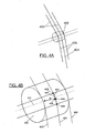
Figures 4A and 4B show the generation of an auxiliary theoretical cylinder, within the process of defining the values of the control points. -
Figures 5A, 5B, 5C, 5D, 5E and 5F show the measuring stage of the point cloud in the determined control points of the bodywork. - The control process of radius and style lines comprises the following stages:
- 1. Definition of values (e.g. radius values) in the control points.
- 2. Measuring process in the control points.
- 3. Radius and position calculation process.
- The first stage of definition of values in the control points in turn comprises the following stages:
- Defining the control points on the
vehicle components 101 according to the geometry and characteristics of the vehicle model, as shown as an example inFigures 1A and2A , particularly considering the transitions between different elements or parts of the bodywork (100), as shown in detail (details A and B) in the respectiveFigures 1B and2B , particularly applying the continuity criterion between twoconsecutive components 101 of the bodywork (100). Saidfigures (1A, 1B ,2A and 2B ) show the control points selected between circles (points part 101. - Creating planes: sectioning of the geometry on points defined for the later extraction of theoretical data.
Figures 3A, 3B, 3C and 3D represent with arrows, as an example, the process of sectioning of the geometry of the component (101) of the bodywork through a central cutting plane perpendicular to the bodywork at thecontrol point number 9, from which the radius of curvature R and the length of the string L of thearc 403 of its points of tangency will be obtained.Figure 3D represents the surfaces (S1, S2) of the bodywork tangent to thearc 403. - Creating auxiliary geometry, shown in
Figures 4A and 4B , through3D software for its later treatment and use in the calculation process:- Theoretical cylinder 400: a
theoretical cylinder 400, withaxis 401, is defined at the centre 402 of the arc on the section of the style line, the cylinder having a radius RT equal to the radius R of thearc 403 and being itsaxis 401 perpendicular to the central cutting plane of the section. The length of thetheoretical cylinder 400 is defined as a standard value of 3 mm. Thistheoretical cylinder 400 will be used to calculate the value of the real radius of the control points defined. - Theoretical 404 and calculation central sections: they are generated through the intersection of the central cutting plane (which is perpendicular to the curve at its defined point) with the geometry of the
part 101, defining a curve length equal to 15mm on each surface tangent to the arc plus its circular sector (that is, a total length of 30mm plus the arc length 403). The same criterion is used for the calculation section but with a length of 5mm. These sections will be used to obtain the calculation parameter to be used to obtain the search field of the real cylinder.
- Theoretical cylinder 400: a
- The central section is the section used to understand the surrounding of the surfaces tangent to the style line, besides being able to obtain therefrom the parameter needed for the later radius calculation. This section must only be used on a manual calculation process.
- The calculation section is defined in the same way as the previous one, but with a different dimension, as it is exclusively used for obtaining the calculation parameter and will be used on a calculation process using automated software (machine programming for automated calculation).
-
Theoretical auxiliary 405 or complementary sections: they are also generated by the intersection of planes and geometry, with the specific characteristic that the perpendicular cutting planes are created at 1.5mm at each side of the central cutting plane. These intersections are defined with a curve length of 7mm on the surface tangent to the arc and coinciding in their start on the tangency of the style line surface. The result is four theoreticalauxiliary sections 405. These sections will be used to optimize the position of the point cloud, obtained in a later phase, on the CAD geometry. - Theoretical points of tangency 406: they are obtained from the intersection of the central cutting plane used to create the theoretical
central section 404 and the limits of the surfaces (S1, S2) tangent to the style line. These points indicate the length (L) of thearc string 407 as well as the position of the tangencies. - Theoretical
middle point 408 of the string; it is the middle point of the points of tangency. The position of the circular sector is obtained. - Theoretical
middle point 409 of the arc: it is the central point of thearc 403 or maximum point of the peak of the style line. The position of the peak of the arc is obtained, thus being possible to observe the differences vis-à-vis the middle point of the arc. - The second relative stage of the measuring process at the control points, shown in
Figures 5A, 5B, 5C, 5D, 5E and 5F , comprises obtaining thepoint cloud 106 using coordinates measuring machines 105 (CMM). Performed with a laser scanner (contactless optical sensor based on the triangulation with structured laser light), the three-dimensional geometrical characteristics of the vehicle component is obtained at the points of interest, control points (that is, a scanning of the geometry of the real part).Figures 5A, 5B and 5C show the obtaining of the point cloud or set ofpoints 106 around thecontrol point number 9. - The third stage relating to the position and radius calculation process comprises:
- Treatment of the alignments of the measuring process: Work starts with the vehicle alignment, whose origin "0" is approximately at the centre of the differential. According to the area or element to be controlled (door, bumper, hood...), a RPS (Reference Position System) alignment thereof is created. Later, the cloud for each point will be optimized.
- Calculation process:
- 1. Calculation of auxiliary or complementary sections: Once the
point cloud 106 is obtained, the density of which will depend on the scanning speed and the parameterised step, a series of points are obtained from it projected on CAD geometry. Each group of points projected on the CAD geometry will form one of the auxiliary or complementary sections. These sections are obtained through the calculation made by the measuring software. The projected points are calculated with a 0.5mm increment between them and show thedeviations 110 existing between the point cloud (real geometry 107) and the CAD geometry (theoretical geometry 108). From the cloud point, the points contained in each search field of the element are used. The 0.5mm increment is defined to extract only a limited number of points from all those contained in the cloud. - 2. Point cloud optimization: In order to place the point cloud in the best possible position with respect to the CAD geometry and eliminate possible calculation errors, an optimization of the position thereof is carried out. It is carried out unlocking degrees of freedom depending on the angle formed by the cylinder axis and the reference axes (Y, Z) of the vehicle. For example, the cylinder axis angle is 90° with respect to axes Y-Z. The characteristics of the optimization will be to allow translations in the calculation on axes Y-Z and rotation around axis X.
- 3. Calculation of central and calculation sections: Once the aforementioned optimization has been performed, the deviations of the central and calculation sections are calculated, obtaining their points compared on CAD data and with a 0.1mm increment between them. From the point cloud, the points contained in each search field of the element are used and this process is an internal process of the measuring software. The 0.5mm increment is defined to extract only a limited number of points from all those contained in the cloud. Such a reduced increment is defined to obtain the greatest number of points within the surface of the style line, whose width ranges between approximately 1mm and 4mm. The theoretical dimensional characteristics of the surface of the style line, such as its width, are defined by the project and they are unalterable values.
- 4. Search field determination 111: After calculation of the aforementioned sections, the absolute values of the deviations of the calculation section points are calculated, both positive and negative values, and the search parameter DMAX is created which will be the highest of the aforementioned values, that is, DMAX is the highest deviations produced, in absolute value. Where RT is the radius of the theoretical cylinder, the
search field 111 of the real cylinder is determined between a cylinder with a radius RT - DMAX and a cylinder with a radius RT + DMAX. - 5. Calculation of the real cylinder: Once the maximum deviation of the calculation section has been obtained, it shall be used to calculate the radius of the real cylinder. This maximum deviation will be the search which we will apply to the cylinder, so that within this
search field 111 all points of the cloud which are within it will be captured and the real cylinder will be built with them, the radius value of said cylinder being compared to the theoretical value, thus attaining a radius deviation. - 6. Calculation of real points of tangency: Once the real cylinder has been calculated, we will also have all the points of the cloud used for building it. From them, the ends in the direction of the imaginary theoretical line will be extracted, which would form the points of tangency. In other words, those points from the ones used in the cylinder calculation which are furthest away from one another in the direction described above. These points are considered tangencies and are compared on their theoretical value, thus obtaining their dispersions.
- 7. Calculation of the real middle point of the string: With the middle point of those already obtained, the position of the string sector of each circular segment is attained.
- 8. Calculation of the real middle point of the arc (peak): In order to calculate the middle point of the arc, a point of the cloud is compared on the auxiliary CAD geometry created before. This point is defined in the end point of the surface (peak).
- 1. Calculation of auxiliary or complementary sections: Once the
- With this information we can determine if the peak of the circular segment corresponds to the position of the sector (middle point of the string), or if there exists within the segment a deformation thereof.
Claims (6)
- Control procedure of radius and style lines of motor vehicle components, characterized in that it comprises:- selecting, in a vehicle component (101) at least one control point;- in a 3D model of the vehicle component (101), for each control point, selecting the geometry of the component (101) with a perpendicular central cutting plane in the control point and obtaining the arc (403) centre (402) which goes through the control point and its radius of curvature R;- in a 3D model of the vehicle component (101), creating an auxiliary geometry comprising, for each control point, obtaining:• a theoretical cylinder (400) centred in the arc centre, with its axis perpendicular to the central cutting plane and with a radius of curvature RT equal to the radius R of the arc (403);• a theoretical central section (404) generated by the intersection of the central cutting plane with the geometry of the component (101);• four theoretical auxiliary sections (405) generated by the intersection of two cutting planes parallel to the central cutting plane, and located at each side thereof at a particular distance, with the surfaces (S1, S2) of the component which are tangent to the arc (403);• theoretical points of tangency (406), obtained as the intersection of the central cutting plane with the ends of said surfaces tangent (S1, S2) to the arc (403);- making a three-dimensional scanning of the component (101) around each control point, obtaining a set of measuring points (106) representing the three-dimensional geometrical characteristics of the component (101);- calculating the existing deviations (101) between the auxiliary sections of the real geometry (107) obtained from the set of measuring points (106) and the theoretical auxiliary sections (405);- calculating the existing deviations between the central section of the real geometry (107) obtained from the set of measuring points (106) and the theoretical central section (404);- determining, from the previously-obtained deviations, a search field (111) in which the search for a real cylinder will be performed;- obtaining, from the set of measuring points (106) within the search field, the real cylinder and the deviation of its radius vis-à-vis the radius RT of the theoretical cylinder (400);- obtaining, from the real cylinder and the set of measuring points (106), the real points of tangency and the deviation thereof vis-à-vis the theoretical points of tangency (406).
- Control procedure for radius and style lines of motor vehicle components according to claim 1, additionally comprising:- in the 3D model of the vehicle, obtaining for each control point:• a theoretical middle point (408) of the string, being the middle point of the theoretical points of tangency (406);• a theoretical middle point (409) of the arc; being the central point of the arc (403);- obtaining, from the real points of tangency, the real middle point of the string;- obtaining, from the real cylinder and the set of measuring points (106), the real middle point of the arc and the deviation thereof vis-à-vis the theoretical middle point (409).
- Control procedure of radius and style lines of motor vehicle components according to any of the preceding claims, wherein the three-dimensional scanning of the component (101) is performed by means of a laser scanner (105).
- Control procedure of radius and style lines of motor vehicle components according to any of the preceding claims, wherein the search field (111) is determined as a cylindrical volume defined between a cylinder with a radius RT-DMAX and a cylinder with radius RT+DMAX, where DMAX is the greatest deviation in absolute value produced between the central section of the real geometry (107) and the theoretical central section (404).
- Control procedure of radius and style lines of motor vehicle components according to any of the preceding claims, additionally comprising an optimization stage of the set of measuring points (106), in which said set of points is placed in an optimal position with respect to the geometry of the 3D model of the vehicle through the unlocking of degrees of freedom according to the angle formed by the cylinder axis and the reference axes of the vehicle.
- Control procedure of radius and style lines of motor vehicle components according to any of the preceding claims, wherein the vehicle component (101) is selected between the following: a bodywork element (100); an interior vehicle component.
Priority Applications (5)
| Application Number | Priority Date | Filing Date | Title |
|---|---|---|---|
| EP10380144A EP2453375B1 (en) | 2010-11-30 | 2010-11-30 | Control procedure of style line of motor vehicle components |
| PT103801445T PT2453375E (en) | 2010-11-30 | 2010-11-30 | Control procedure of style line of motor vehicle components |
| PL10380144T PL2453375T3 (en) | 2010-11-30 | 2010-11-30 | Control procedure of style line of motor vehicle components |
| ES10380144T ES2397268T3 (en) | 2010-11-30 | 2010-11-30 | Procedure of control of radios and lines of style of components of motor vehicles |
| PCT/ES2011/070821 WO2012072845A1 (en) | 2010-11-30 | 2011-11-25 | Procedure for control of the radii and style lines of automobile components |
Applications Claiming Priority (1)
| Application Number | Priority Date | Filing Date | Title |
|---|---|---|---|
| EP10380144A EP2453375B1 (en) | 2010-11-30 | 2010-11-30 | Control procedure of style line of motor vehicle components |
Publications (2)
| Publication Number | Publication Date |
|---|---|
| EP2453375A1 true EP2453375A1 (en) | 2012-05-16 |
| EP2453375B1 EP2453375B1 (en) | 2012-10-10 |
Family
ID=43844538
Family Applications (1)
| Application Number | Title | Priority Date | Filing Date |
|---|---|---|---|
| EP10380144A Not-in-force EP2453375B1 (en) | 2010-11-30 | 2010-11-30 | Control procedure of style line of motor vehicle components |
Country Status (5)
| Country | Link |
|---|---|
| EP (1) | EP2453375B1 (en) |
| ES (1) | ES2397268T3 (en) |
| PL (1) | PL2453375T3 (en) |
| PT (1) | PT2453375E (en) |
| WO (1) | WO2012072845A1 (en) |
Cited By (2)
| Publication number | Priority date | Publication date | Assignee | Title |
|---|---|---|---|---|
| CN113761657A (en) * | 2021-09-01 | 2021-12-07 | 沪东中华造船(集团)有限公司 | Lofting method for pipe column connection intersecting line |
| CN115130213A (en) * | 2022-06-23 | 2022-09-30 | 岚图汽车科技有限公司 | Method and device for acquiring vehicle section and electronic equipment |
Families Citing this family (1)
| Publication number | Priority date | Publication date | Assignee | Title |
|---|---|---|---|---|
| CN110348163B (en) * | 2019-07-19 | 2022-09-13 | 合肥工业大学 | Fitting method for continuous tangent circular arc of tire pattern boundary |
Citations (3)
| Publication number | Priority date | Publication date | Assignee | Title |
|---|---|---|---|---|
| WO1996034251A1 (en) * | 1995-04-28 | 1996-10-31 | Vision Systems Oy | A method and device for measuring the characteristic quantities of a log |
| EP1785940A2 (en) * | 2005-11-15 | 2007-05-16 | General Electric Company | Computer-implemented techniques and system for characterizing geometric parameters of an edge break in a machined part |
| US20100053191A1 (en) * | 2008-09-03 | 2010-03-04 | Hong Fu Jin Precision Industry (Shenzhen) Co., Ltd. | System and method for computing and displaying a roundness error of an object |
-
2010
- 2010-11-30 PL PL10380144T patent/PL2453375T3/en unknown
- 2010-11-30 PT PT103801445T patent/PT2453375E/en unknown
- 2010-11-30 ES ES10380144T patent/ES2397268T3/en active Active
- 2010-11-30 EP EP10380144A patent/EP2453375B1/en not_active Not-in-force
-
2011
- 2011-11-25 WO PCT/ES2011/070821 patent/WO2012072845A1/en not_active Ceased
Patent Citations (3)
| Publication number | Priority date | Publication date | Assignee | Title |
|---|---|---|---|---|
| WO1996034251A1 (en) * | 1995-04-28 | 1996-10-31 | Vision Systems Oy | A method and device for measuring the characteristic quantities of a log |
| EP1785940A2 (en) * | 2005-11-15 | 2007-05-16 | General Electric Company | Computer-implemented techniques and system for characterizing geometric parameters of an edge break in a machined part |
| US20100053191A1 (en) * | 2008-09-03 | 2010-03-04 | Hong Fu Jin Precision Industry (Shenzhen) Co., Ltd. | System and method for computing and displaying a roundness error of an object |
Cited By (2)
| Publication number | Priority date | Publication date | Assignee | Title |
|---|---|---|---|---|
| CN113761657A (en) * | 2021-09-01 | 2021-12-07 | 沪东中华造船(集团)有限公司 | Lofting method for pipe column connection intersecting line |
| CN115130213A (en) * | 2022-06-23 | 2022-09-30 | 岚图汽车科技有限公司 | Method and device for acquiring vehicle section and electronic equipment |
Also Published As
| Publication number | Publication date |
|---|---|
| PT2453375E (en) | 2013-01-24 |
| ES2397268T3 (en) | 2013-03-05 |
| WO2012072845A1 (en) | 2012-06-07 |
| EP2453375B1 (en) | 2012-10-10 |
| PL2453375T3 (en) | 2013-05-31 |
Similar Documents
| Publication | Publication Date | Title |
|---|---|---|
| CN102473008B (en) | Automatic programming device and method | |
| CN102473009B (en) | Automatic programming device and method | |
| JP5100249B2 (en) | Information processing method, information processing apparatus, and program | |
| CN103760821A (en) | Complex casting machining process datum determination method | |
| US10434555B2 (en) | Metrology Assisted Part Forming System and Method | |
| RU2579408C2 (en) | Automation of pipe-forming press with light source for measurement of pipe internal outline | |
| US10884390B2 (en) | Optimized control of a metal-cutting machine tool | |
| Gaspar et al. | Integrated construction and simulation of tool paths for milling dental crowns and bridges | |
| EP2453375B1 (en) | Control procedure of style line of motor vehicle components | |
| US11151735B1 (en) | Deformation processing support system and deformation processing support method | |
| US8594831B2 (en) | Automatic programming method and automatic programming device | |
| Barnfather et al. | Efficient compensation of dimensional errors in robotic machining using imperfect point cloud part inspection data | |
| US20170343982A1 (en) | Method for machining a workpiece by means of a chip-removing tool on a numerically-controlled machine tool | |
| CN120597426B (en) | A marine propeller stamping production control method and system | |
| CN106981088A (en) | Use the method for objective plane during 3-D scanning technical limit spacing automatic plastering | |
| Liu et al. | Direct 5-axis tool posture local collision-free area generation for point clouds | |
| Galanulis et al. | Optical digitizing by ATOS for press parts and tools | |
| JP6894591B2 (en) | Measurement data generator, machining program generation system, measurement data generation method | |
| CN112347585B (en) | An analytical calculation method for the contact area between ball end milling cutter and workpiece | |
| CN121468411B (en) | A method and system for adaptive abrasive jet strengthening of complex curved surfaces | |
| CN121366216B (en) | Spoke grinding track generation method based on fusion of point cloud and theoretical model | |
| JP2020190482A (en) | Shape evaluation method and shape evaluation device | |
| JP2008044025A (en) | Calculation method of uneven surface of cutting machined surface and control method of uneven surface in milling and machining | |
| Xu et al. | Robot edge milling method for large, complex curved thin-walled parts driven by measured data | |
| JP4779508B2 (en) | Bearing design system |
Legal Events
| Date | Code | Title | Description |
|---|---|---|---|
| PUAI | Public reference made under article 153(3) epc to a published international application that has entered the european phase |
Free format text: ORIGINAL CODE: 0009012 |
|
| AK | Designated contracting states |
Kind code of ref document: A1 Designated state(s): AL AT BE BG CH CY CZ DE DK EE ES FI FR GB GR HR HU IE IS IT LI LT LU LV MC MK MT NL NO PL PT RO RS SE SI SK SM TR |
|
| AX | Request for extension of the european patent |
Extension state: BA ME |
|
| 17P | Request for examination filed |
Effective date: 20120404 |
|
| GRAP | Despatch of communication of intention to grant a patent |
Free format text: ORIGINAL CODE: EPIDOSNIGR1 |
|
| GRAS | Grant fee paid |
Free format text: ORIGINAL CODE: EPIDOSNIGR3 |
|
| GRAA | (expected) grant |
Free format text: ORIGINAL CODE: 0009210 |
|
| AK | Designated contracting states |
Kind code of ref document: B1 Designated state(s): AL AT BE BG CH CY CZ DE DK EE ES FI FR GB GR HR HU IE IS IT LI LT LU LV MC MK MT NL NO PL PT RO RS SE SI SK SM TR |
|
| REG | Reference to a national code |
Ref country code: GB Ref legal event code: FG4D |
|
| REG | Reference to a national code |
Ref country code: AT Ref legal event code: REF Ref document number: 579241 Country of ref document: AT Kind code of ref document: T Effective date: 20121015 Ref country code: CH Ref legal event code: EP |
|
| REG | Reference to a national code |
Ref country code: IE Ref legal event code: FG4D |
|
| REG | Reference to a national code |
Ref country code: DE Ref legal event code: R096 Ref document number: 602010003171 Country of ref document: DE Effective date: 20121206 |
|
| REG | Reference to a national code |
Ref country code: RO Ref legal event code: EPE |
|
| REG | Reference to a national code |
Ref country code: PT Ref legal event code: SC4A Free format text: AVAILABILITY OF NATIONAL TRANSLATION Effective date: 20130109 |
|
| REG | Reference to a national code |
Ref country code: SE Ref legal event code: TRGR |
|
| REG | Reference to a national code |
Ref country code: CH Ref legal event code: NV Representative=s name: FIAMMENGHI-FIAMMENGHI, CH |
|
| REG | Reference to a national code |
Ref country code: CH Ref legal event code: NV Representative=s name: FIAMMENGHI-FIAMMENGHI, CH |
|
| PG25 | Lapsed in a contracting state [announced via postgrant information from national office to epo] |
Ref country code: SI Free format text: LAPSE BECAUSE OF FAILURE TO SUBMIT A TRANSLATION OF THE DESCRIPTION OR TO PAY THE FEE WITHIN THE PRESCRIBED TIME-LIMIT Effective date: 20121010 |
|
| REG | Reference to a national code |
Ref country code: ES Ref legal event code: FG2A Ref document number: 2397268 Country of ref document: ES Kind code of ref document: T3 Effective date: 20130305 |
|
| REG | Reference to a national code |
Ref country code: NL Ref legal event code: VDEP Effective date: 20121010 |
|
| REG | Reference to a national code |
Ref country code: LT Ref legal event code: MG4D |
|
| REG | Reference to a national code |
Ref country code: SK Ref legal event code: T3 Ref document number: E 13239 Country of ref document: SK |
|
| PG25 | Lapsed in a contracting state [announced via postgrant information from national office to epo] |
Ref country code: NL Free format text: LAPSE BECAUSE OF FAILURE TO SUBMIT A TRANSLATION OF THE DESCRIPTION OR TO PAY THE FEE WITHIN THE PRESCRIBED TIME-LIMIT Effective date: 20121010 Ref country code: HR Free format text: LAPSE BECAUSE OF FAILURE TO SUBMIT A TRANSLATION OF THE DESCRIPTION OR TO PAY THE FEE WITHIN THE PRESCRIBED TIME-LIMIT Effective date: 20121010 Ref country code: NO Free format text: LAPSE BECAUSE OF FAILURE TO SUBMIT A TRANSLATION OF THE DESCRIPTION OR TO PAY THE FEE WITHIN THE PRESCRIBED TIME-LIMIT Effective date: 20130110 Ref country code: FI Free format text: LAPSE BECAUSE OF FAILURE TO SUBMIT A TRANSLATION OF THE DESCRIPTION OR TO PAY THE FEE WITHIN THE PRESCRIBED TIME-LIMIT Effective date: 20121010 Ref country code: LT Free format text: LAPSE BECAUSE OF FAILURE TO SUBMIT A TRANSLATION OF THE DESCRIPTION OR TO PAY THE FEE WITHIN THE PRESCRIBED TIME-LIMIT Effective date: 20121010 Ref country code: IS Free format text: LAPSE BECAUSE OF FAILURE TO SUBMIT A TRANSLATION OF THE DESCRIPTION OR TO PAY THE FEE WITHIN THE PRESCRIBED TIME-LIMIT Effective date: 20130210 |
|
| PGFP | Annual fee paid to national office [announced via postgrant information from national office to epo] |
Ref country code: RO Payment date: 20130108 Year of fee payment: 3 Ref country code: SE Payment date: 20130109 Year of fee payment: 3 Ref country code: CZ Payment date: 20130124 Year of fee payment: 3 |
|
| PG25 | Lapsed in a contracting state [announced via postgrant information from national office to epo] |
Ref country code: BE Free format text: LAPSE BECAUSE OF FAILURE TO SUBMIT A TRANSLATION OF THE DESCRIPTION OR TO PAY THE FEE WITHIN THE PRESCRIBED TIME-LIMIT Effective date: 20121010 Ref country code: LV Free format text: LAPSE BECAUSE OF FAILURE TO SUBMIT A TRANSLATION OF THE DESCRIPTION OR TO PAY THE FEE WITHIN THE PRESCRIBED TIME-LIMIT Effective date: 20121010 Ref country code: GR Free format text: LAPSE BECAUSE OF FAILURE TO SUBMIT A TRANSLATION OF THE DESCRIPTION OR TO PAY THE FEE WITHIN THE PRESCRIBED TIME-LIMIT Effective date: 20130111 |
|
| PGFP | Annual fee paid to national office [announced via postgrant information from national office to epo] |
Ref country code: SK Payment date: 20130124 Year of fee payment: 3 Ref country code: PL Payment date: 20130109 Year of fee payment: 3 |
|
| REG | Reference to a national code |
Ref country code: PL Ref legal event code: T3 |
|
| PGFP | Annual fee paid to national office [announced via postgrant information from national office to epo] |
Ref country code: PT Payment date: 20130122 Year of fee payment: 3 |
|
| PG25 | Lapsed in a contracting state [announced via postgrant information from national office to epo] |
Ref country code: EE Free format text: LAPSE BECAUSE OF FAILURE TO SUBMIT A TRANSLATION OF THE DESCRIPTION OR TO PAY THE FEE WITHIN THE PRESCRIBED TIME-LIMIT Effective date: 20121010 Ref country code: BG Free format text: LAPSE BECAUSE OF FAILURE TO SUBMIT A TRANSLATION OF THE DESCRIPTION OR TO PAY THE FEE WITHIN THE PRESCRIBED TIME-LIMIT Effective date: 20130110 Ref country code: DK Free format text: LAPSE BECAUSE OF FAILURE TO SUBMIT A TRANSLATION OF THE DESCRIPTION OR TO PAY THE FEE WITHIN THE PRESCRIBED TIME-LIMIT Effective date: 20121010 Ref country code: RS Free format text: LAPSE BECAUSE OF FAILURE TO SUBMIT A TRANSLATION OF THE DESCRIPTION OR TO PAY THE FEE WITHIN THE PRESCRIBED TIME-LIMIT Effective date: 20121010 |
|
| PLBE | No opposition filed within time limit |
Free format text: ORIGINAL CODE: 0009261 |
|
| STAA | Information on the status of an ep patent application or granted ep patent |
Free format text: STATUS: NO OPPOSITION FILED WITHIN TIME LIMIT |
|
| REG | Reference to a national code |
Ref country code: IE Ref legal event code: MM4A |
|
| 26N | No opposition filed |
Effective date: 20130711 |
|
| PG25 | Lapsed in a contracting state [announced via postgrant information from national office to epo] |
Ref country code: IE Free format text: LAPSE BECAUSE OF NON-PAYMENT OF DUE FEES Effective date: 20121130 |
|
| REG | Reference to a national code |
Ref country code: DE Ref legal event code: R097 Ref document number: 602010003171 Country of ref document: DE Effective date: 20130711 |
|
| PG25 | Lapsed in a contracting state [announced via postgrant information from national office to epo] |
Ref country code: MT Free format text: LAPSE BECAUSE OF FAILURE TO SUBMIT A TRANSLATION OF THE DESCRIPTION OR TO PAY THE FEE WITHIN THE PRESCRIBED TIME-LIMIT Effective date: 20121010 Ref country code: CY Free format text: LAPSE BECAUSE OF FAILURE TO SUBMIT A TRANSLATION OF THE DESCRIPTION OR TO PAY THE FEE WITHIN THE PRESCRIBED TIME-LIMIT Effective date: 20121010 Ref country code: AL Free format text: LAPSE BECAUSE OF FAILURE TO SUBMIT A TRANSLATION OF THE DESCRIPTION OR TO PAY THE FEE WITHIN THE PRESCRIBED TIME-LIMIT Effective date: 20121010 |
|
| PG25 | Lapsed in a contracting state [announced via postgrant information from national office to epo] |
Ref country code: MC Free format text: LAPSE BECAUSE OF NON-PAYMENT OF DUE FEES Effective date: 20121130 |
|
| PG25 | Lapsed in a contracting state [announced via postgrant information from national office to epo] |
Ref country code: LU Free format text: LAPSE BECAUSE OF NON-PAYMENT OF DUE FEES Effective date: 20121130 Ref country code: SM Free format text: LAPSE BECAUSE OF FAILURE TO SUBMIT A TRANSLATION OF THE DESCRIPTION OR TO PAY THE FEE WITHIN THE PRESCRIBED TIME-LIMIT Effective date: 20121010 |
|
| REG | Reference to a national code |
Ref country code: SE Ref legal event code: EUG |
|
| PG25 | Lapsed in a contracting state [announced via postgrant information from national office to epo] |
Ref country code: HU Free format text: LAPSE BECAUSE OF FAILURE TO SUBMIT A TRANSLATION OF THE DESCRIPTION OR TO PAY THE FEE WITHIN THE PRESCRIBED TIME-LIMIT Effective date: 20101130 |
|
| REG | Reference to a national code |
Ref country code: SK Ref legal event code: MM4A Ref document number: E 13239 Country of ref document: SK Effective date: 20131130 |
|
| PG25 | Lapsed in a contracting state [announced via postgrant information from national office to epo] |
Ref country code: SE Free format text: LAPSE BECAUSE OF NON-PAYMENT OF DUE FEES Effective date: 20131201 Ref country code: SK Free format text: LAPSE BECAUSE OF NON-PAYMENT OF DUE FEES Effective date: 20131130 Ref country code: CZ Free format text: LAPSE BECAUSE OF NON-PAYMENT OF DUE FEES Effective date: 20131130 Ref country code: RO Free format text: LAPSE BECAUSE OF NON-PAYMENT OF DUE FEES Effective date: 20131130 |
|
| REG | Reference to a national code |
Ref country code: PT Ref legal event code: MM4A Free format text: LAPSE DUE TO NON-PAYMENT OF FEES Effective date: 20140901 |
|
| PG25 | Lapsed in a contracting state [announced via postgrant information from national office to epo] |
Ref country code: PT Free format text: LAPSE BECAUSE OF NON-PAYMENT OF DUE FEES Effective date: 20140901 |
|
| PG25 | Lapsed in a contracting state [announced via postgrant information from national office to epo] |
Ref country code: PL Free format text: LAPSE BECAUSE OF NON-PAYMENT OF DUE FEES Effective date: 20131130 |
|
| REG | Reference to a national code |
Ref country code: PL Ref legal event code: LAPE |
|
| REG | Reference to a national code |
Ref country code: CH Ref legal event code: PL |
|
| PG25 | Lapsed in a contracting state [announced via postgrant information from national office to epo] |
Ref country code: CH Free format text: LAPSE BECAUSE OF NON-PAYMENT OF DUE FEES Effective date: 20141130 Ref country code: MK Free format text: LAPSE BECAUSE OF FAILURE TO SUBMIT A TRANSLATION OF THE DESCRIPTION OR TO PAY THE FEE WITHIN THE PRESCRIBED TIME-LIMIT Effective date: 20121010 Ref country code: LI Free format text: LAPSE BECAUSE OF NON-PAYMENT OF DUE FEES Effective date: 20141130 |
|
| REG | Reference to a national code |
Ref country code: FR Ref legal event code: PLFP Year of fee payment: 6 |
|
| PG25 | Lapsed in a contracting state [announced via postgrant information from national office to epo] |
Ref country code: TR Free format text: THE PATENT HAS BEEN ANNULLED BY A DECISION OF A NATIONAL AUTHORITY Effective date: 20121010 |
|
| REG | Reference to a national code |
Ref country code: FR Ref legal event code: PLFP Year of fee payment: 7 |
|
| REG | Reference to a national code |
Ref country code: AT Ref legal event code: MM01 Ref document number: 579241 Country of ref document: AT Kind code of ref document: T Effective date: 20151130 |
|
| PGFP | Annual fee paid to national office [announced via postgrant information from national office to epo] |
Ref country code: GB Payment date: 20161130 Year of fee payment: 7 |
|
| PG25 | Lapsed in a contracting state [announced via postgrant information from national office to epo] |
Ref country code: AT Free format text: LAPSE BECAUSE OF NON-PAYMENT OF DUE FEES Effective date: 20151130 |
|
| PGFP | Annual fee paid to national office [announced via postgrant information from national office to epo] |
Ref country code: ES Payment date: 20161223 Year of fee payment: 7 Ref country code: IT Payment date: 20161129 Year of fee payment: 7 |
|
| REG | Reference to a national code |
Ref country code: FR Ref legal event code: PLFP Year of fee payment: 8 |
|
| GBPC | Gb: european patent ceased through non-payment of renewal fee |
Effective date: 20171130 |
|
| PG25 | Lapsed in a contracting state [announced via postgrant information from national office to epo] |
Ref country code: IT Free format text: LAPSE BECAUSE OF NON-PAYMENT OF DUE FEES Effective date: 20171130 |
|
| PG25 | Lapsed in a contracting state [announced via postgrant information from national office to epo] |
Ref country code: GB Free format text: LAPSE BECAUSE OF NON-PAYMENT OF DUE FEES Effective date: 20171130 |
|
| PG25 | Lapsed in a contracting state [announced via postgrant information from national office to epo] |
Ref country code: ES Free format text: LAPSE BECAUSE OF NON-PAYMENT OF DUE FEES Effective date: 20171201 |
|
| REG | Reference to a national code |
Ref country code: DE Ref legal event code: R079 Ref document number: 602010003171 Country of ref document: DE Free format text: PREVIOUS MAIN CLASS: G06F0017500000 Ipc: G06F0030000000 |
|
| PGFP | Annual fee paid to national office [announced via postgrant information from national office to epo] |
Ref country code: FR Payment date: 20201126 Year of fee payment: 11 |
|
| REG | Reference to a national code |
Ref country code: DE Ref legal event code: R082 Ref document number: 602010003171 Country of ref document: DE Representative=s name: KILBURN & STRODE LLP, NL |
|
| PGFP | Annual fee paid to national office [announced via postgrant information from national office to epo] |
Ref country code: DE Payment date: 20210128 Year of fee payment: 11 |
|
| REG | Reference to a national code |
Ref country code: DE Ref legal event code: R119 Ref document number: 602010003171 Country of ref document: DE |
|
| PG25 | Lapsed in a contracting state [announced via postgrant information from national office to epo] |
Ref country code: DE Free format text: LAPSE BECAUSE OF NON-PAYMENT OF DUE FEES Effective date: 20220601 |
|
| PG25 | Lapsed in a contracting state [announced via postgrant information from national office to epo] |
Ref country code: FR Free format text: LAPSE BECAUSE OF NON-PAYMENT OF DUE FEES Effective date: 20211130 |