EP2453247A1 - Partial discharge coupler for application on high voltage generator bus works - Google Patents
Partial discharge coupler for application on high voltage generator bus works Download PDFInfo
- Publication number
- EP2453247A1 EP2453247A1 EP12152310A EP12152310A EP2453247A1 EP 2453247 A1 EP2453247 A1 EP 2453247A1 EP 12152310 A EP12152310 A EP 12152310A EP 12152310 A EP12152310 A EP 12152310A EP 2453247 A1 EP2453247 A1 EP 2453247A1
- Authority
- EP
- European Patent Office
- Prior art keywords
- partial discharge
- component
- differential amplifier
- fuse
- high voltage
- Prior art date
- Legal status (The legal status is an assumption and is not a legal conclusion. Google has not performed a legal analysis and makes no representation as to the accuracy of the status listed.)
- Granted
Links
Images


Classifications
-
- G—PHYSICS
- G01—MEASURING; TESTING
- G01R—MEASURING ELECTRIC VARIABLES; MEASURING MAGNETIC VARIABLES
- G01R31/00—Arrangements for testing electric properties; Arrangements for locating electric faults; Arrangements for electrical testing characterised by what is being tested not provided for elsewhere
- G01R31/12—Testing dielectric strength or breakdown voltage ; Testing or monitoring effectiveness or level of insulation, e.g. of a cable or of an apparatus, for example using partial discharge measurements; Electrostatic testing
- G01R31/1227—Testing dielectric strength or breakdown voltage ; Testing or monitoring effectiveness or level of insulation, e.g. of a cable or of an apparatus, for example using partial discharge measurements; Electrostatic testing of components, parts or materials
- G01R31/1263—Testing dielectric strength or breakdown voltage ; Testing or monitoring effectiveness or level of insulation, e.g. of a cable or of an apparatus, for example using partial discharge measurements; Electrostatic testing of components, parts or materials of solid or fluid materials, e.g. insulation films, bulk material; of semiconductors or LV electronic components or parts; of cable, line or wire insulation
- G01R31/1272—Testing dielectric strength or breakdown voltage ; Testing or monitoring effectiveness or level of insulation, e.g. of a cable or of an apparatus, for example using partial discharge measurements; Electrostatic testing of components, parts or materials of solid or fluid materials, e.g. insulation films, bulk material; of semiconductors or LV electronic components or parts; of cable, line or wire insulation of cable, line or wire insulation, e.g. using partial discharge measurements
Definitions
- the present invention relates in general to partial discharge couplers, and in particular, to partial discharge couplers for use with high voltage generator bus works.
- High voltage electrical applications such as high-voltage dynamoelectric machines, electrical generators in power plants, etc.
- a breakdown of the insulation in such a high voltage electrical application can have significant consequences, including potential damage to the electrical device and/or components electrically coupled to the device.
- proactive measures may be utilized to predict an impending breakdown.
- One such proactive strategy is to evaluate an indicator of the integrity of a high voltage electrical device by measuring partial discharges.
- Partial discharges are small electrical sparks that occur within the insulation of electrical devices, such as windings in motors and generators. Partial discharges may also occur within the insulation of other electrical devices that are subject to high voltages, such as transformers and cables. More particularly, a partial discharge represents a localized breakdown of the electrical insulation of a component under high voltage stress. For example, localized breakdowns may occur in small air pockets within the electrical insulation. These electrical breakdowns exhibit themselves as high frequency electric current pulses that flow through the air pockets. Partial discharge measurements can be used as a predictor of reliability of the insulation of an electrical conductor, and thus a need for maintenance of the electrical device.
- passive partial discharge couplers are provided on each isophase bus connecting a generator to a corresponding step up transformer. Partial discharge pulses detected by the partial discharge couplers are carried to testing equipment along corresponding signal lines for measurement and subsequent analysis.
- a partial discharge coupler for detecting partial discharges in a conductor carrying a high voltage alternating current signal.
- the partial discharge coupler includes a frequency dependent network, a differential amplifier and a frequency selective coupling component that couples the differential amplifier to the frequency dependent network.
- the frequency dependent network may include a first filter component, a fuse component and a load component.
- the first filter component is configured to filter the high voltage, low frequency, alternating current signal carried by the conductor from the load component and is further configured to pass high frequency partial discharge pulse signals to the load component when the partial discharge coupler is installed between the conductor and a ground.
- the fuse component is configured to provide overload protection to the partial discharge coupler if a signal through the fuse component exceeds a predetermined fuse condition.
- the fuse component may comprise a fast clearing fuse that employs sub-60 Hz cycle operation to provide disconnect of the partial discharge coupler from the power bus if the predetermined fuse condition is exceeded.
- the load component defines a first node and a second node.
- the first node is connected to the remainder of the network and the second node is coupled to ground when the frequency dependent network is installed between the conductor and the ground.
- the differential amplifier includes a first differential input, a second differential input and an output.
- the frequency selective coupling component is coupled in series between the first differential input of the differential amplifier and the first node of the load component, and is configured to pass high frequency partial discharge signals to the differential amplifier, and to filter low frequency alternating current signals from the differential amplifier.
- the second differential input of the differential amplifier is coupled to the second node of the load component, and the output of the differential amplifier is configured to provide an output that is isolated from the first ground connection for communicating detected partial discharge signals to partial discharge test equipment.
- a partial discharge coupler for detecting partial discharges in a conductor carrying a high voltage alternating current signal.
- the partial discharge coupler includes a frequency dependent network having a first filter component, a fuse component and a load component, connected in series with each other.
- the first filter component is configured to filter the high voltage, low frequency alternating current signal carried by the conductor from the load component and to pass high frequency partial discharge pulse signals to the load component when the partial discharge coupler is installed between the conductor and a ground.
- the fuse component is configured to provide overload protection to the partial discharge coupler if a signal through the fuse component exceeds a predetermined fuse condition.
- the load component defines a first node and a second node. The first node is connected to the remainder of the series network and the second node is coupled to the ground when the frequency dependent network is installed between the conductor and the ground.
- the partial discharge coupler further includes a connector socket having a first socket connection, a second socket connection and a shorting connection.
- the shorting connection electrically couples (shunts) the first socket connection to the second socket connection when no corresponding plug is inserted into the socket connection.
- the shorting connection also electrically disconnects the first socket connection from the second socket connection when a corresponding plug is connected to the connector socket.
- a frequency selective coupling component is coupled in series between the first socket connection of the connector socket and the first node of the load component.
- the second socket connection is coupled to the second node of the load component.
- the partial discharge coupler may further include a differential amplifier having a first differential input, a second differential input and an output.
- the output of the differential amplifier is typically communicated to partial discharge analysis equipment and is configured to provide an output that is isolated from the ground connection of the frequency dependent network.
- a plug is coupled to the differential amplifier that can be selectively plugged into and removed from connection with the connector socket, such that when the plug is connected to the connector socket, the first differential input of the differential amplifier is coupled to the frequency dependent coupling component via the first socket connection and the second differential input of the differential amplifier is coupled to the second node of the load component via the second socket connection.
- the differential amplifier may be selectively attached to, and removed from the frequency dependent network via the plug and corresponding connector socket. Moreover, either the differential amplifier and/or shunt is electrically connected (in place) across the connector socket, depending upon whether or not the plug is mated with its corresponding connector socket. As such, the frequency selective coupling component is not left in an electrically open circuit state.
- a partial discharge coupling system for coupling an electrical generator having at least one bus bar that carries a high voltage, low frequency alternating current signal to partial discharge testing equipment.
- the system includes at least two partial discharge couplers associated with each bus bar that are spaced from each other by a predetermined distance.
- Each partial discharge coupler includes a frequency dependent network for installation between the associated bus bar and a ground, including a first filter component, a fuse component and a load component.
- the first filter component filters low frequency signals from the load component and passes high frequency partial discharge pulse signals to the load component.
- the load component defines a first node and a second node.
- each partial discharge coupler includes a differential amplifier having a first differential input, a second differential input and an output that is provided with respect to a reference that is isolated from the ground coupled to the load component.
- a frequency selective coupling component is coupled in series between the first differential input of the differential amplifier and the first node of the load component.
- the second differential input of the differential amplifier is coupled to the second node of the load component.
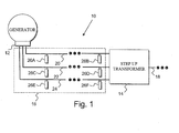
- a power plant system 10 includes in general, an electrical generator, e.g., a turbine generator 12 that is electrically coupled to a step-up transformer 14 by a generator bus works 16.
- the step-up transformer 16 is further coupled to downstream power lines 18 for delivering electrical power outside of the power plant system 10.
- the generator bus works 16 typically includes one or more electrically insulated isophase buses.
- the generator bus works 16 illustrated in Fig. 1 is implemented as three isophase buses, including a first isophase bus 20, a second isophase bus 22 and a third isophase bus 24.
- Each isophase bus 20, 22 and 24 comprises a conductor that carries a high voltage alternating current signal.
- each isophase bus 20, 22 and 24 conducts a high voltage, e.g., approximately 5 Kilovolts to approximately 30 Kilovolts, 60 Hz signal from the generator 12 to the step-up transformer 14.
- the high voltage alternating current signal carried by each of the isophase buses 20, 22 and 24 is 120 degrees out of phase with the signals carried by the other isophase buses.
- Each isophase bus 20, 22 and 24 comprises a conductor that is electrically insulated from each other using a suitable insulator layer.
- each isophase bus may comprise a large internal current carrying bus conductor that is suspended in air by porcelain supports.
- the porcelain supports are mounted to the inner surface of a grounded cover/shield such as an outer cylindrical member.
- the large air gap between the center bus conductor and outer grounded cover provides electrical insulation.
- Partial discharge can occur within this bus work.
- partial discharges are more problematic in the generator 12 and step-up transformer 14.
- partial discharges such as small sparks can occur in the insulation around the generator and step-up transformer winding e.g., via localized breakdowns in small air pockets within the electrical insulation.
- These partial discharges do not propagate completely from phase to phase or phase to ground. Therefore, measurement and analysis of these partial discharges can provide an early warning of insulation failures in high voltage electrical devices.
- partial discharge couplers are provided, which are designated generally by the reference numeral 26.
- the partial discharge couplers 26 are capable of detecting partial discharge pulse information in the generator 12, step-up transformer 14 and/or generator bus works 16. The detected partial discharge pulse information is then conveyed to corresponding testing and analysis equipment (not shown in Fig. 1 ).
- Fig. 1 illustrates two partial discharge couplers 26A, 26B that are spaced apart from each other and are coupled to the first isophase bus 20.
- Two partial discharge couplers 26C, 26D are spaced apart from each other and are coupled to the second isophase bus 22.
- two partial discharge couplers 26E, 26F are spaced apart from each other and are coupled to the third isophase bus 24.
- the partial discharge couplers 26 are illustrated as being coupled to the generator bus works 16 in Fig. 1 , such partial discharge couplers 26 may be utilized to capture partial discharge pulse information for any number of alternative high voltage electrical devices.
- the partial discharge coupler 26 comprises a frequency dependent network 30 that may be connected between an electrical device, e.g., an isophase bus bar such as one of the isophase bus bars 20, 22, 24 discussed with reference to Fig. 1 , and a first ground reference 32, e.g., an earth ground.
- a coupling component 34 couples the frequency dependent network 30 to an amplifier circuit 36.
- the partial discharge coupler 26 also provides an output 38 from the amplifier circuit 36 that may be coupled to test equipment 40, e.g., a partial discharge analyzer or other suitable equipment for analyzing partial discharge pulses.
- the isophase bus outer cylindrical shield is typically earth grounded.
- the partial discharge coupler 26 may be installed within an extension, i.e., a modification, of the isophase bus outer cylindrical shield, which is configured to insure proper high voltage isolation of the inner bus conductor.
- the illustrated partial discharge coupler 26 includes a frequency dependent network 30 having a first filter component 42, a fuse component 44 and a load component 46.
- the frequency dependent network 30 filters the high voltage alternating current from the test equipment 40 ( Fig. 2 ), and detects partial discharge pulses, which are communicated to the test equipment 40 as will be described in greater detail herein.
- the first filter component 42 is configured to filter the high voltage, low frequency alternating current signal carried by the conductor of a connected electrical device from the load component 46 when the partial discharge coupler 26 is installed between the conductor and a ground, e.g., an isophase bus 20, 22, 24 and the earth ground 32.
- the first filter component 42 is configured to pass detected high frequency partial discharge pulse signals to the load component 46, when the partial discharge coupler 26 is installed between the conductor and the ground.
- the first filter component 42 may be implemented, for example, using one or more capacitors that are configured to withstand the high voltage stress of an associated electrical device to which the partial discharge coupler 26 is attached, e.g., an isophase bus bar, which may be carrying thousands of volts.
- the capacitor may comprise any suitable material, such as glass/ceramic material(s), polymer films, etc., and may be cylindrical, puck-shaped, etc.
- the capacitor implementing the first filter component 42 is also referred to herein as an isolation capacitor.
- the isolation capacitor designates the interaction of the capacitor with the load component 46 to filter the high voltage alternating current signal carried by the conductor, .e.g., of the signal carried by the isophase bus 20, 22 and 24 from the load component 46 and to pass the high frequency partial discharge pulses to the load component 46 with minimal attenuation.
- a capacitor having the ability to withstand the stress of a voltage up to approximately 5 Kilovolts to approximately 30 Kilovolts may be required.
- the capacitor should also be capable of passing partial discharge pulses, which may comprise high frequency transient signals.
- the first filter component 42 e.g., a first capacitor
- the first filter component 42 is under constant high voltage stress by virtue of being coupled at one end to the high voltage alternating current signal carried by the conductor of the isophase bus 20, 22 or 24 in the exemplary arrangement of Fig. 1 .
- This exposure to high voltage stress causes the capacitor to age.
- the frequency dependent network 30 includes a fuse component 44 that is provided to protect against potential damage due to component failure of the first filter component 42.
- the fuse component 44 is configured to provide overload protection to the high voltage electrical application, the partial discharge coupler 26 and/or downstream test equipment 40 if a signal through the fuse component 44 exceeds a predetermined fuse condition, e.g., exceeds a predetermined current as may occur should the first filter component fail.
- the fuse component 44 may isolate the partial discharge coupler 26 from the conductor of the attached electrical device in the event of a failure of the first filter component 42, e.g., a capacitor failure, and thereby limit the capacitor fault or short circuit current that might otherwise form a conductive path to ground, from causing damage to system components.
- the fuse component 44 should also be capable of passing high frequency transient signals with minimal attenuation.
- the fuse component 44 should be configured to provide separation of the components of the partial discharge coupler 26 downstream of the first filter component 42 and fuse component 44 from the high voltage bus within a fraction of the 60 cycle line period, should the first filter component 42 fail. Moreover, the fuse component 44 should be capable of withstanding the bus voltage after the fuse has blown.
- the load component 46 defines a first node 48 and a second node 50.
- the first node 48 is connected to the remainder of the network, e.g., the fuse component 44 as shown, and the second node 50 is coupled to the ground 32 when the partial discharge coupler 26 is installed between the conductor of the electrical device and the ground.
- the load component 46 may be implemented for example, by a resistor, as will be described in greater detail herein.
- the frequency dependent network 30 is illustrated in the exemplary partial discharge coupler 26 as a series network having the fuse component serially connected between the first filter component 42 and the load component 44.
- the components may be rearranged into other configurations.
- the first filter component 42 may be relocated between the fuse component 44 and the load component 46, etc.
- Other arrangements of the components of the frequency dependent network 30 and/or alternative components may alternatively be implemented, so long as the partial discharge pulses of interest are filtered from the high voltage, alternating current signal carried by the conductor.
- the load component 46 may alternatively be replaced with other structures such as an inductor or transformer, so long as the high frequency partial discharge pulse information can be filtered from the high voltage alternating current signal carried by the conductor of the attached electrical device.
- the partial discharge coupler 26 includes an amplifier circuit 36 that is coupled to the frequency dependent network 30 by a coupling component 34.
- the amplifier circuit 36 may comprise, for example, a differential amplifier 52 having a first differential input 54, a second differential input 56 and an output 58.
- the differential nature of the inputs 54 and 56 enables the differential amplifier 52 to reject common mode signals, noise, interference, etc., from the input of the differential amplifier 52 and hence the output thereof, such as from induced 60 Hz cycles of the high voltage signal carried by the conductor of the isophase bus.
- the first differential input 54 of the differential amplifier 52 is coupled to the first node 48 of the load component 46 via the series connected coupling component 34.
- the second differential input 56 of the differential amplifier 52 is coupled to the second node 50 of the load component 46 and is thus coupled to the earth ground 32 when the partial discharge coupler 26 is suitably installed for partial discharge detection.
- the differential amplifier 52 is configured to electrically isolate the partial discharge signal removed from the isophase bus, thus providing an output 58 that is isolated from the first ground connection 32, e.g., earth ground.
- the output 58 of the differential amplifier 52 is taken relative to a second ground 62, which is different from the first ground 32.
- the output 58 of the differential amplifier 52 is electrically isolated from the signals appearing across load component 46 of the frequency dependent network 30.
- This electrically isolated output 58 may be evaluated to monitor the condition of the generator 12, step-up transformer 14, bus works 16, etc. using partial discharge testing/analysis equipment 40.
- the output 58 of the differential amplifier 52 couples to the output 38, e.g., wires that connect to test equipment 40.
- Partial discharge pulses are typically small signal level, e.g., approximately 100 millivolts in magnitude, high frequency pulses that attenuate rapidly.
- other types of pulses carried by the conductor can reach relatively large voltages, e.g., hundreds to thousands of volts.
- high voltage spikes may occur during normal unit trips when the voltage swing is within a specific region at the time of the unit trip.
- inductance/kickback can produce a high voltage spike reaching hundreds of volts.
- grid line faults may also produce high frequency pulses that can reach thousands of volts in magnitude. As such, it is possible for high voltage spikes to appear across the load component 46.
- a protection device 60 may be electrically coupled between the first and second differential inputs 54, 56 of the differential amplifier 52 for providing overload protection, e.g., to protect the differential amplifier 52 and other downstream components from damage caused by unusually large voltage spikes that may appear across the load component 46.
- the protection device 60 may be designed to electrically conduct when a low set voltage is reached. This keeps otherwise high voltage pulses from the inputs 54, 56 of the differential amplifier 52.
- the protection device 60 may be implemented, for example, as a spark gap, surge suppressor, gas discharge, etc., which offers a high impedance to low voltage partial discharge pulse signals but becomes conductive should a threshold voltage level be exceeded.
- the surge suppressor thus limits the peak voltage that can appear across the inputs 54, 56 of the differential amplifier 52, thus protecting the differential amplifier 52 from fast and high pulses sometimes experienced in a normal unit trip.
- the protection device 60 prevents spikes from appearing across the differential amplifier inputs 54, 56.
- the differential configuration of the differential amplifier 52 i.e., differential inputs 54, 56 prevents common mode noise such as magnetic field interference from appearing across the output 58 of the differential amplifier 52.
- a coupling capacitor is connected to a conductor, e.g., carrying a high voltage 60 Hz signal and a current transformer is placed on the low potential side of a coupling capacitor. Essentially, the low voltage end of the coupling capacitor is grounded and the current transformer is placed around this ground connection wire.
- This conventional configuration may prevent the high voltage 60 Hz signal from reaching a corresponding coupling transformer.
- high voltage spikes that may occur during normal unit trips, grid line faults and other conditions that can produce high magnitude voltage pulses are passed through the coupling transformer and can result in damage to expensive, high speed partial discharge monitor/analyzer circuits.
- the coupling capacitor fails, the current transformer is exposed to generator phase voltage which can then be carried to the partial discharge monitor/test equipment thus causing damage to the testing equipment.
- the wiring of the output 38 is inherently safe, as the high voltage pulse conditions described above are isolated from the downstream equipment 40 by virtue of the electrically isolated differential output of the differential amplifier 52, and/or the protection device 60. As such, the occurrence of a high voltage pulse across the load component 46 will not harm downstream test equipment 40.
- the coupling component 34 is coupled in series between the first differential input 54 of the differential amplifier 52 and the first node 48 of the load component 46.
- the coupling component 34 is configured to pass high frequency partial discharge signals detected across the load component 46 to the differential amplifier 52, and to filter low frequency alternating current signals from the differential amplifier 52.
- the coupling component 34 may be implemented for example, by a coupling capacitor. Because the coupling capacitor interacts with the input impedance of the differential amplifier, the coupling capacitor value may be chosen to provide frequency selectivity and is thus also referred to herein as a frequency selective coupling capacitor. For example, the coupling capacitor value may be selected such that the coupling component 34 serves as a redundant line of protection in case the first filter component 42 fails by filtering the high voltage, alternating current from the differential amplifier 52. The coupling capacitor 34 is only under high voltage stress should the load resistor open.
- the partial discharge coupler 26 may be implemented using two or more assemblies 26' ( Fig. 4 ) and 26" ( Fig. 5 ) that couple together using a coupling arrangement.
- a first partial discharge coupler assembly 26' may include the frequency dependent network 30 coupled to the first frequency selective filter 34 set out and described more fully herein, e.g., with reference to Figs. 1-3 .
- the first partial discharge coupler assembly 26' may further comprise a connector socket 70.
- the connector socket 70 includes a first socket connection 72, a second socket connection 74 and a shorting connection 76.
- the first socket connection 72 defines a first contact that is electrically connected to the coupling component 34.
- the second socket connection 74 defines a second contact that is electrically coupled to the load resistor/ground connection, e.g., at node 50.
- the shorting connection 76 electrically couples the first socket connection 72 to the second socket connection 74 when no corresponding jack is plugged into the connector socket 70.
- the shorting connection 76 electrically disconnects the first socket connection 72 from the second socket connection 74 when a corresponding plug is connected to the connector socket 70.
- the coupling component 34 is coupled serially between the first socket connection 72 and the first node 48 of the load component 46.
- a second partial discharge coupler assembly 26" comprises a connector plug 80 configured to mate with the connector socket 70 of Fig. 4 .
- the connector plug 80 includes a first plug connector 82 that is configured to mate with the first socket connection 72 of the connector socket 70, and a second plug connector 84 that is configured to mate with the second socket connection 74 of the connector socket 70.
- the shorting connection 76 of the connector socket 70 is opened so as to break the electrical short between the first socket connection 72 and the second socket connection 74.
- the first plug connector 82 couples to the first input 54 of the differential amplifier 52.
- the second plug connector 84 couples to the second input 54 of the differential amplifier 52.
- the protection device 60 may also be electrically coupled between the first and second differential inputs 52, 54 substantially as described in greater detail herein.
- the differential amplifier 52 may be selectively attached to, and removed from the frequency dependent network 30 via the plug 80 and corresponding connector socket 70.
- the shorting connection 76 of the connector socket 70 shunts the first socket connection 72 to the second socket connection 74.
- the differential amplifier 52 is connected between the first socket connection 72 and the second socket connection 74, and the shorting connection 76 opens the short between the first nad second socket connections 72, 74.
- either the differential amplifier 52 and/or a shunt (via the shorting connection 76) is electrically connected (in place) across the connector socket 70.
- the first socket connection 72, and thus the frequency selective coupling component 34 is not left in an electrically open circuit state (one end floating).
- the partial discharge coupler 26', 26" is electrically the same as the partial discharge coupler 26 described with reference to Figs. 1-3 .
- the second partial discharge coupler assembly 26" may be disconnected/unplugged from the first partial discharge coupler assembly 26', e.g., for storage, repair, servicing, repositioning/re-use, etc.
- the shorting connection 76 of the connector socket 70 shorts the coupling component 34 to ground, and allows the amplifier circuitry 36 to be safely removed from the first partial discharge coupler assembly 26'.
- the first partial discharge coupler assembly 26' may be fixedly installed in the environment, e.g., between an isophase bus 20, 22, 24 and a ground connection 32.
- the second partial discharge coupler assembly 26" may be selectively plugged into the first partial discharge coupler assembly 26', e.g., during partial discharge pulse testing, and the second partial discharge coupler assembly 26" may be detached from the first partial discharge coupler assembly 26', e.g., when not performing partial discharge pulse testing.
- a differential amplifier power supply 86 is also illustrated in Fig. 5 .
- the differential amplifier power supply 86 may be a single ended supply, or a bi-polar supply, depending upon the specific electronics implemented, and in particular, to the type of differential amplifier utilized. In that regard, other circuitry related to biasing, conditioning, filtering, etc., may be required, depending upon the amplifier and power supply implementation.
- the power supply 86 may attach to and couple power to the second partial discharge coupler assembly 26" in any appropriate manner.
- the power supply 86 may attach with and/or otherwise be part of the second partial discharge coupler assembly 26".
- the power supply 86 may plug into the second partial discharge coupler assembly 26" or otherwise provide power to the amplifier circuitry 36 when the second partial discharge coupler assembly 26" is plugged into or otherwise docked with the first partial discharge coupler assembly 26'.
- the second partial discharge coupler assembly 26" is illustrated as being inserted into the first partial discharge coupler assembly 26' to illustrate an exemplary manner in which the amplifier circuitry 36 may receive power.
- a corresponding connecting arrangement may be required to couple the power supply 86 to the amplifier, depending upon the specific implementation.
- the connector socket 70 is illustrated as having two inputs in Fig. 4 , that is merely for purpose of clarity of discussion of coupling the partial discharge information from the load resistor to the amplifier. In practice, other more complicated plug arrangements may be utilized, e.g., which also couple power to the amplifier circuitry 36, e.g., using coupling arrangement 88' and 88".
- the power supply 86 may be considered part of, integrated with, or otherwise coupled to the first partial discharge coupler assembly 26' shown in Fig. 4 .
- the DC power required by the differential amplifier 52 may be provided as separate wiring that is bundled with the output 38 that connects the partial discharge coupler 26 to the test equipment 40.
- the partial discharge coupler 26 is connected between a conductor of a power bus, e.g., an isophase bus 20, 22, 24 and an earth ground 32.
- the isophase bus conductor may carry a high voltage, low frequency alternating current signal, such as a 60 Hertz power signal up to, or in excess of 20-30 Kilovolts in magnitude.
- the fuse component 44 comprises a fast clearing fuse (sub 60 Hz cycle operation) to provide disconnect of the partial discharge coupler from the power bus if the predetermined fuse condition is exceeded.
- the fuse component 44 may comprise a 0.5 ampere, 0.008 seconds high voltage fast clearing fuse capable of passing high frequency transient signals such as partial discharge pulses with minimal attenuation.
- the fast clearing fuse removes the partial discharge coupler 26 from the isophase bus 20, 22, 24 within a fraction of an electrical cycle should the first filter component 42, e.g., an isolation capacitor fail. This serves to protect the downstream electronics, e.g., the partial discharge analysis equipment and other components of the system from potentially damaging voltage conditions.
- the first filter component 42 comprises a high voltage isolation capacitor capable of withstanding the stress of the corresponding high voltage conductor
- the load component 46 comprises a load resistor.
- the isolation capacitor may have a value in the range of approximately 100 picofarads.
- the load resistor may have a value in the range of approximately 100 Ohms to 1,000 Ohms.
- the isolation capacitor appears like a high impedance to the high voltage 60 Hz power signal carried by the conductor of the isophase bus. However, the isolation capacitor appears as a low impedance to a high frequency partial discharge pulse.
- the corner frequency of the high pass filter formed by the isolation capacitor and the load resistor may be in the range of approximately 1.59M Hz to 15.9M Hz for the above exemplary component values.
- this is a high pass filter, frequencies above the corner frequency are passed.
- the highest pass frequency is determined by the intrinsic small inductive nature of the circuit.
- the exemplary circuit values may effectively pass signals in the range of 1.59M Hz to 200M Hz as an illustrative example.
- the isolation capacitor and load resistor may vary, depending upon factors such as the frequency range of the partial discharge pulses of interest.
- the isolation capacitor may be required to pass partial discharge signals having a pulse frequency in the megahertz range and other applications may require the isolation capacitor to pass partial discharge signals having a pulse frequency in the hundreds of megahertz range.
- yet other exemplary applications may require the isolation capacitor to pass partial discharge pulse signals having a pulse frequency in the gigahertz range.
- high frequency transient signals e.g., partial discharge pulses
- step-up transformer 14 and/or generator bus works 16 are passed through the high voltage capacitor/first filter component 42 and are presented across the load resistor/load component 46.
- the high voltage isolation capacitor appears as a high impedance load to the high voltage, 60 Hz bus power voltage carried by the isophase buses 20, 22, 24.
- the high voltage isolation capacitor appears as a low impedance to high frequency partial discharge pulses. Since the high voltage isolation capacitor (and fuse component 44) provides a low impedance to partial discharge pulses, the partial discharge pulse voltages of interest appear almost entirely across the load resistor, while substantially none of the 60 Hz bus voltage appears across resistor.
- the partial discharge pulse signals are removed from across load resistor through the coupling component 34 and are input to the differential amplifier 52.
- the coupling capacitor 34 may further be configured, e.g., via selection of an appropriate capacitance value, e.g., in view of the input impedance of the differential amplifier 52, to prevent the flow of high voltage alternating current, e.g., high voltage 60 Hz signal current carried by the conductor of the isophase bus 20, 22, 24 into the differential amplifier 52 should the isolation capacitor of the first filter component 42 fail.
- the output 58 of the differential amplifier 52 is conveyed to appropriate testing and analysis equipment 40.
- a plurality of partial discharge couplers 26 are utilized to facilitate monitoring of partial discharge pulses in a generator system by detecting partial discharges along the three isophase bus 20, 22, 24.
- a first partial discharge coupler 26A is electrically connected between a first isophase bus 20 and a first earth ground 32'.
- a second partial discharge coupler 26B is electrically connected between the first isophase bus 20 and a second earth ground 32", spaced from the first partial discharge coupler 26A by a predetermined distance, e.g., 30-40 feet.
- a third partial discharge coupler 26C is electrically connected between a second isophase bus 22 and the first earth ground 32'.
- a fourth partial discharge coupler 26D is electrically connected between the second isophase bus 22 and the second earth ground 32", spaced from the third partial discharge coupler 26C by a predetermined distance, e.g., 30-40 feet.
- a fifth partial discharge coupler 26E is electrically connected between a third isophase bus 24 and the first earth ground 32'.
- a sixth partial discharge coupler 26F is electrically connected between the third isophase bus 24 and the second earth ground 32", spaced from the fifth partial discharge coupler 26 E by a predetermined distance, e.g., 30-40 feet.
- a seventh partial discharge coupler 26G may be utilized to monitor the difference in ground potential between the first earth ground 32' and the second earth ground 32".
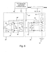
- Each partial discharge coupler may be substantially as set out in greater detail herein with regard to any one or more of Figs. 1-6 .
- each partial discharge coupler 26A, 26B, 26C, 26D, 26E, 26F and 26G is positioned between a corresponding conductor and an earth ground 32', 32".
- the output of each partial discharge coupler 26, which is coupled to the test equipment 40, is electrically isolated from the earth grounds 32', 32" and isophase buses 20, 22 and 24, as schematically represented by the separate ground 62.
- the above system allows time of flight and other tests to be conducted on partial discharge pulses using any desired processing techniques, e.g., to measure partial discharge pulses, to locate the origin of partial discharge pulses, etc.
- the differential amplifier 52 described more fully herein may be used as a buffer for driving the partial discharge information along the output 38 to the appropriate testing equipment 40.
- partial discharge pulses are typically small signal level, e.g., 100 millivolts in magnitude, high frequency pulses that attenuate rapidly as they travel from the partial discharge coupler towards the testing equipment. This may result in the loss of smaller amplitude partial discharge pulses when traveling from/through a conventional partial discharge coupler to corresponding partial discharge testing equipment.
- the partial discharge coupler 26 comprises a differential amplifier 52 that buffers the detected partial discharge pulses, and thus preserves the magnitude of the pulse, preventing partial discharge pulses from attenuating, regardless of the distance that the detected signal has to be transmitted to reach the corresponding testing equipment 40.
- the differential amplifier 52 can be utilized to detect partial discharges with a better signal to noise ratio and interference rejection because, for example, the ground of the output 58 of the differential amplifier 52 is isolated from the ground 32 of the partial discharge coupler 26, and the inputs 54, 56 of the differential amplifier 52 are not isolated from the frequency dependent network 30, thus common mode magnetic field interference induced into the signal path to the differential amplifier 52, e.g., by the signal carried by the conductor of the corresponding electrical device is rejected, etc. That is, the superposition of external interference, noise, etc., can be mitigated.
- the differential amplifier can be used to amplify, normalize, buffer, calibrate, compensate, level match and/or perform other gain, impedance or data processing techniques to manipulate the detected partial discharge information for preservation of an accurate depiction of partial discharge pulse information for analysis by corresponding testing equipment 40.
- Conventional partial discharge couplers and coupling systems are passive and are thus subject to signal losses, interference and noise.
- gain may be applied by the differential amplifier 52 according to various aspects of the present invention, to overcome the signal to noise ratio of the line necessary to communicate partial discharge information to the corresponding test equipment.
- partial discharge pulses that would eventually get buried in noise in conventional systems can be readily detected and measured according to various aspects of the present invention.
- a conventional partial discharge coupler may utilize a passive circuit including a high frequency current transformer placed around a grounded high voltage capacitor circuit. This coupler circuit is connected to the high voltage bus at one end and earth ground at the other. While this design is simple, it suffers from performance constraints and other concerns. This form of partial discharge coupler however, distorts the partial discharge pulse, making it difficult to determine accurately, the exact time that the pulse arrived at the coupler on the isophase conductor. However, accurate pulse timing may be required to ascertain the origin of each partial discharge pulse.
- the partial discharge coupler 26 includes active circuitry 36, such as a differential amplifier 52, which provides a high impedance input to the partial discharge pulses, thus minimizing attenuation of the pulse due to the partial discharge coupler itself. As such, deformation of the partial discharge pulse due to loading that typically occurs in conventional partial discharge couplers may be minimized.
- the active circuitry 36 can drive the lines associated with the output 38 so that the transmitted partial discharge information is preserved in a much more accurate manner.
- the first filter component 42, the fuse component 44, the coupling component 34, the overload protection 36 all provide redundancy to prevent the possibility of a high voltage propagating from the partial discharge coupler 26 through signal wires that carry the partial discharge pulse information to corresponding test equipment 40.
Abstract
a frequency dependent network (30) having a first filter component (42), a fuse component (44) and a load component (46), connected in series, wherein:
the first filter component is configured to pass high frequency partial discharge pulse signals to the load component;
the fuse component is configured to provide overload protection;
the load component defines a first node (48) and a second node (50), the second node being configured to couple to the first ground; and
a connector socket (70) having a first socket connection (72), a second socket connection (74) and a shorting connection (76), wherein:
the shorting connection is configured to electrically connect/disconnect the first socket connection to/from the second socket connection; and
a frequency selective coupling component (34).
Description
- This application claims the benefit of
U.S. Provisional Application Serial No. 61/099,648 - The present invention relates in general to partial discharge couplers, and in particular, to partial discharge couplers for use with high voltage generator bus works.
- High voltage electrical applications, such as high-voltage dynamoelectric machines, electrical generators in power plants, etc., represent capital intensive installations and typically require high availability in order to be operated in an economical manner. However, a breakdown of the insulation in such a high voltage electrical application can have significant consequences, including potential damage to the electrical device and/or components electrically coupled to the device. In this regard, proactive measures may be utilized to predict an impending breakdown. One such proactive strategy is to evaluate an indicator of the integrity of a high voltage electrical device by measuring partial discharges.
- Partial discharges are small electrical sparks that occur within the insulation of electrical devices, such as windings in motors and generators. Partial discharges may also occur within the insulation of other electrical devices that are subject to high voltages, such as transformers and cables. More particularly, a partial discharge represents a localized breakdown of the electrical insulation of a component under high voltage stress. For example, localized breakdowns may occur in small air pockets within the electrical insulation. These electrical breakdowns exhibit themselves as high frequency electric current pulses that flow through the air pockets. Partial discharge measurements can be used as a predictor of reliability of the insulation of an electrical conductor, and thus a need for maintenance of the electrical device.
- Accordingly, it is common to monitor power plant generators, either continuously or at regular intervals to identify the occurrence of partial discharges that could be indicative of impending component failure. In an exemplary partial discharge monitor in power plants, passive partial discharge couplers are provided on each isophase bus connecting a generator
to a corresponding step up transformer. Partial discharge pulses detected by the partial discharge couplers are carried to testing equipment along corresponding signal lines for measurement and subsequent analysis. - According to various aspects of the present invention, a partial discharge coupler is provided, for detecting partial discharges in a conductor carrying a high voltage alternating current signal. The partial discharge coupler includes a frequency dependent network, a differential amplifier and a frequency selective coupling component that couples the differential amplifier to the frequency dependent network.
- The frequency dependent network may include a first filter component, a fuse component and a load component. The first filter component is configured to filter the high voltage, low frequency, alternating current signal carried by the conductor from the load component and is further configured to pass high frequency partial discharge pulse signals to the load component when the partial discharge coupler is installed between the conductor and a ground.
- The fuse component is configured to provide overload protection to the partial discharge coupler if a signal through the fuse component exceeds a predetermined fuse condition. For example, where the partial discharge coupler is installed between a power bus and an earth ground, the fuse component may comprise a fast clearing fuse that employs sub-60 Hz cycle operation to provide disconnect of the partial discharge coupler from the power bus if the predetermined fuse condition is exceeded.
- The load component defines a first node and a second node. The first node is connected to the remainder of the network and the second node is coupled to ground when the frequency dependent network is installed between the conductor and the ground.
- The differential amplifier includes a first differential input, a second differential input and an output. The frequency selective coupling component is coupled in series between the first differential input of the differential amplifier and the first node of the load component, and is configured to pass high frequency partial discharge signals to the differential amplifier, and to filter low frequency alternating current signals from the differential amplifier. The second differential input of the differential amplifier is coupled to the second node of the load component, and the output of the differential amplifier is configured to provide an output that is isolated from the first ground connection for communicating detected partial discharge signals to partial discharge test equipment.
- According to further aspects of the present invention, a partial discharge coupler is provided for detecting partial discharges in a conductor carrying a high voltage alternating current signal. The partial discharge coupler includes a frequency dependent network having a first filter component, a fuse component and a load component, connected in series with each other. The first filter component is configured to filter the high voltage, low frequency alternating current signal carried by the conductor from the load component and to pass high frequency partial discharge pulse signals to the load component when the partial discharge coupler is installed between the conductor and a ground. The fuse component is configured to provide overload protection to the partial discharge coupler if a signal through the fuse component exceeds a predetermined fuse condition. The load component defines a first node and a second node. The first node is connected to the remainder of the series network and the second node is coupled to the ground when the frequency dependent network is installed between the conductor and the ground.
- The partial discharge coupler further includes a connector socket having a first socket connection, a second socket connection and a shorting connection. The shorting connection electrically couples (shunts) the first socket connection to the second socket connection when no corresponding plug is inserted into the socket connection. The shorting connection also electrically disconnects the first socket connection from the second socket connection when a corresponding plug is connected to the connector socket. A frequency selective coupling component is coupled in series between the first socket connection of the connector socket and the first node of the load component. Moreover, the second socket connection is coupled to the second node of the load component.
- The partial discharge coupler may further include a differential amplifier having a first differential input, a second differential input and an output. The output of the differential amplifier is typically communicated to partial discharge analysis equipment and is configured to provide an output that is isolated from the ground connection of the frequency dependent network. Still further, a plug is coupled to the differential amplifier that can be selectively plugged into and removed from connection with the connector socket, such that when the plug is connected to the connector socket, the first differential input of the differential amplifier is coupled to the frequency dependent coupling component via the first socket connection and the second differential input of the differential amplifier is coupled to the second node of the load component via the second socket connection.
- In this regard, the differential amplifier may be selectively attached to, and removed from the frequency dependent network via the plug and corresponding connector socket. Moreover, either the differential amplifier and/or shunt is electrically connected (in place) across the connector socket, depending upon whether or not the plug is mated with its corresponding connector socket. As such, the frequency selective coupling component is not left in an electrically open circuit state.
- According to still further aspects of the present invention, a partial discharge coupling system for coupling an electrical generator having at least one bus bar that carries a high voltage, low frequency alternating current signal to partial discharge testing equipment is provided. The system includes at least two partial discharge couplers associated with each bus bar that are spaced from each other by a predetermined distance. Each partial discharge coupler includes a frequency dependent network for installation between the associated bus bar and a ground, including a first filter component, a fuse component and a load component. The first filter component filters low frequency signals from the load component and passes high frequency partial discharge pulse signals to the load component. The load component defines a first node and a second node.
- Moreover, each partial discharge coupler includes a differential amplifier having a first differential input, a second differential input and an output that is provided with respect to a reference that is isolated from the ground coupled to the load component. A frequency selective coupling component is coupled in series between the first differential input of the differential amplifier and the first node of the load component. The second differential input of the differential amplifier is coupled to the second node of the load component.
- The following detailed description of various aspects of the present invention can be best understood when read in conjunction with the following drawings, where like structure is indicated with like reference numerals, and in which:
-
Fig. 1 is a diagrammatic view of a power plant system including partial discharge couplers according to various aspects of the present invention; -
Fig. 2 is a diagrammatic view of a partial discharge coupler according to various aspects of the present invention; -
Fig. 3 is a diagrammatic view of select components of a partial discharge coupler according to various aspects of the present invention; -
Fig. 4 is a diagrammatic view of selected components of a partial discharge coupler implemented with a pluggable configuration according to various aspects of the present invention; -
Fig. 5 is a diagrammatic view of selected components of a partial discharge coupler implemented with a pluggable configuration according to various aspects of the present invention; -
Fig. 6 is a diagrammatic view of the pluggable configuration ofFigs. 4 and5 according to various aspects of the present invention; and -
Fig. 7 is a diagrammatic view of a system for measuring partial discharge pulses using partial discharge couplers according to various aspects of the present invention. - In the following detailed description, reference is made to the accompanying drawings that form a part hereof, and in which is shown by way of illustration, and not by way of limitation, specifics from which various aspects of the present invention may be practiced. It is to be understood that other aspects may be utilized and that changes may be made without departing from the spirit and scope of the present invention.
- Referring now to the drawings, and in particular, to
Fig. 1 , apower plant system 10 includes in general, an electrical generator, e.g., aturbine generator 12 that is electrically coupled to a step-uptransformer 14 by a generator bus works 16. The step-uptransformer 16 is further coupled todownstream power lines 18 for delivering electrical power outside of thepower plant system 10. The generator bus works 16 typically includes one or more electrically insulated isophase buses. For example, the generator bus works 16 illustrated inFig. 1 is implemented as three isophase buses, including afirst isophase bus 20, asecond isophase bus 22 and athird isophase bus 24. - Each
isophase bus isophase bus generator 12 to the step-uptransformer 14. Moreover, the high voltage alternating current signal carried by each of theisophase buses - Each
isophase bus
large internal current carrying bus conductor that is suspended in air by porcelain supports. Moreover, the porcelain supports are mounted to the inner surface of a grounded cover/shield such as an outer cylindrical member. The large air gap between the center bus conductor and outer grounded cover provides electrical insulation. Partial discharge can occur within this bus work. However, partial discharges are more problematic in thegenerator 12 and step-uptransformer 14. In particular, partial discharges such as small sparks can occur in the insulation around the generator and step-up transformer winding e.g., via localized breakdowns in small air pockets within the electrical insulation. These partial discharges do not propagate completely from phase to phase or phase to ground. Therefore, measurement and analysis of these partial discharges can provide an early warning of insulation failures in high voltage electrical devices. - According to various aspects of the present invention, partial discharge couplers are provided, which are designated generally by the
reference numeral 26. Thepartial discharge couplers 26 are capable of detecting partial discharge pulse information in thegenerator 12, step-uptransformer 14 and/or generator bus works 16. The detected partial discharge pulse information is then conveyed to corresponding testing and analysis equipment (not shown inFig. 1 ). - For example,
Fig. 1 illustrates twopartial discharge couplers first isophase bus 20. Twopartial discharge couplers second isophase bus 22. Also, twopartial discharge couplers third isophase bus 24. Although illustrated as having two partial discharge couplers on each isophase, other arrangements may alternatively be implemented, depending for example, upon the particular application and/or partial discharge measuring requirements. Moreover, even though thepartial discharge couplers 26 are illustrated as being coupled to the generator bus works 16 inFig. 1 , suchpartial discharge couplers 26 may be utilized to capture partial discharge pulse information for any number of alternative high voltage electrical devices. - Referring to
Fig. 2 , apartial discharge coupler 26 is illustrated according to various aspects of the present invention. In general, thepartial discharge coupler 26 comprises a frequencydependent network 30 that may be connected between an electrical device, e.g., an isophase bus bar such as one of the isophase bus bars 20, 22, 24 discussed with reference toFig. 1 , and afirst ground reference 32, e.g., an earth ground. Acoupling component 34 couples the
frequencydependent network 30 to anamplifier circuit 36. Thepartial discharge coupler 26 also provides anoutput 38 from theamplifier circuit 36 that may be coupled totest equipment 40, e.g., a partial discharge analyzer or other suitable equipment for analyzing partial discharge pulses. In practice, the isophase bus outer cylindrical shield is typically earth grounded. As such, thepartial discharge coupler 26 may be installed within an extension, i.e., a modification, of the isophase bus outer cylindrical shield, which is configured to insure proper high voltage isolation of the inner bus conductor. - Referring to
Fig. 3 , apartial discharge coupler 26 is illustrated according to various aspects of the present invention. The illustratedpartial discharge coupler 26 includes a frequencydependent network 30 having afirst filter component 42, afuse component 44 and aload component 46. The frequencydependent network 30 filters the high voltage alternating current from the test equipment 40 (Fig. 2 ), and detects partial discharge pulses, which are communicated to thetest equipment 40 as will be described in greater detail herein. - The
first filter component 42 is configured to filter the high voltage, low frequency alternating current signal carried by the conductor of a connected electrical device from theload component 46 when thepartial discharge coupler 26 is installed between the conductor and a ground, e.g., anisophase bus earth ground 32. Correspondingly, thefirst filter component 42 is configured to pass detected high frequency partial discharge pulse signals to theload component 46, when thepartial discharge coupler 26 is installed between the conductor and the ground. Thefirst filter component 42 may be implemented, for example, using one or more capacitors that are configured to withstand the high voltage stress of an associated electrical device to which thepartial discharge coupler 26 is attached, e.g., an isophase bus bar, which may be carrying thousands of volts. The capacitor may comprise any suitable material, such as glass/ceramic material(s), polymer films, etc., and may be cylindrical, puck-shaped, etc. - Because of the filtering caused by the interaction of the capacitor and the load resistor, the capacitor implementing the
first filter component 42 is also referred to herein as an isolation capacitor. The isolation capacitor designates the interaction of the capacitor with theload component 46 to filter the high voltage alternating current signal carried by the conductor, .e.g., of the signal carried by theisophase bus load component 46 and to pass the high frequency partial discharge pulses to theload component 46 with minimal attenuation. - In an application for monitoring partial discharges in an isophase bus, a capacitor having the ability to withstand the stress of a voltage up to approximately 5 Kilovolts to approximately 30 Kilovolts may be required. In addition to being able to operate under constant high voltage stress conditions, the capacitor should also be capable of passing partial discharge pulses, which may comprise high frequency transient signals.
- As an illustrative example, the
first filter component 42, e.g., a first capacitor, is under constant high voltage stress by virtue of being coupled at one end to the high voltage alternating current signal carried by the conductor of theisophase bus Fig. 1 . This exposure to high voltage stress causes the capacitor to age. - In a conventional partial discharge coupler, should the capacitor fail and should a conductive path to ground be formed, the resulting component failure may trip the corresponding turbine generator and may cause costly damage to the isophase bus works 16 and/or other system components. A resulting high energy arc may also persist for many seconds as the generator core magnetic flux decays. Accordingly, a failure resulting in a conductive path to ground can cause substantial damage to the system. Many bus works are custom made. As such, extended power outages may result if the bus works is damaged due to the increased difficulty in implementing repairs to the customized features of the bus works.
- However, according to various aspects of the present invention, the frequency
dependent network 30 includes afuse component 44 that is provided to protect against potential damage due to component failure of thefirst filter component 42. Thefuse component 44 is configured to provide overload protection to the high voltage electrical application, thepartial discharge coupler 26 and/ordownstream test equipment 40 if a signal through thefuse component 44 exceeds a predetermined fuse condition, e.g., exceeds a predetermined current as may occur should the first filter component fail. For example, thefuse component 44 may isolate thepartial discharge coupler 26 from the conductor of the attached electrical device in the event of a failure of thefirst filter component 42, e.g., a capacitor failure, and thereby limit the capacitor fault or short circuit current that might otherwise form a conductive path to ground, from causing damage to system components. Thefuse component 44 should also be capable of passing high frequency transient signals with minimal attenuation. - In an exemplary implementation where the
partial discharge coupler 26 is coupled to an isophase bus works such as described with reference toFig. 1 , thefuse component 44 should be configured to provide separation of the components of thepartial discharge coupler 26
downstream of thefirst filter component 42 andfuse component 44 from the high voltage bus within a fraction of the 60 cycle line period, should thefirst filter component 42 fail. Moreover, thefuse component 44 should be capable of withstanding the bus voltage after the fuse has blown. - The
load component 46 defines afirst node 48 and asecond node 50. Thefirst node 48 is connected to the remainder of the network, e.g., thefuse component 44 as shown, and thesecond node 50 is coupled to theground 32 when thepartial discharge coupler 26 is installed between the conductor of the electrical device and the ground. Theload component 46 may be implemented for example, by a resistor, as will be described in greater detail herein. - The frequency
dependent network 30 is illustrated in the exemplarypartial discharge coupler 26 as a series network having the fuse component serially connected between thefirst filter component 42 and theload component 44. In practice, the components may be rearranged into other configurations. For example, thefirst filter component 42 may be relocated between thefuse component 44 and theload component 46, etc. Other arrangements of the components of the frequencydependent network 30 and/or alternative components may alternatively be implemented, so long as the partial discharge pulses of interest are filtered from the high voltage, alternating current signal carried by the conductor. For example, theload component 46 may alternatively be replaced with other structures such as an inductor or transformer, so long as the high frequency partial discharge pulse information can be filtered from the high voltage alternating current signal carried by the conductor of the attached electrical device. - The
partial discharge coupler 26 includes anamplifier circuit 36 that is coupled to the frequencydependent network 30 by acoupling component 34. Theamplifier circuit 36 may comprise, for example, adifferential amplifier 52 having a firstdifferential input 54, a seconddifferential input 56 and anoutput 58. The differential nature of theinputs differential amplifier 52 to reject common mode signals, noise, interference, etc., from the input of thedifferential amplifier 52 and hence the output thereof, such as from induced 60 Hz cycles of the high voltage signal carried by the conductor of the isophase bus. - The first
differential input 54 of thedifferential amplifier 52 is coupled to thefirst node 48 of theload component 46 via the series connectedcoupling component 34. The seconddifferential input 56 of thedifferential amplifier 52 is coupled to thesecond node 50 of theload component 46 and is thus coupled to theearth ground 32 when thepartial discharge coupler 26 is suitably installed for partial discharge detection. - The
differential amplifier 52 is configured to electrically isolate the partial discharge signal removed from the isophase bus, thus providing anoutput 58 that is isolated from thefirst ground connection 32, e.g., earth ground. For example, theoutput 58 of thedifferential amplifier 52 is taken relative to asecond ground 62, which is different from thefirst ground 32. Thus, theoutput 58 of thedifferential amplifier 52 is electrically isolated from the signals appearing acrossload component 46 of the frequencydependent network 30. This electricallyisolated output 58 may be evaluated to monitor the condition of thegenerator 12, step-uptransformer 14, bus works 16, etc. using partial discharge testing/analysis equipment 40. For example, as illustrated, theoutput 58 of thedifferential amplifier 52 couples to theoutput 38, e.g., wires that connect to testequipment 40. - Partial discharge pulses are typically small signal level, e.g., approximately 100 millivolts in magnitude, high frequency pulses that attenuate rapidly. However, other types of pulses carried by the conductor can reach relatively large voltages, e.g., hundreds to thousands of volts. For example, high voltage spikes may occur during normal unit trips when the voltage swing is within a specific region at the time of the unit trip. Depending upon where in the cycle the voltage is, e.g., relative to the zero crossing, inductance/kickback can produce a high voltage spike reaching hundreds of volts. Moreover, grid line faults (although infrequent) may also produce high frequency pulses that can reach thousands of volts in magnitude. As such, it is possible for high voltage spikes to appear across the
load component 46. - However, as illustrated, a
protection device 60 may be electrically coupled between the first and seconddifferential inputs differential amplifier 52 for providing overload protection, e.g., to protect thedifferential amplifier 52 and other downstream components from damage caused by unusually large voltage spikes that may appear across theload component 46. For example, theprotection device 60 may be designed to electrically conduct when a low set voltage is reached. This keeps otherwise high voltage pulses from theinputs differential amplifier 52. - The
protection device 60 may be implemented, for example, as a spark gap, surge suppressor, gas discharge, etc., which offers a high impedance to low voltage partial discharge pulse signals but becomes conductive should a threshold voltage level be exceeded. The surge suppressor thus limits the peak voltage that can appear across theinputs differential amplifier 52, thus protecting thedifferential amplifier 52 from fast and high pulses sometimes experienced in a normal unit trip. Thus, theprotection device 60 prevents spikes
from appearing across thedifferential amplifier inputs differential amplifier 52, i.e.,differential inputs output 58 of thedifferential amplifier 52. - In contrast, conventional partial discharge couplers allow these relatively large voltage pulses to pass through the partial discharge coupler and reach the partial discharge testing/analyzer circuits. For example, in a conventional partial discharge design, a coupling capacitor is connected to a conductor, e.g., carrying a
high voltage 60 Hz signal and a current transformer is placed on the low potential side of a coupling capacitor. Essentially, the low voltage end of the coupling capacitor is grounded and the current transformer is placed around this ground connection wire. - This conventional configuration may prevent the
high voltage 60 Hz signal from reaching a corresponding coupling transformer. However, high voltage spikes that may occur during normal unit trips, grid line faults and other conditions that can produce high magnitude voltage pulses are passed through the coupling transformer and can result in damage to expensive, high speed partial discharge monitor/analyzer circuits. Moreover, should the coupling capacitor fail, the current transformer is exposed to generator phase voltage which can then be carried to the partial discharge monitor/test equipment thus causing damage to the testing equipment. - However, according to various aspects of the present invention, the wiring of the
output 38 is inherently safe, as the high voltage pulse conditions described above are isolated from thedownstream equipment 40 by virtue of the electrically isolated differential output of thedifferential amplifier 52, and/or theprotection device 60. As such, the occurrence of a high voltage pulse across theload component 46 will not harmdownstream test equipment 40. - In an exemplary implementation, the
coupling component 34 is coupled in series between the firstdifferential input 54 of thedifferential amplifier 52 and thefirst node 48 of theload component 46. Thecoupling component 34 is configured to pass high frequency partial discharge signals detected across theload component 46 to thedifferential amplifier 52, and to filter low frequency alternating current signals from thedifferential amplifier 52. - The
coupling component 34 may be implemented for example, by a coupling capacitor. Because the coupling capacitor interacts with the input impedance of the differential amplifier, the coupling capacitor value may be chosen to provide frequency selectivity and is thus also referred to herein as a frequency selective coupling capacitor. For example, the coupling
capacitor value may be selected such that thecoupling component 34 serves as a redundant line of protection in case thefirst filter component 42 fails by filtering the high voltage, alternating current from thedifferential amplifier 52. Thecoupling capacitor 34 is only under high voltage stress should the load resistor open. - Referring to
Figs. 4 and5 , according to various aspects of the present invention, thepartial discharge coupler 26 may be implemented using two or more assemblies 26' (Fig. 4 ) and 26" (Fig. 5 ) that couple together using a coupling arrangement. With particular reference toFig. 4 , in an exemplary arrangement, a first partial discharge coupler assembly 26' may include the frequencydependent network 30 coupled to the first frequencyselective filter 34 set out and described more fully herein, e.g., with reference toFigs. 1-3 . - The first partial discharge coupler assembly 26' may further comprise a
connector socket 70. Theconnector socket 70 includes afirst socket connection 72, asecond socket connection 74 and ashorting connection 76. Thefirst socket connection 72 defines a first contact that is electrically connected to thecoupling component 34. Thesecond socket connection 74 defines a second contact that is electrically coupled to the load resistor/ground connection, e.g., atnode 50. The shortingconnection 76 electrically couples thefirst socket connection 72 to thesecond socket connection 74 when no corresponding jack is plugged into theconnector socket 70. Moreover, the shortingconnection 76 electrically disconnects thefirst socket connection 72 from thesecond socket connection 74 when a corresponding plug is connected to theconnector socket 70. Thecoupling component 34 is coupled serially between thefirst socket connection 72 and thefirst node 48 of theload component 46. - Referring to
Fig. 5 , a second partialdischarge coupler assembly 26" comprises aconnector plug 80 configured to mate with theconnector socket 70 ofFig. 4 . Theconnector plug 80 includes afirst plug connector 82 that is configured to mate with thefirst socket connection 72 of theconnector socket 70, and asecond plug connector 84 that is configured to mate with thesecond socket connection 74 of theconnector socket 70. Moreover, when theconnector plug 80 is suitably mated with theconnector socket 70, the shortingconnection 76 of theconnector socket 70 is opened so as to break the electrical short between thefirst socket connection 72 and thesecond socket connection 74. - The
first plug connector 82 couples to thefirst input 54 of thedifferential amplifier 52. Correspondingly, thesecond plug connector 84 couples to thesecond input 54 of thedifferential amplifier 52. Theprotection device 60 may also be electrically coupled between the first and seconddifferential inputs - In this regard, the
differential amplifier 52 may be selectively attached to, and removed from the frequencydependent network 30 via theplug 80 andcorresponding connector socket 70. When theplug 80 is disconnected from the correspondingconnector socket 70, the shortingconnection 76 of theconnector socket 70 shunts thefirst socket connection 72 to thesecond socket connection 74. When theplug 80 is inserted into theconnector socket 70, thedifferential amplifier 52 is connected between thefirst socket connection 72 and thesecond socket connection 74, and the shortingconnection 76 opens the short between the first nadsecond socket connections differential amplifier 52 and/or a shunt (via the shorting connection 76) is electrically connected (in place) across theconnector socket 70. As such, thefirst socket connection 72, and thus the frequencyselective coupling component 34, is not left in an electrically open circuit state (one end floating). - When the first partial discharge coupler assembly 26' is mated with the second partial
discharge coupler assembly 26", thepartial discharge coupler 26', 26" is electrically the same as thepartial discharge coupler 26 described with reference toFigs. 1-3 . However, under the arrangement ofFigs. 4 and5 , the second partialdischarge coupler assembly 26" may be disconnected/unplugged from the first partial discharge coupler assembly 26', e.g., for storage, repair, servicing, repositioning/re-use, etc. When the second partialdischarge coupler assembly 26" is unplugged from the first partial discharge coupler assembly 26', the shortingconnection 76 of theconnector socket 70 shorts thecoupling component 34 to ground, and allows theamplifier circuitry 36 to be safely removed from the first partial discharge coupler assembly 26'. - In this regard, the first partial discharge coupler assembly 26' may be fixedly installed in the environment, e.g., between an
isophase bus ground connection 32. The second partialdischarge coupler assembly 26" may be selectively plugged into the first partial discharge coupler assembly 26', e.g., during partial discharge pulse testing, and the second partialdischarge coupler assembly 26" may be detached from the first partial discharge coupler assembly 26', e.g., when not performing partial discharge pulse testing. - A differential
amplifier power supply 86 is also illustrated inFig. 5 . The differentialamplifier power supply 86 may be a single ended supply, or a bi-polar supply, depending upon the specific electronics implemented, and in particular, to the type of differential amplifier utilized. In that regard, other circuitry related to biasing, conditioning, filtering, etc., may be required, depending upon the amplifier and power supply implementation. Moreover, thepower supply 86 may attach to and couple power to the second partialdischarge coupler assembly 26" in any appropriate manner. For example, thepower supply 86 may attach with and/or otherwise be part of the second partialdischarge coupler assembly 26". Alternatively, thepower supply 86 may plug into the second partialdischarge coupler assembly 26" or otherwise provide power to theamplifier circuitry 36 when the second partialdischarge coupler assembly 26" is plugged into or otherwise docked with the first partial discharge coupler assembly 26'. - Referring to
Fig. 6 , the second partialdischarge coupler assembly 26" is illustrated as being inserted into the first partial discharge coupler assembly 26' to illustrate an exemplary manner in which theamplifier circuitry 36 may receive power. For example, a corresponding connecting arrangement may be required to couple thepower supply 86 to the amplifier, depending upon the specific implementation. While theconnector socket 70 is illustrated as having two inputs inFig. 4 , that is merely for purpose of clarity of discussion of coupling the partial discharge information from the load resistor to the amplifier. In practice, other more complicated plug arrangements may be utilized, e.g., which also couple power to theamplifier circuitry 36, e.g., usingcoupling arrangement 88' and 88". Under this arrangement, thepower supply 86 may be considered part of, integrated with, or otherwise coupled to the first partial discharge coupler assembly 26' shown inFig. 4 . As yet another illustrative example, the DC power required by thedifferential amplifier 52 may be provided as separate wiring that is bundled with theoutput 38 that connects thepartial discharge coupler 26 to thetest equipment 40. - As an illustrative example of the
partial discharge coupler 26 according to various aspects of the present invention, e.g., as shown in any of the Figures herein, assume that thepartial discharge coupler 26 is connected between a conductor of a power bus, e.g., anisophase bus earth ground 32. The isophase bus conductor may carry a high voltage, low frequency alternating current signal, such as a 60 Hertz power signal up to, or in excess of 20-30 Kilovolts in magnitude. - Further, assume that the
fuse component 44 comprises a fast clearing fuse (sub 60 Hz cycle operation) to provide disconnect of the partial discharge coupler from the power bus if the predetermined fuse condition is exceeded. As an illustrative example, thefuse component 44 may comprise a 0.5 ampere, 0.008 seconds high voltage fast clearing fuse capable of passing high frequency transient signals such as partial discharge pulses with minimal attenuation. The fast clearing fuse removes thepartial discharge coupler 26 from theisophase bus first filter component 42, e.g., an isolation capacitor fail. This serves to protect the downstream electronics, e.g., the partial discharge
analysis equipment and other components of the system from potentially damaging voltage conditions. - Further, assume that the
first filter component 42 comprises a high voltage isolation capacitor capable of withstanding the stress of the corresponding high voltage conductor, and that theload component 46 comprises a load resistor. The isolation capacitor may have a value in the range of approximately 100 picofarads. Correspondingly, the load resistor may have a value in the range of approximately 100 Ohms to 1,000 Ohms. Under this arrangement, the isolation capacitor appears like a high impedance to thehigh voltage 60 Hz power signal carried by the conductor of the isophase bus. However, the isolation capacitor appears as a low impedance to a high frequency partial discharge pulse. For example, the corner frequency of the high pass filter formed by the isolation capacitor and the load resistor may be in the range of approximately 1.59M Hz to 15.9M Hz for the above exemplary component values. In general, since this is a high pass filter, frequencies above the corner frequency are passed. However, in practice, the highest pass frequency is determined by the intrinsic small inductive nature of the circuit. As such, the exemplary circuit values may effectively pass signals in the range of 1.59M Hz to 200M Hz as an illustrative example. - The particular implemented values for the isolation capacitor and load resistor may vary, depending upon factors such as the frequency range of the partial discharge pulses of interest. For example, in some implementations, the isolation capacitor may be required to pass partial discharge signals having a pulse frequency in the megahertz range and other applications may require the isolation capacitor to pass partial discharge signals having a pulse frequency in the hundreds of megahertz range. For example, it may be desirable to extend the corner frequency up to 200 MHz or greater. Still further, yet other exemplary applications may require the isolation capacitor to pass partial discharge pulse signals having a pulse frequency in the gigahertz range.
- Returning to the present example, high frequency transient signals, e.g., partial discharge pulses, from the insulation surrounding the corresponding conductor of
generator 12, step-uptransformer 14 and/or generator bus works 16 are passed through the high voltage capacitor/first filter component 42 and are presented across the load resistor/load component 46. Thus, the high voltage isolation capacitor appears as a high impedance load to the high voltage, 60 Hz bus power voltage carried by theisophase buses
a low impedance to partial discharge pulses, the partial discharge pulse voltages of interest appear almost entirely across the load resistor, while substantially none of the 60 Hz bus voltage appears across resistor. - The partial discharge pulse signals are removed from across load resistor through the
coupling component 34 and are input to thedifferential amplifier 52. Thecoupling capacitor 34 may further be configured, e.g., via selection of an appropriate capacitance value, e.g., in view of the input impedance of thedifferential amplifier 52, to prevent the flow of high voltage alternating current, e.g.,high voltage 60 Hz signal current carried by the conductor of theisophase bus differential amplifier 52 should the isolation capacitor of thefirst filter component 42 fail. Theoutput 58 of thedifferential amplifier 52 is conveyed to appropriate testing andanalysis equipment 40. - Referring to
Fig. 7 , yet another exemplary partial discharge monitoring system is provided. In the exemplary application ofFig. 7 , according to various aspects of the present invention, a plurality ofpartial discharge couplers 26 are utilized to facilitate monitoring of partial discharge pulses in a generator system by detecting partial discharges along the threeisophase bus partial discharge coupler 26A is electrically connected between afirst isophase bus 20 and a first earth ground 32'. A secondpartial discharge coupler 26B is electrically connected between thefirst isophase bus 20 and asecond earth ground 32", spaced from the firstpartial discharge coupler 26A by a predetermined distance, e.g., 30-40 feet. A thirdpartial discharge coupler 26C is electrically connected between asecond isophase bus 22 and the first earth ground 32'. A fourthpartial discharge coupler 26D is electrically connected between thesecond isophase bus 22 and thesecond earth ground 32", spaced from the thirdpartial discharge coupler 26C by a predetermined distance, e.g., 30-40 feet. Similarly, a fifthpartial discharge coupler 26E is electrically connected between athird isophase bus 24 and the first earth ground 32'. A sixthpartial discharge coupler 26F is electrically connected between thethird isophase bus 24 and thesecond earth ground 32", spaced from the fifthpartial discharge coupler 26 E by a predetermined distance, e.g., 30-40 feet. A seventhpartial discharge coupler 26G may be utilized to monitor the difference in ground potential between the first earth ground 32' and thesecond earth ground 32". - Each partial discharge coupler may be substantially as set out in greater detail herein with regard to any one or more of
Figs. 1-6 . For example, although eachpartial discharge coupler earth ground 32', 32". The output of eachpartial discharge coupler 26, which is coupled to
thetest equipment 40, is electrically isolated from theearth grounds 32', 32" andisophase buses separate ground 62. The above system allows time of flight and other tests to be conducted on partial discharge pulses using any desired processing techniques, e.g., to measure partial discharge pulses, to locate the origin of partial discharge pulses, etc. - According to various aspects of the present invention, the
differential amplifier 52 described more fully herein, may be used as a buffer for driving the partial discharge information along theoutput 38 to theappropriate testing equipment 40. This avoids the losses encountered in conventional partial discharge couplers. For example, as noted in greater detail herein, partial discharge pulses are typically small signal level, e.g., 100 millivolts in magnitude, high frequency pulses that attenuate rapidly as they travel from the partial discharge coupler towards the testing equipment. This may result in the loss of smaller amplitude partial discharge pulses when traveling from/through a conventional partial discharge coupler to corresponding partial discharge testing equipment. However, according to various aspects of the present invention, thepartial discharge coupler 26 comprises adifferential amplifier 52 that buffers the detected partial discharge pulses, and thus preserves the magnitude of the pulse, preventing partial discharge pulses from attenuating, regardless of the distance that the detected signal has to be transmitted to reach thecorresponding testing equipment 40. - Moreover, the
differential amplifier 52 can be utilized to detect partial discharges with a better signal to noise ratio and interference rejection because, for example, the ground of theoutput 58 of thedifferential amplifier 52 is isolated from theground 32 of thepartial discharge coupler 26, and theinputs differential amplifier 52 are not isolated from the frequencydependent network 30, thus common mode magnetic field interference induced into the signal path to thedifferential amplifier 52, e.g., by the signal carried by the conductor of the corresponding electrical device is rejected, etc. That is, the superposition of external interference, noise, etc., can be mitigated. - Still further, the differential amplifier can be used to amplify, normalize, buffer, calibrate, compensate, level match and/or perform other gain, impedance or data processing techniques to manipulate the detected partial discharge information for preservation of an accurate depiction of partial discharge pulse information for analysis by corresponding
testing equipment 40. Conventional partial discharge couplers and coupling systems are passive and are thus subject to signal losses, interference and noise. However, for example, gain may be applied by thedifferential amplifier 52 according to various aspects of the present invention, to overcome the signal to noise ratio of the line necessary to communicate partial discharge information to the corresponding test equipment. Thus, partial discharge pulses that would eventually get buried in noise in conventional systems can be readily detected and measured according to various aspects of the present invention. - Additionally, a conventional partial discharge coupler may utilize a passive circuit including a high frequency current transformer placed around a grounded high voltage capacitor circuit. This coupler circuit is connected to the high voltage bus at one end and earth ground at the other. While this design is simple, it suffers from performance constraints and other concerns. This form of partial discharge coupler however, distorts the partial discharge pulse, making it difficult to determine accurately, the exact time that the pulse arrived at the coupler on the isophase conductor. However, accurate pulse timing may be required to ascertain the origin of each partial discharge pulse.
- However, the
partial discharge coupler 26 according to various aspects of the present invention includesactive circuitry 36, such as adifferential amplifier 52, which provides a high impedance input to the partial discharge pulses, thus minimizing attenuation of the pulse due to the partial discharge coupler itself. As such, deformation of the partial discharge pulse due to loading that typically occurs in conventional partial discharge couplers may be minimized. Moreover, theactive circuitry 36 can drive the lines associated with theoutput 38 so that the transmitted partial discharge information is preserved in a much more accurate manner. - Moreover, according to various aspects of the present invention, the
first filter component 42, thefuse component 44, thecoupling component 34, theoverload protection 36, all provide redundancy to prevent the possibility of a high voltage propagating from thepartial discharge coupler 26 through signal wires that carry the partial discharge pulse information to correspondingtest equipment 40. - Having thus described the invention of the present application in detail and by reference to embodiments thereof, it will be apparent that modifications and variations are possible without departing from the scope of the invention defined in the appended claims.
Claims (7)
- A partial discharge coupler (26', 26") for installation between a conductor (20, 22, 24) carrying a high voltage alternating current signal and a first ground (32) for detecting partial discharges in the conductor, the partial discharge coupler comprising:a frequency dependent network (30) having a first filter component (42), a fuse component (44) and a load component (46), connected in series, wherein:the first filter component is configured to filter the high voltage, low frequency alternating current signal carried by the conductor from the load component and to pass high frequency partial discharge pulse signals to the load component;the fuse component is configured to provide overload protection to the partial discharge coupler if a signal through the fuse component exceeds a predetermined fuse condition;the load component defines a first node (48) and a second node (50), the second node being configured to couple to the first ground; anda connector socket (70) having a first socket connection (72), a second socket connection (74) and a shorting connection (76), wherein:the shorting connection is configured to electrically connect the first socket connection to the second socket connection in the absence of a corresponding connector plug (80) connected to the connector socket,the shorting connection is configured to electrically disconnect the first socket connection from the second socket connection in the presence of the corresponding connector plug connected to the connector socket, andthe second socket connection is coupled to the second node of the load component; anda frequency selective coupling component (34) that is coupled in series between the first socket connection and the first node of the load component.
- The partial discharge coupler according to claim 1, further comprising:a differential amplifier (52) having a first differential input (54), a second differential input (56) and an output (58), the output of the differential amplifier configured to provide an output that is isolated from the first ground for communicating detected partial discharge signals to partial discharge test equipment (40);a connector plug (80) coupled to the differential amplifier for connection to the connector socket, such that:the first differential input of the differential amplifier is coupled to the frequency selective coupling component via the first socket connection; andthe second differential input of the differential amplifier is coupled to the second node of the load component via the second socket connection.
- The partial discharge coupler according to claim 2, further comprising a surge suppression component (60) coupled between the first and second differential inputs of the differential amplifier, the surge suppression component configured to protect the differential amplifier if the differential voltage seen by the differential inputs exceeds at least one predetermined condition.
- The partial discharge coupler according to claim 2, wherein the differential amplifier is configured to reject common mode magnetic field interference induced into the signal path to the differential amplifier by the signal carried by the conductor.
- The partial discharge coupler according to claim 1, wherein:the first filter component comprises a capacitor configured to withstand a high voltage stress;the fuse component comprises a fuse in series with the capacitor; andthe load component comprises a resistor in series with the capacitor and the fuse.
- The partial discharge coupler according to claim 3, wherein the capacitance of the first filter component and the resistance of the load component are selected so as to filter the low frequency alternating current signal from the load component and to pass high frequency partial discharge pulses to the load component.
- The partial discharge coupler according to claim 1, wherein the frequency selective coupling component comprises a capacitor.
Applications Claiming Priority (3)
| Application Number | Priority Date | Filing Date | Title |
|---|---|---|---|
| US9964808P | 2008-09-24 | 2008-09-24 | |
| US12/360,923 US8098072B2 (en) | 2008-09-24 | 2009-01-28 | Partial discharge coupler for application on high voltage generator bus works |
| EP09760360A EP2344898B1 (en) | 2008-09-24 | 2009-08-25 | Partial discharge coupler for application on high voltage generator bus works |
Related Parent Applications (1)
| Application Number | Title | Priority Date | Filing Date |
|---|---|---|---|
| EP09760360.9 Division | 2009-08-25 |
Publications (2)
| Publication Number | Publication Date |
|---|---|
| EP2453247A1 true EP2453247A1 (en) | 2012-05-16 |
| EP2453247B1 EP2453247B1 (en) | 2013-06-19 |
Family
ID=42036974
Family Applications (2)
| Application Number | Title | Priority Date | Filing Date |
|---|---|---|---|
| EP12152310.4A Not-in-force EP2453247B1 (en) | 2008-09-24 | 2009-08-25 | Partial discharge coupler for application on high voltage generator bus works |
| EP09760360A Not-in-force EP2344898B1 (en) | 2008-09-24 | 2009-08-25 | Partial discharge coupler for application on high voltage generator bus works |
Family Applications After (1)
| Application Number | Title | Priority Date | Filing Date |
|---|---|---|---|
| EP09760360A Not-in-force EP2344898B1 (en) | 2008-09-24 | 2009-08-25 | Partial discharge coupler for application on high voltage generator bus works |
Country Status (3)
| Country | Link |
|---|---|
| US (1) | US8098072B2 (en) |
| EP (2) | EP2453247B1 (en) |
| WO (1) | WO2010036469A2 (en) |
Cited By (1)
| Publication number | Priority date | Publication date | Assignee | Title |
|---|---|---|---|---|
| RU2815081C1 (en) * | 2023-08-29 | 2024-03-11 | федеральное государственное бюджетное образовательное учреждение высшего образования "Самарский государственный технический университет" | Arc and partial discharge protection device |
Families Citing this family (27)
| Publication number | Priority date | Publication date | Assignee | Title |
|---|---|---|---|---|
| AT506815B1 (en) * | 2008-05-28 | 2009-12-15 | Mohaupt Peter Dipl Ing | VLF test |
| IT1394479B1 (en) * | 2009-05-29 | 2012-07-05 | Techimp Technologies S A Ora Techimp Technologies S R L | INSTRUMENT AND PROCEDURE FOR DETECTION OF PARTIAL ELECTRIC DISCHARGES IN AN ELECTRIC EQUIPMENT. |
| IT1398250B1 (en) * | 2010-03-10 | 2013-02-22 | Techimp Technologies S A Ora Techimp Technologies S R L | INSTRUMENT AND PROCEDURE TO DETECT PARTIAL ELECTRIC DISCHARGE |
| RU2565349C2 (en) * | 2010-11-04 | 2015-10-20 | Альстом Текнолоджи Лтд | Sensor of partial discharges for online testing device of hv insulation |
| EP2466324B1 (en) | 2010-12-15 | 2013-07-24 | ABB Technology AG | Combined measuring and detection system |
| ES2711826T3 (en) * | 2010-12-30 | 2019-05-07 | Prysmian Spa | Location of faults generating partial discharges |
| JP5663318B2 (en) * | 2011-01-19 | 2015-02-04 | 株式会社日立製作所 | Partial discharge test method for inverter-driven rotating electrical machines |
| US8525523B2 (en) | 2011-05-03 | 2013-09-03 | General Electric Company | Partial discharge analysis coupling device that generates a pulse signal and a reference signal |
| DE102011080115A1 (en) * | 2011-07-29 | 2013-01-31 | Siemens Aktiengesellschaft | Decoupling unit for partial discharge measurement of high-voltage machines, has insulating support, which is connected to plastic overmoulding block through screw connection, where connector plug is fastened to cable |
| US8625242B2 (en) * | 2011-08-03 | 2014-01-07 | Maxim Integrated Products, Inc. | Failsafe galvanic isolation barrier |
| FR2981457B1 (en) | 2011-10-12 | 2015-04-03 | Michel Gaeta | METHOD AND DEVICE FOR DETECTING DYSFUNCTION IN AN ELECTRICAL NETWORK |
| CN102914729B (en) * | 2012-10-16 | 2015-08-05 | 西安交通大学 | A kind of mine cable partial discharge monitoring and position pulse emitter |
| CN103197209B (en) * | 2013-03-27 | 2015-04-08 | 西安电子科技大学 | Partial discharge work frequency synchronization signal sensing device |
| CN105358996A (en) * | 2013-07-02 | 2016-02-24 | 皇家飞利浦有限公司 | Problem monitoring in cable system with fuses |
| CN103675619A (en) * | 2013-11-30 | 2014-03-26 | 成都科泰地理信息技术有限公司 | Switch cabinet local discharge detecting instrument based on ultrahigh frequency antenna sensor |
| CN103616624B (en) * | 2013-12-13 | 2016-06-01 | 国家电网公司 | A kind of partial discharge monitoring system |
| CN104267326A (en) * | 2014-10-23 | 2015-01-07 | 广州供电局有限公司 | Partial discharge signal detection system |
| CN104698351B (en) * | 2015-02-12 | 2019-12-10 | 国家电网公司 | switch cabinet partial discharge monitoring device |
| CN107810422B (en) * | 2015-06-05 | 2021-05-04 | 奥马萨瓦尔防护与自动化有限公司 | System for detecting and indicating partial discharges and voltages |
| JP6414520B2 (en) * | 2015-07-14 | 2018-10-31 | 株式会社デンソー | Inspection system |
| CN105548846A (en) * | 2016-02-01 | 2016-05-04 | 广州智丰电气科技有限公司 | Signal frequency conversion preposition module of portable intelligent four-channel partial discharge detector |
| CA3007729A1 (en) | 2017-06-12 | 2018-12-12 | Vibrosystm Inc. | Method of monitoring partial discharges in a high voltage electric machine, and connection cable therefore |
| CN107248343A (en) * | 2017-06-15 | 2017-10-13 | 杭州易休特科技有限公司 | A kind of distribution net equipment partial discharge failure actual training device |
| DE102017216644A1 (en) * | 2017-09-20 | 2019-03-21 | Siemens Aktiengesellschaft | Method and arrangement for detecting partial discharges in an electrical equipment |
| CN109001580B (en) * | 2018-09-26 | 2021-09-10 | 西安理工大学 | Intelligent electric quantity transmission device of generator |
| CN111521917A (en) * | 2020-05-09 | 2020-08-11 | 中国电建集团华东勘测设计研究院有限公司 | Anti-interference measurement system for partial discharge of generator |
| CN113567741A (en) * | 2021-07-19 | 2021-10-29 | 国网陕西省电力公司电力科学研究院 | Method and system for monitoring state of oil-less equipment of transformer substation on line |
Citations (8)
| Publication number | Priority date | Publication date | Assignee | Title |
|---|---|---|---|---|
| US4224486A (en) * | 1979-03-05 | 1980-09-23 | Amp Incorporated | Shunt protected power connector |
| EP0488719A2 (en) * | 1990-11-30 | 1992-06-03 | Kabushiki Kaisha Toshiba | System and method for detecting partial discharge of gas-insulated switchgear |
| US5834940A (en) * | 1996-09-24 | 1998-11-10 | Brooks; Stanley J. | Arcing fault detector testing and demonstration system |
| US6285538B1 (en) * | 1996-02-20 | 2001-09-04 | General Electric Company | Partial discharge coupler |
| EP1367678A2 (en) * | 2002-05-23 | 2003-12-03 | Positronic Industries, Inc. | Electrical connector assembly with shorting member |
| EP1645887A2 (en) * | 2004-10-08 | 2006-04-12 | Ansaldo Energia S.P.A. | Instrument for detecting and analysing partial discharges in electrical machines |
| GB2429790A (en) * | 2005-09-05 | 2007-03-07 | Univ Glasgow | High voltage insulation monitoring sensor |
| US7354287B1 (en) * | 2006-10-31 | 2008-04-08 | Caterpillar Inc. | Shorting connector |
Family Cites Families (13)
| Publication number | Priority date | Publication date | Assignee | Title |
|---|---|---|---|---|
| JPS6016163B2 (en) * | 1978-02-03 | 1985-04-24 | 株式会社日立製作所 | Gas insulated electrical equipment and its partial discharge detection method |
| DE3526149A1 (en) * | 1985-06-15 | 1986-12-18 | Kraftwerk Union AG, 4330 Mülheim | CONNECTING UNIT FOR THE OPERATIONAL MONITORING OF THE HIGH VOLTAGE WINDINGS AND THE CONNECTED LEADS FOR ELECTRICAL HIGH VOLTAGE MACHINES AND APPARATUS, BY MEANS OF PARTIAL DISCHARGE DETECTION AND TAKE-OFF SPARK MEASUREMENT |
| DE3543927A1 (en) * | 1985-12-12 | 1987-06-19 | Kraftwerk Union Ag | METHOD FOR PARTIAL DISCHARGE DETECTION AND Tear-off Spark Measurement in DYNAMOELECTRIC HIGH-VOLTAGE MACHINES AND DEVICE FOR ITS IMPLEMENTATION |
| DE3764009D1 (en) * | 1986-04-14 | 1990-09-06 | Siemens Ag | METHOD AND DEVICES FOR DETECTING AND LOCALIZING DAMAGE IN ELECTRICAL SYSTEMS. |
| CA2008898C (en) * | 1989-10-25 | 1998-11-24 | Takeshi Endoh | Method for detecting partial discharge in an insulation of an electric power apparatus |
| GB9005243D0 (en) * | 1990-03-08 | 1990-05-02 | Bicc Plc | An improved isolated phase busbar installation |
| JP3187642B2 (en) * | 1994-02-25 | 2001-07-11 | 関西電力株式会社 | Electrical device abnormality detection method and rotating electrical machine abnormality detection device |
| SE515388C2 (en) * | 1995-09-14 | 2001-07-23 | Abb Research Ltd | Device for sensing electrical discharges in a sample object |
| DE29518286U1 (en) * | 1995-11-17 | 1996-01-18 | Siemens Ag | Device for locating partial discharges in dynamoelectric high-voltage machines and / or high-voltage systems |
| US5991137A (en) * | 1996-02-20 | 1999-11-23 | General Electric Company | Partial discharge coupler |
| WO2004034070A1 (en) * | 2002-10-10 | 2004-04-22 | Hanyang Hak Won Co., Ltd. | Hybrid type sensor for detecting high frequency partial discharge |
| FR2845772B1 (en) * | 2002-10-11 | 2005-01-21 | Airbus France | METHOD OF DETECTING FAULT OF SHIELDING A MULTIFILAR CABLE |
| EP1623240B1 (en) * | 2003-05-09 | 2008-04-09 | Siemens Aktiengesellschaft | Measuring device, and method for locating a partial discharge |
-
2009
- 2009-01-28 US US12/360,923 patent/US8098072B2/en not_active Expired - Fee Related
- 2009-08-25 EP EP12152310.4A patent/EP2453247B1/en not_active Not-in-force
- 2009-08-25 EP EP09760360A patent/EP2344898B1/en not_active Not-in-force
- 2009-08-25 WO PCT/US2009/054883 patent/WO2010036469A2/en active Application Filing
Patent Citations (8)
| Publication number | Priority date | Publication date | Assignee | Title |
|---|---|---|---|---|
| US4224486A (en) * | 1979-03-05 | 1980-09-23 | Amp Incorporated | Shunt protected power connector |
| EP0488719A2 (en) * | 1990-11-30 | 1992-06-03 | Kabushiki Kaisha Toshiba | System and method for detecting partial discharge of gas-insulated switchgear |
| US6285538B1 (en) * | 1996-02-20 | 2001-09-04 | General Electric Company | Partial discharge coupler |
| US5834940A (en) * | 1996-09-24 | 1998-11-10 | Brooks; Stanley J. | Arcing fault detector testing and demonstration system |
| EP1367678A2 (en) * | 2002-05-23 | 2003-12-03 | Positronic Industries, Inc. | Electrical connector assembly with shorting member |
| EP1645887A2 (en) * | 2004-10-08 | 2006-04-12 | Ansaldo Energia S.P.A. | Instrument for detecting and analysing partial discharges in electrical machines |
| GB2429790A (en) * | 2005-09-05 | 2007-03-07 | Univ Glasgow | High voltage insulation monitoring sensor |
| US7354287B1 (en) * | 2006-10-31 | 2008-04-08 | Caterpillar Inc. | Shorting connector |
Cited By (1)
| Publication number | Priority date | Publication date | Assignee | Title |
|---|---|---|---|---|
| RU2815081C1 (en) * | 2023-08-29 | 2024-03-11 | федеральное государственное бюджетное образовательное учреждение высшего образования "Самарский государственный технический университет" | Arc and partial discharge protection device |
Also Published As
| Publication number | Publication date |
|---|---|
| US20100073008A1 (en) | 2010-03-25 |
| US8098072B2 (en) | 2012-01-17 |
| EP2344898B1 (en) | 2012-10-31 |
| EP2453247B1 (en) | 2013-06-19 |
| WO2010036469A2 (en) | 2010-04-01 |
| WO2010036469A3 (en) | 2010-08-19 |
| EP2344898A2 (en) | 2011-07-20 |
Similar Documents
| Publication | Publication Date | Title |
|---|---|---|
| EP2344898B1 (en) | Partial discharge coupler for application on high voltage generator bus works | |
| Stone | Partial discharge. VII. Practical techniques for measuring PD in operating equipment | |
| US10522998B2 (en) | Method for detecting an open-phase condition of a transformer | |
| US8537510B2 (en) | Method and apparatus for monitoring the isolation of an IT-Grid | |
| Sedding et al. | A new sensor for detecting partial discharges in operating turbine generators | |
| KR101070832B1 (en) | A method for detecting an abnormality of distributing board | |
| Stone et al. | Objective methods to interpret partial-discharge data on rotating-machine stator windings | |
| JPS62250378A (en) | Method and device for recognizing trouble of electric facility and making sure position thereof | |
| CN103080757A (en) | Device and method for detecting a ground fault | |
| Stone et al. | In-service evaluation of motor and generator stator windings using partial discharge tests | |
| JP4871511B2 (en) | Interrupt insulation measuring device | |
| EP2482090A1 (en) | System for measuring partial discharges in power lines | |
| Weissenberg et al. | On-site PD detection at cross-bonding links of HV cables | |
| Kurtz et al. | In-service partial discharge testing of generator insulation | |
| JPH03128471A (en) | Monitoring device for insulation deterioration of electric equipment | |
| JP5204558B2 (en) | Discharge measuring device for impulse test and discharge discrimination method | |
| Suwanasri et al. | Partial discharge detection in high voltage equipment using high frequency current transducer | |
| Naseri et al. | Incipient fault monitoring of medium voltage UD-EPR power cable using Rogowski coil | |
| Sano et al. | Experimental investigation on FRA diagnosis of transformer faults | |
| Amorim et al. | Experience with on-line insulation diagnostics of surge arresters by PD measurement in the field | |
| Berler et al. | Partial discharge on-line monitoring in switchgears and bus ducts | |
| Su et al. | New techniques for on-line partial discharge measurements | |
| Berler et al. | Practical experience in on-line partial discharge measurements of MV switchgear systems | |
| Kurtz et al. | Fault anticipator for substation equipment | |
| Timperley et al. | Electromagnetic interference data collection from bus coupler capacitors |
Legal Events
| Date | Code | Title | Description |
|---|---|---|---|
| PUAI | Public reference made under article 153(3) epc to a published international application that has entered the european phase |
Free format text: ORIGINAL CODE: 0009012 |
|
| AC | Divisional application: reference to earlier application |
Ref document number: 2344898 Country of ref document: EP Kind code of ref document: P |
|
| AK | Designated contracting states |
Kind code of ref document: A1 Designated state(s): AT BE BG CH CY CZ DE DK EE ES FI FR GB GR HR HU IE IS IT LI LT LU LV MC MK MT NL NO PL PT RO SE SI SK SM TR |
|
| 17P | Request for examination filed |
Effective date: 20121109 |
|
| GRAP | Despatch of communication of intention to grant a patent |
Free format text: ORIGINAL CODE: EPIDOSNIGR1 |
|
| GRAS | Grant fee paid |
Free format text: ORIGINAL CODE: EPIDOSNIGR3 |
|
| GRAA | (expected) grant |
Free format text: ORIGINAL CODE: 0009210 |
|
| AC | Divisional application: reference to earlier application |
Ref document number: 2344898 Country of ref document: EP Kind code of ref document: P |
|
| AK | Designated contracting states |
Kind code of ref document: B1 Designated state(s): AT BE BG CH CY CZ DE DK EE ES FI FR GB GR HR HU IE IS IT LI LT LU LV MC MK MT NL NO PL PT RO SE SI SK SM TR |
|
| REG | Reference to a national code |
Ref country code: GB Ref legal event code: FG4D |
|
| REG | Reference to a national code |
Ref country code: CH Ref legal event code: EP |
|
| REG | Reference to a national code |
Ref country code: AT Ref legal event code: REF Ref document number: 617936 Country of ref document: AT Kind code of ref document: T Effective date: 20130715 |
|
| REG | Reference to a national code |
Ref country code: IE Ref legal event code: FG4D |
|
| REG | Reference to a national code |
Ref country code: DE Ref legal event code: R096 Ref document number: 602009016636 Country of ref document: DE Effective date: 20130814 |
|
| PG25 | Lapsed in a contracting state [announced via postgrant information from national office to epo] |
Ref country code: ES Free format text: LAPSE BECAUSE OF FAILURE TO SUBMIT A TRANSLATION OF THE DESCRIPTION OR TO PAY THE FEE WITHIN THE PRESCRIBED TIME-LIMIT Effective date: 20130930 Ref country code: LT Free format text: LAPSE BECAUSE OF FAILURE TO SUBMIT A TRANSLATION OF THE DESCRIPTION OR TO PAY THE FEE WITHIN THE PRESCRIBED TIME-LIMIT Effective date: 20130619 Ref country code: SI Free format text: LAPSE BECAUSE OF FAILURE TO SUBMIT A TRANSLATION OF THE DESCRIPTION OR TO PAY THE FEE WITHIN THE PRESCRIBED TIME-LIMIT Effective date: 20130619 Ref country code: SE Free format text: LAPSE BECAUSE OF FAILURE TO SUBMIT A TRANSLATION OF THE DESCRIPTION OR TO PAY THE FEE WITHIN THE PRESCRIBED TIME-LIMIT Effective date: 20130619 Ref country code: NO Free format text: LAPSE BECAUSE OF FAILURE TO SUBMIT A TRANSLATION OF THE DESCRIPTION OR TO PAY THE FEE WITHIN THE PRESCRIBED TIME-LIMIT Effective date: 20130919 Ref country code: FI Free format text: LAPSE BECAUSE OF FAILURE TO SUBMIT A TRANSLATION OF THE DESCRIPTION OR TO PAY THE FEE WITHIN THE PRESCRIBED TIME-LIMIT Effective date: 20130619 Ref country code: GR Free format text: LAPSE BECAUSE OF FAILURE TO SUBMIT A TRANSLATION OF THE DESCRIPTION OR TO PAY THE FEE WITHIN THE PRESCRIBED TIME-LIMIT Effective date: 20130920 |
|
| REG | Reference to a national code |
Ref country code: AT Ref legal event code: MK05 Ref document number: 617936 Country of ref document: AT Kind code of ref document: T Effective date: 20130619 |
|
| REG | Reference to a national code |
Ref country code: LT Ref legal event code: MG4D |
|
| PG25 | Lapsed in a contracting state [announced via postgrant information from national office to epo] |
Ref country code: HR Free format text: LAPSE BECAUSE OF FAILURE TO SUBMIT A TRANSLATION OF THE DESCRIPTION OR TO PAY THE FEE WITHIN THE PRESCRIBED TIME-LIMIT Effective date: 20130619 Ref country code: BG Free format text: LAPSE BECAUSE OF FAILURE TO SUBMIT A TRANSLATION OF THE DESCRIPTION OR TO PAY THE FEE WITHIN THE PRESCRIBED TIME-LIMIT Effective date: 20130919 |
|
| REG | Reference to a national code |
Ref country code: NL Ref legal event code: VDEP Effective date: 20130619 |
|
| PG25 | Lapsed in a contracting state [announced via postgrant information from national office to epo] |
Ref country code: LV Free format text: LAPSE BECAUSE OF FAILURE TO SUBMIT A TRANSLATION OF THE DESCRIPTION OR TO PAY THE FEE WITHIN THE PRESCRIBED TIME-LIMIT Effective date: 20130619 |
|
| PG25 | Lapsed in a contracting state [announced via postgrant information from national office to epo] |
Ref country code: PT Free format text: LAPSE BECAUSE OF FAILURE TO SUBMIT A TRANSLATION OF THE DESCRIPTION OR TO PAY THE FEE WITHIN THE PRESCRIBED TIME-LIMIT Effective date: 20131021 Ref country code: CY Free format text: LAPSE BECAUSE OF FAILURE TO SUBMIT A TRANSLATION OF THE DESCRIPTION OR TO PAY THE FEE WITHIN THE PRESCRIBED TIME-LIMIT Effective date: 20130821 Ref country code: SK Free format text: LAPSE BECAUSE OF FAILURE TO SUBMIT A TRANSLATION OF THE DESCRIPTION OR TO PAY THE FEE WITHIN THE PRESCRIBED TIME-LIMIT Effective date: 20130619 Ref country code: AT Free format text: LAPSE BECAUSE OF FAILURE TO SUBMIT A TRANSLATION OF THE DESCRIPTION OR TO PAY THE FEE WITHIN THE PRESCRIBED TIME-LIMIT Effective date: 20130619 Ref country code: EE Free format text: LAPSE BECAUSE OF FAILURE TO SUBMIT A TRANSLATION OF THE DESCRIPTION OR TO PAY THE FEE WITHIN THE PRESCRIBED TIME-LIMIT Effective date: 20130619 Ref country code: BE Free format text: LAPSE BECAUSE OF FAILURE TO SUBMIT A TRANSLATION OF THE DESCRIPTION OR TO PAY THE FEE WITHIN THE PRESCRIBED TIME-LIMIT Effective date: 20130619 Ref country code: CZ Free format text: LAPSE BECAUSE OF FAILURE TO SUBMIT A TRANSLATION OF THE DESCRIPTION OR TO PAY THE FEE WITHIN THE PRESCRIBED TIME-LIMIT Effective date: 20130619 Ref country code: IS Free format text: LAPSE BECAUSE OF FAILURE TO SUBMIT A TRANSLATION OF THE DESCRIPTION OR TO PAY THE FEE WITHIN THE PRESCRIBED TIME-LIMIT Effective date: 20131019 |
|
| PG25 | Lapsed in a contracting state [announced via postgrant information from national office to epo] |
Ref country code: NL Free format text: LAPSE BECAUSE OF FAILURE TO SUBMIT A TRANSLATION OF THE DESCRIPTION OR TO PAY THE FEE WITHIN THE PRESCRIBED TIME-LIMIT Effective date: 20130619 Ref country code: PL Free format text: LAPSE BECAUSE OF FAILURE TO SUBMIT A TRANSLATION OF THE DESCRIPTION OR TO PAY THE FEE WITHIN THE PRESCRIBED TIME-LIMIT Effective date: 20130619 Ref country code: RO Free format text: LAPSE BECAUSE OF FAILURE TO SUBMIT A TRANSLATION OF THE DESCRIPTION OR TO PAY THE FEE WITHIN THE PRESCRIBED TIME-LIMIT Effective date: 20130619 |
|
| PG25 | Lapsed in a contracting state [announced via postgrant information from national office to epo] |
Ref country code: CY Free format text: LAPSE BECAUSE OF FAILURE TO SUBMIT A TRANSLATION OF THE DESCRIPTION OR TO PAY THE FEE WITHIN THE PRESCRIBED TIME-LIMIT Effective date: 20130619 |
|
| REG | Reference to a national code |
Ref country code: CH Ref legal event code: PL |
|
| PLBE | No opposition filed within time limit |
Free format text: ORIGINAL CODE: 0009261 |
|
| STAA | Information on the status of an ep patent application or granted ep patent |
Free format text: STATUS: NO OPPOSITION FILED WITHIN TIME LIMIT |
|
| PG25 | Lapsed in a contracting state [announced via postgrant information from national office to epo] |
Ref country code: LI Free format text: LAPSE BECAUSE OF NON-PAYMENT OF DUE FEES Effective date: 20130831 Ref country code: MC Free format text: LAPSE BECAUSE OF FAILURE TO SUBMIT A TRANSLATION OF THE DESCRIPTION OR TO PAY THE FEE WITHIN THE PRESCRIBED TIME-LIMIT Effective date: 20130619 Ref country code: DK Free format text: LAPSE BECAUSE OF FAILURE TO SUBMIT A TRANSLATION OF THE DESCRIPTION OR TO PAY THE FEE WITHIN THE PRESCRIBED TIME-LIMIT Effective date: 20130619 Ref country code: CH Free format text: LAPSE BECAUSE OF NON-PAYMENT OF DUE FEES Effective date: 20130831 |
|
| REG | Reference to a national code |
Ref country code: IE Ref legal event code: MM4A |
|
| 26N | No opposition filed |
Effective date: 20140320 |
|
| REG | Reference to a national code |
Ref country code: DE Ref legal event code: R097 Ref document number: 602009016636 Country of ref document: DE Effective date: 20140320 |
|
| PG25 | Lapsed in a contracting state [announced via postgrant information from national office to epo] |
Ref country code: IE Free format text: LAPSE BECAUSE OF NON-PAYMENT OF DUE FEES Effective date: 20130825 |
|
| PGFP | Annual fee paid to national office [announced via postgrant information from national office to epo] |
Ref country code: GB Payment date: 20140815 Year of fee payment: 6 Ref country code: FR Payment date: 20140812 Year of fee payment: 6 |
|
| PGFP | Annual fee paid to national office [announced via postgrant information from national office to epo] |
Ref country code: IT Payment date: 20140827 Year of fee payment: 6 |
|
| PGFP | Annual fee paid to national office [announced via postgrant information from national office to epo] |
Ref country code: DE Payment date: 20141020 Year of fee payment: 6 |
|
| PG25 | Lapsed in a contracting state [announced via postgrant information from national office to epo] |
Ref country code: SM Free format text: LAPSE BECAUSE OF FAILURE TO SUBMIT A TRANSLATION OF THE DESCRIPTION OR TO PAY THE FEE WITHIN THE PRESCRIBED TIME-LIMIT Effective date: 20130619 |
|
| PG25 | Lapsed in a contracting state [announced via postgrant information from national office to epo] |
Ref country code: TR Free format text: LAPSE BECAUSE OF FAILURE TO SUBMIT A TRANSLATION OF THE DESCRIPTION OR TO PAY THE FEE WITHIN THE PRESCRIBED TIME-LIMIT Effective date: 20130619 Ref country code: MT Free format text: LAPSE BECAUSE OF FAILURE TO SUBMIT A TRANSLATION OF THE DESCRIPTION OR TO PAY THE FEE WITHIN THE PRESCRIBED TIME-LIMIT Effective date: 20130619 |
|
| PG25 | Lapsed in a contracting state [announced via postgrant information from national office to epo] |
Ref country code: LU Free format text: LAPSE BECAUSE OF NON-PAYMENT OF DUE FEES Effective date: 20130825 Ref country code: HU Free format text: LAPSE BECAUSE OF FAILURE TO SUBMIT A TRANSLATION OF THE DESCRIPTION OR TO PAY THE FEE WITHIN THE PRESCRIBED TIME-LIMIT; INVALID AB INITIO Effective date: 20090825 Ref country code: MK Free format text: LAPSE BECAUSE OF FAILURE TO SUBMIT A TRANSLATION OF THE DESCRIPTION OR TO PAY THE FEE WITHIN THE PRESCRIBED TIME-LIMIT Effective date: 20130619 |
|
| REG | Reference to a national code |
Ref country code: DE Ref legal event code: R119 Ref document number: 602009016636 Country of ref document: DE |
|
| GBPC | Gb: european patent ceased through non-payment of renewal fee |
Effective date: 20150825 |
|
| PG25 | Lapsed in a contracting state [announced via postgrant information from national office to epo] |
Ref country code: IT Free format text: LAPSE BECAUSE OF NON-PAYMENT OF DUE FEES Effective date: 20150825 |
|
| REG | Reference to a national code |
Ref country code: FR Ref legal event code: ST Effective date: 20160429 |
|
| PG25 | Lapsed in a contracting state [announced via postgrant information from national office to epo] |
Ref country code: GB Free format text: LAPSE BECAUSE OF NON-PAYMENT OF DUE FEES Effective date: 20150825 Ref country code: DE Free format text: LAPSE BECAUSE OF NON-PAYMENT OF DUE FEES Effective date: 20160301 |
|
| PG25 | Lapsed in a contracting state [announced via postgrant information from national office to epo] |
Ref country code: FR Free format text: LAPSE BECAUSE OF NON-PAYMENT OF DUE FEES Effective date: 20150831 |