EP2453183A2 - Temperature regulation system with hybrid refrigerant supply and regulation - Google Patents
Temperature regulation system with hybrid refrigerant supply and regulation Download PDFInfo
- Publication number
- EP2453183A2 EP2453183A2 EP11188900A EP11188900A EP2453183A2 EP 2453183 A2 EP2453183 A2 EP 2453183A2 EP 11188900 A EP11188900 A EP 11188900A EP 11188900 A EP11188900 A EP 11188900A EP 2453183 A2 EP2453183 A2 EP 2453183A2
- Authority
- EP
- European Patent Office
- Prior art keywords
- refrigerant
- evaporator
- eva100
- ref100
- condenser
- Prior art date
- Legal status (The legal status is an assumption and is not a legal conclusion. Google has not performed a legal analysis and makes no representation as to the accuracy of the status listed.)
- Granted
Links
Images

Classifications
-
- F—MECHANICAL ENGINEERING; LIGHTING; HEATING; WEAPONS; BLASTING
- F24—HEATING; RANGES; VENTILATING
- F24F—AIR-CONDITIONING; AIR-HUMIDIFICATION; VENTILATION; USE OF AIR CURRENTS FOR SCREENING
- F24F11/00—Control or safety arrangements
- F24F11/70—Control systems characterised by their outputs; Constructional details thereof
- F24F11/80—Control systems characterised by their outputs; Constructional details thereof for controlling the temperature of the supplied air
- F24F11/83—Control systems characterised by their outputs; Constructional details thereof for controlling the temperature of the supplied air by controlling the supply of heat-exchange fluids to heat-exchangers
- F24F11/84—Control systems characterised by their outputs; Constructional details thereof for controlling the temperature of the supplied air by controlling the supply of heat-exchange fluids to heat-exchangers using valves
-
- F—MECHANICAL ENGINEERING; LIGHTING; HEATING; WEAPONS; BLASTING
- F24—HEATING; RANGES; VENTILATING
- F24F—AIR-CONDITIONING; AIR-HUMIDIFICATION; VENTILATION; USE OF AIR CURRENTS FOR SCREENING
- F24F11/00—Control or safety arrangements
- F24F11/30—Control or safety arrangements for purposes related to the operation of the system, e.g. for safety or monitoring
-
- F—MECHANICAL ENGINEERING; LIGHTING; HEATING; WEAPONS; BLASTING
- F24—HEATING; RANGES; VENTILATING
- F24F—AIR-CONDITIONING; AIR-HUMIDIFICATION; VENTILATION; USE OF AIR CURRENTS FOR SCREENING
- F24F11/00—Control or safety arrangements
- F24F11/62—Control or safety arrangements characterised by the type of control or by internal processing, e.g. using fuzzy logic, adaptive control or estimation of values
- F24F11/63—Electronic processing
- F24F11/65—Electronic processing for selecting an operating mode
-
- F—MECHANICAL ENGINEERING; LIGHTING; HEATING; WEAPONS; BLASTING
- F24—HEATING; RANGES; VENTILATING
- F24F—AIR-CONDITIONING; AIR-HUMIDIFICATION; VENTILATION; USE OF AIR CURRENTS FOR SCREENING
- F24F11/00—Control or safety arrangements
- F24F11/70—Control systems characterised by their outputs; Constructional details thereof
- F24F11/80—Control systems characterised by their outputs; Constructional details thereof for controlling the temperature of the supplied air
- F24F11/83—Control systems characterised by their outputs; Constructional details thereof for controlling the temperature of the supplied air by controlling the supply of heat-exchange fluids to heat-exchangers
-
- F—MECHANICAL ENGINEERING; LIGHTING; HEATING; WEAPONS; BLASTING
- F25—REFRIGERATION OR COOLING; COMBINED HEATING AND REFRIGERATION SYSTEMS; HEAT PUMP SYSTEMS; MANUFACTURE OR STORAGE OF ICE; LIQUEFACTION SOLIDIFICATION OF GASES
- F25B—REFRIGERATION MACHINES, PLANTS OR SYSTEMS; COMBINED HEATING AND REFRIGERATION SYSTEMS; HEAT PUMP SYSTEMS
- F25B1/00—Compression machines, plants or systems with non-reversible cycle
- F25B1/005—Compression machines, plants or systems with non-reversible cycle of the single unit type
-
- F—MECHANICAL ENGINEERING; LIGHTING; HEATING; WEAPONS; BLASTING
- F25—REFRIGERATION OR COOLING; COMBINED HEATING AND REFRIGERATION SYSTEMS; HEAT PUMP SYSTEMS; MANUFACTURE OR STORAGE OF ICE; LIQUEFACTION SOLIDIFICATION OF GASES
- F25B—REFRIGERATION MACHINES, PLANTS OR SYSTEMS; COMBINED HEATING AND REFRIGERATION SYSTEMS; HEAT PUMP SYSTEMS
- F25B41/00—Fluid-circulation arrangements
- F25B41/20—Disposition of valves, e.g. of on-off valves or flow control valves
-
- F—MECHANICAL ENGINEERING; LIGHTING; HEATING; WEAPONS; BLASTING
- F25—REFRIGERATION OR COOLING; COMBINED HEATING AND REFRIGERATION SYSTEMS; HEAT PUMP SYSTEMS; MANUFACTURE OR STORAGE OF ICE; LIQUEFACTION SOLIDIFICATION OF GASES
- F25B—REFRIGERATION MACHINES, PLANTS OR SYSTEMS; COMBINED HEATING AND REFRIGERATION SYSTEMS; HEAT PUMP SYSTEMS
- F25B41/00—Fluid-circulation arrangements
- F25B41/30—Expansion means; Dispositions thereof
-
- F—MECHANICAL ENGINEERING; LIGHTING; HEATING; WEAPONS; BLASTING
- F25—REFRIGERATION OR COOLING; COMBINED HEATING AND REFRIGERATION SYSTEMS; HEAT PUMP SYSTEMS; MANUFACTURE OR STORAGE OF ICE; LIQUEFACTION SOLIDIFICATION OF GASES
- F25B—REFRIGERATION MACHINES, PLANTS OR SYSTEMS; COMBINED HEATING AND REFRIGERATION SYSTEMS; HEAT PUMP SYSTEMS
- F25B49/00—Arrangement or mounting of control or safety devices
- F25B49/02—Arrangement or mounting of control or safety devices for compression type machines, plants or systems
-
- F—MECHANICAL ENGINEERING; LIGHTING; HEATING; WEAPONS; BLASTING
- F24—HEATING; RANGES; VENTILATING
- F24F—AIR-CONDITIONING; AIR-HUMIDIFICATION; VENTILATION; USE OF AIR CURRENTS FOR SCREENING
- F24F2110/00—Control inputs relating to air properties
-
- F—MECHANICAL ENGINEERING; LIGHTING; HEATING; WEAPONS; BLASTING
- F25—REFRIGERATION OR COOLING; COMBINED HEATING AND REFRIGERATION SYSTEMS; HEAT PUMP SYSTEMS; MANUFACTURE OR STORAGE OF ICE; LIQUEFACTION SOLIDIFICATION OF GASES
- F25B—REFRIGERATION MACHINES, PLANTS OR SYSTEMS; COMBINED HEATING AND REFRIGERATION SYSTEMS; HEAT PUMP SYSTEMS
- F25B2313/00—Compression machines, plants or systems with reversible cycle not otherwise provided for
- F25B2313/008—Refrigerant heaters
-
- F—MECHANICAL ENGINEERING; LIGHTING; HEATING; WEAPONS; BLASTING
- F25—REFRIGERATION OR COOLING; COMBINED HEATING AND REFRIGERATION SYSTEMS; HEAT PUMP SYSTEMS; MANUFACTURE OR STORAGE OF ICE; LIQUEFACTION SOLIDIFICATION OF GASES
- F25B—REFRIGERATION MACHINES, PLANTS OR SYSTEMS; COMBINED HEATING AND REFRIGERATION SYSTEMS; HEAT PUMP SYSTEMS
- F25B2600/00—Control issues
- F25B2600/02—Compressor control
- F25B2600/025—Compressor control by controlling speed
-
- F—MECHANICAL ENGINEERING; LIGHTING; HEATING; WEAPONS; BLASTING
- F25—REFRIGERATION OR COOLING; COMBINED HEATING AND REFRIGERATION SYSTEMS; HEAT PUMP SYSTEMS; MANUFACTURE OR STORAGE OF ICE; LIQUEFACTION SOLIDIFICATION OF GASES
- F25B—REFRIGERATION MACHINES, PLANTS OR SYSTEMS; COMBINED HEATING AND REFRIGERATION SYSTEMS; HEAT PUMP SYSTEMS
- F25B2600/00—Control issues
- F25B2600/11—Fan speed control
- F25B2600/111—Fan speed control of condenser fans
-
- F—MECHANICAL ENGINEERING; LIGHTING; HEATING; WEAPONS; BLASTING
- F25—REFRIGERATION OR COOLING; COMBINED HEATING AND REFRIGERATION SYSTEMS; HEAT PUMP SYSTEMS; MANUFACTURE OR STORAGE OF ICE; LIQUEFACTION SOLIDIFICATION OF GASES
- F25B—REFRIGERATION MACHINES, PLANTS OR SYSTEMS; COMBINED HEATING AND REFRIGERATION SYSTEMS; HEAT PUMP SYSTEMS
- F25B2600/00—Control issues
- F25B2600/25—Control of valves
-
- F—MECHANICAL ENGINEERING; LIGHTING; HEATING; WEAPONS; BLASTING
- F25—REFRIGERATION OR COOLING; COMBINED HEATING AND REFRIGERATION SYSTEMS; HEAT PUMP SYSTEMS; MANUFACTURE OR STORAGE OF ICE; LIQUEFACTION SOLIDIFICATION OF GASES
- F25B—REFRIGERATION MACHINES, PLANTS OR SYSTEMS; COMBINED HEATING AND REFRIGERATION SYSTEMS; HEAT PUMP SYSTEMS
- F25B2600/00—Control issues
- F25B2600/25—Control of valves
- F25B2600/2513—Expansion valves
-
- F—MECHANICAL ENGINEERING; LIGHTING; HEATING; WEAPONS; BLASTING
- F25—REFRIGERATION OR COOLING; COMBINED HEATING AND REFRIGERATION SYSTEMS; HEAT PUMP SYSTEMS; MANUFACTURE OR STORAGE OF ICE; LIQUEFACTION SOLIDIFICATION OF GASES
- F25B—REFRIGERATION MACHINES, PLANTS OR SYSTEMS; COMBINED HEATING AND REFRIGERATION SYSTEMS; HEAT PUMP SYSTEMS
- F25B2700/00—Sensing or detecting of parameters; Sensors therefor
- F25B2700/21—Temperatures
- F25B2700/2117—Temperatures of an evaporator
-
- Y—GENERAL TAGGING OF NEW TECHNOLOGICAL DEVELOPMENTS; GENERAL TAGGING OF CROSS-SECTIONAL TECHNOLOGIES SPANNING OVER SEVERAL SECTIONS OF THE IPC; TECHNICAL SUBJECTS COVERED BY FORMER USPC CROSS-REFERENCE ART COLLECTIONS [XRACs] AND DIGESTS
- Y02—TECHNOLOGIES OR APPLICATIONS FOR MITIGATION OR ADAPTATION AGAINST CLIMATE CHANGE
- Y02B—CLIMATE CHANGE MITIGATION TECHNOLOGIES RELATED TO BUILDINGS, e.g. HOUSING, HOUSE APPLIANCES OR RELATED END-USER APPLICATIONS
- Y02B30/00—Energy efficient heating, ventilation or air conditioning [HVAC]
- Y02B30/70—Efficient control or regulation technologies, e.g. for control of refrigerant flow, motor or heating
Definitions
- the present invention provides a temperature regulation system with hybrid refrigerant supply and regulation wherein a pressure-reducing regulator (R100) from an evaporator (EVA100) being controlled by a switch valve (V100) is installed between a condenser (CON100) and the evaporator (EVA100), and a refrigerant injector (IJ100) is installed between the condenser (CON100) and the evaporator (EVA100), and an electric control unit (ECU100) is provided for controlling the switch valve (V100) and the pressure-reducing regulator (R100) or for controlling the refrigerant injector (IJ100), such that both or at least one thereof is served to transport the refrigerant (REF100) to the interior or exterior of the evaporator (EVA100).
- a pressure-reducing regulator R100 from an evaporator (EVA100) being controlled by a switch valve (V100)
- a refrigerant injector (IJ100) is installed between the condenser (CON
- a flooded type evaporator is the evaporator having the refrigerant filled at the interior and the exterior, the refrigerant at the enclosure side maintains at a certain liquid level, wherein the refrigerant absorbs the thermal energy of icy water for being evaporated to gaseous refrigerant and returned to the compressor;
- a spray type evaporator utilizes a means of injecting the liquid refrigerant on a compressor for forming a flowing film which can be used to absorb the thermal energy of icy water for being evaporated to gaseous refrigerant and returned to the compressor;
- a falling type evaporator allows the liquid refrigerant in a dripping, columnar or sheet-like state to downwardly flow
- the present invention discloses a temperature regulation system with hybrid refrigerant supply and regulation, in which the refrigerant is injected by a refrigerant injector (1JI00) for allowing the refrigerant to be in a small particle or fine mist state and injected to the interior or exterior of an evaporator (EVA100), such that the refrigerant in the small particle or fine mist state is enabled to be accelerated for being injected to the surface of the evaporator (EVA100) thereby being diffused to films and evaporated, and forcing the gaseous refrigerant, which has already been evaporated, to be away from the surface of the evaporator (EVA100).
- a refrigerant injector (1JI00) for allowing the refrigerant to be in a small particle or fine mist state and injected to the interior or exterior of an evaporator (EVA100)
- EVA100 evaporator
- the method of transporting refrigerant into an evaporator is to flow through a regulation coil or regulation valve so as to be passively sucked into the evaporator, the diffusion level and uniformity thereof are mostly poor.
- the present invention provides a temperature regulation system with hybrid refrigerant supply and regulation capable of being applied in an air conditioning or freezing device, e.g. an integral or separation type cold/warm air conditioner, icy water type air conditioner, refrigerator and freezers or in a regulation device for lowering/increasing temperature or dehumidifying, in which a conventional pressure-reducing regulator (R100) being in series connected with a switch valve (V100) is parallel connected with a refrigerant injector (IJ100) and are both installed between the fluid outlet of the condenser (CON100) and an evaporator (EVA100), so the temperature regulation system with hybrid refrigerant supply and regulation is structured; and through settings of an operation input device (OID100) and control and regulation of an electric control unit (ECU100) and an driving circuit device (CD100), the following modes for supplying and regulating the refrigerant (REF100) to the evaporator (EVA100) can be achieved which include: 1) closing the switch valve (V100) and the refrig
- a temperature regulation system with hybrid refrigerant supply and regulation comprises: an evaporator (EVA100); a condenser (CON100); a pressure-reducing regulator (R100) connected to the output of the evaporator (EVA100); a switch valve (V100) installed between the condenser (CON100) and the evaporator (EVA100); a refrigerant injector (IJ100) installed between the condenser (CON100) and the evaporator (EVA100); and an electric control unit (ECU100) for controlling the switch valve (V100) and the pressure-reducing regulator (R100) or for controlling the refrigerant injector (IJ100) such that both or at least one thereof serve to transport refrigerant to the interior or exterior of the evaporator (EVA100).
- ECU100 electric control unit
- the method of transporting refrigerant into an evaporator is to flow through a regulation coil or regulation valve so as to be passively sucked into the evaporator, the diffusion level and uniformity thereof are mostly poor;
- the present invention provides a temperature regulation system with hybrid refrigerant supply and regulation wherein a pressure-reducing regulator (R100) from the evaporator (EVA100) being controlled by a switch valve (V100) is installed between a condenser (CON 100) and a evaporator (EVA100), and a refrigerant injector (IJ100) is installed between the condenser (CON 100) and the evaporator (EVA 100), and an electric control unit (ECU100) is provided for controlling the switch valve (V100) and the pressure-reducing regulator (R100) or for controlling the refrigerant injector (IJ100), such that both or at least one thereof is served to transport the refrigerant (REF100) to the interior or exterior of the evaporator (EVA100);
- a pressure-reducing regulator (R100) from the evaporator (EVA100) being controlled by a switch valve (V100) is installed between a condenser (CON 100) and a evaporator (EV
- a flooded type evaporator is the evaporator having the refrigerant filled at the interior and the exterior, the refrigerant at the enclosure side maintains at a certain liquid level, wherein the refrigerant absorbs the thermal energy of icy water for being evaporated to gaseous refrigerant and returned to the compressor;
- a spray type evaporator utilizes a means of injecting the liquid refrigerant on a compressor for forming a flowing film which can be used to absorb the thermal energy of icy water for being evaporated to gaseous refrigerant and returned to the compressor;
- a falling type evaporator allows the liquid refrigerant in a dripping, columnar or sheet-like state to downwardly flow
- the present invention discloses a temperature regulation system with hybrid refrigerant supply and regulation, in which the refrigerant is injected by a refrigerant injector (IJ100) for allowing the refrigerant to be in a small particle or fine mist state and injected to the interior or exterior of an evaporator (EVA100), such that the refrigerant in the small particle or fine mist state is enabled to be accelerated for being injected to the surface of the evaporator (EVA100) thereby being diffused to films and evaporated, and forcing the gaseous refrigerant, which has already been evaporated, to be away from the surface of the evaporator (EVA100).
- IJ100 refrigerant injector
- EVA100 evaporator
- the present invention provides a temperature regulation system with hybrid refrigerant supply and regulation capable of being applied in an air conditioning or freezing device, e.g. an integral or separation type cold/warm air conditioner, icy water type air conditioner, refrigerator and freezers or in a regulation device for lowering/increasing temperature or dehumidifying, in which a conventional pressure-reducing regulator (R100) being in series connected with a switch valve (V100) is parallel connected with a refrigerant injector (IJ100) and are both installed between the fluid outlet of the condenser (CON100) and an evaporator
- R100 pressure-reducing regulator
- V100 switch valve
- IJ100 refrigerant injector
- EVA 100 so the temperature regulation system with hybrid refrigerant supply and regulation is structured; and through settings of an operation input device (OID100) and control and regulation of an electric control unit (ECU100) and an driving circuit device (CD100), the following modes for supplying and regulating the refrigerant (REF100) to the evaporator (EVA100) can be achieved which include: 1) closing the switch valve (V100) and the refrigerant injector (IJ101) actively injecting the refrigerant (REF100) into the evaporator (EVA100); 2) controlling the switch valve (V100) to open for supplying the refrigerant (REF100) to the evaporator (EVA100) through the pressure-reducing regulator (R100); 3) alternatively utilizing the mode 1) and the mode 2) to supply the refrigerant (REF 100) to the evaporator (EVA100); or 4) synchronously utilizing the mode 1) and the mode 2) to supply the refrigerant (REF100) to the evaporator (V
- embodiments of the temperature regulation system with hybrid refrigerant supply and regulation are as followings:
- EVA100 can be achieved which include: 1) closing the switch valve (V100) and the refrigerant injector (IJ101) actively injecting the refrigerant (REF100) into the evaporator (EVA100); 2) controlling the switch valve (V100) to open for supplying the refrigerant (REF100) to the evaporator (EVA100) through the pressure-reducing regulator (R100); 3) alternatively utilizing the mode 1) and the mode 2) to supply the refrigerant (REF100) to the evaporator (EVA100); or 4) synchronously utilizing the mode 1) and the mode 2) to supply the refrigerant (REF100) to the evaporator (EVA100).
- FIG 2 is a schematic view showing the system structure of FIG. 1 being further installed with a temperature detector (TD100);
- TD100 temperature detector
- FIG 2 it main consists of:
- the following modes for supplying and regulating the refrigerant (REF100) to the evaporator (EVA100) can be achieved which include: 1) closing the switch valve (V100) and the refrigerant injector (IJ101) actively injecting the refrigerant (REF100) into the evaporator (EVA100); 2) controlling the switch valve (V100) to open for supplying the refrigerant (REF100) to the evaporator (EVA100) through the pressure-reducing regulator (R100); 3) alternatively utilizing the mode 1) and the mode 2) to supply the refrigerant (REF100) to the evaporator (EVA100); or 4) synchronously utilizing the mode 1) and the mode 2) to supply the refrigerant (REF100) to the evaporator (EVA100).
- FIG 3 is a schematic view showing the system structure of FIG. 1 being further installed with a liquid refrigerant detector (HD100).
- HD100 liquid refrigerant detector
- FIG 3 it mainly consists of:
- the following modes for supplying and regulating the refrigerant (REF100) to the evaporator (EVA100) can be achieved which include: 1) closing the switch valve (V100) and the refrigerant injector (IJ101) actively injecting the refrigerant (REF100) into the evaporator (EVA100); 2) controlling the switch valve (V100) to open for supplying the refrigerant (REF100) to the evaporator (EVA100) through the pressure-reducing regulator (R100); 3) alternatively utilizing the mode 1) and the mode 2) to supply the refrigerant (REF100) to the evaporator (EVA100); or 4) synchronously utilizing the mode 1) and the mode 2) to supply the refrigerant (REF100) to the evaporator (EVA100).
- FIG. 4 is a schematic view showing the system structure of FIG. 1 being further installed with a temperature detector (TD100) and a liquid refrigerant detector (HD100)
- FIG 4 it mainly consists of:
- the following modes for supplying and regulating the refrigerant (REF100) to the evaporator (EVA100) can be achieved which include: 1) closing the switch valve (V100) and the refrigerant injector (IJ101) actively injecting the refrigerant (REF100) into the evaporator (EVA100); 2) controlling the switch valve (V100) to open for supplying the refrigerant (REF100) to the evaporator (EVA100) through the pressure-reducing regulator (R100); 3) alternatively utilizing the mode 1) and the mode 2) to supply the refrigerant (REF100) to the evaporator (EVA100); or 4) synchronously utilizing the mode 1) and the mode 2) to supply the refrigerant (REF100) to the evaporator (EVA100).
- FIG 5 is a schematic view showing the system structure of FIG 4 being further installed with a fan (F101) for blowing air flow to pass through the evaporator (EVA100).
- F101 a fan for blowing air flow to pass through the evaporator (EVA100).
- FIG 5 it mainly consists of:
- the following modes for supplying and regulating the refrigerant (REF100) to the evaporator (EVA100) can be achieved which include: 1) closing the switch valve (V100) and the refrigerant injector (IJ101) actively injecting the refrigerant (REF100) into the evaporator (EVA100); 2) controlling the switch valve (V100) to open for supplying the refrigerant (REF100) to the evaporator (EVA100) through the pressure-reducing regulator (R100); 3) alternatively utilizing the mode 1) and the mode 2) to supply the refrigerant (REF100) to the evaporator (EVA100); or 4) synchronously utilizing the mode 1) and the mode 2) to supply the refrigerant (REF100) to the evaporator (EVA100).
- FIG 6 is a schematic view showing the system structure of FIG. 4 being further installed with a fan (F101) for blowing air flow to pass through the evaporator (EVA100) and a fan (F102) for blowing air flow to pass through the condenser (CON 100).
- a fan F101
- EVA100 evaporator
- F102 fan
- FIG 6 it mainly consists of:
- the following modes for supplying and regulating the refrigerant (REF100) to the evaporator (EVA100) can be achieved which include: 1) closing the switch valve (V100) and the refrigerant injector (IJ101) actively injecting the refrigerant (REF100) into the evaporator (EVA100); 2) controlling the switch valve (V100) to open for supplying the refrigerant (REF100) to the evaporator (EVA100) through the pressure-reducing regulator (R100); 3) alternatively utilizing the mode 1) and the mode 2) to supply the refrigerant (REF100) to the evaporator (EVA100); or 4) synchronously utilizing the mode 1) and the mode 2) to supply the refrigerant (REF 100) to the evaporator (EVA100).
- FIG. 7 is a system block diagram showing the evaporator (EVA100) of FIG 4 being further combined with a heat exchanger (HE100).
- EVA100 evaporator
- HE100 heat exchanger
- FIG. 7 it mainly consists of:
- the following modes for supplying and regulating the refrigerant (REF100) to the evaporator (EVA100) can be achieved which include: 1) closing the switch valve (V100) and the refrigerant injector (IJ101) actively injecting the refrigerant (REF100) into the evaporator (EVA100); 2) controlling the switch valve (V100) to open for supplying the refrigerant (REF100) to the evaporator (EVA100) through the pressure-reducing regulator (R100); 3) alternatively utilizing the mode 1) and the mode 2) to supply the refrigerant (REF100) to the evaporator (EVA100); or 4) synchronously utilizing the mode 1) and the mode 2) to supply the refrigerant (REF100) to the evaporator (EVA100).
- FIG 8 is a system block diagram showing FIG 7 being further installed with a fan (F102).
- FIG. 8 it mainly consists of:
- the following modes for supplying and regulating the refrigerant (REF100) to the evaporator (EVA100) can be achieved which include: 1) closing the switch valve (V100) and the refrigerant injector (IJ101) actively injecting the refrigerant (REF100) into the evaporator (EVA100); 2) controlling the switch valve (V100) to open for supplying the refrigerant (REF100) to the evaporator (EVA100) through the pressure-reducing regulator (R100); 3) alternatively utilizing the mode 1) and the mode 2) to supply the refrigerant (REF100) to the evaporator (EVA100); or 4) synchronously utilizing the mode 1) and the mode 2) to supply the refrigerant (REF 100) to the evaporator (EVA100).
- mode selections include a mode with single supply and regulation set by the operation input device (OID100) for supplying the refrigerant to the evaporator (EVA100), or several modes being mixed and operated.
- OID100 operation input device
- EVA100 evaporator
- modes of supplying the refrigerant to the evaporator comprise one or more than one of the followings which include:
- the structures of the temperature regulation system with hybrid refrigerant supply and regulation provided by the present invention are as followings:
- the evaporator (EVA100) and the refrigerant injector (IJ100) are individually structured or integrally structured.
- the series-connected switch valve (V100) and the pressure-reducing regulator (R100) installed between the evaporator (EVA 100) and the fluid outlet of the condenser (CON 100) includes one or more than one series-connected combinations.
- the switch valve (V100) and the pressure-reducing regulator (R100) are individually structured or integrally structured.
- the evaporator (EVA100), the refrigerant injector (IJ100), the switch valve (V100) and the pressure-reducing regulator (R100) are individually structured or two or more than two thereof are integrally structured.
- the driving circuit device (CD100) can further control the refrigerant injected by the refrigerant injector (IJ100) to be in a column-shaped liquid state or small particle state or fine mist state.
- the driving circuit device (CD100) can further control the injection direction of the refrigerant injector (IJ100) which includes continuous or intermittence or periodical scan in variable injection directions.
- IJ100 refrigerant injector
- the temperature regulation system with hybrid refrigerant supply and regulation includes being applied in an integral or separation type cold/warm air conditioner, icy water type air conditioner, refrigerator, freezers or in a regulation device for lowering/increasing temperature or dehumidifying.
Landscapes
- Engineering & Computer Science (AREA)
- Mechanical Engineering (AREA)
- General Engineering & Computer Science (AREA)
- Chemical & Material Sciences (AREA)
- Combustion & Propulsion (AREA)
- Physics & Mathematics (AREA)
- Signal Processing (AREA)
- Thermal Sciences (AREA)
- Fuzzy Systems (AREA)
- Mathematical Physics (AREA)
- Cooling Or The Like Of Electrical Apparatus (AREA)
- Air Conditioning Control Device (AREA)
- Cooling Or The Like Of Semiconductors Or Solid State Devices (AREA)
- Air-Conditioning For Vehicles (AREA)
- Nozzles (AREA)
- Control Of Temperature (AREA)
Abstract
Description
- The present invention provides a temperature regulation system with hybrid refrigerant supply and regulation wherein a pressure-reducing regulator (R100) from an evaporator (EVA100) being controlled by a switch valve (V100) is installed between a condenser (CON100) and the evaporator (EVA100), and a refrigerant injector (IJ100) is installed between the condenser (CON100) and the evaporator (EVA100), and an electric control unit (ECU100) is provided for controlling the switch valve (V100) and the pressure-reducing regulator (R100) or for controlling the refrigerant injector (IJ100), such that both or at least one thereof is served to transport the refrigerant (REF100) to the interior or exterior of the evaporator (EVA100).
- In the aspect of structure, after the refrigerant of a conventional dry-expansion type evaporator absorbs the thermal energy of icy water in a copper pipe, the refrigerant would become over-heating gas and return to the compressor, the icy water enters an enclosure and covers the exterior of the copper pipe; a flooded type evaporator is the evaporator having the refrigerant filled at the interior and the exterior, the refrigerant at the enclosure side maintains at a certain liquid level, wherein the refrigerant absorbs the thermal energy of icy water for being evaporated to gaseous refrigerant and returned to the compressor; a spray type evaporator utilizes a means of injecting the liquid refrigerant on a compressor for forming a flowing film which can be used to absorb the thermal energy of icy water for being evaporated to gaseous refrigerant and returned to the compressor; a falling type evaporator allows the liquid refrigerant in a dripping, columnar or sheet-like state to downwardly flow, so bubbles formed by evaporating the refrigerant are driven by the gravity of liquid refrigerant so as to downwardly move along with the liquid refrigerant.
- The present invention discloses a temperature regulation system with hybrid refrigerant supply and regulation, in which the refrigerant is injected by a refrigerant injector (1JI00) for allowing the refrigerant to be in a small particle or fine mist state and injected to the interior or exterior of an evaporator (EVA100), such that the refrigerant in the small particle or fine mist state is enabled to be accelerated for being injected to the surface of the evaporator (EVA100) thereby being diffused to films and evaporated, and forcing the gaseous refrigerant, which has already been evaporated, to be away from the surface of the evaporator (EVA100).
- For a conventional temperature regulation system applied in an air conditioning or freezing device, e.g. an integral or separation type cold/warm air conditioner, icy water type air conditioner, refrigerator and freezers or in a regulation device for lowering/increasing temperature or dehumidifying, the method of transporting refrigerant into an evaporator is to flow through a regulation coil or regulation valve so as to be passively sucked into the evaporator, the diffusion level and uniformity thereof are mostly poor.
- The present invention provides a temperature regulation system with hybrid refrigerant supply and regulation capable of being applied in an air conditioning or freezing device, e.g. an integral or separation type cold/warm air conditioner, icy water type air conditioner, refrigerator and freezers or in a regulation device for lowering/increasing temperature or dehumidifying, in which a conventional pressure-reducing regulator (R100) being in series connected with a switch valve (V100) is parallel connected with a refrigerant injector (IJ100) and are both installed between the fluid outlet of the condenser (CON100) and an evaporator (EVA100), so the temperature regulation system with hybrid refrigerant supply and regulation is structured; and through settings of an operation input device (OID100) and control and regulation of an electric control unit (ECU100) and an driving circuit device (CD100), the following modes for supplying and regulating the refrigerant (REF100) to the evaporator (EVA100) can be achieved which include: 1) closing the switch valve (V100) and the refrigerant injector (IJ101) actively injecting the refrigerant (REF100) into the evaporator (EVA100); 2) controlling the switch valve (V100) to open for supplying the refrigerant (REF100) to the evaporator (EVA100) through the pressure-reducing regulator (R100); 3) alternatively utilizing the mode 1) and the mode 2) to supply the refrigerant (REF100) to the evaporator (EVA100); or 4) synchronously utilizing the mode 1) and the mode 2) to supply the refrigerant (REF100) to the evaporator (EVA100).
- According to a second aspect of the invention, a temperature regulation system with hybrid refrigerant supply and regulation comprises: an evaporator (EVA100); a condenser (CON100); a pressure-reducing regulator (R100) connected to the output of the evaporator (EVA100); a switch valve (V100) installed between the condenser (CON100) and the evaporator (EVA100); a refrigerant injector (IJ100) installed between the condenser (CON100) and the evaporator (EVA100); and an electric control unit (ECU100) for controlling the switch valve (V100) and the pressure-reducing regulator (R100) or for controlling the refrigerant injector (IJ100) such that both or at least one thereof serve to transport refrigerant to the interior or exterior of the evaporator (EVA100).
-
-
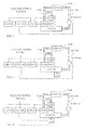
FIG 1 is a schematic view showing the main system structure of the foundational theories according to the present invention. -
FIG. 2 is a schematic view showing the system structure ofFIG 1 being further installed with a temperature detector (TD100). -
FIG 3 is a schematic view showing the system structure ofFIG. 1 being further installed with a liquid refrigerant detector (HD100). -
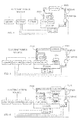
FIG. 4 is a schematic view showing the system structure ofFIG 1 being further installed with a temperature detector (TD100) and a liquid refrigerant detector (HD100). -
FIG. 5 is a schematic view showing the system structure ofFIG 4 being further installed with a fan (F101) for blowing air flow to pass through the evaporator (EVA100). -
FIG 6 is a schematic view showing the system structure ofFIG 4 being further installed with a fan (F101) for blowing air flow to pass through the evaporator (EVA100) and a fan (F102) for blowing air flow to pass through the condenser (CON 100). -
FIG 7 is a system block diagram showing the evaporator (EVA100) ofFIG 4 being further combined with a heat exchanger (HE100), -
FIG. 8 is a system block diagram showingFIG 7 being further installed with a fan (F102). -
- CD100 : Driving circuit device
- CON100 : Condenser
- ECU100 : Electric control unit
- EVA100 : Evaporator
- F101 F102 : Fan
- HD100 : Liquid refrigerant detector
- HE100 : Heat exchanger
- IJ100 : Refrigerant injector
- OID100 : Operation input device
- P100 : Pipeline
- P200 : Secondary side pipeline
- PUMP100 : Compressing pump
- R100 : Pressure-reducing regulator
- REF100 : Refrigerant
- TD100 : Temperature detector
- V100 : Switch valve
- For a conventional temperature regulation system applied in an air conditioning or freezing device, e.g. an integral or separation type cold/warm air conditioner, icy water type air conditioner, refrigerator and freezers or in a regulation device for lowering/increasing temperature or dehumidifying, the method of transporting refrigerant into an evaporator is to flow through a regulation coil or regulation valve so as to be passively sucked into the evaporator, the diffusion level and uniformity thereof are mostly poor;
- The present invention provides a temperature regulation system with hybrid refrigerant supply and regulation wherein a pressure-reducing regulator (R100) from the evaporator (EVA100) being controlled by a switch valve (V100) is installed between a condenser (CON 100) and a evaporator (EVA100), and a refrigerant injector (IJ100) is installed between the condenser (CON 100) and the evaporator (EVA 100), and an electric control unit (ECU100) is provided for controlling the switch valve (V100) and the pressure-reducing regulator (R100) or for controlling the refrigerant injector (IJ100), such that both or at least one thereof is served to transport the refrigerant (REF100) to the interior or exterior of the evaporator (EVA100);
- In the aspect of structure, after the refrigerant of a conventional dry-expansion type evaporator absorbs the thermal energy of icy water in a copper pipe, the refrigerant would become over-heating gas and return to the compressor, the icy water enters an enclosure and covers the exterior of the copper pipe; a flooded type evaporator is the evaporator having the refrigerant filled at the interior and the exterior, the refrigerant at the enclosure side maintains at a certain liquid level, wherein the refrigerant absorbs the thermal energy of icy water for being evaporated to gaseous refrigerant and returned to the compressor; a spray type evaporator utilizes a means of injecting the liquid refrigerant on a compressor for forming a flowing film which can be used to absorb the thermal energy of icy water for being evaporated to gaseous refrigerant and returned to the compressor; a falling type evaporator allows the liquid refrigerant in a dripping, columnar or sheet-like state to downwardly flow, so bubbles formed by evaporating the refrigerant are driven by the gravity of liquid refrigerant so as to downwardly move along with the liquid refrigerant.
- The present invention discloses a temperature regulation system with hybrid refrigerant supply and regulation, in which the refrigerant is injected by a refrigerant injector (IJ100) for allowing the refrigerant to be in a small particle or fine mist state and injected to the interior or exterior of an evaporator (EVA100), such that the refrigerant in the small particle or fine mist state is enabled to be accelerated for being injected to the surface of the evaporator (EVA100) thereby being diffused to films and evaporated, and forcing the gaseous refrigerant, which has already been evaporated, to be away from the surface of the evaporator (EVA100).
- The present invention provides a temperature regulation system with hybrid refrigerant supply and regulation capable of being applied in an air conditioning or freezing device, e.g. an integral or separation type cold/warm air conditioner, icy water type air conditioner, refrigerator and freezers or in a regulation device for lowering/increasing temperature or dehumidifying, in which a conventional pressure-reducing regulator (R100) being in series connected with a switch valve (V100) is parallel connected with a refrigerant injector (IJ100) and are both installed between the fluid outlet of the condenser (CON100) and an evaporator
- (EVA 100), so the temperature regulation system with hybrid refrigerant supply and regulation is structured; and through settings of an operation input device (OID100) and control and regulation of an electric control unit (ECU100) and an driving circuit device (CD100), the following modes for supplying and regulating the refrigerant (REF100) to the evaporator (EVA100) can be achieved which include: 1) closing the switch valve (V100) and the refrigerant injector (IJ101) actively injecting the refrigerant (REF100) into the evaporator (EVA100); 2) controlling the switch valve (V100) to open for supplying the refrigerant (REF100) to the evaporator (EVA100) through the pressure-reducing regulator (R100); 3) alternatively utilizing the mode 1) and the mode 2) to supply the refrigerant (REF 100) to the evaporator (EVA100); or 4) synchronously utilizing the mode 1) and the mode 2) to supply the refrigerant (REF100) to the evaporator (EVA100).
- According to this invention, embodiments of the temperature regulation system with hybrid refrigerant supply and regulation are as followings:
-
FIG. 1 is a schematic view showing the main system structure of the foundational theories according to the present invention; - As shown in
FIG 1 , it main consists of:- --Operation input device (OID100): constituted by manually-operated electromechanical interfaces or by circuit devices for inputting analog or digital operation signals, and provided for controlling the system to be actuated or stopped, selecting the operation modes, regulating temperature settings, and setting the wind output level while a fan being installed;
- --Electric control unit (ECU100): constituted by electromechanical operation devices, solid electric circuit devices and micro processers and related softwares, and provided for receiving commands sent by the operation input device (OID100) to operate the driving circuit device (CD 100) so as to control the operation schedules and operation modes of the switch valve (V100) and the pressure-reducing regulator (R100) and the refrigerant injector (IJ100);
- --Driving circuit device (CD100): receiving control signals from the electric control unit (ECU100) to control the switch valve (V100), so as to control the pressure-reducing regulator (R100) to transport the refrigerant (REF100), which is in a liquid state, from the condenser (CON100) into the evaporator (EVA100) or to terminate the transportation, and to control and drive the refrigerant injector (IJ100) to inject the liquid refrigerant (REF100) from the condenser (CON 100) to the interior or exterior of the evaporator (EVA100) in a small particle state or fine mist state according to the direction of fixed or periodical scan with respect to the operation driving and the set amount of pressurized injection and the set intensity, or to terminate the injection of the refrigerant injector (IJ100);
- --Refrigerant injector (IJ100): constituted by a device having active pressurizing injection function driven by mechanical forces, electromagnetic forces, magnetostriction or piezoelectric effects, and provided for being combined with the evaporator (EVA 100) or being in a integrated structure with the evaporator (EVA100), for receiving the operation driving of the driving circuit device (CD100) to inject the liquid refrigerant (REF100) from the condenser (CON100) to the interior or exterior of the evaporator (EVA100) in a small particle state or fine mist state according to the direction of fixed or periodical scan with respect to the operation driving and the set amount of pressurized injection and the set intensity;
- --Evaporator (EVA100): constituted by a material with good heat conductivity, in which a space structure is formed for allowing a fluid to pass through; the evaporator (EVA100) is installed with a refrigerant injector (IJ100) for communicating with the condenser (CON100), and is installed with a switch valve (V100) and a pressure-reducing regulator (R100) in series connection for allowing to be communicated with the condenser (CON100), such that the refrigerant (REF100) from the condenser (CON100) is able to be injected into the evaporator (EVA100), and is further installed with an outlet for discharging the refrigerant (REF100) which has been evaporated to the gas state or for discharging the liquid refrigerant (REF100) which has not completely been evaporated;
- --Compressing pump (PUMP100): constituted by a fluid compressing pump rotationally or reciprocally driven by mechanical forces, motor powers, or fluid motors, or engines or electromagnetic coils, and provided for compressing the gas refrigerant (REF100) from the evaporator (EVA100) to the condenser (CON 100) for being transformed to the liquid state;
- --Condenser (CON100): constituted by a material with good heat conductivity, in which a pipeline structure is provided for allowing the refrigerant (REF100) to pass through;
- --Pressure-reducing regulator (R100): constituted by an expansion valve or capillary device or liquid level controlling device, and being in series connected with the switch valve (V 100) then in parallel connected to the refrigerant injector (IJ100) between the condenser (CON100) and the evaporator (EVA100), for reducing pressure and regulating the refrigerant from the condenser (CON100);
- --Switch valve (V100): constituted by a fluid switch valve controlled by manual forces or mechanical forces or fluid forces or electromagnetic forces, and being in series connected with the pressure-reducing regulator (R100) then in parallel connected to the refrigerant injector (IJ100) between the condenser (CON100) and the evaporator (EVA100), for being controlled by the driving circuit device (CD100) so as to be opened or closed;
- --Pipelines (P100): providing for connecting the mentioned refrigerant injector (IJ100), the pressure-reducing regulator (R100), the switch valve (V100), the evaporator (EVA100), the compressing pump (PUMP100) and the condenser (CON100) for allowing the refrigerant (REF100) to circulate therein;
- In the mentioned temperature regulation system with hybrid refrigerant supply and regulation, through settings of the operation input device (OID100) and the control and regulation of the electric control unit (ECU100) and the driving circuit device (CD100), the following modes for supplying and regulating the refrigerant (REF100) to the evaporator
- (EVA100) can be achieved which include: 1) closing the switch valve (V100) and the refrigerant injector (IJ101) actively injecting the refrigerant (REF100) into the evaporator (EVA100); 2) controlling the switch valve (V100) to open for supplying the refrigerant (REF100) to the evaporator (EVA100) through the pressure-reducing regulator (R100); 3) alternatively utilizing the mode 1) and the mode 2) to supply the refrigerant (REF100) to the evaporator (EVA100); or 4) synchronously utilizing the mode 1) and the mode 2) to supply the refrigerant (REF100) to the evaporator (EVA100).
-
FIG 2 is a schematic view showing the system structure ofFIG. 1 being further installed with a temperature detector (TD100); - As shown in
FIG 2 , it main consists of: - --Operation input device (OID100): constituted by manually-operated electromechanical interfaces or by circuit devices for inputting analog or digital operation signals, and provided for controlling the system to be actuated or stopped, selecting the operation modes, regulating temperature settings, and setting the wind output level while a fan being installed;
- --Temperature detector (TD100): provided for detecting the temperature generated by the evaporator and transferring to the electric control unit (ECU100);
- --Electric control unit (ECU100): constituted by electromechanical operation devices, solid electric circuit devices and micro processers and related softwares, and provided for receiving commands sent by the operation input device (OID100) and the detected signals sent by the temperature detector (TD100) to operate the driving circuit device (CD100) so as to control the operation schedules and operation modes of the switch valve (V100) and the pressure-reducing regulator (R100) and the refrigerant injector (IJ100);
- --Driving circuit device (CD100): receiving control signals from the electric control unit (ECU100) to control the switch valve (V100), so as to control the pressure-reducing regulator (R100) to transport the refrigerant (REF100), which is in a liquid state, from the condenser (CON100) into the evaporator (EVA100) or to terminate the transportation, and to control and drive the refrigerant injector (IJ100) to inject the liquid refrigerant (REF100) from the condenser (CON100) to the interior or exterior of the evaporator (EVA100) in a small particle state or fine mist state according to the direction of fixed or periodical scan with respect to the operation driving and the set amount of pressurized injection and the set intensity, or to terminate the injection of the refrigerant injector (IJ 100);
- --Refrigerant injector (IJ100): constituted by a device having active pressurizing injection function driven by mechanical forces, electromagnetic forces, magnetostriction or piezoelectric effects, and provided for being combined with the evaporator (EVA100) or being in a integrated structure with the evaporator (EVA100), for receiving the operation driving of the driving circuit device (CD100) to inject the liquid refrigerant (REF100) from the condenser (CON100) to the interior or exterior of the evaporator (EVA100) in a small particle state or fine mist state according to the direction of fixed or periodical scan with respect to the operation driving and the set amount of pressurized injection and the set intensity;
- --Evaporator (EVA100): constituted by a material with good heat conductivity, in which a space structure is formed for allowing a fluid to pass through; the evaporator (EVA100) is installed with a refrigerant injector (IJ100) for communicating with the condenser (CON100), and is installed with a switch valve (V100) and a pressure-reducing regulator (R100) in series connection for allowing to be communicated with the condenser (CON100), such that the refrigerant (REF100) from the condenser (CON100) is able to be injected into the evaporator (EVA100), and is further installed with an outlet for discharging the refrigerant (REF100) which has been evaporated to the gas state or for discharging the liquid refrigerant (REF100) which has not completely been evaporated;
- --Compressing pump (PUMP100): constituted by a fluid compressing pump rotationally or reciprocally driven by mechanical forces, motor powers, or fluid motors, or engines or electromagnetic coils, and provided for compressing the gas refrigerant (RFF100) from the evaporator (EVA 100) to the condenser (CON 100) for being transformed to the liquid state;
- --Condenser (CON100): constituted by a material with good heat conductivity, in which a pipeline structure is provided for allowing the refrigerant (REF100) to pass through;
- --Pressure-reducing regulator (R100): constituted by an expansion valve or capillary device or liquid level controlling device, and being in series connected with the switch valve (V100) then in parallel connected to the refrigerant injector (IJ100) between the condenser (CON 100) and the evaporator (EVA100), for reducing pressure and regulating the refrigerant from the condenser (CON 100);
- --Switch valve (V100): constituted by a fluid switch valve controlled by manual forces or mechanical forces or fluid forces or electromagnetic forces, and being in series connected with the pressure-reducing regulator (R100) then in parallel connected to the refrigerant injector (IJ100) between the condenser (CON100) and the evaporator (EVA100), for being controlled by the driving circuit device (CD100) so as to be opened or closed;
- --Pipelines (P100): providing for connecting the mentioned refrigerant injector (IJ100), the pressure-reducing regulator (R100), the switch valve (V100), the evaporator (EVA100), the compressing pump (PUMP100) and the condenser (CON100) for allowing the refrigerant (REF100) to circulate therein;
- In the mentioned temperature regulation system with hybrid refrigerant supply and regulation, through settings of the operation input device (OID100) and the control and regulation of the electric control unit (ECU100) and the driving circuit device (CD100), the following modes for supplying and regulating the refrigerant (REF100) to the evaporator (EVA100) can be achieved which include: 1) closing the switch valve (V100) and the refrigerant injector (IJ101) actively injecting the refrigerant (REF100) into the evaporator (EVA100); 2) controlling the switch valve (V100) to open for supplying the refrigerant (REF100) to the evaporator (EVA100) through the pressure-reducing regulator (R100); 3) alternatively utilizing the mode 1) and the mode 2) to supply the refrigerant (REF100) to the evaporator (EVA100); or 4) synchronously utilizing the mode 1) and the mode 2) to supply the refrigerant (REF100) to the evaporator (EVA100).
-
FIG 3 is a schematic view showing the system structure ofFIG. 1 being further installed with a liquid refrigerant detector (HD100). - As shown in
FIG 3 , it mainly consists of: - --Operation input device (OID100): constituted by manually-operated electromechanical interfaces or by circuit devices for inputting analog or digital operation signals, and provided for controlling the system to be actuated or stopped, selecting the operation modes, regulating temperature settings, and setting the wind output level while a fan being installed;
- --Electric control unit (ECU100): constituted by electromechanical operation devices, solid electric circuit devices and micro processers and related softwares, and provided for receiving commands sent by the operation input device (OID100) and the detected signals sent by the liquid refrigerant detector (HD100) to operate the driving circuit device (CD100) so as to control the operation schedules and operation modes of the switch valve (V100) and the pressure-reducing regulator (R100) and the refrigerant injector (IJ100);
- --Driving circuit device (CD100): receiving control signals from the electric control unit (ECU100) to control the switch valve (V100), so as to control the pressure-reducing regulator (R100) to transport the refrigerant (REF100), which is in a liquid state, from the condenser (CON100) into the evaporator (EVA100) or to terminate the transportation, and to control and drive the refrigerant injector (IJ100) to inject the liquid refrigerant (REF100) from the condenser (CON100) to the interior or exterior of the evaporator (EVA100) in a small particle state or fine mist state according to the direction of fixed or periodical scan with respect to the operation driving and the set amount of pressurized injection and the set intensity, or to terminate the injection of the refrigerant injector (IJ100);
- --Refrigerant injector (IJ100): constituted by a device having active pressurizing injection function driven by mechanical forces, electromagnetic forces, magnetostriction or piezoelectric effects, and provided for being combined with the evaporator (EVA100) or being in a integrated structure with the evaporator (EVA100), for receiving the operation driving of the driving circuit device (CD100) to inject the liquid refrigerant (REF100) from the condenser (CON100) to the interior or exterior of the evaporator (EVA100) in a small particle state or fine mist state according to the direction of fixed or periodical scan with respect to the operation driving and the set amount of pressurized injection and the set intensity;
- --Evaporator (EVA100): constituted by a material with good heat conductivity, in which a space structure is formed for allowing a fluid to pass through; the evaporator (EVA100) is installed with a refrigerant injector (IJ100) for communicating with the condenser (CON100), and is installed with a switch valve (V100) and a pressure-reducing regulator (R100) in series connection for allowing to be communicated with the condenser (CON100), such that the refrigerant (REF100) from the condenser (CON100) is able to be injected into the evaporator (EVA100), and is further installed with an outlet for discharging the refrigerant (REF100) which has been evaporated to the gas state or for discharging the liquid refrigerant (REF100) which has not completely been evaporated;
- --Liquid refrigerant detector (HD100): installed in the evaporator (EVA100), and provided for detecting the evaporating state of the refrigerant (REF100) inside the evaporator (EVA100), when the refrigerant (REF100) is not completely evaporated and the residual liquid refrigerant (REF100) is remained, a signal is feedback to the electric control unit (ECU100) for the electric control unit (ECU 100) controlling the driving circuit device (CD100) to regulate the refrigerant injector (IJ100) for reducing the amount of refrigerant (REF100) injected into the evaporator (EVA 100);
- --Compressing pump (PUMP100): constituted by a fluid compressing pump rotationally or reciprocally driven by mechanical forces, motor powers, or fluid motors, or engines or electromagnetic coils, and provided for compressing the gas refrigerant (REF100) from the evaporator (EVA I 00) to the condenser (CON 100) for being transformed to the liquid state;
- --Condenser (CON100): constituted by a material with good heat conductivity, in which a pipeline structure is provided for allowing the refrigerant (REF100) to pass through;
- --Pressure-reducing regulator (R100): constituted by an expansion valve or capillary device or liquid level controlling device, and being in series connected with the switch valve (V100) then in parallel connected to the refrigerant injector (IJ100) between the condenser (CON100) and the evaporator (EVA100), for reducing pressure and regulating the refrigerant from the condenser (CON100);
- --Switch valve (V100): constituted by a fluid switch valve controlled by manual forces or mechanical forces or fluid forces or electromagnetic forces, and being in series connected with the pressure-reducing regulator (R100) then in parallel connected to the refrigerant injector (IJ100) between the condenser (CON100) and the evaporator (EVA100), for being controlled by the driving circuit device (CD100) so as to be opened or closed;
- --Pipelines (P100): providing for connecting the mentioned refrigerant injector (IJ100), the pressure-reducing regulator (R100), the switch valve (V100), the evaporator (EVA100), the compressing pump (PUMP100) and the condenser (CON100) for allowing the refrigerant (REF100) to circulate therein;
- In the mentioned temperature regulation system with hybrid refrigerant supply and regulation, through settings of the operation input device (OID100) and the control and regulation of the electric control unit (ECU100) and the driving circuit device (CD100), the following modes for supplying and regulating the refrigerant (REF100) to the evaporator (EVA100) can be achieved which include: 1) closing the switch valve (V100) and the refrigerant injector (IJ101) actively injecting the refrigerant (REF100) into the evaporator (EVA100); 2) controlling the switch valve (V100) to open for supplying the refrigerant (REF100) to the evaporator (EVA100) through the pressure-reducing regulator (R100); 3) alternatively utilizing the mode 1) and the mode 2) to supply the refrigerant (REF100) to the evaporator (EVA100); or 4) synchronously utilizing the mode 1) and the mode 2) to supply the refrigerant (REF100) to the evaporator (EVA100).
-
FIG. 4 is a schematic view showing the system structure ofFIG. 1 being further installed with a temperature detector (TD100) and a liquid refrigerant detector (HD100) - As shown in
FIG 4 , it mainly consists of: - --Operation input device (OID100): constituted by manually-operated electromechanical interfaces or by circuit devices for inputting analog or digital operation signals, and provided for controlling the system to be actuated or stopped, selecting the operation modes, regulating temperature settings, and setting the wind output level while a fan being installed;
- --Temperature detector (TD100): provided for detecting the temperature generated by the evaporator and transferring to the electric control unit (ECU100);
- --Electric control unit (ECU100): constituted by electromechanical operation devices, solid electric circuit devices and micro processers and related softwares, and provided for receiving commands sent by the operation input device (OID100), the detected signals sent by the liquid refrigerant detector (HD100) and the detected signals sent by the temperature detector (TD100) to operate the driving circuit device (CD100) so as to control the operation schedules and operation modes of the switch valve (V100) and the pressure-reducing regulator (R100) and the refrigerant injector (IJ100);
- --Driving circuit device (CD100): receiving control signals from the electric control unit (ECU100) to control the switch valve (V100), so as to control the pressure-reducing regulator (R100) to transport the refrigerant (REF100), which is in a liquid state, from the condenser (CON100) into the evaporator (EVA 100) or to terminate the transportation, and to control and drive the refrigerant injector (IJ100) to inject the liquid refrigerant (REF100) from the condenser (CON 100) to the interior or exterior of the evaporator (EVA 100) in a small particle state or fine mist state according to the direction of fixed or periodical scan with respect to the operation driving and the set amount of pressurized injection and the set intensity, or to terminate the injection of the refrigerant injector (IJ100);
- --Refrigerant injector (IJ100): constituted by a device having active pressurizing injection function driven by mechanical forces, electromagnetic forces, magnetostriction or piezoelectric effects, and provided for being combined with the evaporator (EVA100) or being in a integrated structure with the evaporator (EVA100), for receiving the operation driving of the driving circuit device (CD100) to inject the liquid refrigerant (REF100) from the condenser (CON100) to the interior or exterior of the evaporator (EVA100) in a small particle state or fine mist state according to the direction of fixed or periodical scan with respect to the operation driving and the set amount of pressurized injection and the set intensity;
- --Evaporator (EVA100): constituted by a material with good heat conductivity, in which a space structure is formed for allowing a fluid to pass through; the evaporator (EVA100) is installed with a refrigerant injector (IJ100) for communicating with the condenser (CON100), and is installed with a switch valve (V100) and a pressure-reducing regulator (R100) in series connection for allowing to be communicated with the condenser (CON100), such that the refrigerant (REF100) from the condenser (CON100) is able to be injected into the evaporator (EVA100), and is further installed with an outlet for discharging the refrigerant (REF100) which has been evaporated to the gas state or for discharging the liquid refrigerant (REF100) which has not completely been evaporated;
- --Liquid refrigerant detector (HD100): installed in the evaporator (EVA100), and provided for detecting the evaporating state of the refrigerant (REF100) inside the evaporator (EVA100), when the refrigerant (REF100) is not completely evaporated and the residual liquid refrigerant (REF100) is remained, a signal is feedback to the electric control unit (ECU100) for the electric control unit (ECU100) controlling the driving circuit device (CD100) to regulate the refrigerant injector (IJ100) for reducing the amount of refrigerant (REF100) injected into the evaporator (EVA100);
- --Compressing pump (PUMP100): constituted by a fluid compressing pump rotationally or reciprocally driven by mechanical forces, motor powers, or fluid motors, or engines or electromagnetic coils, and provided for compressing the gas refrigerant (REF100) from the evaporator (EVA 100) to the condenser (CON100) for being transformed to the liquid state;
- --Condenser (CON100): constituted by a material with good heat conductivity, in which a pipeline structure is provided for allowing the refrigerant (REF100) to pass through;
- --Pressure-reducing regulator (R100): constituted by an expansion valve or capillary device or liquid level controlling device, and being in series connected with the switch valve (V100) then in parallel connected to the refrigerant injector (IJ100) between the condenser (CON100) and the evaporator (EVA100), for reducing pressure and regulating the refrigerant from the condenser (CON 100);
- --Switch valve (V100): constituted by a fluid switch valve controlled by manual forces or mechanical forces or fluid forces or electromagnetic forces, and being in series connected with the pressure-reducing regulator (R100) then in parallel connected to the refrigerant injector (IJ100) between the condenser (CON100) and the evaporator (EVA100), for being controlled by the driving circuit device (CD100) so as to be opened or closed;
- --Pipelines (P100): providing for connecting the mentioned refrigerant injector (IJ100), the pressure-reducing regulator (R100), the switch valve (V100), the evaporator (EVA100), the compressing pump (PUMP100) and the condenser (CON100) for allowing the refrigerant (REF100) to circulate therein;
- In the mentioned temperature regulation system with hybrid refrigerant supply and regulation, through settings of the operation input device (OID100) and the control and regulation of the electric control unit (ECU100) and the driving circuit device (CD100), the following modes for supplying and regulating the refrigerant (REF100) to the evaporator (EVA100) can be achieved which include: 1) closing the switch valve (V100) and the refrigerant injector (IJ101) actively injecting the refrigerant (REF100) into the evaporator (EVA100); 2) controlling the switch valve (V100) to open for supplying the refrigerant (REF100) to the evaporator (EVA100) through the pressure-reducing regulator (R100); 3) alternatively utilizing the mode 1) and the mode 2) to supply the refrigerant (REF100) to the evaporator (EVA100); or 4) synchronously utilizing the mode 1) and the mode 2) to supply the refrigerant (REF100) to the evaporator (EVA100).
-
FIG 5 is a schematic view showing the system structure ofFIG 4 being further installed with a fan (F101) for blowing air flow to pass through the evaporator (EVA100). - As shown in
FIG 5 , it mainly consists of: - --Operation input device (OID100): constituted by manually-operated electromechanical interfaces or by circuit devices for inputting analog or digital operation signals, and provided for controlling the system to be actuated or stopped, selecting the operation modes, regulating temperature settings, and setting the wind output level while a fan being installed;
- --Temperature detector (TD100): provided for detecting the temperature generated by the evaporator and transferring to the electric control unit (ECU100);
- --Electric control unit (ECU100): constituted by electromechanical operation devices, solid electric circuit devices and micro processers and related softwares, and provided for receiving commands sent by the operation input device (OID100), the detected signals sent by the liquid refrigerant detector (HD100) and the detected signals sent by the temperature detector (TD100) to operate the driving circuit device (CD100) so as to control the operation schedules and operation modes of the switch valve (V100) and the pressure-reducing regulator (R100) and the refrigerant injector (IJ100);
- --Driving circuit device (CD100): receiving control signals from the electric control unit (ECU100) to control the switch valve (V100), so as to control the pressure-reducing regulator (R100) to transport the refrigerant (REF100), which is in a liquid state, from the condenser (CON100) into the evaporator (EVA100) or to terminate the transportation, and to control and drive the refrigerant injector (IJ100) to inject the liquid refrigerant (REF100) from the condenser (CON100) to the interior or exterior of the evaporator (EVA100) in a small particle state or fine mist state according to the direction of fixed or periodical scan with respect to the operation driving and the set amount of pressurized injection and the set intensity, or to terminate the injection of the refrigerant injector (IJ100);
- --Refrigerant injector (IJ100): constituted by a device having active pressurizing injection function driven by mechanical forces, electromagnetic forces, magnetostriction or piezoelectric effects, and provided for being combined with the evaporator (EVA100) or being in a integrated structure with the evaporator (EVA100), for receiving the operation driving of the driving circuit device (CD100) to inject the liquid refrigerant (REF100) from the condenser (CON100) to the interior or exterior of the evaporator (EVA100) in a small particle state or fine mist state according to the direction of fixed or periodical scan with respect to the operation driving and the set amount of pressurized injection and the set intensity;
- --Evaporator (EVA100): constituted by a material with good heat conductivity, in which a space structure is formed for allowing a fluid to pass through; the evaporator (EVA100) is installed with a refrigerant injector (IJ100) for communicating with the condenser (CON100), and is installed with a switch valve (V100) and a pressure-reducing regulator (R100) in series connection for allowing to be communicated with the condenser (CON100), such that the refrigerant (REF100) from the condenser (CON100) is able to be injected into the evaporator (EVA100), and is further installed with an outlet for discharging the refrigerant (REF100) which has been evaporated to the gas state or for discharging the liquid refrigerant (REF100) which has not completely been evaporated;
- --Liquid refrigerant detector (HD100): installed in the evaporator (EVA100), and provided for detecting the evaporating state of the refrigerant (REF100) inside the evaporator (EVA100), when the refrigerant (REF100) is not completely evaporated and the residual liquid refrigerant (REF100) is remained, a signal is feedback to the electric control unit (ECU 100) for the electric control unit (ECU100) controlling the driving circuit device (CD100) to regulate the refrigerant injector (IJ100) for reducing the amount of refrigerant (REF100) injected into the evaporator (EVA100);
- --Compressing pump (PUMP100): constituted by a fluid compressing pump rotationally or reciprocally driven by mechanical forces, motor powers, or fluid motors, or engines or electromagnetic coils, and provided for compressing the gas refrigerant (REF100) from the evaporator (EVA100) to the condenser (CON100) for being transformed to the liquid state;
- --Condenser (CON100): constituted by a material with good heat conductivity, in which a pipeline structure is provided for allowing the refrigerant (REF100) to pass through;
- --Pressure-reducing regulator (R100): constituted by an expansion valve or capillary device or liquid level controlling device, and being in series connected with the switch valve (V100) then in parallel connected to the refrigerant injector (IJ100) between the condenser (CON100) and the evaporator (EVA100), for reducing pressure and regulating the refrigerant from the condenser (CON 100);
- --Switch valve (V100): constituted by a fluid switch valve controlled by manual forces or mechanical forces or fluid forces or electromagnetic forces, and being in series connected with the pressure-reducing regulator (R100) then in parallel connected to the refrigerant injector (IJ100) between the condenser (CON 100) and the evaporator (EVA100), for being controlled by the driving circuit device (CD100) so as to be opened or closed;
- --Pipelines (P100): providing for connecting the mentioned refrigerant injector (IJ100), the pressure-reducing regulator (R100), the switch valve (V100), the evaporator (EVA100), the compressing pump (PUMP100) and the condenser (CON100) for allowing the refrigerant (REF100) to circulate therein;
- --Fan (F101): constituted by a fan driven by an electric motor or the mechanical revolving force, and provided for blowing air flow to pass through the evaporator (EVA100), such that the air and the evaporator (EVA100) exchange heat then be discharged;
- In the mentioned temperature regulation system with hybrid refrigerant supply and regulation, through settings of the operation input device (OID100) and the control and regulation of the electric control unit (ECU100) and the driving circuit device (CD100), the following modes for supplying and regulating the refrigerant (REF100) to the evaporator (EVA100) can be achieved which include: 1) closing the switch valve (V100) and the refrigerant injector (IJ101) actively injecting the refrigerant (REF100) into the evaporator (EVA100); 2) controlling the switch valve (V100) to open for supplying the refrigerant (REF100) to the evaporator (EVA100) through the pressure-reducing regulator (R100); 3) alternatively utilizing the mode 1) and the mode 2) to supply the refrigerant (REF100) to the evaporator (EVA100); or 4) synchronously utilizing the mode 1) and the mode 2) to supply the refrigerant (REF100) to the evaporator (EVA100).
-
FIG 6 is a schematic view showing the system structure ofFIG. 4 being further installed with a fan (F101) for blowing air flow to pass through the evaporator (EVA100) and a fan (F102) for blowing air flow to pass through the condenser (CON 100). - As shown in
FIG 6 , it mainly consists of: - --Operation input device (OID100): constituted by manually-operated electromechanical interfaces or by circuit devices for inputting analog or digital operation signals, and provided for controlling the system to be actuated or stopped, selecting the operation modes, regulating temperature settings, and setting the wind output level while a fan being installed;
- --Temperature detector (TD100): provided for detecting the temperature generated by the evaporator and transferring to the electric control unit (ECU100);
- --Electric control unit (ECU100): constituted by electromechanical operation devices, solid electric circuit devices and micro processers and related softwares, and provided for receiving commands sent by the operation input device (OID100), the detected signals sent by the liquid refrigerant detector (HD100) and the detected signals sent by the temperature detector (TD100) to operate the driving circuit device (CD100) so as to control the operation schedules and operation modes of the switch valve (V100) and the pressure-reducing regulator (R100) and the refrigerant injector (IJ100);
- --Driving circuit device (CD100): receiving control signals from the electric control unit (ECU100) to control the switch valve (V100), so as to control the pressure-reducing regulator (R100) to transport the refrigerant (REF100), which is in a liquid state, from the condenser (CON100) into the evaporator (EVA100) or to terminate the transportation, and to control and drive the refrigerant injector (IJ100) to inject the liquid refrigerant (REF100) from the condenser (CON100) to the interior or exterior of the evaporator (EVA100) in a small particle state or fine mist state according to the direction of fixed or periodical scan with respect to the operation driving and the set amount of pressurized injection and the set intensity, or to terminate the injection of the refrigerant injector (IJ100);
- --Refrigerant injector (IJ100): constituted by a device having active pressurizing injection function driven by mechanical forces, electromagnetic forces, magnetostriction or piezoelectric effects, and provided for being combined with the evaporator (EVA100) or being in a integrated structure with the evaporator (EVA100), for receiving the operation driving of the driving circuit device (CD100) to inject the liquid refrigerant (REF100) from the condenser (CON 100) to the interior or exterior of the evaporator (EVA100) in a small particle state or fine mist state according to the direction of fixed or periodical scan with respect to the operation driving and the set amount of pressurized injection and the set intensity;
- --Evaporator (EVA100): constituted by a material with good heat conductivity, in which a space structure is formed for allowing a fluid to pass through; the evaporator (EVA100) is installed with a refrigerant injector (IJ100) for communicating with the condenser (CON100), and is installed with a switch valve (V100) and a pressure-reducing regulator (R100) in series connection for allowing to be communicated with the condenser (CON100), such that the refrigerant (REF100) from the condenser (CON 100) is able to be injected into the evaporator (EVA100), and is further installed with an outlet for discharging the refrigerant (REF100) which has been evaporated to the gas state or for discharging the liquid refrigerant (REF100) which has not completely been evaporated;
- --Liquid refrigerant detector (HD100): installed in the evaporator (EVA100), and provided for detecting the evaporating state of the refrigerant (REF100) inside the evaporator (EVA100), when the refrigerant (REF100) is not completely evaporated and the residual liquid refrigerant (REF100) is remained, a signal is feedback to the electric control unit (ECU100) for the electric control unit (ECU100) controlling the driving circuit device (CD100) to regulate the refrigerant injector (IJ100) for reducing the amount of refrigerant (REF100) injected into the evaporator (EVA 100);
- --Compressing pump (PUMP100): constituted by a fluid compressing pump rotationally or reciprocally driven by mechanical forces, motor powers, or fluid motors, or engines or electromagnetic coils, and provided for compressing the gas refrigerant (REF100) from the evaporator (EVA100) to the condenser (CON 100) for being transformed to the liquid state;
- --Condenser (CON100): constituted by a material with good heat conductivity, in which a pipeline structure is provided for allowing the refrigerant (REF100) to pass through;
- --Pressure-reducing regulator (R100): constituted by an expansion valve or capillary device or liquid level controlling device, and being in series connected with the switch valve (V100) then in parallel connected to the refrigerant injector (IJ100) between the condenser (CON100) and the evaporator (EVA100), for reducing pressure and regulating the refrigerant from the condenser (CON100);
- --Switch valve (V100): constituted by a fluid switch valve controlled by manual forces or mechanical forces or fluid forces or electromagnetic forces, and being in series connected with the pressure-reducing regulator (R100) then in parallel connected to the refrigerant injector (IJI00) between the condenser (CON100) and the evaporator (EVA100), for being controlled by the driving circuit device (CD100) so as to be opened or closed;
- --Pipelines (F100): providing for connecting the mentioned refrigerant injector (IJ100), the pressure-reducing regulator (R100), the switch valve (V100), the evaporator (EVA100), the compressing pump (PUMP100) and the condenser (CON100) for allowing the refrigerant (REF100) to circulate therein;
- --Fan (F101): constituted by a fan driven by an electric motor or the mechanical revolving force, and provided for blowing air flow to pass through the evaporator (EVA 100), such that the air and the evaporator (EVA100) exchange heat then be discharged;
- --Fan (F102): constituted by a fan driven by an electric motor or the mechanical revolving force, and provided for blowing air flow to pass through the condenser (CON100), such that the air and the condenser (CON100) exchange heat;
- In the mentioned temperature regulation system with hybrid refrigerant supply and regulation, through settings of the operation input device (OID100) and the control and regulation of the electric control unit (ECU100) and the driving circuit device (CD100), the following modes for supplying and regulating the refrigerant (REF100) to the evaporator (EVA100) can be achieved which include: 1) closing the switch valve (V100) and the refrigerant injector (IJ101) actively injecting the refrigerant (REF100) into the evaporator (EVA100); 2) controlling the switch valve (V100) to open for supplying the refrigerant (REF100) to the evaporator (EVA100) through the pressure-reducing regulator (R100); 3) alternatively utilizing the mode 1) and the mode 2) to supply the refrigerant (REF100) to the evaporator (EVA100); or 4) synchronously utilizing the mode 1) and the mode 2) to supply the refrigerant (REF 100) to the evaporator (EVA100).
-
FIG. 7 is a system block diagram showing the evaporator (EVA100) ofFIG 4 being further combined with a heat exchanger (HE100). - As shown in
FIG. 7 , it mainly consists of: - --Operation input device (OID100): constituted by manually-operated electromechanical interfaces or by circuit devices for inputting analog or digital operation signals, and provided for controlling the system to be actuated or stopped, selecting the operation modes, regulating temperature settings, and setting the wind output level while a fan being installed;
- --Temperature detector (TD100): provided for detecting the temperature generated by the evaporator and transferring to the electric control unit (ECU100);
- --Electric control unit (ECU100): constituted by electromechanical operation devices, solid electric circuit devices and micro processers and related softwares, and provided for receiving commands sent by the operation input device (OID100), the detected signals sent by the liquid refrigerant detector (HD100) and the detected signals sent by the temperature detector (TD100) to operate the driving circuit device (CD100) so as to control the operation schedules and operation modes of the switch valve (V100) and the pressure-reducing regulator (R100) and the refrigerant injector (IJ100);
- --Driving circuit device (CD100): receiving control signals from the electric control unit (ECU100) to control the switch valve (V100), so as to control the pressure-reducing regulator (R100) to transport the refrigerant (REF100), which is in a liquid state, from the condenser (CON100) into the evaporator (EVA100) or to terminate the transportation, and to control and drive the refrigerant injector (IJ100) to inject the liquid refrigerant (REF100) from the condenser (CON100) to the interior or exterior of the evaporator (EVA 100) in a small particle state or fine mist state according to the direction of fixed or periodical scan with respect to the operation driving and the set amount of pressurized injection and the set intensity, or to terminate the injection of the refrigerant injector (IJ100);
- --Refrigerant injector (IJ100): constituted by a device having active pressurizing injection function driven by mechanical forces, electromagnetic forces, magnetostriction or piezoelectric effects, and provided for being combined with the evaporator (EVA100) or being in a integrated structure with the evaporator (EVA100), for receiving the operation driving of the driving circuit device (CD100) to inject the liquid refrigerant (REF100) from the condenser (CON 100) to the interior or exterior of the evaporator (EVA100) in a small particle state or fine mist state according to the direction of fixed or periodical scan with respect to the operation driving and the set amount of pressurized injection and the set intensity;
- --Evaporator (EVA100): constituted by a material with good heat conductivity, in which a space structure is formed for allowing a fluid to pass through; the evaporator (EVA100) is installed with a refrigerant injector (IJ100) for communicating with the condenser (CON100), and is installed with a switch valve (V100) and a pressure-reducing regulator (R100) in series connection for allowing to be communicated with the condenser (CON100), such that the refrigerant (REF100) from the condenser (CON100) is able to be injected into the evaporator (EVA100), and is further installed with an outlet for discharging the refrigerant (REF100) which has been evaporated to the gas state or for discharging the liquid refrigerant (REF100) which has not completely been evaporated;
- --Liquid refrigerant detector (HD100): installed in the evaporator (EVA100), and provided for detecting the evaporating state of the refrigerant (REF100) inside the evaporator (EVA 100), when the refrigerant (REF100) is not completely evaporated and the residual liquid refrigerant (REF100) is remained, a signal is feedback to the electric control unit (ECU100) for the electric control unit (ECU100) controlling the driving circuit device (CD100) to regulate the refrigerant injector (IJ100) for reducing the amount of refrigerant (REF100) injected into the evaporator (EVA100);
- --Compressing pump (PUMP100): constituted by a fluid compressing pump rotationally or reciprocally driven by mechanical forces, motor powers, or fluid motors, or engines or electromagnetic coils, and provided for compressing the gas refrigerant (REF100) from the evaporator (EVA100) to the condenser (CON100) for being transformed to the liquid state;
- --Condenser (CON100): constituted by a material with good heat conductivity, in which a pipeline structure is provided for allowing the refrigerant (REF100) to pass through;
- --Pressure-reducing regulator (R100): constituted by an expansion valve or capillary device or liquid level controlling device, and being in series connected with the switch valve (V100) then in parallel connected to the refrigerant injector (IJ100) between the condenser (CON100) and the evaporator (EVA100), for reducing pressure and regulating the refrigerant from the condenser (CON 100);
- --Switch valve (V100): constituted by a fluid switch valve controlled by manual forces or mechanical forces or fluid forces or electromagnetic forces, and being in series connected with the pressure-reducing regulator (R100) then in parallel connected to the refrigerant injector (IJ100) between the condenser (CON100) and the evaporator (EVA100), for being controlled by the driving circuit device (CD100) so as to be opened or closed;
- --Pipelines (P100): providing for connecting the mentioned refrigerant injector (IJ100), the pressure-reducing regulator (R100), the switch valve (V100), the evaporator (EVA100), the compressing pump (PUMF100) and the condenser (CON100) for allowing the refrigerant (REF100) to circulate therein;
- --Heat exchanger (HE100): constituted by a primary side evaporator (EVA100) and a secondary side pipeline (P200) to be in a structure of being combined with each other for transferring thermal energy;
- --Secondary side pipeline (P200): served as a secondary side pipeline for the heat exchanger (HE100) and allowing gas or liquid fluid to pass through;
- In the mentioned temperature regulation system with hybrid refrigerant supply and regulation, through settings of the operation input device (OID100) and the control and regulation of the electric control unit (ECU100) and the driving circuit device (CD100), the following modes for supplying and regulating the refrigerant (REF100) to the evaporator (EVA100) can be achieved which include: 1) closing the switch valve (V100) and the refrigerant injector (IJ101) actively injecting the refrigerant (REF100) into the evaporator (EVA100); 2) controlling the switch valve (V100) to open for supplying the refrigerant (REF100) to the evaporator (EVA100) through the pressure-reducing regulator (R100); 3) alternatively utilizing the mode 1) and the mode 2) to supply the refrigerant (REF100) to the evaporator (EVA100); or 4) synchronously utilizing the mode 1) and the mode 2) to supply the refrigerant (REF100) to the evaporator (EVA100).
-
FIG 8 is a system block diagram showingFIG 7 being further installed with a fan (F102). - As shown in
FIG. 8 , it mainly consists of: - --Operation input device (OID100): constituted by manually-operated electromechanical interfaces or by circuit devices for inputting analog or digital operation signals, and provided for controlling the system to be actuated or stopped, selecting the operation modes, regulating temperature settings, and setting the wind output level while a fan being installed;
- --Temperature detector (TD100): provided for detecting the temperature generated by the evaporator and transferring to the electric control unit (ECU100);
- --Electric control unit (ECU100): constituted by electromechanical operation devices, solid electric circuit devices and micro processers and related softwares, and provided for receiving commands sent by the operation input device (OID100), the detected signals sent by the liquid refrigerant detector (HD100) and the detected signals sent by the temperature detector (TD100) to operate the driving circuit device (CD100) so as to control the operation schedules and operation modes of the switch valve (V100) and the pressure-reducing regulator (R100) and the refrigerant injector (IJ100);
- --Driving circuit device (CD100): receiving control signals from the electric control unit (ECU100) to control the switch valve (V100), so as to control the pressure-reducing regulator (R100) to transport the refrigerant (REF100), which is in a liquid state, from the condenser (CON100) into the evaporator (EVA100) or to terminate the transportation, and to control and drive the refrigerant injector (IJ100) to inject the liquid refrigerant (REF100) from the condenser (CON100) to the interior or exterior of the evaporator (EVA100) in a small particle state or fine mist state according to the direction of fixed or periodical scan with respect to the operation driving and the set amount of pressurized injection and the set intensity, or to terminate the injection of the refrigerant injector (IJ100);
- --Refrigerant injector (IJ100): constituted by a device having active pressurizing injection function driven by mechanical forces, electromagnetic forces, magnetostriction or piezoelectric effects, and provided for being combined with the evaporator (EVA100) or being in a integrated structure with the evaporator (EVA 100), for receiving the operation driving of the driving circuit device (CD100) to inject the liquid refrigerant (REF100) from the condenser (CON100) to the interior or exterior of the evaporator (EVA100) in a small particle state or fine mist state according to the direction of fixed or periodical scan with respect to the operation driving and the set amount of pressurized injection and the set intensity;
- --Evaporator (EVA100): constituted by a material with good heat conductivity, in which a space structure is formed for allowing a fluid to pass through; the evaporator (EVA100) is installed with a refrigerant injector (IJ100) for communicating with the condenser (CON100), and is installed with a switch valve (V100) and a pressure-reducing regulator (R100) in series connection for allowing to be communicated with the condenser (CON100), such that the refrigerant (REF100) from the condenser (CON100) is able to be injected into the evaporator (EVA100), and is further installed with an outlet for discharging the refrigerant (REF100) which has been evaporated to the gas state or for discharging the liquid refrigerant (REF100) which has not completely been evaporated;
- --Liquid refrigerant detector (HD100): installed in the evaporator (EVA100), and provided for detecting the evaporating state of the refrigerant (REF 100) inside the evaporator (EVA 100), when the refrigerant (REF100) is not completely evaporated and the residual liquid refrigerant (REF 100) is remained, a signal is feedback to the electric control unit (ECU100) for the electric control unit (ECU100) controlling the driving circuit device (CD100) to regulate the refrigerant injector (IJ100) for reducing the amount of refrigerant (REF100) injected into the evaporator (EVA100);
- --Compressing pump (PUMP100): constituted by a fluid compressing pump rotationally or reciprocally driven by mechanical forces, motor powers, or fluid motors, or engines or electromagnetic coils, and provided for compressing the gas refrigerant (REF100) from the evaporator (EVA100) to the condenser (CON100) for being transformed to the liquid state;
- --Condenser (CON100): constituted by a material with good heat conductivity, in which a pipeline structure is provided for allowing the refrigerant (REF100) to pass through;
- --Pressure-reducing regulator (R100): constituted by an expansion valve or capillary device or liquid level controlling device, and being in series connected with the switch valve (V100) then in parallel connected to the refrigerant injector (IJ100) between the condenser (CON100) and the evaporator (EVA100), for reducing pressure and regulating the refrigerant from the condenser (CON 100);
- --Switch valve (V100): constituted by a fluid switch valve controlled by manual forces or mechanical forces or fluid forces or electromagnetic forces, and being in series connected with the pressure-reducing regulator (R100) then in parallel connected to the refrigerant injector (IJ100) between the condenser (CON100) and the evaporator (EVA 100), for being controlled by the driving circuit device (CD100) so as to be opened or closed;
- --Pipelines (P100): providing for connecting the mentioned refrigerant injector (IJ100), the pressure-reducing regulator (R100), the switch valve (V100), the evaporator (EVA100), the compressing pump (PUMP100) and the condenser (CON100) for allowing the refrigerant (REF100) to circulate therein;
- --Heat exchanger (HE100): constituted by a primary side evaporator (EVA100) and a secondary side pipeline (P200) to be in a structure of being combined with each other for transferring thermal energy;
- --Secondary side pipeline (P200): served as a secondary side pipeline for the heat exchanger (HE100) and allowing gas or liquid fluid to pass through;
- --Fan (F102): constituted by a fan driven by an electric motor or the mechanical revolving force, and provided for blowing air flow to pass through the condenser (CON100), such that the air and the condenser (CON100) exchange heat;
- In the mentioned temperature regulation system with hybrid refrigerant supply and regulation, through settings of the operation input device (OID100) and the control and regulation of the electric control unit (ECU100) and the driving circuit device (CD100), the following modes for supplying and regulating the refrigerant (REF100) to the evaporator (EVA100) can be achieved which include: 1) closing the switch valve (V100) and the refrigerant injector (IJ101) actively injecting the refrigerant (REF100) into the evaporator (EVA100); 2) controlling the switch valve (V100) to open for supplying the refrigerant (REF100) to the evaporator (EVA100) through the pressure-reducing regulator (R100); 3) alternatively utilizing the mode 1) and the mode 2) to supply the refrigerant (REF100) to the evaporator (EVA100); or 4) synchronously utilizing the mode 1) and the mode 2) to supply the refrigerant (REF 100) to the evaporator (EVA100).
- According to the temperature regulation system with hybrid refrigerant supply and regulation of this invention, mode selections include a mode with single supply and regulation set by the operation input device (OID100) for supplying the refrigerant to the evaporator (EVA100), or several modes being mixed and operated.
- According to the temperature regulation system with hybrid refrigerant supply and regulation of this invention, modes of supplying the refrigerant to the evaporator (EVA100) comprise one or more than one of the followings which include:
- 1) closing the switch valve (V100) and the refrigerant injector (IJ101) actively injecting the refrigerant (REF100) into the evaporator (EVA100); or
- 2) controlling the switch valve (V100) to open for supplying the refrigerant (REF100) to the evaporator (EVA100) through the pressure-reducing regulator (R100); or
- 3) alternatively utilizing the mode 1) and the mode 2) to supply the refrigerant (REF 100) to the evaporator (EVA100); or
- 4) synchronously utilizing the mode 1) and the mode 2) to supply the refrigerant (REF100) to the evaporator (EVA100).
- In practical applications, the structures of the temperature regulation system with hybrid refrigerant supply and regulation provided by the present invention are as followings:
- According to the temperature regulation system with hybrid refrigerant supply and regulation of this invention, the quantity of the refrigerant injector (IJ100) installed on the evaporator (EVA100) is one or more than one.
- According to the temperature regulation system with hybrid refrigerant supply and regulation of this invention, the evaporator (EVA100) and the refrigerant injector (IJ100) are individually structured or integrally structured.
- According to the temperature regulation system with hybrid refrigerant supply and regulation of this invention, the series-connected switch valve (V100) and the pressure-reducing regulator (R100) installed between the evaporator (EVA 100) and the fluid outlet of the condenser (CON 100) includes one or more than one series-connected combinations.
- According to the temperature regulation system with hybrid refrigerant supply and regulation of this invention, the switch valve (V100) and the pressure-reducing regulator (R100) are individually structured or integrally structured.
- According to the temperature regulation system with hybrid refrigerant supply and regulation of this invention, the evaporator (EVA100), the refrigerant injector (IJ100), the switch valve (V100) and the pressure-reducing regulator (R100) are individually structured or two or more than two thereof are integrally structured.
- According to the temperature regulation system with hybrid refrigerant supply and regulation of this invention, the driving circuit device (CD100) can further control the refrigerant injected by the refrigerant injector (IJ100) to be in a column-shaped liquid state or small particle state or fine mist state.
- According to the temperature regulation system with hybrid refrigerant supply and regulation of this invention, the driving circuit device (CD100) can further control the injection direction of the refrigerant injector (IJ100) which includes continuous or intermittence or periodical scan in variable injection directions.
- The temperature regulation system with hybrid refrigerant supply and regulation includes being applied in an integral or separation type cold/warm air conditioner, icy water type air conditioner, refrigerator, freezers or in a regulation device for lowering/increasing temperature or dehumidifying.
Claims (16)
- A temperature regulation system with hybrid refrigerant supply and regulation in which a pressure-reducing regulator (R100) from an evaporator (EVA100) controlled by a switch valve (V100) being installed between a condenser (CON 100) and the evaporator (EVA100), and a refrigerant injector (IJ100) being installed between the condenser (CON 100) and the evaporator (EVA100), and an electric control unit (ECU 100) being provided for controlling the switch valve (V100) and the pressure-reducing regulator (R100) or for controlling the refrigerant injector (IJ100) such that both or at least one thereof being served to transport the refrigerant (REF100) to the interior or exterior of the evaporator (EVA100);In said temperature regulation system with hybrid refrigerant supply and regulation, the refrigerant is injected by a refrigerant injector (IJ100) for allowing the refrigerant to be in a small particle or fine mist state and injected to the interior or exterior of an evaporator (EVA100), such that the refrigerant in the small particle or fine mist state is enabled to be accelerated for being injected to the surface of the evaporator (EVA 100) thereby being diffused to films and evaporated, and forcing the gaseous refrigerant, which has already been evaporated, to be away from the surface of the evaporator (EVA100); wherein it mainly consists of:--Operation input device (OID100): constituted by manually-operated electromechanical interfaces or by circuit devices for inputting analog or digital operation signals, and provided for controlling the system to be actuated or stopped, selecting the operation modes, regulating temperature settings, and setting the wind output level while a fan being installed;--Electric control unit (ECU100): constituted by electromechanical operation devices, solid electric circuit devices and micro processers and related softwares, and provided for receiving commands sent by the operation input device (OID100) to operate the driving circuit device (CD100) so as to control the operation schedules and operation modes of the switch valve (V100) and the pressure-reducing regulator (R100) and the refrigerant injector (IJ100);--Driving circuit device (CD100): receiving control signals from the electric control unit (ECU100) to control the switch valve (V100), so as to control the pressure-reducing regulator (R100) to transport the refrigerant (REF100), which is in a liquid state, from the condenser (CON100) into the evaporator (EVA100) or to terminate the transportation, and to control and drive the refrigerant injector (IJ100) to inject the liquid refrigerant (REF100) from the condenser (CON100) to the interior or exterior of the evaporator (EVA100) in a small particle state or fine mist state according to the direction of fixed or periodical scan with respect to the operation driving and the set amount of pressurized injection and the set intensity, or to terminate the injection of the refrigerant injector (IJ100);--Refrigerant injector (IJ100): constituted by a device having active pressurizing injection function driven by mechanical forces, electromagnetic forces, magnetostriction or piezoelectric effects, and provided for being combined with the evaporator (EVA100) or being in a integrated structure with the evaporator (EVA100), for receiving the operation driving of the driving circuit device (CD100) to inject the liquid refrigerant (REF100) from the condenser (CON100) to the interior or exterior of the evaporator (EVA100) in a small particle state or fine mist state according to the direction of fixed or periodical scan with respect to the operation driving and the set amount of pressurized injection and the set intensity;--Evaporator (EVA100): constituted by a material with good heat conductivity, in which a space structure is formed for allowing a fluid to pass through; the evaporator (EVA100) is installed with a refrigerant injector (IJ100) for communicating with the condenser (CON100), and is installed with a switch valve (V100) and a pressure-reducing regulator (R100) in series connection for allowing to be communicated with the condenser (CON100), such that the refrigerant (REF100) from the condenser (CON100) is able to be injected into the evaporator (EVA100), and is further installed with an outlet for discharging the refrigerant (REF100) which has been evaporated to the gas state or for discharging the liquid refrigerant (REF 100) which has not completely been evaporated;--Compressing pump (PUMP100): constituted by a fluid compressing pump rotationally or reciprocally driven by mechanical forces, motor powers, or fluid motors, or engines or electromagnetic coils, and provided for compressing the gas refrigerant (REF100) from the evaporator (EVA100) to the condenser (CON100) for being transformed to the liquid state;--Condenser (CON100): constituted by a material with good heat conductivity, in which a pipeline structure is provided for allowing the refrigerant (REF100) to pass through;--Pressure-reducing regulator (R100): constituted by an expansion valve or capillary device or liquid level controlling device, and being in series connected with the switch valve (V100) then in parallel connected to the refrigerant injector (IJ100) between the condenser (CON100) and the evaporator (EVA100), for reducing pressure and regulating the refrigerant from the condenser (CON100);--Switch valve (V100): constituted by a fluid switch valve controlled by manual forces or mechanical forces or fluid forces or electromagnetic forces, and being in series connected with the pressure-reducing regulator (R100) then in parallel connected to the refrigerant injector (IJ100) between the condenser (CON100) and the evaporator (EVA100), for being controlled by the driving circuit device (CD100) so as to be opened or closed;--Pipelines (P100): providing for connecting the mentioned refrigerant injector (IJ100), the pressure-reducing regulator (R100), the switch valve (V100), the evaporator (EVA100), the compressing pump (PUMP100) and the condenser (CUN100) for allowing the refrigerant (REF 100) to circulate therein;wherein in the mentioned temperature regulation system with hybrid refrigerant supply and regulation, through settings of the operation input device (OID100) and the control and regulation of the electric control unit (ECU 100) and the driving circuit device (CD100), the following modes for supplying and regulating the refrigerant (REF100) to the evaporator (EVA100) can be achieved which include: 1) closing the switch valve (V100) and the refrigerant injector (IJ101) actively injecting the refrigerant (REF100) into the evaporator (EVA100); 2) controlling the switch valve (V100) to open for supplying the refrigerant (REF100) to the evaporator (EVA100) through the pressure-reducing regulator (R100); 3) alternatively utilizing the mode 1) and the mode 2) to supply the refrigerant (REF100) to the evaporator (EVA100); or 4) synchronously utilizing the mode 1) and the mode 2) to supply the refrigerant (REF100) to the evaporator (EVA100).
- The temperature regulation system with hybrid refrigerant supply and regulation according to claim 1 is further installed with a temperature detector (TD100), wherein it mainly consists of:--Operation input device (OID100): constituted by manually-operated electromechanical interfaces or by circuit devices for inputting analog or digital operation signals, and provided for controlling the system to be actuated or stopped, selecting the operation modes, regulating temperature settings, and setting the wind output level while a fan being installed;--Temperature detector (TD100): provided for detecting the temperature generated by the evaporator and transferring to the electric control unit ((ECU100);--Electric control unit (ECU100): constituted by electromechanical operation devices, solid electric circuit devices and micro processers and related softwares, and provided for receiving commands sent by the operation input device (OID100) and the detected signals sent by the temperature detector (TD100) to operate the driving circuit device (CD100) so as to control the operation schedules and operation modes of the switch valve (V100) and the pressure-reducing regulator (R100) and the refrigerant injector (IJ100);--Driving circuit device (CD100): receiving control signals from the electric control unit (ECU100) to control the switch valve (V100), so as to control the pressure-reducing regulator (R100) to transport the refrigerant (REF100), which is in a liquid state, from the condenser (CON100) into the evaporator (EVA100) or to terminate the transportation, and to control and drive the refrigerant injector (IJ100) to inject the liquid refrigerant (REF100) from the condenser (CON100) to the interior or exterior of the evaporator (EVA100) in a small particle state or fine mist state according to the direction of fixed or periodical scan with respect to the operation driving and the set amount of pressurized injection and the set intensity, or to terminate the injection of the refrigerant injector (IJ100);--Refrigerant injector (IJ100): constituted by a device having active pressurizing injection function driven by mechanical forces, electromagnetic forces, magnetostriction or piezoelectric effects, and provided for being combined with the evaporator (EVA100) or being in a integrated structure with the evaporator (EVA100), for receiving the operation driving of the driving circuit device (CD100) to inject the liquid refrigerant (REF100) from the condenser (CON100) to the interior or exterior of the evaporator (EVA100) in a small particle state or fine mist state according to the direction of fixed or periodical scan with respect to the operation driving and the set amount of pressurized injection and the set intensity;--Evaporator (EVA100): constituted by a material with good heat conductivity, in which a space structure is formed for allowing a fluid to pass through; the evaporator (EVA100) is installed with a refrigerant injector (IJ100) for communicating with the condenser (CON100), and is installed with a switch valve (V100) and a pressure-reducing regulator (R100) in series connection for allowing to be communicated with the condenser (CON100), such that the refrigerant (REF100) from the condenser (CON100) is able to be injected into the evaporator (EVA100), and is further installed with an outlet for discharging the refrigerant (REF100) which has been evaporated to the gas state or for discharging the liquid refrigerant (REF100) which has not completely been evaporated;--Compressing pump (PUMP100): constituted by a fluid compressing pump rotationally or reciprocally driven by mechanical forces, motor powers, or fluid motors, or engines or electromagnetic coils, and provided for compressing the gas refrigerant (REF100) from the evaporator (EVA 100) to the condenser (CON 100) for being transformed to the liquid state;--Condenser (CON100): constituted by a material with good heat conductivity, in which a pipeline structure is provided for allowing the refrigerant (REF100) to pass through;--Pressure-reducing regulator (R100): constituted by an expansion valve or capillary device or liquid level controlling device, and being in series connected with the switch valve (V100) then in parallel connected to the refrigerant injector (IJ100) between the condenser (CON100) and the evaporator (EVA100), for reducing pressure and regulating the refrigerant from the condenser (CON100);--Switch valve (V100): constituted by a fluid switch valve controlled by manual forces or mechanical forces or fluid forces or electromagnetic forces, and being in series connected with the pressure-reducing regulator (R100) then in parallel connected to the refrigerant injector (IJ100) between the condenser (CON100) and the evaporator (EVA100), for being controlled by the driving circuit device (CD100) so as to be opened or closed;--Pipelines (P100): providing for connecting the mentioned refrigerant injector (IJ100), the pressure-reducing regulator (R100), the switch valve (V100), the evaporator (EVA100), the compressing pump (PUMP100) and the condenser (CON100) for allowing the refrigerant (REF100) to circulate therein;
wherein in the mentioned temperature regulation system with hybrid refrigerant supply and regulation, through settings of the operation input device (OID100) and the control and regulation of the electric control unit (ECU100) and the driving circuit device (CD100), the following modes for supplying and regulating the refrigerant (REF100) to the evaporator (EVA100) can be achieved which include: 1) closing the switch valve (V100) and the refrigerant injector (IJ101) actively injecting the refrigerant (REF100) into the evaporator (EVA100); 2) controlling the switch valve (V100) to open for supplying the refrigerant (REF100) to the evaporator (EVA100) through the pressure-reducing regulator (R100); 3) alternatively utilizing the mode 1) and the mode 2) to supply the refrigerant (REF100) to the evaporator (EVA100); or 4) synchronously utilizing the mode 1) and the mode 2) to supply the refrigerant (REF100) to the evaporator (EVA100). - The temperature regulation system with hybrid refrigerant supply and regulation according to claim 1 is further installed with a liquid refrigerant detector (HD100) , wherein it mainly consists of:--Operation input device (OID100): constituted by manually-operated electromechanical interfaces or by circuit devices for inputting analog or digital operation signals, and provided for controlling the system to be actuated or stopped, selecting the operation modes, regulating temperature settings, and setting the wind output level while a fan being installed;--Electric control unit (ECLJ100): constituted by electromechanical operation devices, solid electric circuit devices and micro processers and related softwares, and provided for receiving commands sent by the operation input device (OID100) and the detected signals sent by the liquid refrigerant detector (HD100) to operate the driving circuit device (CD1OO) so as to control the operation schedules and operation modes of the switch valve (V100) and the pressure-reducing regulator (R100) and the refrigerant injector (IJ100);--Driving circuit device (CD100): receiving control signals from the electric control unit (ECU100) to control the switch valve (V100), so as to control the pressure-reducing regulator (R100) to transport the refrigerant (REF100), which is in a liquid state, from the condenser (CON100) into the evaporator (EVA100) or to terminate the transportation, and to control and drive the refrigerant injector (IJ100) to inject the liquid refrigerant (REF100) from the condenser (CON100) to the interior or exterior of the evaporator (EVA100) in a small particle state or fine mist state according to the direction of fixed or periodical scan with respect to the operation driving and the set amount of pressurized injection and the set intensity, or to terminate the injection of the refrigerant injector (IJ100);--Refrigerant injector (IJ100): constituted by a device having active pressurizing injection function driven by mechanical forces, electromagnetic forces, magnetostriction or piezoelectric effects, and provided for being combined with the evaporator (EVA 100) or being in a integrated structure with the evaporator (EVA100), for receiving the operation driving of the driving circuit device (CD100) to inject the liquid refrigerant (REF100) from the condenser (CON100) to the interior or exterior of the evaporator (EVA100) in a small particle state or fine mist state according to the direction of fixed or periodical scan with respect to the operation driving and the set amount of pressurized injection and the set intensity;--Evaporator (EVA100): constituted by a material with good heat conductivity, in which a space structure is formed for allowing a fluid to pass through; the evaporator (EVA100) is installed with a refrigerant injector (IJ100) for communicating with the condenser (CON100), and is installed with a switch valve (V100) and a pressure-reducing regulator (R100) in series connection for allowing to be communicated with the condenser (CON100), such that the refrigerant (REF100) from the condenser (CON100) is able to be injected into the evaporator (EVA100), and is further installed with an outlet for discharging the refrigerant (REF 100) which has been evaporated to the gas state or for discharging the liquid refrigerant (REF100) which has not completely been evaporated;--Liquid refrigerant detector (HD100): installed in the evaporator (EVA100), and provided for detecting the evaporating state of the refrigerant (REF100) inside the evaporator (EVA100), when the refrigerant (REF100) is not completely evaporated and the residual liquid refrigerant (REF100) is remained, a signal is feedback to the electric control unit (ECU100) for the electric control unit (ECU100) controlling the driving circuit device (CD100) to regulate the refrigerant injector (IJ100) for reducing the amount of refrigerant (REF 100) injected into the evaporator (EVA100);--Compressing pump (PUMP100): constituted by a fluid compressing pump rotationally or reciprocally driven by mechanical forces, motor powers, or fluid motors, or engines or electromagnetic coils, and provided for compressing the gas refrigerant (REF100) from the evaporator (EVA100) to the condenser (CON100) for being transformed to the liquid state;--Condenser (CON 100): constituted by a material with good heat conductivity, in which a pipeline structure is provided for allowing the refrigerant (REF100) to pass through;--Pressure-reducing regulator (R100): constituted by an expansion valve or capillary device or liquid level controlling device, and being in series connected with the switch valve (V100) then in parallel connected to the refrigerant injector (IJ100) between the condenser (CON100) and the evaporator (EVA100), for reducing pressure and regulating the refrigerant from the condenser (CON100);--Switch valve (V100): constituted by a fluid switch valve controlled by manual forces or mechanical forces or fluid forces or electromagnetic forces, and being in series connected with the pressure-reducing regulator (R100) then in parallel connected to the refrigerant injector (IJ100) between the condenser (CON100) and the evaporator (EVA100), for being controlled by the driving circuit device (CD100) so as to be opened or closed;--Pipelines (P100): providing for connecting the mentioned refrigerant injector (IJ100), the pressure-reducing regulator (R100), the switch valve (V100), the evaporator (EVA100), the compressing pump (PUMP100) and the condenser (CON100) for allowing the refrigerant (REF100) to circulate therein;
wherein in the mentioned temperature regulation system with hybrid refrigerant supply and regulation, through settings of the operation input device (OID100) and the control and regulation of the electric control unit (ECU100) and the driving circuit device (CD100), the following modes for supplying and regulating the refrigerant (REF100) to the evaporator (EVA100) can be achieved which include: 1) closing the switch valve (V100) and the refrigerant injector (IJ101) actively injecting the refrigerant (REF100) into the evaporator (EVA100); 2) controlling the switch valve (V100) to open for supplying the refrigerant (REF100) to the evaporator (EVA100) through the pressure-reducing regulator (R100); 3) alternatively utilizing the mode 1) and the mode 2) to supply the refrigerant (REF100) to the evaporator (EVA 100); or 4) synchronously utilizing the mode 1) and the mode 2) to supply the refrigerant (REF100) to the evaporator (EVA100). - The temperature regulation system with hybrid refrigerant supply and regulation according to claim 1 is further installed with a temperature detector (TD100) and a liquid refrigerant detector (HD100), wherein it mainly consists of:--Operation input device (OID100): constituted by manually-operated electromechanical interfaces or by circuit devices for inputting analog or digital operation signals, and provided for controlling the system to be actuated or stopped, selecting the operation modes, regulating temperature settings, and setting the wind output level while a fan being installed;--Temperature detector (TD100): provided for detecting the temperature generated by the evaporator and transferring to the electric control unit (ECU 100);--Electric control unit (ECU100): constituted by electromechanical operation devices, solid electric circuit devices and micro processers and related softwares, and provided for receiving commands sent by the operation input device (OID100), the detected signals sent by the liquid refrigerant detector (HD100) and the detected signals sent by the temperature detector (TD100) to operate the driving circuit device (CD100) so as to control the operation schedules and operation modes of the switch valve (V100) and the pressure-reducing regulator (R100) and the refrigerant injector (IJ100);--Driving circuit device (CD100): receiving control signals from the electric control unit (ECU100) to control the switch valve (V100), so as to control the pressure-reducing regulator (R100) to transport the refrigerant (REF100), which is in a liquid state, from the condenser (CON100) into the evaporator (EVA100) or to terminate the transportation, and to control and drive the refrigerant injector (IJ100) to inject the liquid refrigerant (REF100) from the condenser (CON100) to the interior or exterior of the evaporator (EVA100) in a small particle state or fine mist state according to the direction of fixed or periodical scan with respect to the operation driving and the set amount of pressurized injection and the set intensity, or to terminate the injection of the refrigerant injector (IJ100);--Refrigerant injector (IJ100): constituted by a device having active pressurizing injection function driven by mechanical forces, electromagnetic forces, magnetostriction or piezoelectric effects, and provided for being combined with the evaporator (EVA100) or being in a integrated structure with the evaporator (EVA100), for receiving the operation driving of the driving circuit device (CD100) to inject the liquid refrigerant (REF100) from the condenser (CON100) to the interior or exterior of the evaporator (EVA100) in a small particle state or fine mist state according to the direction of fixed or periodical scan with respect to the operation driving and the set amount of pressurized injection and the set intensity;--Evaporator (EVA100): constituted by a material with good heat conductivity, in which a space structure is formed for allowing a fluid to pass through; the evaporator (EVA100) is installed with a refrigerant injector (IJ100) for communicating with the condenser (CON100), and is installed with a switch valve (V100) and a pressure-reducing regulator (R100) in series connection for allowing to be communicated with the condenser (CON 100), such that the refrigerant (REF100) from the condenser (CON100) is able to be injected into the evaporator (EVA100), and is further installed with an outlet for discharging the refrigerant (REF100) which has been evaporated to the gas state or for discharging the liquid refrigerant (REF100) which has not completely been evaporated;--Liquid refrigerant detector (HD100): installed in the evaporator (EVA100), and provided for detecting the evaporating state of the refrigerant (REF100) inside the evaporator (EVA100), when the refrigerant (REF100) is not completely evaporated and the residual liquid refrigerant (REF100) is remained, a signal is feedback to the electric control unit (ECU100) for the electric control unit (ECU100) controlling the driving circuit device (CD100) to regulate the refrigerant injector (IJ100) for reducing the amount of refrigerant (REF100) injected into the evaporator (EVA100);--Compressing pump (PUMP100): constituted by a fluid compressing pump rotationally or reciprocally driven by mechanical forces, motor powers, or fluid motors, or engines or electromagnetic coils, and provided for compressing the gas refrigerant (REF100) from the evaporator (EVA100) to the condenser (CON100) for being transformed to the liquid state;--Condenser (CON100): constituted by a material with good heat conductivity, in which a pipeline structure is provided for allowing the refrigerant (REF100) to pass through;--Pressure-reducing regulator (R100): constituted by an expansion valve or capillary device or liquid level controlling device, and being in series connected with the switch valve (V100 then in parallel connected to the refrigerant injector (IJ100) between the condenser (CON100) and the evaporator (EVA100), for reducing pressure and regulating the refrigerant from the condenser (CON100);--Switch valve (V100): constituted by a fluid switch valve controlled by manual forces or mechanical forces or fluid forces or electromagnetic forces, and being in series connected with the pressure-reducing regulator (R100) then in parallel connected to the refrigerant injector (IJ100) between the condenser (CON100) and the evaporator (EVA100), for being controlled by the driving circuit device (CD100) so as to be opened or closed;--Pipelines (P100): providing for connecting the mentioned refrigerant injector (IJ100), the pressure-reducing regulator (R100), the switch valve (V100), the evaporator (EVA100), the compressing pump (PUMP100) and the condenser (CON100) for allowing the refrigerant (REF100) to circulate therein;
wherein in the mentioned temperature regulation system with hybrid refrigerant supply and regulation, through settings of the operation input device (OID100) and the control and regulation of the electric control unit (ECU100) and the driving circuit device (CD100), the following modes for supplying and regulating the refrigerant (REF100) to the evaporator (EVA100) can be achieved which include: 1) closing the switch valve (V100) and the refrigerant injector (IJ101) actively injecting the refrigerant (REF100) into the evaporator (EVA100); 2) controlling the switch valve (V100) to open for supplying the refrigerant (REF100) to the evaporator (EVA100) through the pressure-reducing regulator (R100); 3) alternatively utilizing the mode 1) and the mode 2) to supply the refrigerant (REF100) to the evaporator (EVA100); or 4) synchronously utilizing the mode 1) and the mode 2) to supply the refrigerant (REF100) to the evaporator (EVA100). - The temperature regulation system with hybrid refrigerant supply and regulation according to claim 4 is further being installed with a fan (F101) for blowing air flow to pass through the evaporator (EVA 100), wherein it mainly consists of:--Operation input device (OID100): constituted by manually-operated electromechanical interfaces or by circuit devices for inputting analog or digital operation signals, and provided for controlling the system to be actuated or stopped, selecting the operation modes, regulating temperature settings, and setting the wind output level while a fan being installed;--Temperature detector (TD100): provided for detecting the temperature generated by the evaporator and transferring to the electric control unit (ECU100);--Electric control unit (ECU100): constituted by electromechanical operation devices, solid electric circuit devices and micro processers and related softwares, and provided for receiving commands sent by the operation input device (OID100), the detected signals sent by the liquid refrigerant detector (HD100) and the detected signals sent by the temperature detector (TD100) to operate the driving circuit device (CD100) so as to control the operation schedules and operation modes of the switch valve (V100) and the pressure-reducing regulator (R100) and the refrigerant injector (IJ100);--Driving circuit device (CD100): receiving control signals from the electric control unit (ECU100) to control the switch valve (V100), so as to control the pressure-reducing regulator (R100) to transport the refrigerant (REF100), which is in a liquid state, from the condenser (CON100) into the evaporator (EVA100) or to terminate the transportation, and to control and drive the refrigerant injector (IJ100) to inject the liquid refrigerant (REF100) from the condenser (CON100) to the interior or exterior of the evaporator (EVA100) in a small particle state or fine mist state according to the direction of fixed or periodical scan with respect to the operation driving and the set amount of pressurized injection and the set intensity, or to terminate the injection of the refrigerant injector (IJ100);--Refrigerant injector (IJ100): constituted by a device having active pressurizing injection function driven by mechanical forces, electromagnetic forces, magnetostriction or piezoelectric effects, and provided for being combined with the evaporator (EVA100) or being in a integrated structure with the evaporator (EVA100), for receiving the operation driving of the driving circuit device (CD100) to inject the liquid refrigerant (REF100) from the condenser (CON100) to the interior or exterior of the evaporator (EVA100) in a small particle state or fine mist state according to the direction of fixed or periodical scan with respect to the operation driving and the set amount of pressurized injection and the set intensity;--Evaporator (EVA 100): constituted by a material with good heat conductivity, in which a space structure is formed for allowing a fluid to pass through; the evaporator (EVA100) is installed with a refrigerant injector (IJ100) for communicating with the condenser (CON100), and is installed with a switch valve (V100) and a pressure-reducing regulator (R100) in series connection for allowing to be communicated with the condenser (CON100), such that the refrigerant (REF100) from the condenser (CON100) is able to be injected into the evaporator (EVA100), and is further installed with an outlet for discharging the refrigerant (REF100) which has been evaporated to the gas state or for discharging the liquid refrigerant (REF100) which has not completely been evaporated;--Liquid refrigerant detector (HD100): installed in the evaporator (EVA100), and provided for detecting the evaporating state of the refrigerant (REF100) inside the evaporator (EVA100), when the refrigerant (REF100) is not completely evaporated and the residual liquid refrigerant (REF100) is remained, a signal is feedback to the electric control unit (ECU100) for the electric control unit (ECU100) controlling the driving circuit device (CD100) to regulate the refrigerant injector (IJ100) for reducing the amount of refrigerant (REF100) injected into the evaporator (EVA100);--Compressing pump (PUMP100): constituted by a fluid compressing pump rotationally or reciprocally driven by mechanical forces, motor powers, or fluid motors, or engines or electromagnetic coils, and provided for compressing the gas refrigerant (REF100) from the evaporator (EVA100) to the condenser (CON100) for being transformed to the liquid state;--Condenser (CON100): constituted by a material with good heat conductivity, in which a pipeline structure is provided for allowing the refrigerant (REF100) to pass through;--Pressure-reducing regulator (R100): constituted by an expansion valve or capillary device or liquid level controlling device, and being in series connected with the switch valve (V100) then in parallel connected to the refrigerant injector (IJ100) between the condenser (CON100) and the evaporator (EVA100), for reducing pressure and regulating the refrigerant from the condenser (CON100);--Switch valve (V100): constituted by a fluid switch valve controlled by manual forces or mechanical forces or fluid forces or electromagnetic forces, and being in series connected with the pressure-reducing regulator (R100) then in parallel connected to the refrigerant injector (IJ100) between the condenser (CON100) and the evaporator (EVA100), for being controlled by the driving circuit device (CD100) so as to be opened or closed;--Pipelines (P100): providing for connecting the mentioned refrigerant injector (IJ100), the pressure-reducing regulator (R100), the switch valve (V100), the evaporator (EVA100), the compressing pump (PUMP100) and the condenser (CON100) for allowing the refrigerant (REF100) to circulate therein;--Fan (F101): constituted by a fan driven by an electric motor or the mechanical revolving force, and provided for blowing air flow to pass through the evaporator (EVA100), such that the air and the evaporator (eve100) exchange heat then be discharged;
wherein in the mentioned temperature regulation system with hybrid refrigerant supply and regulation, through settings of the operation input device (OID100) and the control and regulation of the electric control unit (ECU100) and the driving circuit device (CD100), the following modes for supplying and regulating the refrigerant (REF100) to the evaporator (EVA100) can be achieved which include: 1) closing the switch valve (V100) and the refrigerant injector (IJ101) actively injecting the refrigerant (REF100) into the evaporator (EVA100); 2) controlling the switch valve (V100) to open for supplying the refrigerant (REF100) to the evaporator (EVA 100) through the pressure-reducing regulator (R100); 3) alternatively utilizing the mode 1) and the mode 2) to supply the refrigerant (REF100) to the evaporator (EVA100); or 4) synchronously utilizing the mode 1) and the mode 2) to supply the refrigerant (REF100) to the evaporator (EVA100). - The temperature regulation system with hybrid refrigerant supply and regulation according to claim 4 is further installed with a fan (F101) for blowing air flow to pass through the evaporator (EVA100) and a fan (F102) for blowing air flow to pass through the condenser (CON 100), wherein it mainly consists of:--Operation input device (OID100): constituted by manually-operated electromechanical interfaces or by circuit devices for inputting analog or digital operation signals, and provided for controlling the system to be actuated or stopped, selecting the operation modes, regulating temperature settings, and setting the wind output level while a fan being installed;--Temperature detector (TD 100): provided for detecting the temperature generated by the evaporator and transferring to the electric control unit (ECU100);--Electric control unit (ECU100): constituted by electromechanical operation devices, solid electric circuit devices and micro processers and related softwares, and provided for receiving commands sent by the operation input device (OID100), the detected signals sent by the liquid refrigerant detector (HD100) and the detected signals sent by the temperature detector (TD100) to operate the driving circuit device (CD100) so as to control the operation schedules and operation modes of the switch valve (V100) and the pressure-reducing regulator (R100) and the refrigerant injector (IJ100);--Driving circuit device (CD100): receiving control signals from the electric control unit (ECU100) to control the switch valve (V100), so as to control the pressure-reducing regulator (R100) to transport the refrigerant (REF100), which is in a liquid state, from the condenser (CON100) into the evaporator (EVA100) or to terminate the transportation, and to control and drive the refrigerant injector (IJ100) to inject the liquid refrigerant (REF100) from the condenser (CON100) to the interior or exterior of the evaporator (EVA100) in a small particle state or fine mist state according to the direction of fixed or periodical scan with respect to the operation driving and the set amount of pressurized injection and the set intensity, or to terminate the injection of the refrigerant injector (IJ100);--Refrigerant injector (IJ100): constituted by a device having active pressurizing injection function driven by mechanical forces, electromagnetic forces, magnetostriction or piezoelectric effects, and provided for being combined with the evaporator (EVA100) or being in a integrated structure with the evaporator (EVA100), for receiving the operation driving of the driving circuit device (CD100) to inject the liquid refrigerant (REF100) from the condenser (CON100) to the interior or exterior of the evaporator (EVA100) in a small particle state or fine mist state according to the direction of fixed or periodical scan with respect to the operation driving and the set amount of pressurized injection and the set intensity;--Evaporator (EVA100): constituted by a material with good heat conductivity, in which a space structure is formed for allowing a fluid to pass through; the evaporator (EVA100) is installed with a refrigerant injector (IJ100) for communicating with the condenser (CON100), and is installed with a switch valve (V100) and a pressure-reducing regulator (R100) in series connection for allowing to be communicated with the condenser (CON 100), such that the refrigerant (REF100) from the condenser (CON100) is able to be injected into the evaporator (EVA100), and is further installed with an outlet for discharging the refrigerant (REF 100) which has been evaporated to the gas state or for discharging the liquid refrigerant (REF100) which has not completely been evaporated;--Liquid refrigerant detector (HD100): installed in the evaporator (EVA100), and provided for detecting the evaporating state of the refrigerant (REF100) inside the evaporator (EVA100), when the refrigerant (REF100) is not completely evaporated and the residual liquid refrigerant (REF100) is remained, a signal is feedback to the electric control unit (ECU100) for the electric control unit (ECU100) controlling the driving circuit device (CD100) to regulate the refrigerant injector (IJ100) for reducing the amount of refrigerant (REF100) injected into the evaporator (EVA100);--Compressing pump (PUMP100): constituted by a fluid compressing pump rotationally or reciprocally driven by mechanical forces, motor powers, or fluid motors, or engines or electromagnetic coils, and provided for compressing the gas refrigerant (REF100) from the evaporator (EVA100) to the condenser (CON100) for being transformed to the liquid state;--Condenser (CON100): constituted by a material with good heat conductivity, in which a pipeline structure is provided for allowing the refrigerant (REF100) to pass through;--Pressure-reducing regulator (R100): constituted by an expansion valve or capillary device or liquid level controlling device, and being in series connected with the switch valve (V100) then in parallel connected to the refrigerant injector (IJ100) between the condenser (CON100) and the evaporator (EVA100), for reducing pressure and regulating the refrigerant from the condenser (CON 100);--Switch valve (V100): constituted by a fluid switch valve controlled by manual forces or mechanical forces or fluid forces or electromagnetic forces, and being in series connected with the pressure-reducing regulator (R100) then in parallel connected to the refrigerant injector (IJ100) between the condenser (CUN100) and the evaporator (EVA100), for being controlled by the driving circuit device (CD100) so as to be opened or closed;--Pipelines (P100): providing for connecting the mentioned refrigerant injector (IJ100), the pressure-reducing regulator (R 100), the switch valve (V100), the evaporator (EVA100), the compressing pump (PUMP100) and the condenser (CUN100) for allowing the refrigerant (REF100) to circulate therein;--Fan (F101): constituted by a fan driven by an electric motor or the mechanical revolving force, and provided for blowing air flow to pass through the evaporator (EVA100), such that the air and the evaporator (EVA100) exchange heat then be discharged;--Fan (F102): constituted by a fan driven by an electric motor or the mechanical revolving force, and provided for blowing air flow to pass through the condenser (CON 100), such that the air and the condenser (CON100) exchange heat;
wherein in the mentioned temperature regulation system with hybrid refrigerant supply and regulation, through settings of the operation input device (OID100) and the control and regulation of the electric control unit (ECU100) and the driving circuit device (CD100), the following modes for supplying and regulating the refrigerant (REF100) to the evaporator (EVA100) can be achieved which include: 1) closing the switch valve (V100) and the refrigerant injector (IJ101) actively injecting the refrigerant (REF100) into the evaporator (EVA100); 2) controlling the switch valve (V100) to open for supplying the refrigerant (REF100) to the evaporator (EVA100) through the pressure-reducing regulator (R100); 3) alternatively utilizing the mode 1) and the mode 2) to supply the refrigerant (REF100) to the evaporator (EVA100); or 4) synchronously utilizing the mode 1) and the mode 2) to supply the refrigerant (REF100) to the evaporator (EVA100). - The temperature regulation system with hybrid refrigerant supply and regulation according to claim 4, the evaporator (EVA100) thereof is further combined with a heat exchanger (HE100), wherein it mainly consists of:--Operation input device (OID100): constituted by manually-operated electromechanical interfaces or by circuit devices for inputting analog or digital operation signals, and provided for controlling the system to be actuated or stopped, selecting the operation modes, regulating temperature settings, and setting the wind output level while a fan being installed;--Temperature detector (TD100): provided for detecting the temperature generated by the evaporator and transferring to the electric control unit (ECU100);--Electric control unit (ECU100): constituted by electromechanical operation devices, solid electric circuit devices and micro processers and related softwares, and provided for receiving commands sent by the operation input device (OID100), the detected signals sent by the liquid refrigerant detector (HD100) and the detected signals sent by the temperature detector (TD100) to operate the driving circuit device (CD100) so as to control the operation schedules and operation modes of the switch valve (V100) and the pressure-reducing regulator (R100) and the refrigerant injector (IJ100);--Driving circuit device (CD100): receiving control signals from the electric control unit (ECU100) to control the switch valve (V100), so as to control the pressure-reducing regulator (R100) to transport the refrigerant (REF100), which is in a liquid state, from the condenser (CON100) into the evaporator (EVA100) or to terminate the transportation, and to control and drive the refrigerant injector (IJ100) to inject the liquid refrigerant (REF100) from the condenser (CON100) to the interior or exterior of the evaporator (EVA100) in a small particle state or fine mist state according to the direction of fixed or periodical scan with respect to the operation driving and the set amount of pressurized injection and the set intensity, or to terminate the injection of the refrigerant injector (IJ100);--Refrigerant injector (IJ100): constituted by a device having active pressurizing injection function driven by mechanical forces, electromagnetic forces, magnetostriction or piezoelectric effects, and provided for being combined with the evaporator (EVA100) or being in a integrated structure with the evaporator (EVA100), for receiving the operation driving of the driving circuit device (CD100) to inject the liquid refrigerant (REF100) from the condenser (CON100) to the interior or exterior of the evaporator (EVA100) in a small particle state or fine mist state according to the direction of fixed or periodical scan with respect to the operation driving and the set amount of pressurized injection and the set intensity;--Evaporator (EVA100): constituted by a material with good heat conductivity, in which a space structure is formed for allowing a fluid to pass through; the evaporator (EVA100) is installed with a refrigerant injector (IJ100) for communicating with the condenser (CON100), and is installed with a switch valve (V100) and a pressure-reducing regulator (R100) in series connection for allowing to be communicated with the condenser (CON100), such that the refrigerant (REF100) from the condenser (CON100) is able to be injected into the evaporator (EVA100), and is further installed with an outlet for discharging the refrigerant (REF100) which has been evaporated to the gas state or for discharging the liquid refrigerant (REF100) which has not completely been evaporated;--Liquid refrigerant detector (HD100): installed in the evaporator (EVA100), and provided for detecting the evaporating state of the refrigerant (REF100) inside the evaporator (EVA100), when the refrigerant (REF100) is not completely evaporated and the residual liquid refrigerant (REF100) is remained, a signal is feedback to the electric control unit (ECU 100) for the electric control unit (ECU100) controlling the driving circuit device (CD100) to regulate the refrigerant injector (IJ100) for reducing the amount of refrigerant (REF100) injected into the evaporator (EVA100);--Compressing pump (PUMP100): constituted by a fluid compressing pump rotationally or reciprocally driven by mechanical forces, motor powers, or fluid motors, or engines or electromagnetic coils, and provided for compressing the gas refrigerant (REF100) from the evaporator (EVA100) to the condenser (CON 100) for being transformed to the liquid state;--Condenser (CON100): constituted by a material with good heat conductivity, in which a pipeline structure is provided for allowing the refrigerant (REF100) to pass through;--Pressure-reducing regulator (R100): constituted by an expansion valve or capillary device or liquid level controlling device, and being in series connected with the switch valve (V100) then in parallel connected to the refrigerant injector (IJ100) between the condenser (CON100) and the evaporator (EVA100), for reducing pressure and regulating the refrigerant from the condenser (CON100);--Switch valve (V100): constituted by a fluid switch valve controlled by manual forces or mechanical forces or fluid forces or electromagnetic forces, and being in series connected with the pressure-reducing regulator (R100) then in parallel connected to the refrigerant injector (IJ100) between the condenser (CON100) and the evaporator (EVA100), for being controlled by the driving circuit device (CD100) so as to be opened or closed;--Pipelines (P100): providing for connecting the mentioned refrigerant injector (IJ100), the pressure-reducing regulator (R100), the switch valve (V100), the evaporator (EVA100), the compressing pump (PUMP100) and the condenser (CON100) for allowing the refrigerant (REF100) to circulate therein;--Heat exchanger (HE100): constituted by a primary side evaporator (EVA100) and a secondary side pipeline (P200) to be in a structure of being combined with each other for transferring thermal energy;--Secondary side pipeline (P200): served as a secondary side pipeline for the heat exchanger (HE100) and allowing gas or liquid fluid to pass through;
wherein in the mentioned temperature regulation system with hybrid refrigerant supply and regulation, through settings of the operation input device (OID100) and the control and regulation of the electric control unit (ECU100) and the driving circuit device (GD100), the following modes for supplying and regulating the refrigerant (REF100) to the evaporator (EVA100) can be achieved which include: 1) closing the switch valve (V100) and the refrigerant injector (IJ101) actively injecting the refrigerant (REF100) into the evaporator (EVA100); 2) controlling the switch valve (V100) to open for supplying the refrigerant (REF100) to the evaporator (EVA100) through the pressure-reducing regulator (R100); 3) alternatively utilizing the mode 1) and the mode 2) to supply the refrigerant (REF100) to the evaporator (EVA100); or 4) synchronously utilizing the mode 1) and the mode 2) to supply the refrigerant (REF100) to the evaporator (EVA100). - The temperature regulation system with hybrid refrigerant supply and regulation according to claim 7 is further installed with a fan (F102), wherein it mainly consists of:--Operation input device (OID100): constituted by manually-operated electromechanical interfaces or by circuit devices for inputting analog or digital operation signals, and provided for controlling the system to be actuated or stopped, selecting the operation modes, regulating temperature settings, and setting the wind output level while a fan being installed;--Temperature detector (TD100): provided for detecting the temperature generated by the evaporator and transferring to the electric control unit (ECU 100);--Electric control unit (ECU100): constituted by electromechanical operation devices, solid electric circuit devices and micro processers and related softwares, and provided for receiving commands sent by the operation input device (OID100), the detected signals sent by the liquid refrigerant detector (HD100) and the detected signals sent by the temperature detector (TD100) to operate the driving circuit device (CD100) so as to control the operation schedules and operation modes of the switch valve (V100) and the pressure-reducing regulator (R100) and the refrigerant injector (IJ100);--Driving circuit device (CD100): receiving control signals from the electric control unit (ECU100) to control the switch valve (V100), so as to control the pressure-reducing regulator (R100) to transport the refrigerant (REF100), which is in a liquid state, from the condenser (CON100) into the evaporator (EVA100) or to terminate the transportation, and to control and drive the refrigerant injector (IJ100) to inject the liquid refrigerant (REF100) from the condenser (CON100) to the interior or exterior of the evaporator (EVA100) in a small particle state or fine mist state according to the direction of fixed or periodical scan with respect to the operation driving and the set amount of pressurized injection and the set intensity, or to terminate the injection of the refrigerant injector (IJ100);--Refrigerant injector (IJ100): constituted by a device having active pressurizing injection function driven by mechanical forces, electromagnetic forces, magnetostriction or piezoelectric effects, and provided for being combined with the evaporator (EVA100) or being in a integrated structure with the evaporator (EVA100), for receiving the operation driving of the driving circuit device (CD100) to inject the liquid refrigerant (REF100) from the condenser (CON100) to the interior or exterior of the evaporator (EVA100) in a small particle state or fine mist state according to the direction of fixed or periodical scan with respect to the operation driving and the set amount of pressurized injection and the set intensity;--Evaporator (EVA100): constituted by a material with good heat conductivity, in which a space structure is formed for allowing a fluid to pass through; the evaporator (EVA100) is installed with a refrigerant injector (IJ100) for communicating with the condenser (CON100), and is installed with a switch valve (V100) and a pressure-reducing regulator (R100) in series connection for allowing to be communicated with the condenser (CON100), such that the refrigerant (REF100) from the condenser (CON100) is able to be injected into the evaporator (EVA100), and is further installed with an outlet for discharging the refrigerant (REF100) which has been evaporated to the gas state or for discharging the liquid refrigerant (REF100) which has not completely been evaporated;--Liquid refrigerant detector (HD100): installed in the evaporator (EVA100), and provided for detecting the evaporating state of the refrigerant (REF100) inside the evaporator (EVA100), when the refrigerant (REF100) is not completely evaporated and the residual liquid refrigerant (REF100) is remained, a signal is feedback to the electric control unit (ECU100) for the electric control unit (ECU100) controlling the driving circuit device (CD100) to regulate the refrigerant injector (IJ100) for reducing the amount of refrigerant (REF 100) injected into the evaporator (EVA 100);--Compressing pump (PUMP100): constituted by a fluid compressing pump rotationally or reciprocally driven by mechanical forces, motor powers, or fluid motors, or engines or electromagnetic coils, and provided for compressing the gas refrigerant (REF100) from the evaporator (EVA100) to the condenser (CON100) for being transformed to the liquid state;--Condenser (CON100): constituted by a material with good heat conductivity, in which a pipeline structure is provided for allowing the refrigerant (REF100) to pass through;--Pressure-reducing regulator (R100): constituted by an expansion valve or capillary device or liquid level controlling device, and being in series connected with the switch valve (V100) then in parallel connected to the refrigerant injector (IJ100) between the condenser (CON100) and the evaporator (EVA100), for reducing pressure and regulating the refrigerant from the condenser (CON100);--Switch valve (V100): constituted by a fluid switch valve controlled by manual forces or mechanical forces or fluid forces or electromagnetic forces, and being in series connected with the pressure-reducing regulator (R100) then in parallel connected to the refrigerant injector (IJ100) between the condenser (CON100) and the evaporator (EVA100), for being controlled by the driving circuit device (CD100) so as to be opened or closed;--Pipelines (P100): providing for connecting the mentioned refrigerant injector (IJ100), the pressure-reducing regulator (R100), the switch valve (V100), the evaporator (EVA100), the compressing pump (PUMP100) and the condenser (CON100) for allowing the refrigerant (REF100) to circulate therein;--Heat exchanger (HE100): constituted by a primary side evaporator (EVA100) and a secondary side pipeline (P200) to be in a structure of being combined with each other for transferring thermal energy;--Secondary side pipeline (P200): served as a secondary side pipeline for the heat exchanger (HE 100) and allowing gas or liquid fluid to pass through;--Fan (F102): constituted by a fan driven by an electric motor or the mechanical revolving force, and provided for blowing air flow to pass through the condenser (CON100), such that the air and the condenser (CON 100) exchange heat;
wherein in the mentioned temperature regulation system with hybrid refrigerant supply and regulation, through settings of the operation input device (OID100) and the control and regulation of the electric control unit (ECU100) and the driving circuit device (CD100), the following modes for supplying and regulating the refrigerant (REF100) to the evaporator (EVA100) can be achieved which include: 1) closing the switch valve (V100) and the refrigerant injector (IJ101) actively injecting the refrigerant (REF100) into the evaporator (EVA100); 2) controlling the switch valve (V100) to open for supplying the refrigerant (REF100) to the evaporator (EVA100) through the pressure-reducing regulator (R100); 3) alternatively utilizing the mode 1) and the mode 2) to supply the refrigerant (REF100) to the evaporator (EVA100); or 4) synchronously utilizing the mode 1) and the mode 2) to supply the refrigerant (REF100) to the evaporator (EVA 100). - The temperature regulation system with hybrid refrigerant supply and regulation according to claim 1, wherein it includes being applied in an integral or separation type cold/warm air conditioner, icy water type air conditioner, refrigerator, freezers or in a regulation device for lowering or increasing temperature or dehumidifying.
- The temperature regulation system with hybrid refrigerant supply and regulation according to claim 2, wherein it includes being applied in an integral or separation type cold/warm air conditioner, icy water type air conditioner, refrigerator, freezers or in a regulation device for lowering or increasing temperature or dehumidifying.
- The temperature regulation system with hybrid refrigerant supply and regulation according to claim 3, wherein it includes being applied in an integral or separation type cold/warm air conditioner, icy water type air conditioner, refrigerator, freezers or in a regulation device for lowering or increasing temperature or dehumidifying.
- The temperature regulation system with hybrid refrigerant supply and regulation according to claim 4, wherein it includes being applied in an integral or separation type cold/warm air conditioner, icy water type air conditioner, refrigerator, freezers or in a regulation device for lowering or increasing temperature or dehumidifying.
- The temperature regulation system with hybrid refrigerant supply and regulation according to claim 5, wherein it includes being applied in an integral or separation type cold/warm air conditioner, icy water type air conditioner, refrigerator, freezers or in a regulation device for lowering or increasing temperature or dehumidifying.
- The temperature regulation system with hybrid refrigerant supply and regulation according to claim 6, wherein it includes being applied in an integral or separation type cold/warm air conditioner, icy water type air conditioner, refrigerator, freezers or in a regulation device for lowering or increasing temperature or dehumidifying.
- The temperature regulation system with hybrid refrigerant supply and regulation according to claim 7, wherein it includes being applied in an integral or separation type cold/warm air conditioner, icy water type air conditioner, refrigerator, freezers or in a regulation device for lowering or increasing temperature or dehumidifying.
- The temperature regulation system with hybrid refrigerant supply and regulation according to claim 8, wherein it includes being applied in an integral or separation type cold/warm air conditioner, icy water type air conditioner, refrigerator, freezers or in a regulation device for lowering or increasing temperature or dehumidifying.
Applications Claiming Priority (1)
| Application Number | Priority Date | Filing Date | Title |
|---|---|---|---|
| US12/944,782 US9074783B2 (en) | 2010-11-12 | 2010-11-12 | Temperature regulation system with hybrid refrigerant supply and regulation |
Publications (3)
| Publication Number | Publication Date |
|---|---|
| EP2453183A2 true EP2453183A2 (en) | 2012-05-16 |
| EP2453183A3 EP2453183A3 (en) | 2017-10-11 |
| EP2453183B1 EP2453183B1 (en) | 2019-02-13 |
Family
ID=45218238
Family Applications (1)
| Application Number | Title | Priority Date | Filing Date |
|---|---|---|---|
| EP11188900.2A Not-in-force EP2453183B1 (en) | 2010-11-12 | 2011-11-11 | Temperature regulation system with hybrid refrigerant supply and regulation |
Country Status (10)
| Country | Link |
|---|---|
| US (1) | US9074783B2 (en) |
| EP (1) | EP2453183B1 (en) |
| JP (1) | JP5937805B2 (en) |
| CN (2) | CN202403473U (en) |
| AU (1) | AU2011250738B2 (en) |
| BR (1) | BRPI1104845B1 (en) |
| CA (1) | CA2757721C (en) |
| DK (1) | DK2453183T3 (en) |
| SG (2) | SG10201408379TA (en) |
| TW (2) | TWM445145U (en) |
Families Citing this family (6)
| Publication number | Priority date | Publication date | Assignee | Title |
|---|---|---|---|---|
| US8820104B2 (en) * | 2010-10-22 | 2014-09-02 | Tai-Her Yang | Temperature regulation system with active jetting type refrigerant supply and regulation |
| US9074783B2 (en) * | 2010-11-12 | 2015-07-07 | Tai-Her Yang | Temperature regulation system with hybrid refrigerant supply and regulation |
| CN106500419B (en) * | 2016-11-21 | 2022-02-15 | 珠海格力电器股份有限公司 | Waterway control system of heat pump unit and control method thereof |
| DE102019202649B4 (en) * | 2019-02-27 | 2025-09-04 | BSH Hausgeräte GmbH | Refrigeration appliance |
| CN119436618B (en) * | 2023-07-31 | 2025-12-05 | 广东美的制冷设备有限公司 | An air conditioner and its heat exchanger |
| CN117006730A (en) * | 2023-08-09 | 2023-11-07 | 彭妍琦 | Air energy all-weather magneto-thermal unit |
Family Cites Families (16)
| Publication number | Priority date | Publication date | Assignee | Title |
|---|---|---|---|---|
| US6866092B1 (en) * | 1981-02-19 | 2005-03-15 | Stephen Molivadas | Two-phase heat-transfer systems |
| US5551249A (en) * | 1992-10-05 | 1996-09-03 | Van Steenburgh, Jr.; Leon R. | Liquid chiller with bypass valves |
| JP3223391B2 (en) * | 1993-01-11 | 2001-10-29 | 株式会社日立製作所 | Air conditioner and outdoor unit used for it |
| JPH09196478A (en) * | 1996-01-23 | 1997-07-31 | Nippon Soken Inc | Refrigerating cycle |
| GB2314915B (en) * | 1996-07-05 | 2000-01-26 | Jtl Systems Ltd | Defrost control method and apparatus |
| US7549461B2 (en) * | 2000-06-30 | 2009-06-23 | Alliant Techsystems Inc. | Thermal management system |
| US6571569B1 (en) * | 2001-04-26 | 2003-06-03 | Rini Technologies, Inc. | Method and apparatus for high heat flux heat transfer |
| US6672091B1 (en) * | 2002-01-23 | 2004-01-06 | Randy Lefor | Atomization device for a refrigerant |
| ITTO20030792A1 (en) * | 2002-10-08 | 2004-04-09 | Danfoss As | VALVE CONTROL DEVICE AND PROCEDURE |
| JP2005001523A (en) * | 2003-06-12 | 2005-01-06 | Honda Motor Co Ltd | Air conditioner for vehicles |
| US7481073B2 (en) * | 2004-03-15 | 2009-01-27 | Parker-Hannilin Corporation | System and apparatus for delivering expanded refrigerant to an air/gas dryer |
| US7159407B2 (en) * | 2004-06-09 | 2007-01-09 | Chen Kuo-Mei | Atomized liquid jet refrigeration system |
| CN101360959B (en) * | 2006-01-20 | 2011-06-15 | 开利公司 | Method for controlling temperature in compartments of refrigerated transport unit |
| CN101416004A (en) * | 2006-03-30 | 2009-04-22 | 开利公司 | Transport refrigeration unit |
| JP2010038416A (en) * | 2008-08-04 | 2010-02-18 | Daikin Ind Ltd | Refrigerant flow dividing device |
| US9074783B2 (en) * | 2010-11-12 | 2015-07-07 | Tai-Her Yang | Temperature regulation system with hybrid refrigerant supply and regulation |
-
2010
- 2010-11-12 US US12/944,782 patent/US9074783B2/en active Active
-
2011
- 2011-11-09 JP JP2011245345A patent/JP5937805B2/en not_active Expired - Fee Related
- 2011-11-09 SG SG10201408379TA patent/SG10201408379TA/en unknown
- 2011-11-09 SG SG2011082674A patent/SG181232A1/en unknown
- 2011-11-10 CN CN2011204440943U patent/CN202403473U/en not_active Expired - Lifetime
- 2011-11-10 CA CA2757721A patent/CA2757721C/en active Active
- 2011-11-10 CN CN201610973164.1A patent/CN106931669B/en not_active Expired - Fee Related
- 2011-11-11 AU AU2011250738A patent/AU2011250738B2/en not_active Ceased
- 2011-11-11 TW TW100221306U patent/TWM445145U/en unknown
- 2011-11-11 TW TW100141210A patent/TWI611153B/en not_active IP Right Cessation
- 2011-11-11 DK DK11188900.2T patent/DK2453183T3/en active
- 2011-11-11 BR BRPI1104845-0A patent/BRPI1104845B1/en active IP Right Grant
- 2011-11-11 EP EP11188900.2A patent/EP2453183B1/en not_active Not-in-force
Non-Patent Citations (1)
| Title |
|---|
| None |
Also Published As
| Publication number | Publication date |
|---|---|
| EP2453183B1 (en) | 2019-02-13 |
| EP2453183A3 (en) | 2017-10-11 |
| AU2011250738B2 (en) | 2016-10-20 |
| TWI611153B (en) | 2018-01-11 |
| US9074783B2 (en) | 2015-07-07 |
| JP5937805B2 (en) | 2016-06-22 |
| AU2011250738A1 (en) | 2012-05-31 |
| CN106931669A (en) | 2017-07-07 |
| CA2757721A1 (en) | 2012-05-12 |
| BRPI1104845B1 (en) | 2021-01-19 |
| CN202403473U (en) | 2012-08-29 |
| TWM445145U (en) | 2013-01-11 |
| CN106931669B (en) | 2019-05-31 |
| CN102466379A (en) | 2012-05-23 |
| SG181232A1 (en) | 2012-06-28 |
| TW201245646A (en) | 2012-11-16 |
| BRPI1104845A2 (en) | 2016-01-19 |
| JP2012107856A (en) | 2012-06-07 |
| DK2453183T3 (en) | 2019-05-20 |
| SG10201408379TA (en) | 2015-02-27 |
| US20120117994A1 (en) | 2012-05-17 |
| CA2757721C (en) | 2018-05-22 |
Similar Documents
| Publication | Publication Date | Title |
|---|---|---|
| EP2453183B1 (en) | Temperature regulation system with hybrid refrigerant supply and regulation | |
| AU2017200027B2 (en) | Temperature regulation system with active jetting type refrigerant supply and regulation | |
| US7975499B2 (en) | Aircraft supplemental cooling system | |
| JP2014061873A (en) | Vehicle thermal management system | |
| US10228175B2 (en) | Liquid temperature control apparatus and temperature control system | |
| EP3191772B1 (en) | Apparatus for air-conditioning of environments in the marine field | |
| US9074800B2 (en) | Temperature regulation system with hybrid refrigerant supply and regulation | |
| US12358347B2 (en) | Power distribution in transport refrigeration system | |
| CN107850353A (en) | For running the method for chilling unit and the component of chilling unit | |
| KR102052341B1 (en) | A Electrical Expanding Control Valve for A Refrigerator Vehicle to Applying Various Refrigerants | |
| US9383127B2 (en) | Temperature regulation system with active jetting type refrigerant supply and regulation | |
| KR101912837B1 (en) | Temperature regulation system with active jetting type refrigerant supply and regulation | |
| KR20130064994A (en) | Temperature regulation system with hybrid refrigerant supply and regulation | |
| CN102466379B (en) | Mixed refrigerant supply and control temperature regulation system |
Legal Events
| Date | Code | Title | Description |
|---|---|---|---|
| PUAI | Public reference made under article 153(3) epc to a published international application that has entered the european phase |
Free format text: ORIGINAL CODE: 0009012 |
|
| AK | Designated contracting states |
Kind code of ref document: A2 Designated state(s): AL AT BE BG CH CY CZ DE DK EE ES FI FR GB GR HR HU IE IS IT LI LT LU LV MC MK MT NL NO PL PT RO RS SE SI SK SM TR |
|
| AX | Request for extension of the european patent |
Extension state: BA ME |
|
| PUAL | Search report despatched |
Free format text: ORIGINAL CODE: 0009013 |
|
| AK | Designated contracting states |
Kind code of ref document: A3 Designated state(s): AL AT BE BG CH CY CZ DE DK EE ES FI FR GB GR HR HU IE IS IT LI LT LU LV MC MK MT NL NO PL PT RO RS SE SI SK SM TR |
|
| AX | Request for extension of the european patent |
Extension state: BA ME |
|
| RIC1 | Information provided on ipc code assigned before grant |
Ipc: F24F 5/00 20060101AFI20170905BHEP Ipc: F25B 49/02 20060101ALI20170905BHEP Ipc: F24F 11/00 20060101ALI20170905BHEP |
|
| STAA | Information on the status of an ep patent application or granted ep patent |
Free format text: STATUS: REQUEST FOR EXAMINATION WAS MADE |
|
| 17P | Request for examination filed |
Effective date: 20171117 |
|
| RBV | Designated contracting states (corrected) |
Designated state(s): AL AT BE BG CH CY CZ DE DK EE ES FI FR GB GR HR HU IE IS IT LI LT LU LV MC MK MT NL NO PL PT RO RS SE SI SK SM TR |
|
| GRAP | Despatch of communication of intention to grant a patent |
Free format text: ORIGINAL CODE: EPIDOSNIGR1 |
|
| STAA | Information on the status of an ep patent application or granted ep patent |
Free format text: STATUS: GRANT OF PATENT IS INTENDED |
|
| INTG | Intention to grant announced |
Effective date: 20180430 |
|
| GRAS | Grant fee paid |
Free format text: ORIGINAL CODE: EPIDOSNIGR3 |
|
| GRAA | (expected) grant |
Free format text: ORIGINAL CODE: 0009210 |
|
| STAA | Information on the status of an ep patent application or granted ep patent |
Free format text: STATUS: THE PATENT HAS BEEN GRANTED |
|
| AK | Designated contracting states |
Kind code of ref document: B1 Designated state(s): AL AT BE BG CH CY CZ DE DK EE ES FI FR GB GR HR HU IE IS IT LI LT LU LV MC MK MT NL NO PL PT RO RS SE SI SK SM TR |
|
| REG | Reference to a national code |
Ref country code: GB Ref legal event code: FG4D |
|
| REG | Reference to a national code |
Ref country code: CH Ref legal event code: EP Ref country code: AT Ref legal event code: REF Ref document number: 1096437 Country of ref document: AT Kind code of ref document: T Effective date: 20190215 |
|
| REG | Reference to a national code |
Ref country code: IE Ref legal event code: FG4D |
|
| REG | Reference to a national code |
Ref country code: DE Ref legal event code: R096 Ref document number: 602011056203 Country of ref document: DE |
|
| REG | Reference to a national code |
Ref country code: DK Ref legal event code: T3 Effective date: 20190516 |
|
| REG | Reference to a national code |
Ref country code: NL Ref legal event code: FP |
|
| REG | Reference to a national code |
Ref country code: SE Ref legal event code: TRGR |
|
| REG | Reference to a national code |
Ref country code: LT Ref legal event code: MG4D |
|
| PG25 | Lapsed in a contracting state [announced via postgrant information from national office to epo] |
Ref country code: FI Free format text: LAPSE BECAUSE OF FAILURE TO SUBMIT A TRANSLATION OF THE DESCRIPTION OR TO PAY THE FEE WITHIN THE PRESCRIBED TIME-LIMIT Effective date: 20190213 Ref country code: LT Free format text: LAPSE BECAUSE OF FAILURE TO SUBMIT A TRANSLATION OF THE DESCRIPTION OR TO PAY THE FEE WITHIN THE PRESCRIBED TIME-LIMIT Effective date: 20190213 Ref country code: PT Free format text: LAPSE BECAUSE OF FAILURE TO SUBMIT A TRANSLATION OF THE DESCRIPTION OR TO PAY THE FEE WITHIN THE PRESCRIBED TIME-LIMIT Effective date: 20190613 Ref country code: NO Free format text: LAPSE BECAUSE OF FAILURE TO SUBMIT A TRANSLATION OF THE DESCRIPTION OR TO PAY THE FEE WITHIN THE PRESCRIBED TIME-LIMIT Effective date: 20190513 |
|
| REG | Reference to a national code |
Ref country code: CH Ref legal event code: NV Representative=s name: KELLER AND PARTNER PATENTANWAELTE AG, CH |
|
| PG25 | Lapsed in a contracting state [announced via postgrant information from national office to epo] |
Ref country code: LV Free format text: LAPSE BECAUSE OF FAILURE TO SUBMIT A TRANSLATION OF THE DESCRIPTION OR TO PAY THE FEE WITHIN THE PRESCRIBED TIME-LIMIT Effective date: 20190213 Ref country code: RS Free format text: LAPSE BECAUSE OF FAILURE TO SUBMIT A TRANSLATION OF THE DESCRIPTION OR TO PAY THE FEE WITHIN THE PRESCRIBED TIME-LIMIT Effective date: 20190213 Ref country code: HR Free format text: LAPSE BECAUSE OF FAILURE TO SUBMIT A TRANSLATION OF THE DESCRIPTION OR TO PAY THE FEE WITHIN THE PRESCRIBED TIME-LIMIT Effective date: 20190213 Ref country code: GR Free format text: LAPSE BECAUSE OF FAILURE TO SUBMIT A TRANSLATION OF THE DESCRIPTION OR TO PAY THE FEE WITHIN THE PRESCRIBED TIME-LIMIT Effective date: 20190514 Ref country code: IS Free format text: LAPSE BECAUSE OF FAILURE TO SUBMIT A TRANSLATION OF THE DESCRIPTION OR TO PAY THE FEE WITHIN THE PRESCRIBED TIME-LIMIT Effective date: 20190613 Ref country code: BG Free format text: LAPSE BECAUSE OF FAILURE TO SUBMIT A TRANSLATION OF THE DESCRIPTION OR TO PAY THE FEE WITHIN THE PRESCRIBED TIME-LIMIT Effective date: 20190513 |
|
| REG | Reference to a national code |
Ref country code: AT Ref legal event code: MK05 Ref document number: 1096437 Country of ref document: AT Kind code of ref document: T Effective date: 20190213 |
|
| PG25 | Lapsed in a contracting state [announced via postgrant information from national office to epo] |
Ref country code: EE Free format text: LAPSE BECAUSE OF FAILURE TO SUBMIT A TRANSLATION OF THE DESCRIPTION OR TO PAY THE FEE WITHIN THE PRESCRIBED TIME-LIMIT Effective date: 20190213 Ref country code: ES Free format text: LAPSE BECAUSE OF FAILURE TO SUBMIT A TRANSLATION OF THE DESCRIPTION OR TO PAY THE FEE WITHIN THE PRESCRIBED TIME-LIMIT Effective date: 20190213 Ref country code: CZ Free format text: LAPSE BECAUSE OF FAILURE TO SUBMIT A TRANSLATION OF THE DESCRIPTION OR TO PAY THE FEE WITHIN THE PRESCRIBED TIME-LIMIT Effective date: 20190213 Ref country code: RO Free format text: LAPSE BECAUSE OF FAILURE TO SUBMIT A TRANSLATION OF THE DESCRIPTION OR TO PAY THE FEE WITHIN THE PRESCRIBED TIME-LIMIT Effective date: 20190213 Ref country code: SK Free format text: LAPSE BECAUSE OF FAILURE TO SUBMIT A TRANSLATION OF THE DESCRIPTION OR TO PAY THE FEE WITHIN THE PRESCRIBED TIME-LIMIT Effective date: 20190213 Ref country code: AL Free format text: LAPSE BECAUSE OF FAILURE TO SUBMIT A TRANSLATION OF THE DESCRIPTION OR TO PAY THE FEE WITHIN THE PRESCRIBED TIME-LIMIT Effective date: 20190213 |
|
| REG | Reference to a national code |
Ref country code: DE Ref legal event code: R097 Ref document number: 602011056203 Country of ref document: DE |
|
| PG25 | Lapsed in a contracting state [announced via postgrant information from national office to epo] |
Ref country code: SM Free format text: LAPSE BECAUSE OF FAILURE TO SUBMIT A TRANSLATION OF THE DESCRIPTION OR TO PAY THE FEE WITHIN THE PRESCRIBED TIME-LIMIT Effective date: 20190213 Ref country code: PL Free format text: LAPSE BECAUSE OF FAILURE TO SUBMIT A TRANSLATION OF THE DESCRIPTION OR TO PAY THE FEE WITHIN THE PRESCRIBED TIME-LIMIT Effective date: 20190213 |
|
| PLBE | No opposition filed within time limit |
Free format text: ORIGINAL CODE: 0009261 |
|
| STAA | Information on the status of an ep patent application or granted ep patent |
Free format text: STATUS: NO OPPOSITION FILED WITHIN TIME LIMIT |
|
| PG25 | Lapsed in a contracting state [announced via postgrant information from national office to epo] |
Ref country code: AT Free format text: LAPSE BECAUSE OF FAILURE TO SUBMIT A TRANSLATION OF THE DESCRIPTION OR TO PAY THE FEE WITHIN THE PRESCRIBED TIME-LIMIT Effective date: 20190213 |
|
| 26N | No opposition filed |
Effective date: 20191114 |
|
| PG25 | Lapsed in a contracting state [announced via postgrant information from national office to epo] |
Ref country code: SI Free format text: LAPSE BECAUSE OF FAILURE TO SUBMIT A TRANSLATION OF THE DESCRIPTION OR TO PAY THE FEE WITHIN THE PRESCRIBED TIME-LIMIT Effective date: 20190213 |
|
| PG25 | Lapsed in a contracting state [announced via postgrant information from national office to epo] |
Ref country code: TR Free format text: LAPSE BECAUSE OF FAILURE TO SUBMIT A TRANSLATION OF THE DESCRIPTION OR TO PAY THE FEE WITHIN THE PRESCRIBED TIME-LIMIT Effective date: 20190213 |
|
| PG25 | Lapsed in a contracting state [announced via postgrant information from national office to epo] |
Ref country code: LU Free format text: LAPSE BECAUSE OF NON-PAYMENT OF DUE FEES Effective date: 20191111 Ref country code: MC Free format text: LAPSE BECAUSE OF FAILURE TO SUBMIT A TRANSLATION OF THE DESCRIPTION OR TO PAY THE FEE WITHIN THE PRESCRIBED TIME-LIMIT Effective date: 20190213 |
|
| REG | Reference to a national code |
Ref country code: CH Ref legal event code: PFA Owner name: YANG, TAI-HER, TW Free format text: FORMER OWNER: YANG, TAI-HER, TW |
|
| PG25 | Lapsed in a contracting state [announced via postgrant information from national office to epo] |
Ref country code: IE Free format text: LAPSE BECAUSE OF NON-PAYMENT OF DUE FEES Effective date: 20191111 |
|
| PG25 | Lapsed in a contracting state [announced via postgrant information from national office to epo] |
Ref country code: CY Free format text: LAPSE BECAUSE OF FAILURE TO SUBMIT A TRANSLATION OF THE DESCRIPTION OR TO PAY THE FEE WITHIN THE PRESCRIBED TIME-LIMIT Effective date: 20190213 |
|
| PG25 | Lapsed in a contracting state [announced via postgrant information from national office to epo] |
Ref country code: HU Free format text: LAPSE BECAUSE OF FAILURE TO SUBMIT A TRANSLATION OF THE DESCRIPTION OR TO PAY THE FEE WITHIN THE PRESCRIBED TIME-LIMIT; INVALID AB INITIO Effective date: 20111111 Ref country code: MT Free format text: LAPSE BECAUSE OF FAILURE TO SUBMIT A TRANSLATION OF THE DESCRIPTION OR TO PAY THE FEE WITHIN THE PRESCRIBED TIME-LIMIT Effective date: 20190213 |
|
| PGFP | Annual fee paid to national office [announced via postgrant information from national office to epo] |
Ref country code: SE Payment date: 20211129 Year of fee payment: 11 |
|
| PGFP | Annual fee paid to national office [announced via postgrant information from national office to epo] |
Ref country code: CH Payment date: 20211221 Year of fee payment: 11 |
|
| PG25 | Lapsed in a contracting state [announced via postgrant information from national office to epo] |
Ref country code: MK Free format text: LAPSE BECAUSE OF FAILURE TO SUBMIT A TRANSLATION OF THE DESCRIPTION OR TO PAY THE FEE WITHIN THE PRESCRIBED TIME-LIMIT Effective date: 20190213 |
|
| PGFP | Annual fee paid to national office [announced via postgrant information from national office to epo] |
Ref country code: IT Payment date: 20221130 Year of fee payment: 12 Ref country code: DK Payment date: 20221130 Year of fee payment: 12 |
|
| PGFP | Annual fee paid to national office [announced via postgrant information from national office to epo] |
Ref country code: BE Payment date: 20221130 Year of fee payment: 12 |
|
| REG | Reference to a national code |
Ref country code: CH Ref legal event code: PL |
|
| REG | Reference to a national code |
Ref country code: SE Ref legal event code: EUG |
|
| PG25 | Lapsed in a contracting state [announced via postgrant information from national office to epo] |
Ref country code: LI Free format text: LAPSE BECAUSE OF NON-PAYMENT OF DUE FEES Effective date: 20221130 Ref country code: CH Free format text: LAPSE BECAUSE OF NON-PAYMENT OF DUE FEES Effective date: 20221130 |
|
| PG25 | Lapsed in a contracting state [announced via postgrant information from national office to epo] |
Ref country code: SE Free format text: LAPSE BECAUSE OF NON-PAYMENT OF DUE FEES Effective date: 20221112 |
|
| PGFP | Annual fee paid to national office [announced via postgrant information from national office to epo] |
Ref country code: GB Payment date: 20231129 Year of fee payment: 13 |
|
| PGFP | Annual fee paid to national office [announced via postgrant information from national office to epo] |
Ref country code: NL Payment date: 20231129 Year of fee payment: 13 Ref country code: FR Payment date: 20231129 Year of fee payment: 13 Ref country code: DE Payment date: 20231129 Year of fee payment: 13 |
|
| REG | Reference to a national code |
Ref country code: DK Ref legal event code: EBP Effective date: 20231130 |
|
| REG | Reference to a national code |
Ref country code: BE Ref legal event code: MM Effective date: 20231130 |
|
| PG25 | Lapsed in a contracting state [announced via postgrant information from national office to epo] |
Ref country code: DK Free format text: LAPSE BECAUSE OF NON-PAYMENT OF DUE FEES Effective date: 20231130 |
|
| PG25 | Lapsed in a contracting state [announced via postgrant information from national office to epo] |
Ref country code: BE Free format text: LAPSE BECAUSE OF NON-PAYMENT OF DUE FEES Effective date: 20231130 |
|
| PG25 | Lapsed in a contracting state [announced via postgrant information from national office to epo] |
Ref country code: DK Free format text: LAPSE BECAUSE OF NON-PAYMENT OF DUE FEES Effective date: 20231130 Ref country code: BE Free format text: LAPSE BECAUSE OF NON-PAYMENT OF DUE FEES Effective date: 20231130 |
|
| PG25 | Lapsed in a contracting state [announced via postgrant information from national office to epo] |
Ref country code: IT Free format text: LAPSE BECAUSE OF NON-PAYMENT OF DUE FEES Effective date: 20231111 |
|
| PG25 | Lapsed in a contracting state [announced via postgrant information from national office to epo] |
Ref country code: IT Free format text: LAPSE BECAUSE OF NON-PAYMENT OF DUE FEES Effective date: 20231111 |
|
| REG | Reference to a national code |
Ref country code: DE Ref legal event code: R119 Ref document number: 602011056203 Country of ref document: DE |
|
| REG | Reference to a national code |
Ref country code: NL Ref legal event code: MM Effective date: 20241201 |
|
| GBPC | Gb: european patent ceased through non-payment of renewal fee |
Effective date: 20241111 |
|
| PG25 | Lapsed in a contracting state [announced via postgrant information from national office to epo] |
Ref country code: NL Free format text: LAPSE BECAUSE OF NON-PAYMENT OF DUE FEES Effective date: 20241201 |
|
| PG25 | Lapsed in a contracting state [announced via postgrant information from national office to epo] |
Ref country code: DE Free format text: LAPSE BECAUSE OF NON-PAYMENT OF DUE FEES Effective date: 20250603 |
|
| PG25 | Lapsed in a contracting state [announced via postgrant information from national office to epo] |
Ref country code: GB Free format text: LAPSE BECAUSE OF NON-PAYMENT OF DUE FEES Effective date: 20241111 |
|
| PG25 | Lapsed in a contracting state [announced via postgrant information from national office to epo] |
Ref country code: FR Free format text: LAPSE BECAUSE OF NON-PAYMENT OF DUE FEES Effective date: 20241130 |