EP2453154A1 - Arrangement for the transmission of a flowable medium - Google Patents
Arrangement for the transmission of a flowable medium Download PDFInfo
- Publication number
- EP2453154A1 EP2453154A1 EP10191354A EP10191354A EP2453154A1 EP 2453154 A1 EP2453154 A1 EP 2453154A1 EP 10191354 A EP10191354 A EP 10191354A EP 10191354 A EP10191354 A EP 10191354A EP 2453154 A1 EP2453154 A1 EP 2453154A1
- Authority
- EP
- European Patent Office
- Prior art keywords
- valve disk
- pipe
- swing lever
- support
- electrical motor
- Prior art date
- Legal status (The legal status is an assumption and is not a legal conclusion. Google has not performed a legal analysis and makes no representation as to the accuracy of the status listed.)
- Granted
Links
Images

Classifications
-
- F—MECHANICAL ENGINEERING; LIGHTING; HEATING; WEAPONS; BLASTING
- F16—ENGINEERING ELEMENTS AND UNITS; GENERAL MEASURES FOR PRODUCING AND MAINTAINING EFFECTIVE FUNCTIONING OF MACHINES OR INSTALLATIONS; THERMAL INSULATION IN GENERAL
- F16K—VALVES; TAPS; COCKS; ACTUATING-FLOATS; DEVICES FOR VENTING OR AERATING
- F16K31/00—Actuating devices; Operating means; Releasing devices
- F16K31/44—Mechanical actuating means
- F16K31/52—Mechanical actuating means with crank, eccentric, or cam
- F16K31/528—Mechanical actuating means with crank, eccentric, or cam with pin and slot
- F16K31/5282—Mechanical actuating means with crank, eccentric, or cam with pin and slot comprising a pivoted disc or flap
-
- F—MECHANICAL ENGINEERING; LIGHTING; HEATING; WEAPONS; BLASTING
- F16—ENGINEERING ELEMENTS AND UNITS; GENERAL MEASURES FOR PRODUCING AND MAINTAINING EFFECTIVE FUNCTIONING OF MACHINES OR INSTALLATIONS; THERMAL INSULATION IN GENERAL
- F16K—VALVES; TAPS; COCKS; ACTUATING-FLOATS; DEVICES FOR VENTING OR AERATING
- F16K1/00—Lift valves or globe valves, i.e. cut-off apparatus with closure members having at least a component of their opening and closing motion perpendicular to the closing faces
- F16K1/16—Lift valves or globe valves, i.e. cut-off apparatus with closure members having at least a component of their opening and closing motion perpendicular to the closing faces with pivoted closure-members
- F16K1/18—Lift valves or globe valves, i.e. cut-off apparatus with closure members having at least a component of their opening and closing motion perpendicular to the closing faces with pivoted closure-members with pivoted discs or flaps
- F16K1/20—Lift valves or globe valves, i.e. cut-off apparatus with closure members having at least a component of their opening and closing motion perpendicular to the closing faces with pivoted closure-members with pivoted discs or flaps with axis of rotation arranged externally of valve member
- F16K1/2007—Lift valves or globe valves, i.e. cut-off apparatus with closure members having at least a component of their opening and closing motion perpendicular to the closing faces with pivoted closure-members with pivoted discs or flaps with axis of rotation arranged externally of valve member specially adapted operating means therefor
-
- F—MECHANICAL ENGINEERING; LIGHTING; HEATING; WEAPONS; BLASTING
- F16—ENGINEERING ELEMENTS AND UNITS; GENERAL MEASURES FOR PRODUCING AND MAINTAINING EFFECTIVE FUNCTIONING OF MACHINES OR INSTALLATIONS; THERMAL INSULATION IN GENERAL
- F16K—VALVES; TAPS; COCKS; ACTUATING-FLOATS; DEVICES FOR VENTING OR AERATING
- F16K1/00—Lift valves or globe valves, i.e. cut-off apparatus with closure members having at least a component of their opening and closing motion perpendicular to the closing faces
- F16K1/16—Lift valves or globe valves, i.e. cut-off apparatus with closure members having at least a component of their opening and closing motion perpendicular to the closing faces with pivoted closure-members
- F16K1/18—Lift valves or globe valves, i.e. cut-off apparatus with closure members having at least a component of their opening and closing motion perpendicular to the closing faces with pivoted closure-members with pivoted discs or flaps
- F16K1/20—Lift valves or globe valves, i.e. cut-off apparatus with closure members having at least a component of their opening and closing motion perpendicular to the closing faces with pivoted closure-members with pivoted discs or flaps with axis of rotation arranged externally of valve member
- F16K1/2042—Special features or arrangements of the sealing
- F16K1/205—Special features or arrangements of the sealing the sealing being arranged on the valve member
-
- F—MECHANICAL ENGINEERING; LIGHTING; HEATING; WEAPONS; BLASTING
- F16—ENGINEERING ELEMENTS AND UNITS; GENERAL MEASURES FOR PRODUCING AND MAINTAINING EFFECTIVE FUNCTIONING OF MACHINES OR INSTALLATIONS; THERMAL INSULATION IN GENERAL
- F16K—VALVES; TAPS; COCKS; ACTUATING-FLOATS; DEVICES FOR VENTING OR AERATING
- F16K31/00—Actuating devices; Operating means; Releasing devices
- F16K31/02—Actuating devices; Operating means; Releasing devices electric; magnetic
- F16K31/04—Actuating devices; Operating means; Releasing devices electric; magnetic using a motor
- F16K31/041—Actuating devices; Operating means; Releasing devices electric; magnetic using a motor for rotating valves
Definitions
- the invention is concerned with an arrangement for the transport of a flowable pressurized medium, which comprises a pipe for guiding the medium and an adjusting mechanism with a valve disk and a drive, by which the valve disk can be moved into a locking position, in which the clear cross-section of the pipe is closed, and into an open position ( WO 2009/074431 A1 ).
- Such an arrangement is known since long time. It can be used in principle for the transport of any flowable medium, which is liquid or gaseous. Of an essential value such an arrangement is for the transport of gas. This special use is discussed hereinafter - standing in also for other media.
- the arrangement inter alia is mounted, when the gas e. g. is used for heating purposes.
- the gas is delivered as a supporter of energy from the producer or supplier of the gas, a gas plant, or from a reservoir to users via pipes. Users can be e. g. companies, hospitals, other public institutions and private households.
- the consumption of gas and the depending remuneration which has to be paid to the supplier of the gas is metered respectively with at least one gasmeter, that is installed at the user, which e. g. is connected to a gas pipe.
- This arrangement which comprises in the main the plate-like support and the swingable mounted valve disk can be installed into or to the pipe.
- the valve disk furthermore can be installed with the support such that it closes the pipe itself after action of the electrical motor.
- the support which carries the valve disk being mounted at the end of the swing lever, into the pipe or in an opening of the same which after mounting is sealed hermetically by the support.
- the flow route of the gas is not changed by the support and especially not restricted. Accordingly it is not necessary to provide an additional opening in the wall of the pipe which is to be closed and opened again by the valve disk which also needs a continuation of the flow route of the gas.
- valve disk during its operation makes a swinging movement it can be placed with advantage within the pipe such that it does not disturbed the flow of the gas but even supports the same with a corresponding sloping position, when the support of the valve disk is mounted at a position of the pipe, in which the same e.g. is bended about 90°.
- the arrangement is installed within the housing of a gasmeter in a pipe which runs through the same.
- the dimensions of the support and the valve disk can be adapted easily to the dimensions of the pipe and be made especially very small.
- the dimensions of the housing of the gasmeter and of its components must no be changed.
- the swing lever in a preferred embodiment has the form of a "U" with its ends being bended to the side. It is fastened to the support in a swingable manner around the axis of one of its thighs.
- one bended end of the same can project into a cam disk, which can rotate around its axis and is driven by the electrical motor and which has a curved track, in which the end of the swing lever slides, thereby effecting the swing movement of the valve disk.
- a gear unit comprising gear wheels can be mounted by which during operation of the electrical motor the cam disk is rotated around its axis.
- the cam disk for this purpose bears a gear rim at its peripheral area which meshes with the corresponding gear wheel of the gear unit.
- valve disk in principle can be moved back into its open position by the electrical motor. For this action pre-ventilation may be needed.
- a sealing element can be installed in the center of the valve disk into which the swing lever projects with its one end.
- the sealing element is moveable between two end positions in the direction of the middle axis of the valve disk within the same. In one of the end positions the valve disk is sealed hermetically by the sealing element, while in its other endposition a slit-like opening is released.
- the sealing element preferably is protected against rotation within the valve disk.
- the electrical motor can be arranged in an electrical circuit with a switch which is actuated by a signal to switch of or turn out the electrical motor.
- the switch with advantage can be an electronically switch, e. g. a transistor.
- the signal for the electrical motor e. g. can be triggered, when a prepaid amount of money is consumed, when a corresponding order is given by a switchboard or when an unauthorized person manipulates the complete gas installation, especially the gasmeter.
- the pipe In the closed position of the valve disk the pipe is sealed hermetically. The gas then is blocked for the user.
- the valve disk in the closed position in addition is hold in this position by the pressure of the gas within the pipe.
- the arrangement of the invention can, as already mentioned, mounted into a gas pipe at any place in the area of a user. With advantage it is mounted within the housing of a gasmeter which is installed in a building of the user, because then only minor changes of the installation are needed and because at this place normally electrical current for the electrical motor is available. In the following this installation place is considered standing also for the other possible places.
- Fig. 1 shows a gasmeter 1 which e. g. is mounted in the building of a user. Gas is fed to the gasmeter through a supply-gas pipe 2.
- An internal gas pipe 3 starting from the gasmeter 1 is part of the internal pipe system of the user. It leads with corresponding distribution to different consumption places of gas.
- the supply-gas pipe 2 and the internal gas pipe 3 are connected within the housing of the gas meter 1 by a pipe 4 according to Figs. 2 and 3 .
- the pipe 4 is - according to the shown embodiment - bended at its one end within the housing of the gasmeter 1 about an angle of 90°.
- a connecting piece 5 which is formed by the bending protrudes from the housing of the gas meter 1. It serves for the connection of an extending pipe, e. g. the internal gas pipe 3.
- a device 6 for the closing and opening of the same is mounted within or at the same in a hermetically sealed manner.
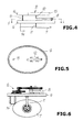
- the construction of the device 6 is to be seen from Figs. 4 to 8 .
- the device comprises a swingable fixed valve disk 7, which can be swivelled by use of a swing lever 8 into a closed position according to Fig. 2 or in an open position according to Fig. 3 .
- the closed position of the valve disk 7 the pipe 4 is closed with hermetical seal.
- the gas can flow through the pipe 4 without hindrance.
- the device 6 has according to Figs. 4 and 5 a plate-like support 9, the outer contour of which is adapted to the cross-section of the pipe 4.
- the support 9 is oval. It can have any other form of its contour, e. g. circular. That is true also for the valve disk 7 which is shown in Fig. 6 and 8 more detailed.
- the support 9 has at its peripheral area with advantage a sealing element all around.
- the wire-like swing lever 8 is fixed swingable. It can with advantage have the form of a "U", as to be seen from Fig. 4 , with two bended ends 10 and 11.
- the swing lever 8 is fastened to the support 9 with one of its thighs 12 of the U-like body and swingable around the axis of the same, as to be seen from Fig. 5 .
- the end 10 of the swing lever 8 projects into a cam disk 13 which is rotatable around its axis.
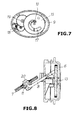
- the construction of the cam disk 13 is shown more detailed in Fig. 7 .
- the end 11 of the swing lever 8 projects into the valve disk 7.
- an electrical motor 14 which meshes with the cam disc 13 by a wheel 16 that is fastened to the end of its shaft 15.
- the cam disc 13 has curved track 17, into which the swing lever 8 projects with its end 10. This end 10 of the swing lever 8 is moved along the curved track 17 when the cam disk 13 is rotated.
- a gear unit comprising gear wheels 18 and 19, is positioned between the electrical motor 14 and the cam disk 13.
- the gear wheels 18 und 19 are fixes to the support 9 rotatable around their axis.
- the cam disk 13 has a gear rim at its peripheral area for meshing with the gear wheel 19.
- valve disk 7 When the "disturbance" which has caused the closing of the pipe 4, is removed the valve disk 7 can be opened by the electrical motor 14 with movement into the position of Fig. 3 under normal conditions with pressures e. g. up to 22 mbar.
- Such a ventilation valve can be with advantage a sealing element 20 which is mounted in the center of the valve disk 7 and which is moveable between two end positions in the direction of the middle axis of the valve disk 7.
- the swing lever 8 projects into the sealing element 20 with its end 11.
- the corresponding opening of the valve disk 7 is closed in its closed position hermetically sealing by the sealing element 20, because the swing lever 8 which is moved by the electrical motor 14 is pressed against or into the same.
- the pressure is removed, when the electrical motor 14 for the opening of the pipe 4 rotates in the opposite direction thereby lifting the swing valve 8 from the sealing element 20.
- the sealing element 20 then is moved into its second end position out of the valve disk 7 such that a slit-like opening occurs which allows for the desired pressure balance. As soon as the pressure difference is sufficient low, the electrical motor 14 can move the valve disk 7 into its open position.
- the sealing element 20 can have with advantage a hexagonal cross-section, to guarantee that it can not be rotated within the opening of the valve disk 7 having a corresponding internal cross-section. This also guarantees that the valve disk 7 can not rotate on the swing lever 8 relative to the same. That is necessary when e. g. the valve disk 7 has an oval form, according to the embodiments of the drawings.
Landscapes
- Engineering & Computer Science (AREA)
- General Engineering & Computer Science (AREA)
- Mechanical Engineering (AREA)
- Mechanically-Actuated Valves (AREA)
- Preventing Unauthorised Actuation Of Valves (AREA)
Abstract
Description
- The invention is concerned with an arrangement for the transport of a flowable pressurized medium, which comprises a pipe for guiding the medium and an adjusting mechanism with a valve disk and a drive, by which the valve disk can be moved into a locking position, in which the clear cross-section of the pipe is closed, and into an open position (
WO 2009/074431 A1 ). - Such an arrangement is known since long time. It can be used in principle for the transport of any flowable medium, which is liquid or gaseous. Of an essential value such an arrangement is for the transport of gas. This special use is discussed hereinafter - standing in also for other media. The arrangement inter alia is mounted, when the gas e. g. is used for heating purposes. The gas is delivered as a supporter of energy from the producer or supplier of the gas, a gas plant, or from a reservoir to users via pipes. Users can be e. g. companies, hospitals, other public institutions and private households. The consumption of gas and the depending remuneration which has to be paid to the supplier of the gas, is metered respectively with at least one gasmeter, that is installed at the user, which e. g. is connected to a gas pipe.
- It can happen that the flow route of the gas must be interrupted and opened again by an external action which can not be influenced by the user. Reasons for such an action can be that the user has not paid for the gas used by him or that a prepaid amount of money is used up or that manipulations are done at the gasmeter or the complete gas installation.
- From the
WO 2009/074431 A1 which is mentioned in the beginning, an arrangement is known, by use of which the flow route of gas within a pipe can be closed and opened again. The arrangement has a valve disk which fastened to the end of a shaft, which is positioned within the pipe and which can be moved by a drive that is connected to the shaft. In the closed position the valve disk closes an opening which is provided in the wall of the pipe, that is closed at its front face. The opening leads into a casing, by which the flow route of the gas is continued when the opening is not closed. This document is concerned in the main with additional elements of the valve disk or the adjusting mechanism, which are needed for a pressure relief, when the opening shall be opened again. All these elements also are positioned within the pipe. Thus the flow route of the gas is restricted by the valve disk and the corresponding adjusting mechanism. - It is the task of the invention, to improve the arrangement mentioned above such that the gas transporting pipe can be closed and opened in a simpler manner.
- According to the invention this task is solved by the features,
- that the valve disk is positioned at one end of a wire-like swing lever, which is fixed on a plate-like support in a swingable manner,
- that the other end of the swing lever is coupled to an electrical motor, which also is fastened to the support, and
- that the support in mounting position is connected with hermetically seal to the pipe such, that the valve disk projects into the same.
- This arrangement which comprises in the main the plate-like support and the swingable mounted valve disk can be installed into or to the pipe. The valve disk furthermore can be installed with the support such that it closes the pipe itself after action of the electrical motor. For this purpose it only is necessary to install the support, which carries the valve disk being mounted at the end of the swing lever, into the pipe or in an opening of the same which after mounting is sealed hermetically by the support. The flow route of the gas is not changed by the support and especially not restricted. Accordingly it is not necessary to provide an additional opening in the wall of the pipe which is to be closed and opened again by the valve disk which also needs a continuation of the flow route of the gas. As the valve disk during its operation makes a swinging movement it can be placed with advantage within the pipe such that it does not disturbed the flow of the gas but even supports the same with a corresponding sloping position, when the support of the valve disk is mounted at a position of the pipe, in which the same e.g. is bended about 90°.
- With special advantage the arrangement is installed within the housing of a gasmeter in a pipe which runs through the same. The dimensions of the support and the valve disk can be adapted easily to the dimensions of the pipe and be made especially very small. The dimensions of the housing of the gasmeter and of its components must no be changed.
- The swing lever in a preferred embodiment has the form of a "U" with its ends being bended to the side. It is fastened to the support in a swingable manner around the axis of one of its thighs.
- For the operation of the swing lever by the electrical motor one bended end of the same can project into a cam disk, which can rotate around its axis and is driven by the electrical motor and which has a curved track, in which the end of the swing lever slides, thereby effecting the swing movement of the valve disk.
- Between the electrical motor and the cam disk with advantage a gear unit comprising gear wheels can be mounted by which during operation of the electrical motor the cam disk is rotated around its axis. The cam disk for this purpose bears a gear rim at its peripheral area which meshes with the corresponding gear wheel of the gear unit. By this intermediately installed gear unit the pressure which is fed to the valve disk during the closing operation is increased essentially.
- The valve disk in principle can be moved back into its open position by the electrical motor. For this action pre-ventilation may be needed. For this purpose with advantage a sealing element can be installed in the center of the valve disk into which the swing lever projects with its one end. The sealing element is moveable between two end positions in the direction of the middle axis of the valve disk within the same. In one of the end positions the valve disk is sealed hermetically by the sealing element, while in its other endposition a slit-like opening is released. The sealing element preferably is protected against rotation within the valve disk.
- The electrical motor can be arranged in an electrical circuit with a switch which is actuated by a signal to switch of or turn out the electrical motor. The switch with advantage can be an electronically switch, e. g. a transistor. The signal for the electrical motor e. g. can be triggered, when a prepaid amount of money is consumed, when a corresponding order is given by a switchboard or when an unauthorized person manipulates the complete gas installation, especially the gasmeter. In the closed position of the valve disk the pipe is sealed hermetically. The gas then is blocked for the user. The valve disk in the closed position in addition is hold in this position by the pressure of the gas within the pipe.
- Preferred embodiments of the subject of the invention are shown in the drawings.
- The drawings show:
-
Fig. 1 schematically a part of a gas installation which is mounted at the building of a user. -
Fig. 2 the arrangement of the invention in its closed position, also schematically, in a very simple manner. -
Fig. 3 the arrangement analogues toFig. 2 in its open position. -
Fig. 4 a side view of the arrangement very schematically. -
Fig. 5 a cut throughFig. 4 along the line V-V. -
Fig. 6 a side view of the arrangement in a more detailed depiction. -
Fig. 7 a top view to a support of the arrangement on its side which is opposite to the valve disk. -
Fig. 8 the arrangement itself in its open position. - The arrangement of the invention can, as already mentioned, mounted into a gas pipe at any place in the area of a user. With advantage it is mounted within the housing of a gasmeter which is installed in a building of the user, because then only minor changes of the installation are needed and because at this place normally electrical current for the electrical motor is available. In the following this installation place is considered standing also for the other possible places.
-
Fig. 1 shows agasmeter 1 which e. g. is mounted in the building of a user. Gas is fed to the gasmeter through a supply-gas pipe 2. Aninternal gas pipe 3 starting from thegasmeter 1 is part of the internal pipe system of the user. It leads with corresponding distribution to different consumption places of gas. The supply-gas pipe 2 and theinternal gas pipe 3 are connected within the housing of thegas meter 1 by apipe 4 according toFigs. 2 and 3 . Thepipe 4 is - according to the shown embodiment - bended at its one end within the housing of thegasmeter 1 about an angle of 90°. A connectingpiece 5 which is formed by the bending protrudes from the housing of thegas meter 1. It serves for the connection of an extending pipe, e. g. theinternal gas pipe 3. - In the area of the bending of the pipe 4 a
device 6 for the closing and opening of the same is mounted within or at the same in a hermetically sealed manner. The construction of thedevice 6 is to be seen fromFigs. 4 to 8 . The device comprises a swingablefixed valve disk 7, which can be swivelled by use of aswing lever 8 into a closed position according toFig. 2 or in an open position according toFig. 3 . In the closed position of thevalve disk 7 thepipe 4 is closed with hermetical seal. In the open position the gas can flow through thepipe 4 without hindrance. - The
device 6 has according toFigs. 4 and 5 a plate-like support 9, the outer contour of which is adapted to the cross-section of thepipe 4. In the shown embodiment thesupport 9 is oval. It can have any other form of its contour, e. g. circular. That is true also for thevalve disk 7 which is shown inFig. 6 and8 more detailed. Thesupport 9 has at its peripheral area with advantage a sealing element all around. - On the
support 9 the wire-like swing lever 8 is fixed swingable. It can with advantage have the form of a "U", as to be seen fromFig. 4 , with two bended ends 10 and 11. Theswing lever 8 is fastened to thesupport 9 with one of itsthighs 12 of the U-like body and swingable around the axis of the same, as to be seen fromFig. 5 . Theend 10 of theswing lever 8 projects into acam disk 13 which is rotatable around its axis. The construction of thecam disk 13 is shown more detailed inFig. 7 . Theend 11 of theswing lever 8 projects into thevalve disk 7. - Also fastened to the
support 8 is anelectrical motor 14 which meshes with thecam disc 13 by awheel 16 that is fastened to the end of itsshaft 15. - The
cam disc 13 hascurved track 17, into which theswing lever 8 projects with itsend 10. Thisend 10 of theswing lever 8 is moved along thecurved track 17 when thecam disk 13 is rotated. - In a preferred embodiment a gear unit, comprising
gear wheels electrical motor 14 and thecam disk 13. Thegear wheels 18und 19 are fixes to thesupport 9 rotatable around their axis. Thecam disk 13 has a gear rim at its peripheral area for meshing with thegear wheel 19. By the gear unit the strength is increased which is fed to thevalve disk 7 by theswing lever 8 during the closing process. By the combination of gear unit andcurved track 17 of thecam disk 13, by which theswing lever 8 is guided, the pressure which is fed to thevalve disk 7 in its closed position is maintained with a self-locking effect even when theelectrical motor 14 does no longer presses against it with the end of theswing lever 8. The arrangement of the invention e. g. works as follows:
In case that the supply with gas for a user shall be interrupted, because e. g. the amount of a prepaid card is consumed or because of any other of the reasons mentioned above theelectrical motor 14 is activated, e. g. by a signal from an electronically circuit. Theelectrical motor 14 then rotates thecam disk 13 around its axis. By this movement theswing lever 8 also is moved along thecurved track 17 and swings thevalve disc 7 into its closed position according toFig. 2 . Thepipe 4 then is closed hermetically sealed such that gas can no more enter the internal pipes of the user. To improve the sealing a sealing element can be mounted to the peripheral area of thevalve disk 7, preferably a sealing strip. - When the "disturbance" which has caused the closing of the
pipe 4, is removed thevalve disk 7 can be opened by theelectrical motor 14 with movement into the position ofFig. 3 under normal conditions with pressures e. g. up to 22 mbar. - But in case of a disturbance at a pre mounted upstream control valve also pressures between e. g. 150 mbar and 300 mbar can occur within the supply-
gas pipe 2, which acts on thevalve disk 7 such that for an opening of the same a pre-ventilation is needed. Such a pre-ventilation, by which the pressure difference on the two opposing sides of thevalve disk 7 can be decreased such that thevalve disk 7 can be opened by theelectrical motor 14, can be e. g. a ventilation valve which is mounted to thevalve disc 7. - Such a ventilation valve can be with advantage a sealing
element 20 which is mounted in the center of thevalve disk 7 and which is moveable between two end positions in the direction of the middle axis of thevalve disk 7. Theswing lever 8 projects into the sealingelement 20 with itsend 11. The corresponding opening of thevalve disk 7 is closed in its closed position hermetically sealing by the sealingelement 20, because theswing lever 8 which is moved by theelectrical motor 14 is pressed against or into the same. The pressure is removed, when theelectrical motor 14 for the opening of thepipe 4 rotates in the opposite direction thereby lifting theswing valve 8 from the sealingelement 20. The sealingelement 20 then is moved into its second end position out of thevalve disk 7 such that a slit-like opening occurs which allows for the desired pressure balance. As soon as the pressure difference is sufficient low, theelectrical motor 14 can move thevalve disk 7 into its open position. - The sealing
element 20 can have with advantage a hexagonal cross-section, to guarantee that it can not be rotated within the opening of thevalve disk 7 having a corresponding internal cross-section. This also guarantees that thevalve disk 7 can not rotate on theswing lever 8 relative to the same. That is necessary when e. g. thevalve disk 7 has an oval form, according to the embodiments of the drawings.
Claims (7)
- Arrangement for the transport of a flowable pressurized medium, which comprises a pipe for guiding the medium and an adjusting mechanism with a valve disk and a drive, by which the valve disk can be moved into a locking position, in which the clear cross-section of the pipe is closed, and into an open position, characterized in- that the valve disk (7) is positioned at one end of a wire-like swing lever (8), which is fixed on a plate-like support (9) in a swingable manner,- that the other end of the swing lever (8) is coupled to an electrical motor (14), which also is fastened to the support (9), and- that the support (9) in mounting position is connected with hermetically seal to the pipe (4) such, that the valve disk (7) projects into the same.
- Arrangement according to claim 1, characterized in that the swing lever (8) is bended into a U-form and fixed to the support (9) with one of its thighs (12), around the axis of which the swing lever (8) is swingable.
- Arrangement according to claim 1 or 2, characterized in that the electrical motor (14) is coupled with a cam disk (13) being rotatable around its axis by the electrical motor (14) and having a curved track (17) into which the swing lever (8) projects with one of its ends.
- Arrangement according to claim 3, characterized in that a gear unit comprising gear wheels (18,19) is positioned between the electrical motor (14) and the cam disk (13) which bears a gear rim at its peripheral area.
- Arrangement according to one of the claims 1 to 4, characterized in that the valve disk (7) has a sealing element at its peripheral area, preferably a sealing strip.
- Arrangement according to one of the claims 1 to 5, characterized in- that a sealing element (20) is positioned in the center of the valve disk (7) and is moveable between two endpositions in the direction of the middle axis of the valve disk (7), into which the swing lever (8) penetrates with its corresponding end, and- that in one of the endpositions of the sealing element (20) the valve disk (7) is closed hermetically sealed, while in the other endposition of the same a slit- like throughhole is realized.
- Arrangement according to claim 6, characterized in that the sealing element (20) is protected within the valve disk (7) against rotation around the middle axis of the same.
Priority Applications (4)
| Application Number | Priority Date | Filing Date | Title |
|---|---|---|---|
| EP20100191354 EP2453154B1 (en) | 2010-11-16 | 2010-11-16 | Arrangement for the transmission of a flowable medium |
| ES10191354T ES2441618T3 (en) | 2010-11-16 | 2010-11-16 | Mounting for the transmission of a fluid medium |
| ARP110104256 AR084727A1 (en) | 2010-11-16 | 2011-11-14 | PROVISION FOR TRANSMISSION OF A FLUID HALF |
| BRPI1105666-5A BRPI1105666A2 (en) | 2010-11-16 | 2011-11-16 | Arrangement for the transmission of a medium |
Applications Claiming Priority (1)
| Application Number | Priority Date | Filing Date | Title |
|---|---|---|---|
| EP20100191354 EP2453154B1 (en) | 2010-11-16 | 2010-11-16 | Arrangement for the transmission of a flowable medium |
Publications (2)
| Publication Number | Publication Date |
|---|---|
| EP2453154A1 true EP2453154A1 (en) | 2012-05-16 |
| EP2453154B1 EP2453154B1 (en) | 2013-11-13 |
Family
ID=43858062
Family Applications (1)
| Application Number | Title | Priority Date | Filing Date |
|---|---|---|---|
| EP20100191354 Active EP2453154B1 (en) | 2010-11-16 | 2010-11-16 | Arrangement for the transmission of a flowable medium |
Country Status (4)
| Country | Link |
|---|---|
| EP (1) | EP2453154B1 (en) |
| AR (1) | AR084727A1 (en) |
| BR (1) | BRPI1105666A2 (en) |
| ES (1) | ES2441618T3 (en) |
Citations (4)
| Publication number | Priority date | Publication date | Assignee | Title |
|---|---|---|---|---|
| GB856212A (en) * | 1958-02-22 | 1960-12-14 | Welf Folkmar Gerdts | Improvements in or relating to manually-operable flap valves |
| EP0680839A1 (en) * | 1994-05-03 | 1995-11-08 | VALEO GmbH Klimasysteme | Device for actuating of a flap |
| EP0780607A1 (en) * | 1995-12-19 | 1997-06-25 | Valeo Climatisation | Butterfly valve actuator for a motor vehicle heating and/or air-conditioning installation |
| WO2009074431A1 (en) | 2007-12-11 | 2009-06-18 | Elster Gmbh | Device for blocking and releasing a fluid flow and associated method |
-
2010
- 2010-11-16 ES ES10191354T patent/ES2441618T3/en active Active
- 2010-11-16 EP EP20100191354 patent/EP2453154B1/en active Active
-
2011
- 2011-11-14 AR ARP110104256 patent/AR084727A1/en unknown
- 2011-11-16 BR BRPI1105666-5A patent/BRPI1105666A2/en not_active IP Right Cessation
Patent Citations (4)
| Publication number | Priority date | Publication date | Assignee | Title |
|---|---|---|---|---|
| GB856212A (en) * | 1958-02-22 | 1960-12-14 | Welf Folkmar Gerdts | Improvements in or relating to manually-operable flap valves |
| EP0680839A1 (en) * | 1994-05-03 | 1995-11-08 | VALEO GmbH Klimasysteme | Device for actuating of a flap |
| EP0780607A1 (en) * | 1995-12-19 | 1997-06-25 | Valeo Climatisation | Butterfly valve actuator for a motor vehicle heating and/or air-conditioning installation |
| WO2009074431A1 (en) | 2007-12-11 | 2009-06-18 | Elster Gmbh | Device for blocking and releasing a fluid flow and associated method |
Also Published As
| Publication number | Publication date |
|---|---|
| EP2453154B1 (en) | 2013-11-13 |
| AR084727A1 (en) | 2013-06-05 |
| BRPI1105666A2 (en) | 2015-07-28 |
| ES2441618T3 (en) | 2014-02-05 |
Similar Documents
| Publication | Publication Date | Title |
|---|---|---|
| US9410636B2 (en) | Flow control/shut-off valve assembly | |
| US20020175226A1 (en) | Emergency eyewash apparatus | |
| RU2473829C2 (en) | Device to shut off and open fluid flow and appropriate method | |
| WO2008016698A3 (en) | Fluid flow regulating device | |
| MXPA01010626A (en) | Device for controlling flowing media. | |
| BRPI0703269A (en) | closed loop fluid delivery system | |
| WO2008033241A2 (en) | Slow closing actuator and valve | |
| CN103403417B (en) | Integration has with the ball valve of cam-operated built-in microswitch | |
| EP2453154B1 (en) | Arrangement for the transmission of a flowable medium | |
| US3473695A (en) | Liquid metering valve unit | |
| JP2008224647A (en) | Back-flow prevention component of water meter | |
| GB9907832D0 (en) | A tap | |
| GB0018911D0 (en) | Automatic valves | |
| US5035195A (en) | Valve shut-off flag | |
| JP2532140Y2 (en) | Repair valve | |
| KR101699224B1 (en) | Indication Device For Opening and Closing Appearance of Valve | |
| US268733A (en) | Bebman | |
| KR200458726Y1 (en) | Tamper switch structure of butterfly valve | |
| US4522225A (en) | Cock for the heating circuits of a vehicle | |
| CN216112217U (en) | Intelligent adjusting butterfly valve | |
| WO2015184213A1 (en) | Flow control/shut-off valve assembly | |
| US20070064518A1 (en) | System and method for controlling the release of pressurized fluid for concrete mixing | |
| US926963A (en) | Key-receptacle. | |
| CN113175545B (en) | Flow-adjustable three-way electromagnetic valve | |
| JP4426705B2 (en) | Valve body open / close display device |
Legal Events
| Date | Code | Title | Description |
|---|---|---|---|
| PUAI | Public reference made under article 153(3) epc to a published international application that has entered the european phase |
Free format text: ORIGINAL CODE: 0009012 |
|
| AK | Designated contracting states |
Kind code of ref document: A1 Designated state(s): AL AT BE BG CH CY CZ DE DK EE ES FI FR GB GR HR HU IE IS IT LI LT LU LV MC MK MT NL NO PL PT RO RS SE SI SK SM TR |
|
| AX | Request for extension of the european patent |
Extension state: BA ME |
|
| 17P | Request for examination filed |
Effective date: 20121114 |
|
| GRAP | Despatch of communication of intention to grant a patent |
Free format text: ORIGINAL CODE: EPIDOSNIGR1 |
|
| GRAS | Grant fee paid |
Free format text: ORIGINAL CODE: EPIDOSNIGR3 |
|
| GRAA | (expected) grant |
Free format text: ORIGINAL CODE: 0009210 |
|
| AK | Designated contracting states |
Kind code of ref document: B1 Designated state(s): AL AT BE BG CH CY CZ DE DK EE ES FI FR GB GR HR HU IE IS IT LI LT LU LV MC MK MT NL NO PL PT RO RS SE SI SK SM TR |
|
| REG | Reference to a national code |
Ref country code: GB Ref legal event code: FG4D |
|
| REG | Reference to a national code |
Ref country code: CH Ref legal event code: EP |
|
| REG | Reference to a national code |
Ref country code: AT Ref legal event code: REF Ref document number: 640722 Country of ref document: AT Kind code of ref document: T Effective date: 20131215 |
|
| REG | Reference to a national code |
Ref country code: IE Ref legal event code: FG4D |
|
| REG | Reference to a national code |
Ref country code: DE Ref legal event code: R096 Ref document number: 602010011689 Country of ref document: DE Effective date: 20140109 |
|
| REG | Reference to a national code |
Ref country code: ES Ref legal event code: FG2A Ref document number: 2441618 Country of ref document: ES Kind code of ref document: T3 Effective date: 20140205 |
|
| REG | Reference to a national code |
Ref country code: NL Ref legal event code: VDEP Effective date: 20131113 |
|
| REG | Reference to a national code |
Ref country code: AT Ref legal event code: MK05 Ref document number: 640722 Country of ref document: AT Kind code of ref document: T Effective date: 20131113 |
|
| REG | Reference to a national code |
Ref country code: LT Ref legal event code: MG4D |
|
| PG25 | Lapsed in a contracting state [announced via postgrant information from national office to epo] |
Ref country code: FI Free format text: LAPSE BECAUSE OF FAILURE TO SUBMIT A TRANSLATION OF THE DESCRIPTION OR TO PAY THE FEE WITHIN THE PRESCRIBED TIME-LIMIT Effective date: 20131113 Ref country code: IS Free format text: LAPSE BECAUSE OF FAILURE TO SUBMIT A TRANSLATION OF THE DESCRIPTION OR TO PAY THE FEE WITHIN THE PRESCRIBED TIME-LIMIT Effective date: 20140313 Ref country code: NL Free format text: LAPSE BECAUSE OF FAILURE TO SUBMIT A TRANSLATION OF THE DESCRIPTION OR TO PAY THE FEE WITHIN THE PRESCRIBED TIME-LIMIT Effective date: 20131113 Ref country code: HR Free format text: LAPSE BECAUSE OF FAILURE TO SUBMIT A TRANSLATION OF THE DESCRIPTION OR TO PAY THE FEE WITHIN THE PRESCRIBED TIME-LIMIT Effective date: 20131113 Ref country code: NO Free format text: LAPSE BECAUSE OF FAILURE TO SUBMIT A TRANSLATION OF THE DESCRIPTION OR TO PAY THE FEE WITHIN THE PRESCRIBED TIME-LIMIT Effective date: 20140213 Ref country code: LT Free format text: LAPSE BECAUSE OF FAILURE TO SUBMIT A TRANSLATION OF THE DESCRIPTION OR TO PAY THE FEE WITHIN THE PRESCRIBED TIME-LIMIT Effective date: 20131113 Ref country code: SE Free format text: LAPSE BECAUSE OF FAILURE TO SUBMIT A TRANSLATION OF THE DESCRIPTION OR TO PAY THE FEE WITHIN THE PRESCRIBED TIME-LIMIT Effective date: 20131113 |
|
| PG25 | Lapsed in a contracting state [announced via postgrant information from national office to epo] |
Ref country code: LV Free format text: LAPSE BECAUSE OF FAILURE TO SUBMIT A TRANSLATION OF THE DESCRIPTION OR TO PAY THE FEE WITHIN THE PRESCRIBED TIME-LIMIT Effective date: 20131113 Ref country code: RS Free format text: LAPSE BECAUSE OF FAILURE TO SUBMIT A TRANSLATION OF THE DESCRIPTION OR TO PAY THE FEE WITHIN THE PRESCRIBED TIME-LIMIT Effective date: 20131113 Ref country code: BE Free format text: LAPSE BECAUSE OF FAILURE TO SUBMIT A TRANSLATION OF THE DESCRIPTION OR TO PAY THE FEE WITHIN THE PRESCRIBED TIME-LIMIT Effective date: 20131113 Ref country code: CY Free format text: LAPSE BECAUSE OF FAILURE TO SUBMIT A TRANSLATION OF THE DESCRIPTION OR TO PAY THE FEE WITHIN THE PRESCRIBED TIME-LIMIT Effective date: 20131113 Ref country code: AT Free format text: LAPSE BECAUSE OF FAILURE TO SUBMIT A TRANSLATION OF THE DESCRIPTION OR TO PAY THE FEE WITHIN THE PRESCRIBED TIME-LIMIT Effective date: 20131113 |
|
| PG25 | Lapsed in a contracting state [announced via postgrant information from national office to epo] |
Ref country code: PT Free format text: LAPSE BECAUSE OF FAILURE TO SUBMIT A TRANSLATION OF THE DESCRIPTION OR TO PAY THE FEE WITHIN THE PRESCRIBED TIME-LIMIT Effective date: 20140313 |
|
| PG25 | Lapsed in a contracting state [announced via postgrant information from national office to epo] |
Ref country code: EE Free format text: LAPSE BECAUSE OF FAILURE TO SUBMIT A TRANSLATION OF THE DESCRIPTION OR TO PAY THE FEE WITHIN THE PRESCRIBED TIME-LIMIT Effective date: 20131113 |
|
| REG | Reference to a national code |
Ref country code: DE Ref legal event code: R097 Ref document number: 602010011689 Country of ref document: DE |
|
| REG | Reference to a national code |
Ref country code: IE Ref legal event code: MM4A |
|
| PG25 | Lapsed in a contracting state [announced via postgrant information from national office to epo] |
Ref country code: RO Free format text: LAPSE BECAUSE OF FAILURE TO SUBMIT A TRANSLATION OF THE DESCRIPTION OR TO PAY THE FEE WITHIN THE PRESCRIBED TIME-LIMIT Effective date: 20131113 Ref country code: CZ Free format text: LAPSE BECAUSE OF FAILURE TO SUBMIT A TRANSLATION OF THE DESCRIPTION OR TO PAY THE FEE WITHIN THE PRESCRIBED TIME-LIMIT Effective date: 20131113 Ref country code: PL Free format text: LAPSE BECAUSE OF FAILURE TO SUBMIT A TRANSLATION OF THE DESCRIPTION OR TO PAY THE FEE WITHIN THE PRESCRIBED TIME-LIMIT Effective date: 20131113 Ref country code: SK Free format text: LAPSE BECAUSE OF FAILURE TO SUBMIT A TRANSLATION OF THE DESCRIPTION OR TO PAY THE FEE WITHIN THE PRESCRIBED TIME-LIMIT Effective date: 20131113 |
|
| PLBE | No opposition filed within time limit |
Free format text: ORIGINAL CODE: 0009261 |
|
| STAA | Information on the status of an ep patent application or granted ep patent |
Free format text: STATUS: NO OPPOSITION FILED WITHIN TIME LIMIT |
|
| PG25 | Lapsed in a contracting state [announced via postgrant information from national office to epo] |
Ref country code: DK Free format text: LAPSE BECAUSE OF FAILURE TO SUBMIT A TRANSLATION OF THE DESCRIPTION OR TO PAY THE FEE WITHIN THE PRESCRIBED TIME-LIMIT Effective date: 20131113 |
|
| 26N | No opposition filed |
Effective date: 20140814 |
|
| PG25 | Lapsed in a contracting state [announced via postgrant information from national office to epo] |
Ref country code: IE Free format text: LAPSE BECAUSE OF NON-PAYMENT OF DUE FEES Effective date: 20131116 |
|
| REG | Reference to a national code |
Ref country code: DE Ref legal event code: R097 Ref document number: 602010011689 Country of ref document: DE Effective date: 20140814 |
|
| PG25 | Lapsed in a contracting state [announced via postgrant information from national office to epo] |
Ref country code: SI Free format text: LAPSE BECAUSE OF FAILURE TO SUBMIT A TRANSLATION OF THE DESCRIPTION OR TO PAY THE FEE WITHIN THE PRESCRIBED TIME-LIMIT Effective date: 20131113 |
|
| PG25 | Lapsed in a contracting state [announced via postgrant information from national office to epo] |
Ref country code: MC Free format text: LAPSE BECAUSE OF FAILURE TO SUBMIT A TRANSLATION OF THE DESCRIPTION OR TO PAY THE FEE WITHIN THE PRESCRIBED TIME-LIMIT Effective date: 20131113 |
|
| PG25 | Lapsed in a contracting state [announced via postgrant information from national office to epo] |
Ref country code: SM Free format text: LAPSE BECAUSE OF FAILURE TO SUBMIT A TRANSLATION OF THE DESCRIPTION OR TO PAY THE FEE WITHIN THE PRESCRIBED TIME-LIMIT Effective date: 20131113 |
|
| PG25 | Lapsed in a contracting state [announced via postgrant information from national office to epo] |
Ref country code: TR Free format text: LAPSE BECAUSE OF FAILURE TO SUBMIT A TRANSLATION OF THE DESCRIPTION OR TO PAY THE FEE WITHIN THE PRESCRIBED TIME-LIMIT Effective date: 20131113 |
|
| REG | Reference to a national code |
Ref country code: CH Ref legal event code: PL |
|
| PG25 | Lapsed in a contracting state [announced via postgrant information from national office to epo] |
Ref country code: CH Free format text: LAPSE BECAUSE OF NON-PAYMENT OF DUE FEES Effective date: 20141130 Ref country code: BG Free format text: LAPSE BECAUSE OF FAILURE TO SUBMIT A TRANSLATION OF THE DESCRIPTION OR TO PAY THE FEE WITHIN THE PRESCRIBED TIME-LIMIT Effective date: 20131113 Ref country code: MK Free format text: LAPSE BECAUSE OF FAILURE TO SUBMIT A TRANSLATION OF THE DESCRIPTION OR TO PAY THE FEE WITHIN THE PRESCRIBED TIME-LIMIT Effective date: 20131113 Ref country code: HU Free format text: LAPSE BECAUSE OF FAILURE TO SUBMIT A TRANSLATION OF THE DESCRIPTION OR TO PAY THE FEE WITHIN THE PRESCRIBED TIME-LIMIT; INVALID AB INITIO Effective date: 20101116 Ref country code: LU Free format text: LAPSE BECAUSE OF NON-PAYMENT OF DUE FEES Effective date: 20131116 Ref country code: LI Free format text: LAPSE BECAUSE OF NON-PAYMENT OF DUE FEES Effective date: 20141130 |
|
| PG25 | Lapsed in a contracting state [announced via postgrant information from national office to epo] |
Ref country code: GR Free format text: LAPSE BECAUSE OF NON-PAYMENT OF DUE FEES Effective date: 20131113 Ref country code: MT Free format text: LAPSE BECAUSE OF FAILURE TO SUBMIT A TRANSLATION OF THE DESCRIPTION OR TO PAY THE FEE WITHIN THE PRESCRIBED TIME-LIMIT Effective date: 20131113 |
|
| REG | Reference to a national code |
Ref country code: FR Ref legal event code: PLFP Year of fee payment: 6 |
|
| PG25 | Lapsed in a contracting state [announced via postgrant information from national office to epo] |
Ref country code: GR Free format text: LAPSE BECAUSE OF FAILURE TO SUBMIT A TRANSLATION OF THE DESCRIPTION OR TO PAY THE FEE WITHIN THE PRESCRIBED TIME-LIMIT Effective date: 20140214 |
|
| REG | Reference to a national code |
Ref country code: FR Ref legal event code: PLFP Year of fee payment: 7 |
|
| REG | Reference to a national code |
Ref country code: FR Ref legal event code: PLFP Year of fee payment: 8 |
|
| REG | Reference to a national code |
Ref country code: FR Ref legal event code: PLFP Year of fee payment: 9 |
|
| PG25 | Lapsed in a contracting state [announced via postgrant information from national office to epo] |
Ref country code: AL Free format text: LAPSE BECAUSE OF FAILURE TO SUBMIT A TRANSLATION OF THE DESCRIPTION OR TO PAY THE FEE WITHIN THE PRESCRIBED TIME-LIMIT Effective date: 20131113 |
|
| P01 | Opt-out of the competence of the unified patent court (upc) registered |
Effective date: 20230519 |
|
| PGFP | Annual fee paid to national office [announced via postgrant information from national office to epo] |
Ref country code: GB Payment date: 20250925 Year of fee payment: 16 |
|
| PGFP | Annual fee paid to national office [announced via postgrant information from national office to epo] |
Ref country code: FR Payment date: 20250908 Year of fee payment: 16 |
|
| PGFP | Annual fee paid to national office [announced via postgrant information from national office to epo] |
Ref country code: DE Payment date: 20250923 Year of fee payment: 16 |
|
| PGFP | Annual fee paid to national office [announced via postgrant information from national office to epo] |
Ref country code: IT Payment date: 20251022 Year of fee payment: 16 |
|
| PGFP | Annual fee paid to national office [announced via postgrant information from national office to epo] |
Ref country code: ES Payment date: 20251210 Year of fee payment: 16 |