EP2453127A1 - Heat engine regenerator and stirling engine using the regenerator - Google Patents
Heat engine regenerator and stirling engine using the regenerator Download PDFInfo
- Publication number
- EP2453127A1 EP2453127A1 EP10796914A EP10796914A EP2453127A1 EP 2453127 A1 EP2453127 A1 EP 2453127A1 EP 10796914 A EP10796914 A EP 10796914A EP 10796914 A EP10796914 A EP 10796914A EP 2453127 A1 EP2453127 A1 EP 2453127A1
- Authority
- EP
- European Patent Office
- Prior art keywords
- regenerator
- layered
- heat engine
- degrees
- meshes
- Prior art date
- Legal status (The legal status is an assumption and is not a legal conclusion. Google has not performed a legal analysis and makes no representation as to the accuracy of the status listed.)
- Withdrawn
Links
Images



Classifications
-
- F—MECHANICAL ENGINEERING; LIGHTING; HEATING; WEAPONS; BLASTING
- F02—COMBUSTION ENGINES; HOT-GAS OR COMBUSTION-PRODUCT ENGINE PLANTS
- F02G—HOT GAS OR COMBUSTION-PRODUCT POSITIVE-DISPLACEMENT ENGINE PLANTS; USE OF WASTE HEAT OF COMBUSTION ENGINES; NOT OTHERWISE PROVIDED FOR
- F02G1/00—Hot gas positive-displacement engine plants
- F02G1/04—Hot gas positive-displacement engine plants of closed-cycle type
- F02G1/043—Hot gas positive-displacement engine plants of closed-cycle type the engine being operated by expansion and contraction of a mass of working gas which is heated and cooled in one of a plurality of constantly communicating expansible chambers, e.g. Stirling cycle type engines
- F02G1/053—Component parts or details
- F02G1/057—Regenerators
-
- F—MECHANICAL ENGINEERING; LIGHTING; HEATING; WEAPONS; BLASTING
- F24—HEATING; RANGES; VENTILATING
- F24H—FLUID HEATERS, e.g. WATER OR AIR HEATERS, HAVING HEAT-GENERATING MEANS, e.g. HEAT PUMPS, IN GENERAL
- F24H2240/00—Fluid heaters having electrical generators
- F24H2240/12—Fluid heaters having electrical generators with thermodynamic cycle for converting thermal energy to mechanical power to produce electrical energy
- F24H2240/122—Stirling cycles
Definitions
- the present invention relates to a heat engine regenerator and a Stirling engine using the regenerator. More particularly, the present invention relates to a regenerator that is used in a heat engine such as a Stirling engine in order to provide and receive enthalpy to and from a working fluid, and relates to a Stirling engine using the regenerator.
- regenerators are used as heat exchangers in, for example, Stirling engines and boilers for thermal power generation.
- Such a regenerator receives a part of enthalpy of a high-temperature fluid from the high-temperature fluid and stores the received enthalpy, and provides part of the stored enthalpy to a low-temperature fluid.
- Patent Literature 1 discloses a so-called ⁇ -type (single cylinder/displacer type) Stirling engine, which is one example of the aforementioned Stirling engine.
- a ⁇ -type Stirling engine includes: a piston for use in varying a volume ratio between a high-temperature side work space (hereinafter, referred to as an expansion space) and a low-temperature side work space (hereinafter, referred to as a compression space) within a single cylinder (hereinafter, this piston is referred to as a displacer); and a piston for use in varying the volume of the entire work space (hereinafter, this piston is referred to as an output piston or a power piston).
- a fluid passage through which the expansion space and the compression space communicate with each other is formed around the outer periphery of the cylinder.
- An upper part of the fluid passage is a part of a heating section which includes heating means, and a lower part of the fluid passage is a part of a cooling section which includes cooling means.
- a regenerator is provided between the heating section and the cooling section.
- the regenerator is in a cylindrical shape and has space formed at its center.
- the cylinder is disposed in the space. This type of regenerator is called an annular regenerator.
- a working fluid such as helium moves between the expansion space and the compression space through the heating section, the regenerator, and the cooling section in a reciprocating manner.
- the regenerator receives enthalpy from a high-temperature fluid, i.e., the working fluid that has passed through the heating section and of which the temperature has been increased, and stores the received enthalpy.
- the regenerator radiates heat and provides the heat to a low-temperature fluid, i.e., the working fluid that has passed through the cooling section and of which the temperature has been reduced.
- the displacer and the power piston move in a reciprocating manner with a constant phase difference therebetween.
- Power is extracted via separate drive rods (output rods), which are a drive rode connected to the displacer and a drive rod connected to the power piston.
- regenerators are employable. Due to functions required for regenerators, a metallic porous body that is excellent in terms of air permeability and thermal conductivity is often used in a regenerator. In particular, a large number of layered metallic meshes are used. Such layered metallic meshes are used also in the regenerator of the Stirling engine disclosed in Patent Literature 1.
- Each metallic mesh is formed of a large number of mutually parallel longitudinal strands and a large number of mutually parallel lateral strands perpendicular to the longitudinal strands. In both the longitudinal strands and the lateral strands, each strand is spaced apart from the other with a substantially consistent pitch.
- Patent Literature 2 Patent Literature 3
- Patent Literature 4 Patent Literature 4
- Patent Literature 3 Patent Literature 4
- Patent Literature 4 disclose specific rules, general practice, and past records that refer to unifying a mesh strand direction among multiple metallic meshes.
- An object of the present invention is to provide a heat engine regenerator with improved performance that is realized even with use of conventional publicly known metallic meshes and with no necessity of adding other components to the regenerator, and to provide a Stirling engine using the regenerator.
- a heat engine regenerator for use in a heat engine is configured to receive and store heat from a high-temperature gas flowing from a high-temperature space into the heat engine regenerator, and to provide the heat to a low-temperature fluid flowing from a low-temperature space into the heat engine regenerator.
- the heat engine regenerator includes a large number of layered metallic meshes. Each metallic mesh includes a large number of mutually parallel longitudinal strands and a large number of mutually parallel lateral strands perpendicular to the longitudinal strands.
- the metallic meshes are layered such that each metallic mesh is sequentially rotated in a same direction by a fixed angle with respect to an immediately previously layered metal mesh.
- a fluid passage including complex paths is formed in a manner to extend through a metallic mesh layered body.
- each metallic mesh is preferably round-shaped or annular-shaped.
- the metallic meshes are layered such that the longitudinal strands of adjacent metallic meshes that are arranged one above another cross each other and the lateral strands of the adjacent metallic meshes that are arranged one above another cross each other.
- the angle may be selected in a range from 10 to 80 degrees.
- the angle may be selected in a range from 30 to 60 degrees.
- the angle may be one of 30 degrees, 45 degrees, and 60 degrees.
- a Stirling engine includes: an expansion space for a working fluid; a compression space for the working fluid; pistons with which the expansion space and the compression space are demarcated; and a regenerator provided in a fluid passage through which the expansion space and the compression space communicate with each other.
- the regenerator is one of the above-described heat engine regenerators.
- the Stirling engine includes a regenerator according to the present invention as described above, a reduction in fluid frictional coefficient is realized, which is an excellent operational advantage of the present invention. As a result, engine efficiency of the Stirling engine is improved.
- the heat engine regenerator of the present invention a passage resistance against a working fluid is reduced even with use of a conventional publicly known metallic mesh material and with no necessity of adding other components to the regenerator. As a result, regeneration efficiency of the heat engine regenerator is improved. Consequently, engine efficiency of a heat engine using the regenerator is improved.
- a Stirling engine 1 shown in Fig. 1 is a so-called ⁇ -type Stirling engine, which is similar to the one described in Background Art.
- the Stirling engine 1 includes an expansion space 4 which is formed in an upper part of a single cylinder 2 by being partitioned off with a slidable displacer 3, and a compression space 6 which is formed in a lower part of the single cylinder 2 by being demarcated with the displacer 3 and a power piston 5.
- a displacer rod 3a is attached to the displacer 3 in a manner to extend through the power piston 5.
- Output rods 5a are attached to the power piston 5.
- the output rods 5a are unique to the power piston 5.
- the displacer rod 3a and the output rods 5a are connected to, for example, a crank shaft (not shown).
- the displacer 3 and the power piston 5 move in a reciprocating manner with a constant phase difference therebetween.
- the crank shaft connected to the displacer rod 3a and the output rods 5a is rotated.
- a pipe 8, through which the expansion space 4 communicates with the chamber 7, is provided at the top end of the cylinder 2.
- a heater 9a for use in heating a working fluid such as helium within the pipe 8 is disposed at a position in proximity to the pipe 8.
- the pipe 8 and the heater 9a form a heating section 9.
- An upper internal part of the chamber 7 is filled with a layered body 110 of metallic meshes (hereinafter, referred to as "metal meshes") 11, which is a filling component of a regenerator 10.
- the regenerator 10 is an annular regenerator having hollow space 10a (see Fig. 2 ) at its center.
- the cylinder 2 is disposed in the hollow space 10a.
- a cooling section 12 is formed below the regenerator 10.
- a cooling liquid 12a circulates within the cooling section 12.
- the cooling section 12 communicates with the compression space 6.
- the compression space 6 When the displacer 3 descends, the compression space 6 is compressed, accordingly. As a result, a low-temperature working fluid within the compression space 6 flows through the cooling section 12. Then, the working fluid receives heat at the regenerator 10 and thereby the temperature of the working fluid is increased. Thereafter, the working fluid is further heated up at the heating section 9. The working fluid, which is thus heated up and thereby expanded, is sent into the expansion space 4.
- the displacer 3 ascends after reaching the bottom dead center.
- the high-temperature working fluid within the expansion space 4 flows through the heating section 9 and reaches the regenerator 10 where the layered body 110 of the metal meshes 11 receives enthalpy from the high-temperature working fluid and stores the received enthalpy. In this manner, the working fluid is cooled down at the regenerator 10. The working fluid is further cooled down at the cooling section, and then flows into the compression space 6.
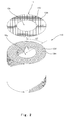
- Fig. 2 shows the layered body 110 of annular metal meshes 11, which is a filling component of the regenerator 10.
- the metal meshes 11 may be formed in a round shape.
- Each metal mesh 11 is formed of a large number of mutually parallel longitudinal strands 13V and a large number of mutually parallel lateral strands 13H perpendicular to the longitudinal strands 13V.
- each strand is spaced apart from the other with a substantially consistent pitch. Accordingly, the longitudinal strands 13V and the lateral strands 13H form square openings 14.
- Each metal mesh 11 is formed by plain weaving the strands, each of which has an external diameter dm of approximately 0.05 to 0.2 mm, with a pitch Pt which is approximately 2.5 times greater than the strand diameter. It should be understood that the pitch dimension is not limited to this.
- the metal meshes 11 are layered in the following manner: with respect to a strand direction of a metal mesh 11 that is first placed for the mesh layering, the other metal meshes 11 to be layered thereon are rotated such that each metal mesh is sequentially rotated in the same direction by a fixed angle with respect to an immediately previously layered metal mesh 11.
- first and second metal meshes are layered with reference to the longitudinal strands of the first metal mesh in the following manner: the second metal mesh is layered on the first metal mesh such that the direction of the longitudinal strands of the second metal mesh is rotated by 45 degrees from the direction of the longitudinal strands of the first metal mesh.
- the third metal mesh is layered on the second metal mesh such that the third metal mesh is also rotated in the same rotational direction by 45 degrees with respect to the longitudinal strands of the second metal mesh.
- the rotation angle is not limited to 45 degrees but may be, for example, 30 degrees, 60 degrees, or another angle.
- the present embodiment does not include 90 degrees as the rotation angle, because the longitudinal strands 13V and the lateral strands 13H are perpendicular to each other and making a 90-degree rotation is substantially the same as no rotation being made.
- Figs. 4A, 4B, and 4C show the same portion of respective metal meshes 11 that are layered such that each metal mesh 11 is sequentially rotated in the same direction by 30 degrees with respect to an immediately previously layered metal mesh 11.
- Fig. 4A is a 3n-2th (e.g., first) metal mesh 11;
- Fig. 4 B is a 3n-1th (e.g., second) metal mesh 11;
- Fig. 4 C is a 3nth (e.g., third) metal mesh.
- n is a positive integer, the minimum value of which is 1.
- the metal meshes 11 are layered with respective strand directions as shown in Figs. 4A, 4B, and 4C .
- a layered body in which each metal mesh 11 is sequentially rotated in the same direction by 30 degrees with respect to an immediately previously layered metal mesh 11 appears to be the same as a layered body in which each metal mesh 11 is sequentially rotated in the same direction by 60 degrees with respect to an immediately previously layered metal mesh 11.
- a manner in which the strands 13V and 13H are layered and a manner in which the openings 14 overlap one above another are different between these two cases when seen three dimensionally. The same is true in the case of comparing, for example, a 15-degree rotation and a 75-degree rotation.
- a layered body with the rotation of ⁇ degrees, and a layered body with the rotation of (90- ⁇ ) degrees are different in terms of the shape of a working fluid passage.
- the passage is formed mainly from the openings 14 of a large number of metal meshes, the openings 14 at least partially overlap one above another.
- the angle ⁇ degrees herein is greater than or equal to 0 degree and less than 90 degrees, but is not 45 degrees.
- Fig. 5 is a graph showing a comparison of frictional coefficients of respective metal mesh layered bodies with different rotation angles in metal mesh layering. This graph indicates results obtained through a test. The test was conducted by following the steps described in a paper titled " Saiseiki Matorikkusu no Ryudo Sonshitsu (Flow Loss of Regenerator Matrix)" in the Transactions of the Japan Society of Mechanical Engineers (Series B), No. 435 of Vol. 48 (published in November, 1982), pp. 2207-2216 .
- the horizontal axis represents Reynolds number Re and the vertical axis represents each layered body's frictional coefficient f obtained from experimental values.
- the frictional coefficient f is obtained from Equation 1 below.
- Equation 1 ⁇ P represents a pressure loss [Pa] of a fluid flowing through a layered body; ⁇ represents a density [kg/m 3 ] of the fluid; and u represents an average flow rate [m/sec] of the fluid; and N represents the number of metal meshes 11.
- the average flow rate u is obtained from Equation 2 below.
- the Reynolds number Re is obtained from Equation 3 below.
- Equation 3 dm represents a strand diameter [m] of the metal meshes 11, and ⁇ represents a kinematic viscosity coefficient [m 2 /sec] of the fluid.
- the black circle represents a layered body with the rotation angle of 0 degree
- the black up-pointing triangle represents a layered body with the rotation angle of 30 degrees
- the white circle represents a layered body with the rotation angle of 45 degrees
- the back diamond represents a layered body with the rotation angle of 60 degrees
- the cross represents a layered body in which the rotation angle is not particularly specified and the metal meshes are layered with random rotation angles.
- the layered body with the rotation angle of 0 degree, and the layered body in which the metal meshes are layered with random rotation angles are presented as comparative examples.
- the reason for the frictional coefficient f of the layered body with unrotated layers to be significantly great is as described below. Specifically, if a strand direction is uniform among all of metal meshes forming a layered body, then the strands of adjacent metal meshes that are arranged one above another are stacked in the longitudinal direction as shown in Figs. 3B and 3C without crossing each other, or become parallel to each other. In the case of becoming parallel to each other, the strands of the adjacent metal meshes that are arranged one above another are located at the positions of the openings 14 of the metal meshes. This results in blocking the openings 14 to a great degree.
- a state of 0 degree rotation angle as described above may occur between some metal meshes among a large number of layered metal meshes. Accordingly, there is a high possibility that the passage is blocked at some point.
- Fig. 6 shows a comparison of engine efficiencies of respective Stirling engines, in which the above-described metal mesh layered bodies of different types are used as regenerators.
- the engine efficiencies were obtained through numerical calculation based on a description in Chapter 4 of "Sutaaringu Enjin no Riron to Sekkei (Theory and Design of Stirling Engine)" published in July 30, 1999 by SANKAIDO PUBLISHING Co., Ltd.
- engine efficiency refers to a ratio between input energy to a heat engine and output energy from the heat engine (i.e., output energy divided by input energy).
- the engine efficiency ratio of the test specimen 30 was 103.1; the engine efficiency ratio of the test specimen 45 was 102.7; and the engine efficiency ration of the test specimen 60 was 102.4.
- test specimens 30, 45, and 60 are used in vehicles such as vessels or automobiles, their fuel consumption (so-called gas mileage) improves by approximately 3 % as compared to the comparative example test specimen RD.
- the engine efficiency of the test specimen 0 was 99.4, which was lower than that of the test specimen RD.
- the regenerator 10 is an annular regenerator.
- the regenerator 10 is not limited to an annular generator but may be a canister-shaped regenerator.
- the above-described embodiment gives examples regarding a Stirling engine.
- the present invention is applicable not only to a Stirling engine but also to a regenerator in a boiler for use in thermal power generation, for example.
- the present invention is further applicable to a regenerator for use in ventilation in the field of air conditioning. In such a regenerator for use in ventilation, heat is exchanged between fresh air and exhaust gas.
- a passage resistance against a working fluid is reduced even with use of a conventional publicly known metallic mesh material with no other additional components, and also, heat transfer characteristics are improved.
- the present invention is also useful as an improvement invention aiming at improving the performance of existing regenerators.
Landscapes
- Engineering & Computer Science (AREA)
- Chemical & Material Sciences (AREA)
- Combustion & Propulsion (AREA)
- Mechanical Engineering (AREA)
- General Engineering & Computer Science (AREA)
- Engine Equipment That Uses Special Cycles (AREA)
- Laminated Bodies (AREA)
- Pistons, Piston Rings, And Cylinders (AREA)
Abstract
Description
- The present invention relates to a heat engine regenerator and a Stirling engine using the regenerator. More particularly, the present invention relates to a regenerator that is used in a heat engine such as a Stirling engine in order to provide and receive enthalpy to and from a working fluid, and relates to a Stirling engine using the regenerator.
- Conventionally, regenerators are used as heat exchangers in, for example, Stirling engines and boilers for thermal power generation. Such a regenerator receives a part of enthalpy of a high-temperature fluid from the high-temperature fluid and stores the received enthalpy, and provides part of the stored enthalpy to a low-temperature fluid.
-
Patent Literature 1 discloses a so-called β-type (single cylinder/displacer type) Stirling engine, which is one example of the aforementioned Stirling engine. A β-type Stirling engine includes: a piston for use in varying a volume ratio between a high-temperature side work space (hereinafter, referred to as an expansion space) and a low-temperature side work space (hereinafter, referred to as a compression space) within a single cylinder (hereinafter, this piston is referred to as a displacer); and a piston for use in varying the volume of the entire work space (hereinafter, this piston is referred to as an output piston or a power piston). - In the Stirling engine disclosed in
Patent Literature 1, a fluid passage through which the expansion space and the compression space communicate with each other is formed around the outer periphery of the cylinder. An upper part of the fluid passage is a part of a heating section which includes heating means, and a lower part of the fluid passage is a part of a cooling section which includes cooling means. A regenerator is provided between the heating section and the cooling section. The regenerator is in a cylindrical shape and has space formed at its center. The cylinder is disposed in the space. This type of regenerator is called an annular regenerator. - During an operation of the Stirling engine, a working fluid such as helium moves between the expansion space and the compression space through the heating section, the regenerator, and the cooling section in a reciprocating manner. When the working fluid moves from the expansion space to the compression space, the regenerator receives enthalpy from a high-temperature fluid, i.e., the working fluid that has passed through the heating section and of which the temperature has been increased, and stores the received enthalpy. On the other hand, when the working fluid moves from the compression space to the expansion space, the regenerator radiates heat and provides the heat to a low-temperature fluid, i.e., the working fluid that has passed through the cooling section and of which the temperature has been reduced. Owing to the reciprocating movement of the working fluid, the displacer and the power piston move in a reciprocating manner with a constant phase difference therebetween. Power is extracted via separate drive rods (output rods), which are a drive rode connected to the displacer and a drive rod connected to the power piston.
- Here, various types of regenerators are employable. Due to functions required for regenerators, a metallic porous body that is excellent in terms of air permeability and thermal conductivity is often used in a regenerator. In particular, a large number of layered metallic meshes are used. Such layered metallic meshes are used also in the regenerator of the Stirling engine disclosed in
Patent Literature 1. Each metallic mesh is formed of a large number of mutually parallel longitudinal strands and a large number of mutually parallel lateral strands perpendicular to the longitudinal strands. In both the longitudinal strands and the lateral strands, each strand is spaced apart from the other with a substantially consistent pitch. - Conventionally, various attempts have been made aiming at improving the performance of regenerators (see
Patent Literature 2,Patent Literature 3, and Patent Literature 4). However, in relation to layering metallic meshes for use in a regenerator, there have been no special findings made regarding a mesh strand direction. For example, none of these Patent Literatures disclose specific rules, general practice, and past records that refer to unifying a mesh strand direction among multiple metallic meshes. -
- PLT 1: Japanese Laid-Open Patent Application Publication No.
H06-294349 - PLT 2: Japanese Laid-Open Patent Application Publication No.
H10-227255 - PLT 3: Japanese Laid-Open Patent Application Publication No.
2007-270789 - PLT 4: Japanese Laid-Open Patent Application Publication No.
H07-260380 - An object of the present invention is to provide a heat engine regenerator with improved performance that is realized even with use of conventional publicly known metallic meshes and with no necessity of adding other components to the regenerator, and to provide a Stirling engine using the regenerator.
- A heat engine regenerator according to the present invention for use in a heat engine is configured to receive and store heat from a high-temperature gas flowing from a high-temperature space into the heat engine regenerator, and to provide the heat to a low-temperature fluid flowing from a low-temperature space into the heat engine regenerator. The heat engine regenerator includes a large number of layered metallic meshes. Each metallic mesh includes a large number of mutually parallel longitudinal strands and a large number of mutually parallel lateral strands perpendicular to the longitudinal strands. The metallic meshes are layered such that each metallic mesh is sequentially rotated in a same direction by a fixed angle with respect to an immediately previously layered metal mesh.
- According to the above configuration, in the heat engine regenerator of the present invention, a fluid passage including complex paths is formed in a manner to extend through a metallic mesh layered body. As a result, frictional resistance exerted on a fluid passing through the layered body, that is, a fluid frictional coefficient, is reduced.
- In the heat engine regenerator, each metallic mesh is preferably round-shaped or annular-shaped.
- In the heat engine regenerator, it is preferred that the metallic meshes are layered such that the longitudinal strands of adjacent metallic meshes that are arranged one above another cross each other and the lateral strands of the adjacent metallic meshes that are arranged one above another cross each other.
- In the heat engine regenerator, the angle may be selected in a range from 10 to 80 degrees.
- In the heat engine regenerator, the angle may be selected in a range from 30 to 60 degrees.
- In the heat engine regenerator, the angle may be one of 30 degrees, 45 degrees, and 60 degrees.
- A Stirling engine according to the present invention includes: an expansion space for a working fluid; a compression space for the working fluid; pistons with which the expansion space and the compression space are demarcated; and a regenerator provided in a fluid passage through which the expansion space and the compression space communicate with each other. The regenerator is one of the above-described heat engine regenerators.
- Since the Stirling engine includes a regenerator according to the present invention as described above, a reduction in fluid frictional coefficient is realized, which is an excellent operational advantage of the present invention. As a result, engine efficiency of the Stirling engine is improved.
- According to the heat engine regenerator of the present invention, a passage resistance against a working fluid is reduced even with use of a conventional publicly known metallic mesh material and with no necessity of adding other components to the regenerator. As a result, regeneration efficiency of the heat engine regenerator is improved. Consequently, engine efficiency of a heat engine using the regenerator is improved.
-
- [
Fig. 1] Fig. 1 is a longitudinal sectional view showing an embodiment of a Stirling engine in which a regenerator according to the present invention is applied. - [
Fig. 2] Fig. 2 is a perspective view showing a metal mesh layered body, which is a filling component of the regenerator in the Stirling engine ofFig. 1 . - [
Fig. 3A] Fig. 3A is a plan view showing an enlarged part of the metallic mesh layered body included in the regenerator. - [
Fig. 3B] Fig. 3B is a cross-sectional side view along line B-B inFig. 3A . - [
Fig. 3C] Fig. 3C is a cross-sectional front view along line C-C inFig. 3A . - [
Fig. 4A] Figs. 4A to 4C show the same portion of respective metal meshes that are layered such that each metal mesh is sequentially rotated in the same direction by 30 degrees with respect to an immediately previously layered metal mesh, andFig. 4A is a plan view showing a 3n-2th (e.g., first) metal mesh, in which n is a positive integer, the minimum value of which is 1. - [
Fig. 4B] Fig. 4B is a plan view showing a 3n-lth (e.g., second) metal mesh, which is layered on the metal mesh shown inFig. 4A . - [
Fig. 4C] Fig. 4C is a plan view showing a 3nth (e.g., third) metal mesh layered on the metal mesh shown inFig. 4B . - [
Fig. 5] Fig. 5 is a graph regarding a plurality of regenerators which are different from each other in terms of orientations of layered metallic meshes, the graph showing, in order, fluid frictional coefficients of the regenerators in relation to Reynolds numbers. - [
Fig. 6] Fig. 6 is a graph showing a comparison of energy efficiencies of Stirling engines in which regenerators according to the embodiment of the present invention are used, with engine efficiencies of Stirling engines in which regenerators according to comparative examples are used. - Hereinafter, an embodiment of a regenerator and an embodiment of a Stirling engine using the regenerator, according to the present invention, will be described with reference to the drawings.
- A
Stirling engine 1 shown inFig. 1 is a so-called β-type Stirling engine, which is similar to the one described in Background Art. Specifically, theStirling engine 1 includes anexpansion space 4 which is formed in an upper part of asingle cylinder 2 by being partitioned off with aslidable displacer 3, and acompression space 6 which is formed in a lower part of thesingle cylinder 2 by being demarcated with thedisplacer 3 and apower piston 5. Adisplacer rod 3a is attached to thedisplacer 3 in a manner to extend through thepower piston 5.Output rods 5a are attached to thepower piston 5. Theoutput rods 5a are unique to thepower piston 5. Thedisplacer rod 3a and theoutput rods 5a are connected to, for example, a crank shaft (not shown). Thedisplacer 3 and thepower piston 5 move in a reciprocating manner with a constant phase difference therebetween. As a result, the crank shaft connected to thedisplacer rod 3a and theoutput rods 5a is rotated. - A
chamber 7, in which a fluid flows, is formed around the outer periphery of thecylinder 2. Apipe 8, through which theexpansion space 4 communicates with thechamber 7, is provided at the top end of thecylinder 2. Aheater 9a for use in heating a working fluid such as helium within thepipe 8 is disposed at a position in proximity to thepipe 8. Thepipe 8 and theheater 9a form aheating section 9. An upper internal part of thechamber 7 is filled with alayered body 110 of metallic meshes (hereinafter, referred to as "metal meshes") 11, which is a filling component of aregenerator 10. Theregenerator 10 is an annular regenerator havinghollow space 10a (seeFig. 2 ) at its center. Thecylinder 2 is disposed in thehollow space 10a. In thechamber 7, acooling section 12 is formed below theregenerator 10. A cooling liquid 12a circulates within thecooling section 12. Thecooling section 12 communicates with thecompression space 6. - When the
displacer 3 descends, thecompression space 6 is compressed, accordingly. As a result, a low-temperature working fluid within thecompression space 6 flows through thecooling section 12. Then, the working fluid receives heat at theregenerator 10 and thereby the temperature of the working fluid is increased. Thereafter, the working fluid is further heated up at theheating section 9. The working fluid, which is thus heated up and thereby expanded, is sent into theexpansion space 4. Thedisplacer 3 ascends after reaching the bottom dead center. As a result, the high-temperature working fluid within theexpansion space 4 flows through theheating section 9 and reaches theregenerator 10 where thelayered body 110 of the metal meshes 11 receives enthalpy from the high-temperature working fluid and stores the received enthalpy. In this manner, the working fluid is cooled down at theregenerator 10. The working fluid is further cooled down at the cooling section, and then flows into thecompression space 6. -
Fig. 2 shows thelayered body 110 of annular metal meshes 11, which is a filling component of theregenerator 10. Depending on the shape of space in theregenerator 10, into which the metal meshes 11 are filled, the metal meshes 11 may be formed in a round shape. Eachmetal mesh 11 is formed of a large number of mutually parallellongitudinal strands 13V and a large number of mutually parallellateral strands 13H perpendicular to thelongitudinal strands 13V. As is clear fromFigs. 2 and3A , in both the longitudinal strands and the lateral strands, each strand is spaced apart from the other with a substantially consistent pitch. Accordingly, thelongitudinal strands 13V and thelateral strands 13H form square openings 14. Eachmetal mesh 11 is formed by plain weaving the strands, each of which has an external diameter dm of approximately 0.05 to 0.2 mm, with a pitch Pt which is approximately 2.5 times greater than the strand diameter. It should be understood that the pitch dimension is not limited to this. - The metal meshes 11 are layered in the following manner: with respect to a strand direction of a
metal mesh 11 that is first placed for the mesh layering, the other metal meshes 11 to be layered thereon are rotated such that each metal mesh is sequentially rotated in the same direction by a fixed angle with respect to an immediately previously layeredmetal mesh 11. Specifically, in the case of thelayered body 110 shown inFig. 2 , first and second metal meshes are layered with reference to the longitudinal strands of the first metal mesh in the following manner: the second metal mesh is layered on the first metal mesh such that the direction of the longitudinal strands of the second metal mesh is rotated by 45 degrees from the direction of the longitudinal strands of the first metal mesh. Similarly, the third metal mesh is layered on the second metal mesh such that the third metal mesh is also rotated in the same rotational direction by 45 degrees with respect to the longitudinal strands of the second metal mesh. It should be understood that the rotational center of each metal mesh is the center of the metal mesh. The rotation angle is not limited to 45 degrees but may be, for example, 30 degrees, 60 degrees, or another angle. However, the present embodiment does not include 90 degrees as the rotation angle, because thelongitudinal strands 13V and thelateral strands 13H are perpendicular to each other and making a 90-degree rotation is substantially the same as no rotation being made. -
Figs. 4A, 4B, and 4C show the same portion of respective metal meshes 11 that are layered such that eachmetal mesh 11 is sequentially rotated in the same direction by 30 degrees with respect to an immediately previously layeredmetal mesh 11.Fig. 4A is a 3n-2th (e.g., first)metal mesh 11;Fig. 4 B is a 3n-1th (e.g., second)metal mesh 11; andFig. 4 C is a 3nth (e.g., third) metal mesh. Here, n is a positive integer, the minimum value of which is 1. The metal meshes 11 are layered with respective strand directions as shown inFigs. 4A, 4B, and 4C . It should be noted that when seen in plan view, a layered body in which eachmetal mesh 11 is sequentially rotated in the same direction by 30 degrees with respect to an immediately previously layeredmetal mesh 11 appears to be the same as a layered body in which eachmetal mesh 11 is sequentially rotated in the same direction by 60 degrees with respect to an immediately previously layeredmetal mesh 11. However, a manner in which thestrands - It is estimated that the shape of the working fluid passage in a layered body in which metal meshes are layered such that each metal mesh is sequentially rotated in the same direction by a fixed angle as described above is significantly different from the shape of the working fluid passage in a layered body in which metal meshes are layered such that the rotation angle of each metal mesh is 0 degree or an integral multiple of 90 degrees, that is, a layered body in which strand directions of the respective metal meshes are the same (hereinafter, such a layered body may be referred to as a layered body with unrotated layers). In this respect, a detailed description will be given below.
-
Fig. 5 is a graph showing a comparison of frictional coefficients of respective metal mesh layered bodies with different rotation angles in metal mesh layering. This graph indicates results obtained through a test. The test was conducted by following the steps described in a paper titled "Saiseiki Matorikkusu no Ryudo Sonshitsu (Flow Loss of Regenerator Matrix)" in the Transactions of the Japan Society of Mechanical Engineers (Series B), No. 435 of Vol. 48 (published in November, 1982), pp. 2207-2216. - In the graph, the horizontal axis represents Reynolds number Re and the vertical axis represents each layered body's frictional coefficient f obtained from experimental values. The frictional coefficient f is obtained from
Equation 1 below. -

- In
Equation 1, ΔP represents a pressure loss [Pa] of a fluid flowing through a layered body; ρ represents a density [kg/m3] of the fluid; and u represents an average flow rate [m/sec] of the fluid; and N represents the number of metal meshes 11. - The average flow rate u is obtained from
Equation 2 below. -

- In
Equation 2, u0 represents the average flow rate of the fluid prior to reaching the layered body; β = (L/Pt )2; and L and Pt represent a metal mesh aperture and a metal mesh pitch, respectively, as shown inFig. 3 A . The Reynolds number Re is obtained fromEquation 3 below. -

- In
Equation 3, dm represents a strand diameter [m] of the metal meshes 11, and µ represents a kinematic viscosity coefficient [m2/sec] of the fluid. - Symbols plotted in the graph indicate measurement values. In the graph, the black circle represents a layered body with the rotation angle of 0 degree; the black up-pointing triangle represents a layered body with the rotation angle of 30 degrees; the white circle represents a layered body with the rotation angle of 45 degrees; the back diamond represents a layered body with the rotation angle of 60 degrees; and the cross represents a layered body in which the rotation angle is not particularly specified and the metal meshes are layered with random rotation angles. Here, the layered body with the rotation angle of 0 degree, and the layered body in which the metal meshes are layered with random rotation angles, are presented as comparative examples.
- The specifications of each layered body used in an experiment are as follows:
- pitch Pt ····· 0.36 mm
- strand diameter dm ····· 0.16 mm
- the number of metal meshes ... 48
- material of the metal meshes .... stainless steel
- Conditions of a test fluid used in the experiment are as follows:
- fluid type ..... air (steady flow)
- fluid temperature ..... ordinary temperature (20°C± 15°C)
- average flow rate u0 ····· 0.5 to 1.5 m/sec
- It is clear from
Fig. 5 that in the layered bodies (represented by the black up-pointing triangle, the white circle, and the black diamond) in which the metal meshes are layered such that each metal mesh is sequentially rotated in the same direction by a fixed angle with respect to an immediately previously layered metal mesh, the frictional coefficient f is significantly reduced over the range of all the Reynolds numbers, as compared to the layered body with unrotated layers (represented by the black circle). It is also clear that the frictional coefficient f is reduced over the range of all the Reynolds numbers, as compared to the layered body (represented by the cross) in which the rotation angle is not particularly specified and the metal meshes are layered with random rotation angles. - It is estimated that the reason for the frictional coefficient f of the layered body with unrotated layers to be significantly great is as described below. Specifically, if a strand direction is uniform among all of metal meshes forming a layered body, then the strands of adjacent metal meshes that are arranged one above another are stacked in the longitudinal direction as shown in
Figs. 3B and 3C without crossing each other, or become parallel to each other. In the case of becoming parallel to each other, the strands of the adjacent metal meshes that are arranged one above another are located at the positions of the openings 14 of the metal meshes. This results in blocking the openings 14 to a great degree. In the case where the strands are stacked, reaction of loads exerted at the time of layering the metal meshes cause the strands to push each other in the in-plane direction of the metal meshes. This may result in the metal meshes sliding against each other, causing their strands to be in the aforementioned parallel state. As a result, a situation arises where a large number of openings 14 are blocked to a great degree. In either case, it is considered that the total cross section of the passage is reduced and the frictional coefficient f is significantly increased. - In the layered body in which the rotation angle is not particularly specified and the metal meshes are layered with random rotation angles, a state of 0 degree rotation angle as described above may occur between some metal meshes among a large number of layered metal meshes. Accordingly, there is a high possibility that the passage is blocked at some point.
- In contrast, in a case where metal meshes are layered such that each metal mesh is sequentially rotated in the same direction by a fixed angle with respect to an immediately previously layered metal mesh, it is considered that the openings 14 are aligned one above another and thereby a continuous passage is formed.
- It has been confirmed from the above test results and examination thereon that a significant advantageous effect, that is, a reduction in frictional coefficient, is obtained in the layered body in which the metal meshes 11 are layered such that each
metal mesh 11 is sequentially rotated in the same direction by a fixed angle with respect to an immediately previously layered metal mesh, as compared to the layered body with unrotated layers and the layered body in which the metal meshes 11 are layered at random with no particular rotation angle or the like. It is expected that a similar excellent advantageous effect is obtained not only in cases of rotation angles of 30, 45, and 60 degrees but also in cases of other rotation angles that make a clear rotational displacement, for example, 10, 15, 75, and 80 degrees. -
Fig. 6 shows a comparison of engine efficiencies of respective Stirling engines, in which the above-described metal mesh layered bodies of different types are used as regenerators. The engine efficiencies were obtained through numerical calculation based on a description inChapter 4 of "Sutaaringu Enjin no Riron to Sekkei (Theory and Design of Stirling Engine)" published in July 30, 1999 by SANKAIDO PUBLISHING Co., Ltd.test specimen 0; the Starling engine that incorporates as a regenerator a layered body with the rotation angle of 30 degrees was used as atest specimen 30; the Starling engine that incorporates as a regenerator a layered body with the rotation angle of 45 degrees was used as atest specimen 45; the Starling engine that incorporates as a regenerator a layered body with the rotation angle of 60 degrees was used as atest specimen 60; and the Starling engine that incorporates as a regenerator a conventional layered body with no particular rotation angle and with random metal mesh layering was used as a test specimen RD. Here, thetest specimen 0, and the test specimen RD which is the conventional art, were used as comparative examples. - As is clear from the diagram, when regenerators with different frictional coefficients are used in respective heat engines, engine efficiencies of the respective heat engines significantly vary from each other. The term engine efficiency herein refers to a ratio between input energy to a heat engine and output energy from the heat engine (i.e., output energy divided by input energy). In a case where the engine efficiency of the comparative example test specimen RD was set to 100, the engine efficiency ratio of the
test specimen 30 was 103.1; the engine efficiency ratio of thetest specimen 45 was 102.7; and the engine efficiency ration of thetest specimen 60 was 102.4. In other words, if thetest specimens test specimen 0 was 99.4, which was lower than that of the test specimen RD. - Although in the above-described examples, the
regenerator 10 is an annular regenerator. However, theregenerator 10 is not limited to an annular generator but may be a canister-shaped regenerator. - The above-described embodiment gives examples regarding a Stirling engine. However, the present invention is applicable not only to a Stirling engine but also to a regenerator in a boiler for use in thermal power generation, for example. The present invention is further applicable to a regenerator for use in ventilation in the field of air conditioning. In such a regenerator for use in ventilation, heat is exchanged between fresh air and exhaust gas.
- According to the present invention, a passage resistance against a working fluid is reduced even with use of a conventional publicly known metallic mesh material with no other additional components, and also, heat transfer characteristics are improved. Thus, the present invention is also useful as an improvement invention aiming at improving the performance of existing regenerators.
-
- 1
- Stirling engine
- 2
- cylinder
- 3
- displacer
- 4
- expansion space
- 5
- power piston
- 6
- compression space
- 7
- chamber
- 8
- pipe
- 9
- heating section
- 10
- regenerator
- 11
- metal mesh
- 12
- cooling section
- 13
- strand
- 14
- opening
- 110
- (metal mesh) layered body
Claims (7)
- A heat engine regenerator, for use in a heat engine, configured to receive and store heat from a high-temperature gas flowing from a high-temperature space into the heat engine regenerator, and to provide the heat to a low-temperature fluid flowing from a low-temperature space into the heat engine regenerator, the heat engine regenerator comprising a large number of layered metallic meshes, wherein
each metallic mesh includes a large number of mutually parallel longitudinal strands and a large number of mutually parallel lateral strands perpendicular to the longitudinal strands, and
the metallic meshes are layered such that each metallic mesh is sequentially rotated in a same direction by a fixed angle with respect to an immediately previously layered metal mesh. - The heat engine regenerator according to claim 1, wherein each metallic mesh is round-shaped or annular-shaped.
- The heat engine regenerator according to claim 1, wherein the metallic meshes are layered such that the longitudinal strands of adjacent metallic meshes that are arranged one above another cross each other and the lateral strands of the adjacent metallic meshes that are arranged one above another cross each other.
- The heat engine regenerator according to claim 1, wherein the angle is selected in a range from 10 to 80 degrees.
- The heat engine regenerator according to claim 4, wherein the angle is selected in a range from 30 to 60 degrees.
- The heat engine regenerator according to claim 5, wherein the angle is one of 30 degrees, 45 degrees, and 60 degrees.
- A Stirling engine comprising:an expansion space for a working fluid;a compression space for the working fluid;pistons with which the expansion space and the compression space are demarcated; anda regenerator provided in a fluid passage through which the expansion space and the compression space communicate with each other, whereinthe regenerator is the heat engine regenerator according to any one of claims 1 to
Applications Claiming Priority (2)
| Application Number | Priority Date | Filing Date | Title |
|---|---|---|---|
| JP2009163305A JP4413989B1 (en) | 2009-07-10 | 2009-07-10 | Regenerator for heat engine and Stirling engine using this regenerator |
| PCT/JP2010/004448 WO2011004603A1 (en) | 2009-07-10 | 2010-07-08 | Heat engine regenerator and stirling engine using the regenerator |
Publications (2)
| Publication Number | Publication Date |
|---|---|
| EP2453127A1 true EP2453127A1 (en) | 2012-05-16 |
| EP2453127A4 EP2453127A4 (en) | 2015-11-11 |
Family
ID=41739286
Family Applications (1)
| Application Number | Title | Priority Date | Filing Date |
|---|---|---|---|
| EP10796914.9A Withdrawn EP2453127A4 (en) | 2009-07-10 | 2010-07-08 | REGENERATOR FOR THERMAL ENGINE AND STIRLING ENGINE USING THE REGENERATOR |
Country Status (4)
| Country | Link |
|---|---|
| US (1) | US20120151912A1 (en) |
| EP (1) | EP2453127A4 (en) |
| JP (1) | JP4413989B1 (en) |
| WO (1) | WO2011004603A1 (en) |
Cited By (1)
| Publication number | Priority date | Publication date | Assignee | Title |
|---|---|---|---|---|
| US11261824B2 (en) * | 2018-01-02 | 2022-03-01 | Maston AB | Stirling engine comprising metal foam regenerator |
Families Citing this family (6)
| Publication number | Priority date | Publication date | Assignee | Title |
|---|---|---|---|---|
| JP5581239B2 (en) | 2011-01-28 | 2014-08-27 | 京セラドキュメントソリューションズ株式会社 | Ink for inkjet recording apparatus |
| JP5962050B2 (en) * | 2012-02-16 | 2016-08-03 | いすゞ自動車株式会社 | Stirling engine regenerator component and regenerator using the same |
| JP5889743B2 (en) * | 2012-07-20 | 2016-03-22 | 住友重機械工業株式会社 | Regenerative refrigerator |
| JP6334406B2 (en) | 2012-10-22 | 2018-05-30 | 株式会社東芝 | Cold head, superconducting magnet, inspection device, and cryopump |
| CN110273780B (en) * | 2018-03-13 | 2024-07-09 | 浙江大学 | Regenerator with heat storage shell and Stirling cycle system |
| CN109538374A (en) * | 2019-01-05 | 2019-03-29 | 白坤生 | Stirling engine heat exchanger |
Family Cites Families (14)
| Publication number | Priority date | Publication date | Assignee | Title |
|---|---|---|---|---|
| US4201206A (en) * | 1978-09-18 | 1980-05-06 | Her Majesty The Queen In Right Of Canada, As Represented By The Minister Of National Defence | Heat receiver for divers |
| US4359872A (en) * | 1981-09-15 | 1982-11-23 | North American Philips Corporation | Low temperature regenerators for cryogenic coolers |
| JPH0315800Y2 (en) * | 1985-03-13 | 1991-04-05 | ||
| US4612912A (en) * | 1985-09-12 | 1986-09-23 | Internorth, Inc. | Double-layered thermal energy storage module |
| US4901787A (en) * | 1988-08-04 | 1990-02-20 | Balanced Engines, Inc. | Regenerative heat exchanger and system |
| JPH06294349A (en) | 1993-04-09 | 1994-10-21 | Mitsubishi Electric Corp | Regenerator for heat engine |
| JPH07260380A (en) | 1994-03-17 | 1995-10-13 | Aisin Seiki Co Ltd | Stirling engine |
| JP3354364B2 (en) * | 1995-11-30 | 2002-12-09 | 三洋電機株式会社 | External combustion engine regenerator |
| JP2731140B2 (en) * | 1996-02-08 | 1998-03-25 | 株式会社移動体通信先端技術研究所 | Regenerative heat exchanger |
| US5746269A (en) * | 1996-02-08 | 1998-05-05 | Advanced Mobile Telecommunication Technology Inc. | Regenerative heat exchanger |
| JPH10227255A (en) | 1997-02-12 | 1998-08-25 | Aisin Seiki Co Ltd | Regenerative heat exchanger for Stirling engine |
| JP2802059B2 (en) * | 1997-02-28 | 1998-09-21 | 株式会社移動体通信先端技術研究所 | Regenerative heat exchanger and method of manufacturing the same |
| US6131644A (en) * | 1998-03-31 | 2000-10-17 | Advanced Mobile Telecommunication Technology Inc. | Heat exchanger and method of producing the same |
| JP4897335B2 (en) | 2006-03-31 | 2012-03-14 | 株式会社eスター | Stirling engine |
-
2009
- 2009-07-10 JP JP2009163305A patent/JP4413989B1/en active Active
-
2010
- 2010-07-08 US US13/381,543 patent/US20120151912A1/en not_active Abandoned
- 2010-07-08 WO PCT/JP2010/004448 patent/WO2011004603A1/en not_active Ceased
- 2010-07-08 EP EP10796914.9A patent/EP2453127A4/en not_active Withdrawn
Non-Patent Citations (1)
| Title |
|---|
| See references of WO2011004603A1 * |
Cited By (1)
| Publication number | Priority date | Publication date | Assignee | Title |
|---|---|---|---|---|
| US11261824B2 (en) * | 2018-01-02 | 2022-03-01 | Maston AB | Stirling engine comprising metal foam regenerator |
Also Published As
| Publication number | Publication date |
|---|---|
| JP2011017311A (en) | 2011-01-27 |
| JP4413989B1 (en) | 2010-02-10 |
| WO2011004603A1 (en) | 2011-01-13 |
| US20120151912A1 (en) | 2012-06-21 |
| EP2453127A4 (en) | 2015-11-11 |
Similar Documents
| Publication | Publication Date | Title |
|---|---|---|
| US20120151912A1 (en) | Heat engine regenerator and stirling engine using the regenerator | |
| US20130233526A1 (en) | Combined chamber wall and heat exchanger | |
| AU2016321973B2 (en) | Dual-acting expansion cylinder with adaptive support | |
| DE1551305A1 (en) | Air conditioning with heat-operated compressor | |
| EP1624176B1 (en) | Multi-stage stirling engine | |
| WO1986002408A1 (en) | Gas compressor directly driven by heat energy | |
| DE102017220297A1 (en) | Heat Exchanger | |
| JP4289224B2 (en) | Stirling engine | |
| DE10319806B4 (en) | Heat engine according to the ideal Stirling principle | |
| US10352272B2 (en) | Dome for a thermodynamic apparatus | |
| US10415500B2 (en) | Double-acting pressure reducing cylinder with adaptive support | |
| US12467678B2 (en) | Heat pump and housing for a heat pump | |
| JP2003503636A (en) | External combustion engine | |
| JP2007270789A (en) | Stirling engine | |
| DE112009001509T5 (en) | Waste heat recovery system | |
| WO2002084078A1 (en) | Rotary piston thermal engine device | |
| US2724248A (en) | Hot air engines and refrigerating machines | |
| DE10234401B4 (en) | Regenerator for the working gas of a Stirling engine | |
| EP2288801A2 (en) | Regenerator for a cylinder-asymmetric working gas flow in a stirling motor | |
| DE102008000855A1 (en) | Housing, particularly turbocharger housing for use in devices heated during operation, has partially metallic foam with external surface, which contains coating or sealing, and housing external surface which has metallic structure | |
| DE3602634A1 (en) | Regenerative thermal engine | |
| JP4929470B2 (en) | Stirling engine heat exchanger | |
| US20240271835A1 (en) | Stirling engine with near isothermal working spaces | |
| DE102014017894A1 (en) | Hot gas engine according to the Stirling principle | |
| DE3242658A1 (en) | Thermo-mechanical energy converter |
Legal Events
| Date | Code | Title | Description |
|---|---|---|---|
| PUAI | Public reference made under article 153(3) epc to a published international application that has entered the european phase |
Free format text: ORIGINAL CODE: 0009012 |
|
| 17P | Request for examination filed |
Effective date: 20120104 |
|
| AK | Designated contracting states |
Kind code of ref document: A1 Designated state(s): AL AT BE BG CH CY CZ DE DK EE ES FI FR GB GR HR HU IE IS IT LI LT LU LV MC MK MT NL NO PL PT RO SE SI SK SM TR |
|
| DAX | Request for extension of the european patent (deleted) | ||
| RA4 | Supplementary search report drawn up and despatched (corrected) |
Effective date: 20151013 |
|
| RIC1 | Information provided on ipc code assigned before grant |
Ipc: F28D 17/02 20060101ALI20151007BHEP Ipc: F02G 1/057 20060101AFI20151007BHEP Ipc: F28D 17/04 20060101ALI20151007BHEP |
|
| STAA | Information on the status of an ep patent application or granted ep patent |
Free format text: STATUS: THE APPLICATION IS DEEMED TO BE WITHDRAWN |
|
| 18D | Application deemed to be withdrawn |
Effective date: 20160510 |