EP2452872A2 - Fuselage employing multifunctional crown and method of making the same - Google Patents
Fuselage employing multifunctional crown and method of making the same Download PDFInfo
- Publication number
- EP2452872A2 EP2452872A2 EP11187923A EP11187923A EP2452872A2 EP 2452872 A2 EP2452872 A2 EP 2452872A2 EP 11187923 A EP11187923 A EP 11187923A EP 11187923 A EP11187923 A EP 11187923A EP 2452872 A2 EP2452872 A2 EP 2452872A2
- Authority
- EP
- European Patent Office
- Prior art keywords
- fuselage
- crown
- frame members
- composite
- skins
- Prior art date
- Legal status (The legal status is an assumption and is not a legal conclusion. Google has not performed a legal analysis and makes no representation as to the accuracy of the status listed.)
- Granted
Links
- 238000004519 manufacturing process Methods 0.000 title claims description 24
- 239000002131 composite material Substances 0.000 claims description 47
- 238000000034 method Methods 0.000 claims description 26
- 238000004891 communication Methods 0.000 claims description 10
- 238000012544 monitoring process Methods 0.000 claims description 10
- 230000007613 environmental effect Effects 0.000 claims description 8
- 238000009429 electrical wiring Methods 0.000 claims description 7
- 239000004616 structural foam Substances 0.000 claims description 6
- 230000005540 biological transmission Effects 0.000 claims description 5
- 239000006260 foam Substances 0.000 claims description 3
- 239000003351 stiffener Substances 0.000 description 11
- 238000009826 distribution Methods 0.000 description 7
- 210000001503 joint Anatomy 0.000 description 5
- 238000010276 construction Methods 0.000 description 4
- 238000010586 diagram Methods 0.000 description 4
- 239000000835 fiber Substances 0.000 description 4
- 230000036541 health Effects 0.000 description 4
- 239000007787 solid Substances 0.000 description 4
- 238000013461 design Methods 0.000 description 3
- 230000010354 integration Effects 0.000 description 3
- 239000000463 material Substances 0.000 description 3
- 230000037361 pathway Effects 0.000 description 3
- 229920000642 polymer Polymers 0.000 description 3
- 230000008569 process Effects 0.000 description 3
- 230000003014 reinforcing effect Effects 0.000 description 3
- 238000012423 maintenance Methods 0.000 description 2
- 239000011347 resin Substances 0.000 description 2
- 229920005989 resin Polymers 0.000 description 2
- 229920000049 Carbon (fiber) Polymers 0.000 description 1
- 239000004593 Epoxy Substances 0.000 description 1
- 241001124569 Lycaenidae Species 0.000 description 1
- 239000004917 carbon fiber Substances 0.000 description 1
- 238000007796 conventional method Methods 0.000 description 1
- 238000005520 cutting process Methods 0.000 description 1
- 238000011156 evaluation Methods 0.000 description 1
- 230000001747 exhibiting effect Effects 0.000 description 1
- 230000002349 favourable effect Effects 0.000 description 1
- 238000003306 harvesting Methods 0.000 description 1
- 238000001802 infusion Methods 0.000 description 1
- 238000005304 joining Methods 0.000 description 1
- 230000007246 mechanism Effects 0.000 description 1
- VNWKTOKETHGBQD-UHFFFAOYSA-N methane Chemical compound C VNWKTOKETHGBQD-UHFFFAOYSA-N 0.000 description 1
- 238000012986 modification Methods 0.000 description 1
- 230000004048 modification Effects 0.000 description 1
- 230000008520 organization Effects 0.000 description 1
- 238000005192 partition Methods 0.000 description 1
- 238000009419 refurbishment Methods 0.000 description 1
- 238000012552 review Methods 0.000 description 1
- 230000007704 transition Effects 0.000 description 1
Images




Classifications
-
- B—PERFORMING OPERATIONS; TRANSPORTING
- B29—WORKING OF PLASTICS; WORKING OF SUBSTANCES IN A PLASTIC STATE IN GENERAL
- B29C—SHAPING OR JOINING OF PLASTICS; SHAPING OF MATERIAL IN A PLASTIC STATE, NOT OTHERWISE PROVIDED FOR; AFTER-TREATMENT OF THE SHAPED PRODUCTS, e.g. REPAIRING
- B29C70/00—Shaping composites, i.e. plastics material comprising reinforcements, fillers or preformed parts, e.g. inserts
- B29C70/04—Shaping composites, i.e. plastics material comprising reinforcements, fillers or preformed parts, e.g. inserts comprising reinforcements only, e.g. self-reinforcing plastics
- B29C70/28—Shaping operations therefor
- B29C70/30—Shaping by lay-up, i.e. applying fibres, tape or broadsheet on a mould, former or core; Shaping by spray-up, i.e. spraying of fibres on a mould, former or core
-
- B—PERFORMING OPERATIONS; TRANSPORTING
- B64—AIRCRAFT; AVIATION; COSMONAUTICS
- B64C—AEROPLANES; HELICOPTERS
- B64C1/00—Fuselages; Constructional features common to fuselages, wings, stabilising surfaces or the like
- B64C1/06—Frames; Stringers; Longerons ; Fuselage sections
- B64C1/068—Fuselage sections
-
- B—PERFORMING OPERATIONS; TRANSPORTING
- B64—AIRCRAFT; AVIATION; COSMONAUTICS
- B64F—GROUND OR AIRCRAFT-CARRIER-DECK INSTALLATIONS SPECIALLY ADAPTED FOR USE IN CONNECTION WITH AIRCRAFT; DESIGNING, MANUFACTURING, ASSEMBLING, CLEANING, MAINTAINING OR REPAIRING AIRCRAFT, NOT OTHERWISE PROVIDED FOR; HANDLING, TRANSPORTING, TESTING OR INSPECTING AIRCRAFT COMPONENTS, NOT OTHERWISE PROVIDED FOR
- B64F5/00—Designing, manufacturing, assembling, cleaning, maintaining or repairing aircraft, not otherwise provided for; Handling, transporting, testing or inspecting aircraft components, not otherwise provided for
- B64F5/10—Manufacturing or assembling aircraft, e.g. jigs therefor
-
- B—PERFORMING OPERATIONS; TRANSPORTING
- B29—WORKING OF PLASTICS; WORKING OF SUBSTANCES IN A PLASTIC STATE IN GENERAL
- B29L—INDEXING SCHEME ASSOCIATED WITH SUBCLASS B29C, RELATING TO PARTICULAR ARTICLES
- B29L2031/00—Other particular articles
- B29L2031/30—Vehicles, e.g. ships or aircraft, or body parts thereof
- B29L2031/3076—Aircrafts
- B29L2031/3082—Fuselages
-
- B—PERFORMING OPERATIONS; TRANSPORTING
- B64—AIRCRAFT; AVIATION; COSMONAUTICS
- B64C—AEROPLANES; HELICOPTERS
- B64C1/00—Fuselages; Constructional features common to fuselages, wings, stabilising surfaces or the like
- B64C2001/0054—Fuselage structures substantially made from particular materials
- B64C2001/0072—Fuselage structures substantially made from particular materials from composite materials
-
- Y—GENERAL TAGGING OF NEW TECHNOLOGICAL DEVELOPMENTS; GENERAL TAGGING OF CROSS-SECTIONAL TECHNOLOGIES SPANNING OVER SEVERAL SECTIONS OF THE IPC; TECHNICAL SUBJECTS COVERED BY FORMER USPC CROSS-REFERENCE ART COLLECTIONS [XRACs] AND DIGESTS
- Y02—TECHNOLOGIES OR APPLICATIONS FOR MITIGATION OR ADAPTATION AGAINST CLIMATE CHANGE
- Y02T—CLIMATE CHANGE MITIGATION TECHNOLOGIES RELATED TO TRANSPORTATION
- Y02T50/00—Aeronautics or air transport
- Y02T50/40—Weight reduction
Definitions
- This disclosure generally relates to fuselage structures, especially those formed of composites, and deals more particularly with a fuselage having a multifunctional crown.
- Polymer-based composites may be selected for use in fabricating aircraft structures because of their favorable strength-to-weight ratio.
- Current designs for aircraft fuselage may employ a number of composite components, including sandwich panels, frames and stiffeners, to name only a few.
- the assembly of these composite components during the fabrication process may be time consuming and labor intensive, consequently, it is desirable to integrate these components where possible, in order to reduce assembly time and/or labor as well as aircraft weight.
- Assembly time/labor as well as aircraft weight may also be reduced by simplifying onboard aircraft subsystems such as environmental control systems (ECS), electrical wiring and communication systems.
- ECS environmental control systems
- the problem of reducing the number of composite structural components and simplifying onboard subsystems is complicated by the fact that larger commercial and military aircraft fuselages are fabricated in sections that must be joined together during the production process.
- the disclosed embodiments provide a composite fuselage structure having a multifunctional crown that integrates one or more aircraft subsystems, thereby reducing the number of components requiring assembly.
- the multifunctional crown provides a unitized design exhibiting improved strength and impact resistance to object strikes, such as hail. Integration of aircraft subsystems into the multi-functional crown may result in improvements in manufacturing and structural efficiencies, energy transport and remote structural health and moisture ingress monitoring.
- the multifunctional fuselage crown provides shielded pathways for transmission of RF (radio frequency) through the aircraft. These shielded pathways may be used to supply RF energy to structural health monitoring sensors and/or for data communications.
- the pathways are formed by one or more waveguide cavities integrated into the crown which provides shielding from the ambient environment, which may reduce disruptions in communication links.
- Wireless communication through the integrated waveguide cavity may result in higher data rates, longer range, larger capacity and lower operating power.
- the use of the multi-function crown as a waveguide cavity may allow nondestructive evaluation (NDE) of remote areas of a unitized aircraft structure, thereby possibly obviating the need for disassembling parts of the aircraft in order to perform NDE or structural health monitoring.
- NDE nondestructive evaluation
- a fuselage structure comprises a fuselage body having an inner surface and framework for stiffening the body.
- the framework includes at least one frame member attached to the inner surface and having a duct therein for routing a utility through the body.
- the utility may include one or more of an environmental control system, electrical wiring, a wireless communication system, a wireless electrical power delivery system and a moisture monitoring system.
- the duct forms an electromagnetic energy waveguide cavity allowing wireless data transmission of electromagnetic signals through the frame member.
- the fuselage body includes an upper portion having a crown, a cabin beneath the crown and a lower portion.
- the framework includes a plurality of arched frame members attached to the upper portion of the fuselage body and extending transversely across the crown.
- the fuselage structure may further comprise an air supply duct extending longitudinally through the body in the area of the crown and coupled with the frame member cavities.
- the air supply duct may be integrated into each of the arched frame members and form a portion of the framework.
- a fuselage structure comprises a body including an inner surface defining a cabin, and a plurality of circumferentially extending composite frame members around the cabin for reinforcing the body.
- Each of the frame members is attached to the inner surface of the fuselage body, and includes a utility service distribution duct therein for distributing a utility service to the cabin.
- the body may comprise composite panels, including an upper portion having a crown and a lower portion joined with the upper portion.
- Each of the frame members is joined to the panels in the upper portion of the body and spans the crown.
- the fuselage structure may further comprise a utility supply duct extending longitudinally through the body and coupled with the distribution ducts in the frame members.
- the utility supply duct may be integral with the frame members and is disposed between the crown and the cabin.
- a fuselage structure comprises a body having a crown and a frame extending longitudinally through the body for stiffening the body in the area of the crown.
- the frame includes at least one duct therein for routing a utility through the body.
- a method is provided of manufacturing aircraft fuselages.
- the method comprises laying up a composite structure over a tool and separating the composite structure into first and second fuselage skins.
- the method further includes forming two fuselage portions respectively using the first and second skins.
- a barrel-shaped fuselage section 30 comprises upper and lower fuselage portions 32, 34 respectively connected together along a longitudinally extending joint 36 which integrates the two portions 32, 34 with a unitized floor 42.
- the upper fuselage portion 32 includes sides 38 and a crown 40.
- each of the fuselage portions 32, 34 may be formed of composite sandwich panels (not shown) joined together to form an outer body 25 that includes an inner skin 56 defining an inner surface of the body 25 and an outer skin 64.
- the body 25 may be formed of a single skin 56, rather than composite sandwich panels.
- the illustrated fuselage section 30 has a generally circular cross sectional shape, a variety of other cross-sectional shapes and combinations of shapes are possible, including but not limited to oval and other shapes.
- fuselage section 30 includes a single floor 42 extending across the fuselage section 30 at the level of the joint 36 to define an upper cabin 44, however, more than one floor 42 is possible.
- the upper portion 32 of the fuselage section 30 is reinforced by structural framework 46 comprising a plurality of longitudinally spaced, arched structural frame members 48 which are joined to the inner surface of the body 25 defined by the inner skin 56.
- Frame members 48 extend circumferentially around substantially the entire perimeter of the upper fuselage portion 32, but may have extremities 50 that taper in cross sectional area in the area of the sides 38.
- the structural framework 46 may include additional arched frame members 48a around openings such as the doorway 54 in the fuselage section 30.
- the arch frame members 48 may vary in cross-sectional dimensions, overall height and length, and spacing from each other.
- the structural framework 46 may include a longitudinally extending backbone frame member in the area of the crown 40 which structurally joins the frame members 40 together and provides the fuselage section 30 with rigidity in the longitudinal direction of the aircraft. Additional details of a suitable fuselage section 30 of the type described above may be found in US Patent 7,735,779 issued on June 15, 2010 , the entire contents of which are incorporated by reference herein.
- FIGS. 3 and 4 illustrate one embodiment of the upper fuselage portion 32 having an outer body 25 formed of a solid, polymer based laminate 35 such as, for example and without limitation, carbon fiber reinforced epoxy.
- the sides 38 and the crown 40 are reinforced by composite, arched frame members 48.
- Each of the frame members 48 may have a cross section suited for the application.
- each of the frame members 48 is hat-shaped in cross section and includes outer flanges 58 that are secured to the inner skin 56 through co-curing, bonding and/or fasteners (not shown).
- the flanges 58 are omitted from FIGS. 3, 5 , 7 , 9 , 11, 13 , 16 and 17 .
- Frames members 48 may be filled with a suitable structural foam 60.
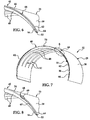
- FIGS. 5 and 6 illustrate another embodiment of the upper fuselage portion 32 in which the outer body 25 is formed of a sandwich panel construction, comprising a core 55 sandwiched between inner and outer face sheets 56, 64 respectively.
- the core 55 may comprise any suitable material and geometry such as, without limitation, flutes (not shown) or a honeycomb (not shown).
- the core 55 includes a relatively high density section 66 in the area of the crown 40, at a lower density section 62 in the sides 38.
- the high density core section 66 provides the crown 40 with additional strength and rigidity, as well as impact resistance to objects such as hail striking the top (crown 40) of the aircraft, while the aircraft is on or near the ground.
- the high and low density sections 66, 62 of the core 55 may be connected together along a scarf joint 68, although other types of joints are possible, including but not limited to a lap joint, a step-lap joint, and a butt joint.
- FIGS. 7 and 8 illustrate a further embodiment of the upper fuselage portion 32 in which the body 25 comprises a solid laminate 70 in the area of the crown 40 and a composite sandwich in the sides 38, comprising a relatively medium density core 62 sandwiched between the inner and outer face sheets 56, 64.
- the composite sandwich sides 38 transitions to the solid laminate 70 along a double scarf joint 68 formed by a ramp-down 69 in the core 62; other type of joints may be possible.
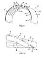
- FIGS. 9 and 10 illustrate another embodiment of the upper fuselage portion 32 which is similar to the embodiment shown in FIGS. 7 and 8 , except that the solid laminate 70 in the crown 40 is provided with longitudinally extending, high density integrated stiffeners 72 which provide the body 25 in the area of the crown 40 with additional longitudinal stiffness and stability, if required.
- the stiffeners 72 are circumferentially spaced from each other and are sandwiched between the inner and outer face sheets 56, 64 respectively. While FIG. 10 shows the stiffeners 72 as being located substantially in the middle between the inner and outer skins 56, 64, the stiffeners 72 may be located closer to the inner skin 56 or closer to the outer skin 64, if desired. In still other embodiments, such as that shown in FIG. 11 , the stiffeners 72 may be located on the inner skin 56.
- FIGS. 11 and 12 illustrate another technique for reinforcing and stiffening the crown 40 of the upper fuselage portion 32.
- circumferentially spaced, longitudinally extending composite stiffeners 74 are attached to the inner skin 56 in the area of the crown 40.
- the stiffeners 74 have a J-shaped cross section, however a variety of other cross sectional shapes are possible.
- Stiffeners 74 may be attached to the inner skin 56 by bonding or other techniques.
- the stiffeners 74 may also provide a means of attaching equipment (not shown) or subsystems (not shown) to the body 25.
- FIG. 13 illustrates another embodiment of the upper fuselage portion 32 wherein the crown 40 is provided with a longitudinally extending, centrally located backbone frame 82.
- the backbone frame 82 interconnects and may be integrally formed with the arched frame members 48 to form internal structural framework 46 that is substantially unitized and stiffened in the area of the crown 40.
- the backbone frame 82 includes a pair of integrally formed, longitudinally extending internal ducts 78 which are separated from each other by a central partition 80.
- the backbone frame 82 may comprise a composite laminate that is laid up and co-cured along with arched frame members 48 during a fabrication process that will be described below in more detail.
- ducts 78 form port and starboard air supply ducts that carry air from a source (not shown) longitudinally through the aircraft along the crown 40.
- one or more of the arched frame members 48 may include a distribution duct 84 that is held in place by a structural foam 60 filling the frame member 48.
- Each of the distribution ducts 84 is connected with one of the supply ducts 78 and functions to direct air supplied at 82 outward and downward as shown by the arrows 76 into the cabin 44.
- one or more ducts 78 formed by the backbone frame 82 may be employed to allow other utilities to be directed through the aircraft along the crown 40, including but not limited to other types of environmental control systems, wireless communications, hard electrical wiring, wireless power delivery and various systems for monitoring the structural health of the aircraft, including moisture monitoring systems.
- FIG. 15 illustrates the provision of a tray 88 attached to the lower part of the backbone frame 82 which may be used to support and route onboard subsystems such as, without limitation, electrical wiring, longitudinally through the aircraft.
- FIG. 13 illustrates ducts 78 formed by the integrated backbone frame 82
- a semi-integrated central supply conduit 85 shown in FIGS. 16 and 17 , which is located along the crown 40.
- the conduit 85 is generally oval in cross section, however other cross sectional shapes are possible.
- the conduit 85 is centrally located beneath the crown 40 and extends longitudinally through the upper fuselage portion 32.
- Each of the frame members 48 may include a recessed portion 96 having a shape substantially matching that of the conduit 85 in order to recess the conduit 85 into the frame members 48 so that the conduit 85 does not extend downwardly into the cabin 44 any more than is necessary.
- the conduit 85 may be formed of any suitable, relatively rigid material, including but not limited to composites.
- the conduit 85 may be attached to either or both the arched frame members 48 and body 25 using fasteners, bonding techniques or interlocking mechanical mechanisms (all not shown). As seen in FIG. 17 , the conduit 85 includes an internal cavity 90 through which a utility may be routed. In the illustrated example, the conduit 85 is provided with outlet openings 92 that are coupled with inlet openings 94 in the frame members 48.
- the ducts 78, 84 formed in the structural framework 46 may be used to supply and distribute any of various utilities through the aircraft.
- FIG. 18 illustrates the use of the framework ducts 78, 84 as waveguide cavities used to transmit electromagnetic signals in the form of data or power through the aircraft.
- one or more wireless transceivers 100 positioned at longitudinally spaced locations in the aircraft, may be used to transmit data or power signals through the waveguide cavity 98 (framework ducts 78, 84).
- any of a number of airplane heath monitoring sensors, energy harvesters, RFID tags, etc. collectively shown at 104 may be monitored at another location in the aircraft using the wireless transceivers 100 to transmit data signals.
- At least one of the wireless transceivers 100 may be coupled with a suitable onboard computer 106 which may function to interrogate and/or monitor the devices 104.
- the wireless transceivers 100 in combination with the waveguide cavity 98 may be used to wirelessly transmit power generated by power supply 108 through the aircraft in order to power one or more of the devices 104.
- power generated by an energy harvesting device 104 may be transmitted through the waveguide cavity 98 to batteries which may form part of the power supply 108.
- the upper fuselage portion 32 having a multifunctional crown 40 may be manufactured according to a method illustrated in FIGS. 19 and 20 .
- composite material is laid up over a double mandrel 113 using an automatic fiber placement machine or using other conventional techniques for laying up composite material over a shaped tool.
- the layup 112 is cut and separated into two substantially identical outer skins 112a, 112b.
- the outer inner skins 112a, 112b are placed in a pair of substantially identical, outer mold line tools 114, 116.
- foam cores 118a, 118b are laid up over the outer skins 112a, 112b.
- inner skins 120a, 120b are laid up over the corresponding cores 118a, 118b, using hand placement techniques or automatic fiber placement equipment (not shown). While the above described method provides for the substantially simultaneous fabrication of two fuselage portions 32 using a single double mandrel 113, the outer skins 112a, 112b may be laid up over two separate mandrels (not shown), if desired.
- the fabrication method shown in FIG. 10 may be carried out by laying prepreg fiber plies, it may also be possible to fabricate the fuselage body portions 32, or sections thereof, using dry fiber preforms (not shown) and resin infusion techniques.
- the arched frame members 48 and the backbone frame 82 may be integrally formed together using dry preforms (not shown) that are placed on the inner skins 120a shown in FIG. 19 , and then co-infused with resin.
- the arched frame members 48 are laid up over the inner skins 120a, 120b thereby forming two substantially identical body portions 32.
- the laid up upper body portions 32 are vacuum bagged, processed and cured resulting in a co-cured, unitized structure.
- the cured body portions 32 are removed from the outer mold line tools 114, 116.
- the cured body portions 32 may be trimmed, as needed following which the upper body portions 32 may be joined to pre-cured lower body portions 34 ( FIG. 1 ).
- exemplary method 140 may include specification and design 144 of the aircraft 142 and material procurement 146.
- component and subassembly manufacturing 148 and system integration 150 of the aircraft 142 takes place.
- the disclosed method and apparatus may be employed to fabricate composite parts such as fuselage sections which are then assembled at step 150.
- the aircraft 142 may go through certification and delivery 152 in order to be placed in service 154. While in service by a customer, the aircraft 142 may be scheduled for routine maintenance and service 156 (which may also include modification, reconfiguration, refurbishment, and so on).
- a system integrator may include without limitation any number of aircraft manufacturers and major-system subcontractors; a third party may include without limitation any number of vendors, subcontractors, and suppliers; and an operator may be an airline, leasing company, military entity, service organization, and so on.
- the aircraft 142 produced by exemplary method 140 may include an airframe 158 with a plurality of systems 160 and an interior 162.
- the disclosed method and apparatus may be employed to fabricate fuselage sections which form part of the airframe 158.
- Examples of high-level systems 150 include one or more of a propulsion system 164, an electrical system 166, a hydraulic system 168, and an environmental system 170. Any number of other systems may be included.
- an aerospace example is shown, the principles of the invention may be applied to other industries, such as the automotive industry.
- the apparatus embodied herein may be employed during any one or more of the stages of the production and service method 140.
- components or subassemblies corresponding to production process 148 may be fabricated or manufactured in a manner similar to components or subassemblies produced while the aircraft 142 is in service.
- one or more apparatus embodiments may be utilized during the production stages 148 and 150, for example, by substantially expediting assembly of or reducing the cost of an aircraft 142.
- one or more apparatus embodiments may be utilized while the aircraft 142 is in service, for example and without limitation, to maintenance and service 156.
Landscapes
- Engineering & Computer Science (AREA)
- Manufacturing & Machinery (AREA)
- Aviation & Aerospace Engineering (AREA)
- Mechanical Engineering (AREA)
- Transportation (AREA)
- Chemical & Material Sciences (AREA)
- Composite Materials (AREA)
- Moulding By Coating Moulds (AREA)
- Tents Or Canopies (AREA)
Abstract
Description
- This disclosure generally relates to fuselage structures, especially those formed of composites, and deals more particularly with a fuselage having a multifunctional crown.
- Polymer-based composites may be selected for use in fabricating aircraft structures because of their favorable strength-to-weight ratio. Current designs for aircraft fuselage may employ a number of composite components, including sandwich panels, frames and stiffeners, to name only a few. The assembly of these composite components during the fabrication process may be time consuming and labor intensive, consequently, it is desirable to integrate these components where possible, in order to reduce assembly time and/or labor as well as aircraft weight.
- Assembly time/labor as well as aircraft weight may also be reduced by simplifying onboard aircraft subsystems such as environmental control systems (ECS), electrical wiring and communication systems. The problem of reducing the number of composite structural components and simplifying onboard subsystems is complicated by the fact that larger commercial and military aircraft fuselages are fabricated in sections that must be joined together during the production process.
- Accordingly, there is a need for a composite aircraft fuselage having a reduced number of components requiring assembly while integrating at least portions of aircraft subsystems in order to reduce costs and aircraft weight. There is also a need for a method of fabricating a composite aircraft fuselage which allows integration of subsystems during assembly of the fuselage sections while increasing production rates.
- The disclosed embodiments provide a composite fuselage structure having a multifunctional crown that integrates one or more aircraft subsystems, thereby reducing the number of components requiring assembly. The multifunctional crown provides a unitized design exhibiting improved strength and impact resistance to object strikes, such as hail. Integration of aircraft subsystems into the multi-functional crown may result in improvements in manufacturing and structural efficiencies, energy transport and remote structural health and moisture ingress monitoring. The multifunctional fuselage crown provides shielded pathways for transmission of RF (radio frequency) through the aircraft. These shielded pathways may be used to supply RF energy to structural health monitoring sensors and/or for data communications. The pathways are formed by one or more waveguide cavities integrated into the crown which provides shielding from the ambient environment, which may reduce disruptions in communication links.
- Wireless communication through the integrated waveguide cavity may result in higher data rates, longer range, larger capacity and lower operating power. The use of the multi-function crown as a waveguide cavity may allow nondestructive evaluation (NDE) of remote areas of a unitized aircraft structure, thereby possibly obviating the need for disassembling parts of the aircraft in order to perform NDE or structural health monitoring.
- According to one disclosed embodiment, a fuselage structure comprises a fuselage body having an inner surface and framework for stiffening the body. The framework includes at least one frame member attached to the inner surface and having a duct therein for routing a utility through the body. The utility may include one or more of an environmental control system, electrical wiring, a wireless communication system, a wireless electrical power delivery system and a moisture monitoring system. The duct forms an electromagnetic energy waveguide cavity allowing wireless data transmission of electromagnetic signals through the frame member. The fuselage body includes an upper portion having a crown, a cabin beneath the crown and a lower portion. The framework includes a plurality of arched frame members attached to the upper portion of the fuselage body and extending transversely across the crown. At least certain of the frame members include an integral cavity therein extending downwardly from the crown toward the cabin. The fuselage structure may further comprise an air supply duct extending longitudinally through the body in the area of the crown and coupled with the frame member cavities. The air supply duct may be integrated into each of the arched frame members and form a portion of the framework.
- According to another disclosed embodiment, a fuselage structure comprises a body including an inner surface defining a cabin, and a plurality of circumferentially extending composite frame members around the cabin for reinforcing the body. Each of the frame members is attached to the inner surface of the fuselage body, and includes a utility service distribution duct therein for distributing a utility service to the cabin. The body may comprise composite panels, including an upper portion having a crown and a lower portion joined with the upper portion. Each of the frame members is joined to the panels in the upper portion of the body and spans the crown. The fuselage structure may further comprise a utility supply duct extending longitudinally through the body and coupled with the distribution ducts in the frame members. The utility supply duct may be integral with the frame members and is disposed between the crown and the cabin.
- According to a further embodiment, a fuselage structure comprises a body having a crown and a frame extending longitudinally through the body for stiffening the body in the area of the crown. The frame includes at least one duct therein for routing a utility through the body.
- According to a further embodiment, a method is provided of manufacturing aircraft fuselages. The method comprises laying up a composite structure over a tool and separating the composite structure into first and second fuselage skins. The method further includes forming two fuselage portions respectively using the first and second skins.
-
- 1. A fuselage structure, comprising: a fuselage body including an inner surface; and structural framework for stiffening the body, the structural framework including at least one frame member attached to the inner surface and having a duct therein for routing a utility through the body.
- 2. The fuselage structure of
clause 1, wherein the utility includes at least one of: an environmental control system, electrical wiring, a wireless communication system, a wireless electrical power delivery system, and a moisture monitoring system. - 3. The fuselage structure of
clause 1, wherein: the duct forms an electromagnetic energy waveguide cavity, and the utility includes a wireless data transmission system transmitting electromagnetic signals through the waveguide cavity. - 4. The fuselage structure of
clause 1, wherein: the fuselage body includes an upper portion having a crown, a cabin beneath the crown, and a lower portion, and the structural framework includes a plurality of arched frame members attached to the inner surface of the upper portion of the fuselage body and extending transversely across the crown, wherein at least certain of the frame members include an integral cavity therein extending downwardly from the crown toward the cabin. - 5. The fuselage structure of clause 4, further comprising: an air supply duct extending longitudinally through the body in the area of the crown and coupled with the frame member cavities.
- 6. The fuselage structure of clause 5, wherein the air supply duct is integrated into each of the arched frame members and forms a portion of the structural framework.
- 7. The fuselage structure of
clause 1, wherein the body and the structural framework are formed of composite materials. - 8. The fuselage structure of
clause 1, wherein the structural framework includes a plurality of ached frame members attached to the fuselage body and extending transversely across the crown, wherein each of the arched frame members is filed with a structural foam and includes a conduit surrounded and supported by the foam. - 9. The fuselage structure of
clause 1, wherein: the fuselage body includes an upper portion having sides and a crown formed of a composite panels, the panels including a core sandwiched between inner and outer facesheets, wherein the core has increased stiffness in the area of the crown. - 10. A fuselage structure, comprising: a body defining a cabin; and a plurality of circumferentially extending composite frame members around the cabin for reinforcing the body, each of the frame members being attached to the body and having a utility distribution duct therein for distributing a utility service to the cabin.
- 11. The fuselage structure of
clause 10, wherein: the body is formed of composite panels, the body including an upper portion having a crown, and a lower portion joined to the upper portion, wherein each of the frame members is connected to the panels in the upper portion of the body and spans the crown. - 12. The fuselage structure of clause 11, further comprising: a utility supply duct extending longitudinally through the body and coupled with the distribution ducts in the frame members.
- 13. The fuselage structure of
clause 12, wherein the utility supply duct forms a backbone frame and is integral with the frame members. - 14. The fuselage structure of
clause 12, wherein the utility supply duct is disposed between the crown and the cabin. - 15. The fuselage structure of
clause 12, wherein the utility is one of: environmental control, wireless communications, and electrical control. - 16. The fuselage structure of
clause 12, wherein:- each of the frame members is filled with a structural foam, and the ducts extend through the structural foam.
- 17. A fuselage structure, comprising: a body having a crown; and a frame extending longitudinally through the body for stiffening the body in the area of the crown, the frame including at least one duct therein for routing a utility through the body.
- 18. The fuselage of clause 17, further comprising: a plurality of longitudinally spaced, arched frame members attached to the body for stiffening the body, at least certain of the arched frame members including ducts therein coupled with the duct in the longitudinally extending frame.
- 19. The fuselage of clause 17, wherein: each of the arched frame members and the longitudinally extending frame member are formed of composite materials, and the arched frame members and the longitudinally extending frame member are formed integral with each other.
- 20. The fuselage of clause 17, wherein the utility includes at least one of: an environmental control system, electrical wiring, a wireless communication system, a wireless electrical power delivery system, and a moisture monitoring system.
- 21. The fuselage of clause 17, wherein the body and the longitudinally extending frame are each formed of a polymer-based composite.
- 22. A method of manufacturing aircraft fuselages, comprising: laying up a composite structure over a tool; separating the composite structure into first and second outer fuselage skins; and forming two fuselage portions respectively using the first and second outer skins.
- 23. The method of clause 22, wherein forming two fuselage portions respectively using the first and second outer skins includes: placing the first and second outer skins respectively first and second outer mold line tools, placing a core over each of the first and second pouter skins, and laying up a composite inner skin over each of the molds.
- 24. The method of clause 23, wherein forming two fuselage portions respectively using the first and second outer skins further includes: laying up arched composite frame members over each of the inner skins, laying up a longitudinally extending frame over each of the inner skins integrated with the arched frame members, and curing each of the fuselage portions.
- 25. A aircraft fuselage, comprising: an outer body formed of composite sandwich panels including a core sandwiched between an inner and an outer skin, the body including an upper portion having a crown and a lower portion joined to the upper portion along a longitudinally extending joint, wherein the core has a section of increased strength in the area of the crown; a plurality of longitudinally spaced composite arched frame members joined to the inner skin of the panels in the upper portion of the body for stiffening the body in the area of the crown, at least certain of the arched frame members including a duct therein for distributing air downwardly from the area of the crown; and a longitudinally extending composite backbone frame formed integral with the arched frame members and attached to the inner skin in the area of the crown, the backbone frame including an internal duct coupled with the ducts in the arched frame members.
- 26. A method of manufacturing aircraft fuselages, comprising: laying up a composite structure over a double mandrel; cutting the composite structure into first and second outer fuselage skins; placing the first and second outer skins respectively first and second outer mold line tools; placing a core over each of the first and second outer skins; laying up a composite inner skin over each of the cores; laying up arched composite frame members over each of the inner skins; laying up a longitudinally extending composite frame over each of the inner skins integrated with the arched frame members to form two upper fuselage portions; curing each of the upper fuselage portions; and joining two lower fuselage portions respectively to the upper fuselage portions to for two fuselage sections.
-
-
FIG. 1 is an illustration of a perspective view of an aircraft fuselage section having a multifunctional crown. -
FIG. 2 is an illustration of a view similar toFIG. 1 but with the outer body panels having been removed to reveal the framework. -
FIG. 3 is an illustration of a perspective view of an upper portion of the fuselage section shown inFIG. 1 . -
FIG. 4 is an illustration of a sectional view taken along the line 4-4 inFIG. 3 . -
FIG. 5 is an illustration of a perspective view similar toFIG. 3 but showing an alternate form of body panel construction. -
FIG. 6 is an illustration of the area designated as "6" inFIG. 5 . -
FIG. 7 is an illustration similar toFIG. 3 but showing a further embodiment of the body panel construction. -
FIG. 8 is an illustration of the area designated as "8" inFIG. 7 . -
FIG. 9 is an illustration of a perspective view similar toFIG. 3 but showing another embodiment of the body panel construction. -
FIG. 10 is an illustration of the area designated as "10" inFIG. 9 . -
FIG. 11 is an illustration of a perspective view of an upper body portion having a crown reinforced by internal stiffeners. -
FIG. 12 is an illustration of the area designated as "12" inFIG. 11 . -
FIG. 13 is an illustration of a perspective view of another embodiment of the upper portion of a fuselage section employing a multifunctional crown. -
FIG. 14 is an illustration of a perspective sectional view taken along the line 14-14 inFIG. 13 . -
FIG. 15 is an illustration of an end view of an alternate form of the multifunctional crown. -
FIG. 16 is an illustration of a perspective view of an upper portion of the fuselage section employing another form of the multifunctional crown. -
FIG. 17 is an illustration of a perspective view of the multifunctional crown shown inFIG. 16 , parts being broken away in section to review the connections between the supply duct and the distribution ducts. -
FIG. 18 is an illustration of a functional block diagram of a wireless transmission system used in fuselage structures employing the multifunctional crown. -
FIG. 19 is an illustration of perspective views of components, showing the steps of a method of making fuselage structures. -
FIG. 20 is an illustration of a flow diagram of the manufacturing method illustrated inFIG. 19 . -
FIG. 21 is a flow diagram of aircraft production and service methodology. -
FIG. 22 is a block diagram of an aircraft. - Referring first to
FIGS. 1 and 2 , a barrel-shapedfuselage section 30 comprises upper andlower fuselage portions portions unitized floor 42. During the fabrication of an aircraft (not shown), two or more of the barrel-shapedfuselage sections 30 may be joined together end-to-end to form a complete fuselage (not shown). Theupper fuselage portion 32 includessides 38 and acrown 40. As will be discussed below in more detail, each of thefuselage portions outer body 25 that includes aninner skin 56 defining an inner surface of thebody 25 and anouter skin 64. In other embodiments, thebody 25 may be formed of asingle skin 56, rather than composite sandwich panels. Although the illustratedfuselage section 30 has a generally circular cross sectional shape, a variety of other cross-sectional shapes and combinations of shapes are possible, including but not limited to oval and other shapes. - The
floor 42 is supported by one or more frames (not shown) or other supports (not shown) forming part of thefuselage section 30. In the illustrated embodiment,fuselage section 30 includes asingle floor 42 extending across thefuselage section 30 at the level of the joint 36 to define anupper cabin 44, however, more than onefloor 42 is possible. Theupper portion 32 of thefuselage section 30 is reinforced bystructural framework 46 comprising a plurality of longitudinally spaced, archedstructural frame members 48 which are joined to the inner surface of thebody 25 defined by theinner skin 56.Frame members 48 extend circumferentially around substantially the entire perimeter of theupper fuselage portion 32, but may haveextremities 50 that taper in cross sectional area in the area of thesides 38. - Depending upon the particular application and aircraft geometry, the
structural framework 46 may include additionalarched frame members 48a around openings such as thedoorway 54 in thefuselage section 30. Depending upon structural loads of the application, thearch frame members 48 may vary in cross-sectional dimensions, overall height and length, and spacing from each other. Although not shown inFIGS. 1 and 2 , thestructural framework 46 may include a longitudinally extending backbone frame member in the area of thecrown 40 which structurally joins theframe members 40 together and provides thefuselage section 30 with rigidity in the longitudinal direction of the aircraft. Additional details of asuitable fuselage section 30 of the type described above may be found inUS Patent 7,735,779 issued on June 15, 2010 , the entire contents of which are incorporated by reference herein. -
FIGS. 3 and 4 illustrate one embodiment of theupper fuselage portion 32 having anouter body 25 formed of a solid, polymer basedlaminate 35 such as, for example and without limitation, carbon fiber reinforced epoxy. Thesides 38 and thecrown 40 are reinforced by composite,arched frame members 48. Each of theframe members 48 may have a cross section suited for the application. In the illustrated example, each of theframe members 48 is hat-shaped in cross section and includesouter flanges 58 that are secured to theinner skin 56 through co-curing, bonding and/or fasteners (not shown). For simplicity, theflanges 58 are omitted fromFIGS. 3, 5 ,7 ,9 ,11, 13 ,16 and 17 .Frames members 48 may be filled with a suitablestructural foam 60. -
FIGS. 5 and6 illustrate another embodiment of theupper fuselage portion 32 in which theouter body 25 is formed of a sandwich panel construction, comprising a core 55 sandwiched between inner andouter face sheets core 55 includes a relativelyhigh density section 66 in the area of thecrown 40, at alower density section 62 in thesides 38. The highdensity core section 66 provides thecrown 40 with additional strength and rigidity, as well as impact resistance to objects such as hail striking the top (crown 40) of the aircraft, while the aircraft is on or near the ground. The high andlow density sections -
FIGS. 7 and 8 illustrate a further embodiment of theupper fuselage portion 32 in which thebody 25 comprises asolid laminate 70 in the area of thecrown 40 and a composite sandwich in thesides 38, comprising a relativelymedium density core 62 sandwiched between the inner andouter face sheets solid laminate 70 along a double scarf joint 68 formed by a ramp-down 69 in thecore 62; other type of joints may be possible. -
FIGS. 9 and 10 illustrate another embodiment of theupper fuselage portion 32 which is similar to the embodiment shown inFIGS. 7 and 8 , except that thesolid laminate 70 in thecrown 40 is provided with longitudinally extending, high densityintegrated stiffeners 72 which provide thebody 25 in the area of thecrown 40 with additional longitudinal stiffness and stability, if required. In this example, thestiffeners 72 are circumferentially spaced from each other and are sandwiched between the inner andouter face sheets FIG. 10 shows thestiffeners 72 as being located substantially in the middle between the inner andouter skins stiffeners 72 may be located closer to theinner skin 56 or closer to theouter skin 64, if desired. In still other embodiments, such as that shown inFIG. 11 , thestiffeners 72 may be located on theinner skin 56. -
FIGS. 11 and 12 illustrate another technique for reinforcing and stiffening thecrown 40 of theupper fuselage portion 32. In this embodiment, circumferentially spaced, longitudinally extendingcomposite stiffeners 74 are attached to theinner skin 56 in the area of thecrown 40. In the illustrated example, thestiffeners 74 have a J-shaped cross section, however a variety of other cross sectional shapes are possible.Stiffeners 74 may be attached to theinner skin 56 by bonding or other techniques. Thestiffeners 74 may also provide a means of attaching equipment (not shown) or subsystems (not shown) to thebody 25. -
FIG. 13 illustrates another embodiment of theupper fuselage portion 32 wherein thecrown 40 is provided with a longitudinally extending, centrally locatedbackbone frame 82. Thebackbone frame 82 interconnects and may be integrally formed with thearched frame members 48 to form internalstructural framework 46 that is substantially unitized and stiffened in the area of thecrown 40. In this example, thebackbone frame 82 includes a pair of integrally formed, longitudinally extendinginternal ducts 78 which are separated from each other by acentral partition 80. Thebackbone frame 82 may comprise a composite laminate that is laid up and co-cured along witharched frame members 48 during a fabrication process that will be described below in more detail. In the illustrated embodiment,ducts 78 form port and starboard air supply ducts that carry air from a source (not shown) longitudinally through the aircraft along thecrown 40. - As shown in
FIG. 14 , one or more of thearched frame members 48 may include adistribution duct 84 that is held in place by astructural foam 60 filling theframe member 48. Each of thedistribution ducts 84 is connected with one of thesupply ducts 78 and functions to direct air supplied at 82 outward and downward as shown by thearrows 76 into thecabin 44. As will be discussed below in more detail, one ormore ducts 78 formed by thebackbone frame 82 may be employed to allow other utilities to be directed through the aircraft along thecrown 40, including but not limited to other types of environmental control systems, wireless communications, hard electrical wiring, wireless power delivery and various systems for monitoring the structural health of the aircraft, including moisture monitoring systems. -
FIG. 15 illustrates the provision of atray 88 attached to the lower part of thebackbone frame 82 which may be used to support and route onboard subsystems such as, without limitation, electrical wiring, longitudinally through the aircraft. - While
FIG. 13 illustratesducts 78 formed by theintegrated backbone frame 82, it may be possible to distribute utility services through theframe members 48 using a semi-integratedcentral supply conduit 85 shown inFIGS. 16 and 17 , which is located along thecrown 40. In this example, theconduit 85 is generally oval in cross section, however other cross sectional shapes are possible. Theconduit 85 is centrally located beneath thecrown 40 and extends longitudinally through theupper fuselage portion 32. Each of theframe members 48 may include a recessedportion 96 having a shape substantially matching that of theconduit 85 in order to recess theconduit 85 into theframe members 48 so that theconduit 85 does not extend downwardly into thecabin 44 any more than is necessary. Theconduit 85 may be formed of any suitable, relatively rigid material, including but not limited to composites. - The
conduit 85 may be attached to either or both thearched frame members 48 andbody 25 using fasteners, bonding techniques or interlocking mechanical mechanisms (all not shown). As seen inFIG. 17 , theconduit 85 includes aninternal cavity 90 through which a utility may be routed. In the illustrated example, theconduit 85 is provided withoutlet openings 92 that are coupled withinlet openings 94 in theframe members 48. - Referring now to
FIG. 18 , as previously mentioned, theducts structural framework 46 may be used to supply and distribute any of various utilities through the aircraft.FIG. 18 illustrates the use of theframework ducts wireless transceivers 100 positioned at longitudinally spaced locations in the aircraft, may be used to transmit data or power signals through the waveguide cavity 98 (framework ducts 78, 84). For example, any of a number of airplane heath monitoring sensors, energy harvesters, RFID tags, etc. collectively shown at 104, may be monitored at another location in the aircraft using thewireless transceivers 100 to transmit data signals. - At least one of the
wireless transceivers 100 may be coupled with a suitableonboard computer 106 which may function to interrogate and/or monitor thedevices 104. Thewireless transceivers 100 in combination with thewaveguide cavity 98 may be used to wirelessly transmit power generated bypower supply 108 through the aircraft in order to power one or more of thedevices 104. Alternatively, power generated by anenergy harvesting device 104 may be transmitted through thewaveguide cavity 98 to batteries which may form part of thepower supply 108. - The
upper fuselage portion 32 having amultifunctional crown 40 may be manufactured according to a method illustrated inFIGS. 19 and20 . Beginning at 122, composite material is laid up over adouble mandrel 113 using an automatic fiber placement machine or using other conventional techniques for laying up composite material over a shaped tool. At 124, thelayup 112 is cut and separated into two substantially identicalouter skins inner skins mold line tools foam cores outer skins step 130,inner skins cores fuselage portions 32 using a singledouble mandrel 113, theouter skins - While the fabrication method shown in
FIG. 10 may be carried out by laying prepreg fiber plies, it may also be possible to fabricate thefuselage body portions 32, or sections thereof, using dry fiber preforms (not shown) and resin infusion techniques. For example, and without limitation, thearched frame members 48 and thebackbone frame 82 may be integrally formed together using dry preforms (not shown) that are placed on theinner skins 120a shown inFIG. 19 , and then co-infused with resin. - At 132, the
arched frame members 48 are laid up over theinner skins identical body portions 32. Atstep 133 shown inFIG. 20 , the laid upupper body portions 32 are vacuum bagged, processed and cured resulting in a co-cured, unitized structure. At 134, the curedbody portions 32 are removed from the outermold line tools body portions 32 may be trimmed, as needed following which theupper body portions 32 may be joined to pre-cured lower body portions 34 (FIG. 1 ). - Referring next to
FIGS. 21 and 22 , embodiments of the disclosure may be used in the context of an aircraft manufacturing andservice method 140 as shown inFIG. 21 and anaircraft 142 as shown inFIG. 22 . During pre-production,exemplary method 140 may include specification anddesign 144 of theaircraft 142 andmaterial procurement 146. During production, component andsubassembly manufacturing 148 andsystem integration 150 of theaircraft 142 takes place. Duringstep 148, the disclosed method and apparatus may be employed to fabricate composite parts such as fuselage sections which are then assembled atstep 150. Thereafter, theaircraft 142 may go through certification anddelivery 152 in order to be placed inservice 154. While in service by a customer, theaircraft 142 may be scheduled for routine maintenance and service 156 (which may also include modification, reconfiguration, refurbishment, and so on). - Each of the processes of
method 140 may be performed or carried out by a system integrator, a third party, and/or an operator (e.g., a customer). For the purposes of this description, a system integrator may include without limitation any number of aircraft manufacturers and major-system subcontractors; a third party may include without limitation any number of vendors, subcontractors, and suppliers; and an operator may be an airline, leasing company, military entity, service organization, and so on. - As shown in
FIG. 22 , theaircraft 142 produced byexemplary method 140 may include anairframe 158 with a plurality ofsystems 160 and an interior 162. The disclosed method and apparatus may be employed to fabricate fuselage sections which form part of theairframe 158. Examples of high-level systems 150 include one or more of apropulsion system 164, anelectrical system 166, ahydraulic system 168, and anenvironmental system 170. Any number of other systems may be included. Although an aerospace example is shown, the principles of the invention may be applied to other industries, such as the automotive industry. - The apparatus embodied herein may be employed during any one or more of the stages of the production and
service method 140. For example, components or subassemblies corresponding toproduction process 148 may be fabricated or manufactured in a manner similar to components or subassemblies produced while theaircraft 142 is in service. Also, one or more apparatus embodiments may be utilized during the production stages 148 and 150, for example, by substantially expediting assembly of or reducing the cost of anaircraft 142. Similarly, one or more apparatus embodiments may be utilized while theaircraft 142 is in service, for example and without limitation, to maintenance andservice 156. - Although the embodiments of this disclosure have been described with respect to certain exemplary embodiments, it is to be understood that the specific embodiments are for purposes of illustration and not limitation, as other variations will occur to those of skill in the art.
Claims (12)
- A fuselage structure, comprising:a fuselage body including an inner surface; andstructural framework for stiffening the body, the structural framework including at least one frame member attached to the inner surface and having a duct therein for routing a utility through the body.
- The fuselage structure of claim 1, wherein the utility includes at least one of:an environmental control system,electrical wiring,a wireless communication system,a wireless electrical power delivery system, anda moisture monitoring system.
- The fuselage structure of claim 1, wherein:the duct forms an electromagnetic energy waveguide cavity, andthe utility includes a wireless data transmission system transmitting electromagnetic signals through the waveguide cavity.
- The fuselage structure of claim 1, wherein:the fuselage body includes an upper portion having a crown, a cabin beneath the crown, and a lower portion, andthe structural framework includes a plurality of arched frame members attached to the inner surface of the upper portion of the fuselage body and extending transversely across the crown, wherein at least certain of the frame members include an integral cavity therein extending downwardly from the crown toward the cabin.
- The fuselage structure of claim 4, further comprising:an air supply duct extending longitudinally through the body in the area of the crown and coupled with the frame member cavities.
- The fuselage structure of claim 5, wherein the air supply duct is integrated into each of the arched frame members and forms a portion of the structural framework.
- The fuselage structure of claim 1, wherein the body and the structural framework are formed of composite materials.
- The fuselage structure of claim 1, wherein the structural framework includes a plurality of ached frame members attached to the fuselage body and extending transversely across the crown, wherein each of the arched frame members is filed with a structural foam and includes a conduit surrounded and supported by the foam.
- The fuselage structure of claim 1, wherein:the fuselage body includes an upper portion having sides and a crown formed of a composite panels, the panels including a core sandwiched between inner and outer facesheets, wherein the core has increased stiffness in the area of the crown.
- A method of manufacturing aircraft fuselages, comprising:laying up a composite structure over a tool;separating the composite structure into first and second outer fuselage skins; andforming two fuselage portions respectively using the first and second outer skins.
- The method of claim 10, wherein forming two fuselage portions respectively using the first and second outer skins includes:placing the first and second outer skins respectively first and second outer mold line tools,placing a core over each of the first and second pouter skins, andlaying up a composite inner skin over each of the molds.
- The method of claim 11, wherein forming two fuselage portions respectively using the first and second outer skins further includes:laying up arched composite frame members over each of the inner skins,laying up a longitudinally extending frame over each of the inner skins integrated with the arched frame members, andcuring each of the fuselage portions.
Applications Claiming Priority (1)
| Application Number | Priority Date | Filing Date | Title |
|---|---|---|---|
| US12/944,113 US8752791B2 (en) | 2010-11-11 | 2010-11-11 | Fuselage employing multifunctional crown and method of making the same |
Publications (3)
| Publication Number | Publication Date |
|---|---|
| EP2452872A2 true EP2452872A2 (en) | 2012-05-16 |
| EP2452872A3 EP2452872A3 (en) | 2017-10-04 |
| EP2452872B1 EP2452872B1 (en) | 2019-08-28 |
Family
ID=44905700
Family Applications (1)
| Application Number | Title | Priority Date | Filing Date |
|---|---|---|---|
| EP11187923.5A Active EP2452872B1 (en) | 2010-11-11 | 2011-11-04 | Fuselage employing multifunctional crown and method of making the same |
Country Status (4)
| Country | Link |
|---|---|
| US (1) | US8752791B2 (en) |
| EP (1) | EP2452872B1 (en) |
| JP (1) | JP6039175B2 (en) |
| CN (1) | CN102530234B (en) |
Cited By (2)
| Publication number | Priority date | Publication date | Assignee | Title |
|---|---|---|---|---|
| EP2979975A1 (en) * | 2014-07-30 | 2016-02-03 | AIRBUS HELICOPTERS DEUTSCHLAND GmbH | An aircraft with a framework structure that comprises at least one hollow frame. |
| DE102017112594A1 (en) * | 2017-06-08 | 2018-12-13 | Airbus Operations Gmbh | Air distribution system for an aircraft cabin |
Families Citing this family (10)
| Publication number | Priority date | Publication date | Assignee | Title |
|---|---|---|---|---|
| DE102007050422B4 (en) * | 2007-10-22 | 2012-03-08 | Airbus Operations Gmbh | Aircraft component assembly system |
| USD732459S1 (en) * | 2013-05-21 | 2015-06-23 | Airbus Corporate Jet Centre | Aircraft cabin |
| US20180072433A1 (en) * | 2015-03-23 | 2018-03-15 | Bombardier Inc. | Simulation of loads on aerostructures during aircraft assembly |
| EP3521002B1 (en) | 2016-09-29 | 2023-11-01 | Subaru Corporation | Composite material structure and method for manufacturing composite material structure |
| CN106596003B (en) * | 2016-11-29 | 2019-04-23 | 中国航空工业集团公司沈阳飞机设计研究所 | A kind of composite airplane frame sections pressurising test method |
| US11220353B2 (en) * | 2019-04-18 | 2022-01-11 | The Boeing Company | Method of fabricating a composite structure |
| EP3978358B1 (en) * | 2020-09-30 | 2024-11-06 | The Boeing Company | Aircraft fuselage longitudinal splice for joining half barrel fuselage sections and other spliced fuselage sections |
| US11866200B2 (en) * | 2020-11-18 | 2024-01-09 | The Boeing Company | Pulsed line fabrication for a fuselage using work stations |
| US11872780B2 (en) | 2022-06-02 | 2024-01-16 | The Boeing Company | Methods and tool for cutting an uncured composite material |
| DE102022133280A1 (en) * | 2022-12-14 | 2024-06-20 | Airbus Operations Gmbh | Component with waveguide, data transmission system and aircraft |
Citations (1)
| Publication number | Priority date | Publication date | Assignee | Title |
|---|---|---|---|---|
| US7735779B2 (en) | 2006-11-02 | 2010-06-15 | The Boeing Company | Optimized fuselage structure |
Family Cites Families (24)
| Publication number | Priority date | Publication date | Assignee | Title |
|---|---|---|---|---|
| JPH04329125A (en) * | 1991-04-30 | 1992-11-17 | Mitsubishi Heavy Ind Ltd | Monolithic molding method of composite |
| JPH1016085A (en) * | 1996-07-04 | 1998-01-20 | Mitsubishi Heavy Ind Ltd | Manufacture of fuselage skin of airplane |
| JP4318381B2 (en) * | 2000-04-27 | 2009-08-19 | 本田技研工業株式会社 | Manufacturing method of fuselage structure made of fiber reinforced composite material, and fuselage structure manufactured thereby |
| DE10154063B4 (en) * | 2001-11-02 | 2013-11-28 | Airbus Operations Gmbh | Double-walled core composite, preferably fiber composite |
| US7380752B2 (en) | 2003-10-17 | 2008-06-03 | The Boeing Company | Aircraft interior architecture |
| US7252267B2 (en) * | 2003-10-17 | 2007-08-07 | The Boeing Company | Aircraft archway architecture |
| US7228611B2 (en) * | 2003-11-18 | 2007-06-12 | The Boeing Company | Method of transferring large uncured composite laminates |
| US7166251B2 (en) * | 2004-12-01 | 2007-01-23 | The Boeing Company | Segmented flexible barrel lay-up mandrel |
| USD539210S1 (en) | 2005-04-28 | 2007-03-27 | The Boeing Company | Modular archway for an aircraft |
| JP4800672B2 (en) * | 2005-06-09 | 2011-10-26 | 株式会社竹中工務店 | Path structure |
| DE102005043898A1 (en) * | 2005-09-14 | 2007-03-22 | Airbus Deutschland Gmbh | Window arrangement for e.g. passenger aircraft, has mounting element formed for feeding fluids and having transparent region that overlaps part of window region in such a manner that optical light waves are let to pass |
| US9359061B2 (en) * | 2005-10-31 | 2016-06-07 | The Boeing Company | Compliant stiffener for aircraft fuselage |
| DE102005054869A1 (en) * | 2005-11-17 | 2007-05-31 | Airbus Deutschland Gmbh | Method for producing a fuselage cell of an aircraft |
| DE102006002248B4 (en) * | 2006-01-17 | 2008-01-03 | Airbus Deutschland Gmbh | Structural construction for a fuselage |
| JP2008028549A (en) * | 2006-07-19 | 2008-02-07 | Taisei Corp | Communication wave carrier waveguide |
| DE102006039292B4 (en) * | 2006-08-22 | 2010-07-22 | Airbus Deutschland Gmbh | Frame element, aircraft air conditioning system and method for mounting a frame member in an aircraft |
| US7861970B2 (en) | 2006-11-02 | 2011-01-04 | The Boeing Company | Fuselage structure including an integrated fuselage stanchion |
| DE102007003277B4 (en) * | 2007-01-23 | 2012-08-02 | Airbus Operations Gmbh | Hull of an aircraft or spacecraft in CFRP metal. Hybrid construction with a metal frame |
| DE102007049926A1 (en) * | 2007-10-18 | 2009-04-23 | Airbus Deutschland Gmbh | System and method for air conditioning at least a portion of an aircraft |
| US7879276B2 (en) * | 2007-11-08 | 2011-02-01 | The Boeing Company | Foam stiffened hollow composite stringer |
| US8040243B2 (en) | 2008-11-18 | 2011-10-18 | The Boeing Company | RFID-based corrosion and moisture detection |
| US8421692B2 (en) * | 2009-02-25 | 2013-04-16 | The Boeing Company | Transmitting power and data |
| US8500066B2 (en) * | 2009-06-12 | 2013-08-06 | The Boeing Company | Method and apparatus for wireless aircraft communications and power system using fuselage stringers |
| US8570152B2 (en) * | 2009-07-23 | 2013-10-29 | The Boeing Company | Method and apparatus for wireless sensing with power harvesting of a wireless signal |
-
2010
- 2010-11-11 US US12/944,113 patent/US8752791B2/en active Active
-
2011
- 2011-11-04 EP EP11187923.5A patent/EP2452872B1/en active Active
- 2011-11-09 JP JP2011245427A patent/JP6039175B2/en active Active
- 2011-11-11 CN CN201110365139.2A patent/CN102530234B/en active Active
Patent Citations (1)
| Publication number | Priority date | Publication date | Assignee | Title |
|---|---|---|---|---|
| US7735779B2 (en) | 2006-11-02 | 2010-06-15 | The Boeing Company | Optimized fuselage structure |
Cited By (3)
| Publication number | Priority date | Publication date | Assignee | Title |
|---|---|---|---|---|
| EP2979975A1 (en) * | 2014-07-30 | 2016-02-03 | AIRBUS HELICOPTERS DEUTSCHLAND GmbH | An aircraft with a framework structure that comprises at least one hollow frame. |
| US9873512B2 (en) | 2014-07-30 | 2018-01-23 | Airbus Helicopters Deutschland GmbH | Aircraft framework structure with integral ventilation air duct |
| DE102017112594A1 (en) * | 2017-06-08 | 2018-12-13 | Airbus Operations Gmbh | Air distribution system for an aircraft cabin |
Also Published As
| Publication number | Publication date |
|---|---|
| CN102530234A (en) | 2012-07-04 |
| EP2452872A3 (en) | 2017-10-04 |
| US20120119028A1 (en) | 2012-05-17 |
| JP2012101787A (en) | 2012-05-31 |
| EP2452872B1 (en) | 2019-08-28 |
| CN102530234B (en) | 2015-04-29 |
| US8752791B2 (en) | 2014-06-17 |
| JP6039175B2 (en) | 2016-12-07 |
Similar Documents
| Publication | Publication Date | Title |
|---|---|---|
| US8752791B2 (en) | Fuselage employing multifunctional crown and method of making the same | |
| EP2585287B1 (en) | Composite structures having integrated stiffeners and method of making the same | |
| CA2835892C (en) | Method and device for transporting, placing and compacting composite stiffeners | |
| EP2386483B1 (en) | Curved composite frames and method of making the same | |
| EP2865516B1 (en) | Skin-stiffened composite panel and method of its manufacture | |
| CN106275370B (en) | Reinforced fuselage component and method and device for producing a reinforced fuselage component | |
| EP2881238B1 (en) | Aerospace structural member with hybrid composite structure | |
| EP2669186A2 (en) | Bonded composite airfoil and fabrication method | |
| EP2604405A1 (en) | Method and apparatus for fabricating large scale integrated airfoils | |
| AU2011269749A1 (en) | Composite structures having integrated stiffeners and method of making the same | |
| US10549490B2 (en) | Method for manufacturing a stiffened panel made from composite material | |
| EP3517425B1 (en) | Wing having wing rib, and method for manufacturing the same | |
| JP2012101787A5 (en) | ||
| EP3453525B1 (en) | Method and apparatus for manufacturing stiffened composite sandwich panels | |
| EP2848518B1 (en) | Carbon fiber reinforced polymer cargo beam with integrated cargo stanchions and c-splices | |
| US20220315212A1 (en) | Distributed propulsion structure | |
| CN219487727U (en) | Integrated fiber composite attitude control cabin | |
| US11267584B2 (en) | Method for manufacturing a rear section of an aircraft and aircraft rear section |
Legal Events
| Date | Code | Title | Description |
|---|---|---|---|
| PUAI | Public reference made under article 153(3) epc to a published international application that has entered the european phase |
Free format text: ORIGINAL CODE: 0009012 |
|
| 17P | Request for examination filed |
Effective date: 20111104 |
|
| AK | Designated contracting states |
Kind code of ref document: A2 Designated state(s): AL AT BE BG CH CY CZ DE DK EE ES FI FR GB GR HR HU IE IS IT LI LT LU LV MC MK MT NL NO PL PT RO RS SE SI SK SM TR |
|
| AX | Request for extension of the european patent |
Extension state: BA ME |
|
| RIC1 | Information provided on ipc code assigned before grant |
Ipc: B64C 1/06 20060101AFI20170609BHEP |
|
| PUAL | Search report despatched |
Free format text: ORIGINAL CODE: 0009013 |
|
| AK | Designated contracting states |
Kind code of ref document: A3 Designated state(s): AL AT BE BG CH CY CZ DE DK EE ES FI FR GB GR HR HU IE IS IT LI LT LU LV MC MK MT NL NO PL PT RO RS SE SI SK SM TR |
|
| AX | Request for extension of the european patent |
Extension state: BA ME |
|
| RIC1 | Information provided on ipc code assigned before grant |
Ipc: B64C 1/06 20060101AFI20170828BHEP |
|
| GRAP | Despatch of communication of intention to grant a patent |
Free format text: ORIGINAL CODE: EPIDOSNIGR1 |
|
| STAA | Information on the status of an ep patent application or granted ep patent |
Free format text: STATUS: GRANT OF PATENT IS INTENDED |
|
| INTG | Intention to grant announced |
Effective date: 20190308 |
|
| GRAS | Grant fee paid |
Free format text: ORIGINAL CODE: EPIDOSNIGR3 |
|
| GRAA | (expected) grant |
Free format text: ORIGINAL CODE: 0009210 |
|
| STAA | Information on the status of an ep patent application or granted ep patent |
Free format text: STATUS: THE PATENT HAS BEEN GRANTED |
|
| AK | Designated contracting states |
Kind code of ref document: B1 Designated state(s): AL AT BE BG CH CY CZ DE DK EE ES FI FR GB GR HR HU IE IS IT LI LT LU LV MC MK MT NL NO PL PT RO RS SE SI SK SM TR |
|
| REG | Reference to a national code |
Ref country code: GB Ref legal event code: FG4D |
|
| REG | Reference to a national code |
Ref country code: CH Ref legal event code: EP |
|
| REG | Reference to a national code |
Ref country code: AT Ref legal event code: REF Ref document number: 1172075 Country of ref document: AT Kind code of ref document: T Effective date: 20190915 |
|
| REG | Reference to a national code |
Ref country code: IE Ref legal event code: FG4D |
|
| REG | Reference to a national code |
Ref country code: DE Ref legal event code: R096 Ref document number: 602011061568 Country of ref document: DE |
|
| REG | Reference to a national code |
Ref country code: NL Ref legal event code: MP Effective date: 20190828 |
|
| REG | Reference to a national code |
Ref country code: LT Ref legal event code: MG4D |
|
| REG | Reference to a national code |
Ref country code: DE Ref legal event code: R082 Ref document number: 602011061568 Country of ref document: DE Representative=s name: MAIER, LL.M., MICHAEL C., DE Ref country code: DE Ref legal event code: R082 Ref document number: 602011061568 Country of ref document: DE Representative=s name: BOULT WADE TENNANT LLP, DE |
|
| PG25 | Lapsed in a contracting state [announced via postgrant information from national office to epo] |
Ref country code: PT Free format text: LAPSE BECAUSE OF FAILURE TO SUBMIT A TRANSLATION OF THE DESCRIPTION OR TO PAY THE FEE WITHIN THE PRESCRIBED TIME-LIMIT Effective date: 20191230 Ref country code: HR Free format text: LAPSE BECAUSE OF FAILURE TO SUBMIT A TRANSLATION OF THE DESCRIPTION OR TO PAY THE FEE WITHIN THE PRESCRIBED TIME-LIMIT Effective date: 20190828 Ref country code: FI Free format text: LAPSE BECAUSE OF FAILURE TO SUBMIT A TRANSLATION OF THE DESCRIPTION OR TO PAY THE FEE WITHIN THE PRESCRIBED TIME-LIMIT Effective date: 20190828 Ref country code: LT Free format text: LAPSE BECAUSE OF FAILURE TO SUBMIT A TRANSLATION OF THE DESCRIPTION OR TO PAY THE FEE WITHIN THE PRESCRIBED TIME-LIMIT Effective date: 20190828 Ref country code: SE Free format text: LAPSE BECAUSE OF FAILURE TO SUBMIT A TRANSLATION OF THE DESCRIPTION OR TO PAY THE FEE WITHIN THE PRESCRIBED TIME-LIMIT Effective date: 20190828 Ref country code: NO Free format text: LAPSE BECAUSE OF FAILURE TO SUBMIT A TRANSLATION OF THE DESCRIPTION OR TO PAY THE FEE WITHIN THE PRESCRIBED TIME-LIMIT Effective date: 20191128 Ref country code: BG Free format text: LAPSE BECAUSE OF FAILURE TO SUBMIT A TRANSLATION OF THE DESCRIPTION OR TO PAY THE FEE WITHIN THE PRESCRIBED TIME-LIMIT Effective date: 20191128 Ref country code: NL Free format text: LAPSE BECAUSE OF FAILURE TO SUBMIT A TRANSLATION OF THE DESCRIPTION OR TO PAY THE FEE WITHIN THE PRESCRIBED TIME-LIMIT Effective date: 20190828 |
|
| REG | Reference to a national code |
Ref country code: DE Ref legal event code: R082 Ref document number: 602011061568 Country of ref document: DE Representative=s name: BOULT WADE TENNANT LLP, DE |
|
| PG25 | Lapsed in a contracting state [announced via postgrant information from national office to epo] |
Ref country code: RS Free format text: LAPSE BECAUSE OF FAILURE TO SUBMIT A TRANSLATION OF THE DESCRIPTION OR TO PAY THE FEE WITHIN THE PRESCRIBED TIME-LIMIT Effective date: 20190828 Ref country code: LV Free format text: LAPSE BECAUSE OF FAILURE TO SUBMIT A TRANSLATION OF THE DESCRIPTION OR TO PAY THE FEE WITHIN THE PRESCRIBED TIME-LIMIT Effective date: 20190828 Ref country code: ES Free format text: LAPSE BECAUSE OF FAILURE TO SUBMIT A TRANSLATION OF THE DESCRIPTION OR TO PAY THE FEE WITHIN THE PRESCRIBED TIME-LIMIT Effective date: 20190828 Ref country code: AL Free format text: LAPSE BECAUSE OF FAILURE TO SUBMIT A TRANSLATION OF THE DESCRIPTION OR TO PAY THE FEE WITHIN THE PRESCRIBED TIME-LIMIT Effective date: 20190828 Ref country code: GR Free format text: LAPSE BECAUSE OF FAILURE TO SUBMIT A TRANSLATION OF THE DESCRIPTION OR TO PAY THE FEE WITHIN THE PRESCRIBED TIME-LIMIT Effective date: 20191129 Ref country code: IS Free format text: LAPSE BECAUSE OF FAILURE TO SUBMIT A TRANSLATION OF THE DESCRIPTION OR TO PAY THE FEE WITHIN THE PRESCRIBED TIME-LIMIT Effective date: 20191228 |
|
| REG | Reference to a national code |
Ref country code: AT Ref legal event code: MK05 Ref document number: 1172075 Country of ref document: AT Kind code of ref document: T Effective date: 20190828 |
|
| PG25 | Lapsed in a contracting state [announced via postgrant information from national office to epo] |
Ref country code: TR Free format text: LAPSE BECAUSE OF FAILURE TO SUBMIT A TRANSLATION OF THE DESCRIPTION OR TO PAY THE FEE WITHIN THE PRESCRIBED TIME-LIMIT Effective date: 20190828 |
|
| PG25 | Lapsed in a contracting state [announced via postgrant information from national office to epo] |
Ref country code: DK Free format text: LAPSE BECAUSE OF FAILURE TO SUBMIT A TRANSLATION OF THE DESCRIPTION OR TO PAY THE FEE WITHIN THE PRESCRIBED TIME-LIMIT Effective date: 20190828 Ref country code: PL Free format text: LAPSE BECAUSE OF FAILURE TO SUBMIT A TRANSLATION OF THE DESCRIPTION OR TO PAY THE FEE WITHIN THE PRESCRIBED TIME-LIMIT Effective date: 20190828 Ref country code: EE Free format text: LAPSE BECAUSE OF FAILURE TO SUBMIT A TRANSLATION OF THE DESCRIPTION OR TO PAY THE FEE WITHIN THE PRESCRIBED TIME-LIMIT Effective date: 20190828 Ref country code: AT Free format text: LAPSE BECAUSE OF FAILURE TO SUBMIT A TRANSLATION OF THE DESCRIPTION OR TO PAY THE FEE WITHIN THE PRESCRIBED TIME-LIMIT Effective date: 20190828 Ref country code: RO Free format text: LAPSE BECAUSE OF FAILURE TO SUBMIT A TRANSLATION OF THE DESCRIPTION OR TO PAY THE FEE WITHIN THE PRESCRIBED TIME-LIMIT Effective date: 20190828 Ref country code: IT Free format text: LAPSE BECAUSE OF FAILURE TO SUBMIT A TRANSLATION OF THE DESCRIPTION OR TO PAY THE FEE WITHIN THE PRESCRIBED TIME-LIMIT Effective date: 20190828 |
|
| PG25 | Lapsed in a contracting state [announced via postgrant information from national office to epo] |
Ref country code: SM Free format text: LAPSE BECAUSE OF FAILURE TO SUBMIT A TRANSLATION OF THE DESCRIPTION OR TO PAY THE FEE WITHIN THE PRESCRIBED TIME-LIMIT Effective date: 20190828 Ref country code: SK Free format text: LAPSE BECAUSE OF FAILURE TO SUBMIT A TRANSLATION OF THE DESCRIPTION OR TO PAY THE FEE WITHIN THE PRESCRIBED TIME-LIMIT Effective date: 20190828 Ref country code: IS Free format text: LAPSE BECAUSE OF FAILURE TO SUBMIT A TRANSLATION OF THE DESCRIPTION OR TO PAY THE FEE WITHIN THE PRESCRIBED TIME-LIMIT Effective date: 20200224 Ref country code: CZ Free format text: LAPSE BECAUSE OF FAILURE TO SUBMIT A TRANSLATION OF THE DESCRIPTION OR TO PAY THE FEE WITHIN THE PRESCRIBED TIME-LIMIT Effective date: 20190828 |
|
| REG | Reference to a national code |
Ref country code: DE Ref legal event code: R097 Ref document number: 602011061568 Country of ref document: DE |
|
| REG | Reference to a national code |
Ref country code: CH Ref legal event code: PL |
|
| PLBE | No opposition filed within time limit |
Free format text: ORIGINAL CODE: 0009261 |
|
| STAA | Information on the status of an ep patent application or granted ep patent |
Free format text: STATUS: NO OPPOSITION FILED WITHIN TIME LIMIT |
|
| PG2D | Information on lapse in contracting state deleted |
Ref country code: IS |
|
| PG25 | Lapsed in a contracting state [announced via postgrant information from national office to epo] |
Ref country code: LI Free format text: LAPSE BECAUSE OF NON-PAYMENT OF DUE FEES Effective date: 20191130 Ref country code: CH Free format text: LAPSE BECAUSE OF NON-PAYMENT OF DUE FEES Effective date: 20191130 Ref country code: MC Free format text: LAPSE BECAUSE OF FAILURE TO SUBMIT A TRANSLATION OF THE DESCRIPTION OR TO PAY THE FEE WITHIN THE PRESCRIBED TIME-LIMIT Effective date: 20190828 Ref country code: LU Free format text: LAPSE BECAUSE OF NON-PAYMENT OF DUE FEES Effective date: 20191104 |
|
| 26N | No opposition filed |
Effective date: 20200603 |
|
| REG | Reference to a national code |
Ref country code: BE Ref legal event code: MM Effective date: 20191130 |
|
| PG25 | Lapsed in a contracting state [announced via postgrant information from national office to epo] |
Ref country code: SI Free format text: LAPSE BECAUSE OF FAILURE TO SUBMIT A TRANSLATION OF THE DESCRIPTION OR TO PAY THE FEE WITHIN THE PRESCRIBED TIME-LIMIT Effective date: 20190828 |
|
| PG25 | Lapsed in a contracting state [announced via postgrant information from national office to epo] |
Ref country code: IE Free format text: LAPSE BECAUSE OF NON-PAYMENT OF DUE FEES Effective date: 20191104 |
|
| PG25 | Lapsed in a contracting state [announced via postgrant information from national office to epo] |
Ref country code: BE Free format text: LAPSE BECAUSE OF NON-PAYMENT OF DUE FEES Effective date: 20191130 |
|
| PG25 | Lapsed in a contracting state [announced via postgrant information from national office to epo] |
Ref country code: CY Free format text: LAPSE BECAUSE OF FAILURE TO SUBMIT A TRANSLATION OF THE DESCRIPTION OR TO PAY THE FEE WITHIN THE PRESCRIBED TIME-LIMIT Effective date: 20190828 |
|
| PG25 | Lapsed in a contracting state [announced via postgrant information from national office to epo] |
Ref country code: MT Free format text: LAPSE BECAUSE OF FAILURE TO SUBMIT A TRANSLATION OF THE DESCRIPTION OR TO PAY THE FEE WITHIN THE PRESCRIBED TIME-LIMIT Effective date: 20190828 Ref country code: HU Free format text: LAPSE BECAUSE OF FAILURE TO SUBMIT A TRANSLATION OF THE DESCRIPTION OR TO PAY THE FEE WITHIN THE PRESCRIBED TIME-LIMIT; INVALID AB INITIO Effective date: 20111104 |
|
| PG25 | Lapsed in a contracting state [announced via postgrant information from national office to epo] |
Ref country code: MK Free format text: LAPSE BECAUSE OF FAILURE TO SUBMIT A TRANSLATION OF THE DESCRIPTION OR TO PAY THE FEE WITHIN THE PRESCRIBED TIME-LIMIT Effective date: 20190828 |
|
| P01 | Opt-out of the competence of the unified patent court (upc) registered |
Effective date: 20230516 |
|
| PGFP | Annual fee paid to national office [announced via postgrant information from national office to epo] |
Ref country code: DE Payment date: 20241127 Year of fee payment: 14 |
|
| PGFP | Annual fee paid to national office [announced via postgrant information from national office to epo] |
Ref country code: GB Payment date: 20241127 Year of fee payment: 14 |
|
| PGFP | Annual fee paid to national office [announced via postgrant information from national office to epo] |
Ref country code: FR Payment date: 20241126 Year of fee payment: 14 |