EP2452038B1 - Core barrel and related drilling apparatus and method - Google Patents
Core barrel and related drilling apparatus and method Download PDFInfo
- Publication number
- EP2452038B1 EP2452038B1 EP10729905.9A EP10729905A EP2452038B1 EP 2452038 B1 EP2452038 B1 EP 2452038B1 EP 10729905 A EP10729905 A EP 10729905A EP 2452038 B1 EP2452038 B1 EP 2452038B1
- Authority
- EP
- European Patent Office
- Prior art keywords
- upstream
- downstream
- tubular
- core barrel
- inner tube
- Prior art date
- Legal status (The legal status is an assumption and is not a legal conclusion. Google has not performed a legal analysis and makes no representation as to the accuracy of the status listed.)
- Not-in-force
Links
- 238000005553 drilling Methods 0.000 title claims description 10
- 238000000034 method Methods 0.000 title description 3
- 238000011144 upstream manufacturing Methods 0.000 claims description 47
- 238000005096 rolling process Methods 0.000 claims description 42
- 125000006850 spacer group Chemical group 0.000 claims description 30
- 230000000712 assembly Effects 0.000 claims description 5
- 238000000429 assembly Methods 0.000 claims description 5
- 238000006073 displacement reaction Methods 0.000 claims description 4
- 230000000717 retained effect Effects 0.000 claims description 3
- 230000000694 effects Effects 0.000 description 6
- 238000001914 filtration Methods 0.000 description 2
- 238000009434 installation Methods 0.000 description 2
- 238000005461 lubrication Methods 0.000 description 2
- 230000002093 peripheral effect Effects 0.000 description 2
- 229920000034 Plastomer Polymers 0.000 description 1
- 230000006835 compression Effects 0.000 description 1
- 238000007906 compression Methods 0.000 description 1
- 125000004122 cyclic group Chemical group 0.000 description 1
- 238000013016 damping Methods 0.000 description 1
- 238000012986 modification Methods 0.000 description 1
- 230000004048 modification Effects 0.000 description 1
- 238000000926 separation method Methods 0.000 description 1
Images



Classifications
-
- E—FIXED CONSTRUCTIONS
- E21—EARTH OR ROCK DRILLING; MINING
- E21B—EARTH OR ROCK DRILLING; OBTAINING OIL, GAS, WATER, SOLUBLE OR MELTABLE MATERIALS OR A SLURRY OF MINERALS FROM WELLS
- E21B17/00—Drilling rods or pipes; Flexible drill strings; Kellies; Drill collars; Sucker rods; Cables; Casings; Tubings
- E21B17/02—Couplings; joints
- E21B17/04—Couplings; joints between rod or the like and bit or between rod and rod or the like
- E21B17/042—Threaded
-
- E—FIXED CONSTRUCTIONS
- E21—EARTH OR ROCK DRILLING; MINING
- E21B—EARTH OR ROCK DRILLING; OBTAINING OIL, GAS, WATER, SOLUBLE OR MELTABLE MATERIALS OR A SLURRY OF MINERALS FROM WELLS
- E21B10/00—Drill bits
- E21B10/02—Core bits
-
- E—FIXED CONSTRUCTIONS
- E21—EARTH OR ROCK DRILLING; MINING
- E21B—EARTH OR ROCK DRILLING; OBTAINING OIL, GAS, WATER, SOLUBLE OR MELTABLE MATERIALS OR A SLURRY OF MINERALS FROM WELLS
- E21B17/00—Drilling rods or pipes; Flexible drill strings; Kellies; Drill collars; Sucker rods; Cables; Casings; Tubings
- E21B17/02—Couplings; joints
- E21B17/04—Couplings; joints between rod or the like and bit or between rod and rod or the like
- E21B17/042—Threaded
- E21B17/043—Threaded with locking means
-
- E—FIXED CONSTRUCTIONS
- E21—EARTH OR ROCK DRILLING; MINING
- E21B—EARTH OR ROCK DRILLING; OBTAINING OIL, GAS, WATER, SOLUBLE OR MELTABLE MATERIALS OR A SLURRY OF MINERALS FROM WELLS
- E21B17/00—Drilling rods or pipes; Flexible drill strings; Kellies; Drill collars; Sucker rods; Cables; Casings; Tubings
- E21B17/18—Pipes provided with plural fluid passages
-
- E—FIXED CONSTRUCTIONS
- E21—EARTH OR ROCK DRILLING; MINING
- E21B—EARTH OR ROCK DRILLING; OBTAINING OIL, GAS, WATER, SOLUBLE OR MELTABLE MATERIALS OR A SLURRY OF MINERALS FROM WELLS
- E21B19/00—Handling rods, casings, tubes or the like outside the borehole, e.g. in the derrick; Apparatus for feeding the rods or cables
- E21B19/16—Connecting or disconnecting pipe couplings or joints
-
- E—FIXED CONSTRUCTIONS
- E21—EARTH OR ROCK DRILLING; MINING
- E21B—EARTH OR ROCK DRILLING; OBTAINING OIL, GAS, WATER, SOLUBLE OR MELTABLE MATERIALS OR A SLURRY OF MINERALS FROM WELLS
- E21B25/00—Apparatus for obtaining or removing undisturbed cores, e.g. core barrels or core extractors
-
- E—FIXED CONSTRUCTIONS
- E21—EARTH OR ROCK DRILLING; MINING
- E21B—EARTH OR ROCK DRILLING; OBTAINING OIL, GAS, WATER, SOLUBLE OR MELTABLE MATERIALS OR A SLURRY OF MINERALS FROM WELLS
- E21B25/00—Apparatus for obtaining or removing undisturbed cores, e.g. core barrels or core extractors
- E21B25/16—Apparatus for obtaining or removing undisturbed cores, e.g. core barrels or core extractors for obtaining oriented cores
-
- Y—GENERAL TAGGING OF NEW TECHNOLOGICAL DEVELOPMENTS; GENERAL TAGGING OF CROSS-SECTIONAL TECHNOLOGIES SPANNING OVER SEVERAL SECTIONS OF THE IPC; TECHNICAL SUBJECTS COVERED BY FORMER USPC CROSS-REFERENCE ART COLLECTIONS [XRACs] AND DIGESTS
- Y10—TECHNICAL SUBJECTS COVERED BY FORMER USPC
- Y10T—TECHNICAL SUBJECTS COVERED BY FORMER US CLASSIFICATION
- Y10T29/00—Metal working
- Y10T29/49—Method of mechanical manufacture
- Y10T29/49826—Assembling or joining
- Y10T29/49881—Assembling or joining of separate helix [e.g., screw thread]
Definitions
- the present invention relates to drilling apparatus.
- the invention may find particular application in a core barrel, in particular for use in the field of oil prospecting, comprising
- the outer assembly is driven in rotation and the core bit can therefore dig a core hole.
- the inner assembly is held inside the outer assembly in a position fixed in terms of rotation, while being driven axially by the outer assembly.
- Core barrels may be made to pass through geological layers, thereby generating very high levels of vibration in the core drilling equipment. Often, the tools that exist on the market do not withstand these extreme conditions. This is because the axial vibrations increase the risks of jamming of the system for holding the inner assembly inside the outer assembly. They may also cause damage to the numerous threads which are usually used to join together the outer assembly and inner assembly. Finally, these axial vibrations often have the effect of modifying the axial position of the inner assembly relative to the outer assembly whereas, in order for the core to be removed correctly, it is desirable that the respective depth positions of the core bit and of the core removal elements are appropriately adjusted.
- US-A-4930587 discloses a coring tool having a core cutting section and an actuating section.
- the core cutting section includes inner and outer barrels which are rotatable with respect to one another about a longitudinal axis of the tool.
- a bearing ring and contact ring are provided to allow such rotation.
- a spring is sandwiched between the contact ring and a radial shoulder to allow for tolerances in the moveable components and wearing of parts.
- a drilling apparatus according to a first aspect of the present invention is defined in claim 1 below.
- the spring member which is preferably prestressed, has the effect, when axial vibrations of the inner assembly occur, of absorbing these vibrations and therefore filtering them.
- the spacer element comprises an upstream tubular part which bears against an aforementioned outer tube, and a downstream tubular part which bears against an aforementioned rolling bearing, said spring member being arranged between these upstream them apart, the spacer element additionally comprising retaining features which limit the moving-apart thereof.
- upstream and downstream in the context of the present invention are to be understood as a function of the core drilling direction, an upstream position or element being closer to the surface and a downstream position or element being closer to the bottom of the core hole.
- the spring member advantageously consists of spring washers. The latter are preferably arranged so that all the spring washers exert an elastic stress both in the upstream direction and in the downstream direction.
- Other known spring member can of course be envisaged, for example a helical spring.
- one of said upstream and downstream tubular parts has a female tubular end piece and the other has a male tubular end piece capable of sliding axially inside a cavity of the female tubular end piece, and the spring member is housed at the bottom of said cavity, bearing against the male end piece pushed into the female end piece.
- the spacer element is in this way in an advantageously compact form.
- Said retaining features which limit the moving-apart described above, advantageously comprise a plurality of elongate slots provided in the axial direction in the female tubular end piece and locking elements fixed to the male tubular end piece so as to protrude radially into said elongate slots and to lock a predetermined spacing of said tubular parts by bearing against one end of said elongate slots.
- This arrangement allows a particularly simple and robust installation of the spacer element.
- said holder comprises two upstream and downstream rolling bearings placed around an aforementioned inner tube and housed inside an aforementioned outer tube, the downstream rolling bearing being arranged between a downstream-facing first annular bearing surface of the inner tube and an upstream-facing annular stop surface of the outer tube, whereas the upstream rolling bearing is arranged between an upstream-facing second annular bearing surface of the inner tube and said spacer element, said first and second annular bearing surfaces of the inner tube being located between the two rolling bearings.
- said first and second annular bearing surfaces of the aforementioned inner tube are provided on an annular flange which protrudes radially therefrom, and this annular flange is clamped between the upstream rolling bearing, spaced apart from the outer assembly under the spacing action of the spring member of the spacer element, and the downstream rolling bearing which is retained by the annular stop surface of the outer tube.
- the aforementioned outer tube is composed of two upstream and downstream sections which are screwed to one another, the spacer element bears between said upstream section and said upstream rolling bearing, and the downstream section has said annular stop surface on which the downstream rolling bearing bears.
- said inner tube of the inner assembly is held by said holder inside the outer assembly at an upstream end, and, at its downstream end, it has an outer thread capable of cooperating with an inner thread of another inner tube of the inner assembly in order to fix this inner assembly in an axially adjusted manner in a position of use.
- the inner assembly can thus be adjusted to a suitable depth relative to the outer assembly in order to remove the core, by using just one single connecting thread, which greatly reduces the risks of damage and jamming.
- the core barrel additionally comprises a threaded locking nut, arranged on said outer thread of said downstream end of said inner tube, upstream of the other inner tube, and, in said position of use, this locking nut is clamped to a predetermined clamping torque against said other inner tube.
- the core barrel additionally comprises a locking washer which, in said position of use, is clamped around said threaded downstream end of said inner tube, between a threaded locking nut and said other inner tube, this locking washer being arranged in such a way as to prevent any unscrewing of the nut and of said other inner tube on said threaded downstream end.
- Such a system which is effective, safe, compact and easy to use, ensures that the clamping stress of the locking nut is maintained throughout the entire core drilling process. This stress is constant and permanent throughout the entire core drilling process. It therefore ensures the filtration of the cyclic stresses associated with the aforementioned axial vibrations, thereby considerably attenuating the risks of wear of the aforementioned connecting thread due to a mechanical fatigue phenomenon.
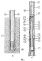
- the core barrel shown in Figs. 1A and 1B comprises an outer assembly formed of a plurality of outer tubes 1, 2 and 3 which are screwed to one another, and of a core bit 4. From the surface, this outer assembly is driven in rotation about the axis 5.
- the core barrel additionally comprises an inner assembly formed of a plurality of inner tubes 6, 7 and 8 which are screwed to one another, and of core removal elements 9 which are known and are shown schematically.
- a holder in the illustrated example two upstream and downstream roller bearings 10 and 11, are provided for holding the inner assembly in the outer assembly. In this way, these assemblies are reciprocally free in rotation, and the inner assembly remains fixed in rotation while the outer assembly turns about its axis. It would also be possible to provide more than two rolling bearings, or even just one, between the two assemblies.
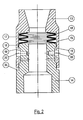
- the core barrel additionally comprises a spacer element 12 which is shown in detail in Fig. 2 .
- the spacer element 12 is housed inside the outer tube 1.
- it comprises an upstream tubular part 13 which bears against the outer tube 1 and a downstream tubular part 14 which bears against the upstream rolling bearing 10.
- the upstream tubular part 13 is provided with a female tubular end piece 15 while the downstream tubular part 14 has a male tubular end piece 16 which is capable of sliding axially inside the cavity 17 of the aforementioned female end piece.
- a spring member 18 formed of a plurality of stacked frustoconical spring washers is housed at the bottom of the cavity 17 of the upstream tubular part 13, bearing against the male tubular end piece 16 pushed into the female tubular end piece 15.
- Retaining features limit the possibilities of moving apart and, in the illustrated case, simultaneously of bringing together the upstream and downstream tubular parts 13 and 14.
- These retaining features consist here of a plurality of elongate slots 19 provided in the axial direction on the female tubular end piece 15, and of locking elements 20, in the form of bolts for example, which are screwed into the male tubular end piece 16 so as to protrude radially into the elongate slots 19.
- the ends of the elongate slots 19 serve as a stop for the locking elements 20 and thus limit a moving-apart of the two parts of the spacer element, beyond a predetermined value.
- a shoulder 35 is provided on the downstream tubular part 14 so as to prevent the parts 13 and 14 from being brought closer together beyond a certain limit.
- the holder for holding the inner assembly in the outer assembly advantageously comprise, as indicated above, two upstream and downstream rolling bearings 10 and 11 which are placed around the inner tube 6, in particular around the upstream end thereof, and are arranged inside the outer tube 1.
- the inner tube 6 carries close to its upstream end an annular flange 21 which protrudes radially therefrom. This flange is clamped between the two rolling bearings 10 and 11.
- the downstream rolling bearing 11 is housed between the downstream-facing annular bearing surface 22 of the flange 21 and an annular stop surface 23 of the outer tube 1.
- the upstream rolling bearing is arranged between the upstream-facing annular bearing surface 24 of the flange 21 and the spacer element 12, in particular the downstream tubular part 14 thereof.
- the spring member by exerting its spacing action between the upstream and downstream tubular parts 13 and 14 of the spacer element, has the effect of pushing in the downstream direction the two rolling bearings 10 and 11 and the flange clamped between them, the downstream rolling bearing 11 being retained by the annular stop surface 23 of the outer assembly.
- downstream rolling bearing 11 may no longer be in contact with the annular stop surface 23 or the annular bearing surface 22, or even risks being dislocated due to a disconnection of the elements constituting this downstream rolling bearing 11.
- the upstream rolling bearing 10 takes over while, in addition, the spring member tends to oppose this ascent.
- the outer tube 1 is composed of two downstream and upstream sections 25 and 25'. These two sections are joined to one another by a robust thread 26.
- the downstream section 25 has the upstream-facing annular stop surface 23.
- the core barrel comprises, in a known manner, a system for adjusting the depth position of the inner assembly relative to the outer assembly.
- the inner tube 6 is held by the rolling bearings 10 and 11 inside the outer assembly.
- it has an outer thread 27 capable of cooperating with an inner thread of the next inner tube 7.
- This arrangement makes it possible to fix the inner assembly at an adjustable depth relative to the outer assembly.
- the structure is therefore greatly simplified compared to the core barrels according to the known prior art, which minimises the possibilities for damage.
- the outer thread 27 is preferably specially designed to be on the one hand robust, so as to minimise the risks of wear on the thread, and on the other hand particularly long, so as to have an extended adjustment length for the inner assembly relative to the outer assembly.
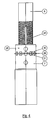
- a locking nut 28 which is screwed onto the inner tube 6, upstream of the inner tube 7. Once the position of the inner assembly relative to the outer assembly has been adjusted, it is then possible to screw the locking nut 28 against the inner tube 7 to a predetermined clamping torque. This nut substantially prevents any unscrewing of the inner tubes 6 and 7 associated with the vibrations, and thus reduces the causes of damage or breakage of the outer (adjustment) thread 27.
- a locking washer 29 which, in the position of use of the core barrel, is clamped between the locking nut 28 and the upstream end of the inner tube 7.
- This washer is preferably arranged so as to prevent any unscrewing of the locking nut 28 and of the inner tube 7.
- the locking nut 28 has peripheral notches 30 and the upstream end of the inner tube 7 has peripheral notches 31.
- the locking washer 29 has corresponding tabs 32 around its periphery. In the screwed position, some of the tabs can be folded in the upstream direction into the notches 30 and some can be folded in the downstream direction into the notches 31, thus preventing any separation movement between the locking nut 28 and the inner tube 7.
- a core barrel comprising an additional spacer element 36, as shown in Fig. 6 .
- the core barrel of Fig. 6 is identical to the core barrel of Figs. 1 to 5 , except in the respects illustrated in Fig. 6 and as described below.
- the embodiment of Fig. 6 has additional spacer element 36.
- the additional spacer element is a helical spring.
- the additional spacer element is to be inserted between the downstream rolling bearing 11 and the upstream-facing annular stop surface 23 of the outer tube 1.
- the spring is prestressed, which makes it possible to produce a vertical force, directed upwards, on the downstream rolling bearing 11 and to keep the elements of this rolling bearing 11 in compression, so that they remain secured.
- the downstream rolling bearing 11 is accompanied in this displacement and it is not subject to any impact upon once again making contact with the stop surface 23.
- the invention may find application in other drilling apparatus where it is desired to provide axial damping between relatively rotatable tubular members, and in cases where it is desirable to be able to securely adjust the length and/or relative position between threadedly connected tubular members, such as drill string components and related equipment, for example in a bottom hole assembly.
Landscapes
- Engineering & Computer Science (AREA)
- Life Sciences & Earth Sciences (AREA)
- Geology (AREA)
- Mining & Mineral Resources (AREA)
- Physics & Mathematics (AREA)
- Environmental & Geological Engineering (AREA)
- Fluid Mechanics (AREA)
- General Life Sciences & Earth Sciences (AREA)
- Geochemistry & Mineralogy (AREA)
- Mechanical Engineering (AREA)
- Earth Drilling (AREA)
- Rolling Contact Bearings (AREA)
Description
- The present invention relates to drilling apparatus. The invention may find particular application in a core barrel, in particular for use in the field of oil prospecting, comprising
- at least one outer tube and a core bit which form an outer assembly,
- at least one inner tube and core removal elements which form an inner assembly, and
- a holder for holding the inner assembly in the outer assembly which comprise at least one rolling bearing arranged between them so that these assemblies are reciprocally free in rotation.
- In a customary core barrel, the outer assembly is driven in rotation and the core bit can therefore dig a core hole. During this time, the inner assembly is held inside the outer assembly in a position fixed in terms of rotation, while being driven axially by the outer assembly.
- Core barrels may be made to pass through geological layers, thereby generating very high levels of vibration in the core drilling equipment. Often, the tools that exist on the market do not withstand these extreme conditions. This is because the axial vibrations increase the risks of jamming of the system for holding the inner assembly inside the outer assembly. They may also cause damage to the numerous threads which are usually used to join together the outer assembly and inner assembly. Finally, these axial vibrations often have the effect of modifying the axial position of the inner assembly relative to the outer assembly whereas, in order for the core to be removed correctly, it is desirable that the respective depth positions of the core bit and of the core removal elements are appropriately adjusted.
- It would be desirable to develop a core barrel in which these above-described vibrations which damage the threads are greatly reduced. It would also be desirable to considerably simplify the core drilling equipment and to reduce as far as possible the number of threads and also the number of parts. Finally, it would also be desirable to lock the system for adjusting the axial position of the inner assembly in the outer assembly, so as to prevent any disconnection between these once this position has been adjusted.
-
US-A-4930587 discloses a coring tool having a core cutting section and an actuating section. The core cutting section includes inner and outer barrels which are rotatable with respect to one another about a longitudinal axis of the tool. A bearing ring and contact ring are provided to allow such rotation. A spring is sandwiched between the contact ring and a radial shoulder to allow for tolerances in the moveable components and wearing of parts. - The present invention has been made in view of the foregoing background. A drilling apparatus according to a first aspect of the present invention is defined in
claim 1 below. - The spring member, which is preferably prestressed, has the effect, when axial vibrations of the inner assembly occur, of absorbing these vibrations and therefore filtering them.
- According to one embodiment of the invention, the spacer element comprises an upstream tubular part which bears against an aforementioned outer tube, and a downstream tubular part which bears against an aforementioned rolling bearing, said spring member being arranged between these upstream them apart, the spacer element additionally comprising retaining features which limit the moving-apart thereof.
- The terms upstream and downstream in the context of the present invention are to be understood as a function of the core drilling direction, an upstream position or element being closer to the surface and a downstream position or element being closer to the bottom of the core hole. The spring member advantageously consists of spring washers. The latter are preferably arranged so that all the spring washers exert an elastic stress both in the upstream direction and in the downstream direction. Other known spring member can of course be envisaged, for example a helical spring.
- According to one advantageous embodiment of the invention, one of said upstream and downstream tubular parts has a female tubular end piece and the other has a male tubular end piece capable of sliding axially inside a cavity of the female tubular end piece, and the spring member is housed at the bottom of said cavity, bearing against the male end piece pushed into the female end piece. The spacer element is in this way in an advantageously compact form.
- Said retaining features, which limit the moving-apart described above, advantageously comprise a plurality of elongate slots provided in the axial direction in the female tubular end piece and locking elements fixed to the male tubular end piece so as to protrude radially into said elongate slots and to lock a predetermined spacing of said tubular parts by bearing against one end of said elongate slots. This arrangement allows a particularly simple and robust installation of the spacer element.
- According to one particularly advantageous embodiment of the invention, said holder comprises two upstream and downstream rolling bearings placed around an aforementioned inner tube and housed inside an aforementioned outer tube, the downstream rolling bearing being arranged between a downstream-facing first annular bearing surface of the inner tube and an upstream-facing annular stop surface of the outer tube, whereas the upstream rolling bearing is arranged between an upstream-facing second annular bearing surface of the inner tube and said spacer element, said first and second annular bearing surfaces of the inner tube being located between the two rolling bearings.
- The particular arrangement of an inner tube biased axially in the downstream direction by a spring member and clamped between two rolling bearings makes it possible to eliminate almost all the threads which, in the prior art, were necessary to ensure the connection between the outer assembly and inner assembly. This results in an item of equipment which is particularly robust and resistant to vibrations. The inner tube remains in a very stable position, correctly aligned axially by the two rolling bearings.
- Advantageously, said first and second annular bearing surfaces of the aforementioned inner tube are provided on an annular flange which protrudes radially therefrom, and this annular flange is clamped between the upstream rolling bearing, spaced apart from the outer assembly under the spacing action of the spring member of the spacer element, and the downstream rolling bearing which is retained by the annular stop surface of the outer tube.
- According to one particular embodiment of the invention, the aforementioned outer tube is composed of two upstream and downstream sections which are screwed to one another, the spacer element bears between said upstream section and said upstream rolling bearing, and the downstream section has said annular stop surface on which the downstream rolling bearing bears. In this way, due to the clamping which results from screwing these two upstream and downstream sections together, the spring force of the spring member of the spacer element is automatically applied to the inner assembly at a specific value which can be predetermined.
- According to one embodiment of the invention, said inner tube of the inner assembly is held by said holder inside the outer assembly at an upstream end, and, at its downstream end, it has an outer thread capable of cooperating with an inner thread of another inner tube of the inner assembly in order to fix this inner assembly in an axially adjusted manner in a position of use.
- The inner assembly can thus be adjusted to a suitable depth relative to the outer assembly in order to remove the core, by using just one single connecting thread, which greatly reduces the risks of damage and jamming.
- Since unscrewing may occur under the effect of the vibrations, advantageously the core barrel additionally comprises a threaded locking nut, arranged on said outer thread of said downstream end of said inner tube, upstream of the other inner tube, and, in said position of use, this locking nut is clamped to a predetermined clamping torque against said other inner tube. Preferably, the core barrel additionally comprises a locking washer which, in said position of use, is clamped around said threaded downstream end of said inner tube, between a threaded locking nut and said other inner tube, this locking washer being arranged in such a way as to prevent any unscrewing of the nut and of said other inner tube on said threaded downstream end. Such a system, which is effective, safe, compact and easy to use, ensures that the clamping stress of the locking nut is maintained throughout the entire core drilling process. This stress is constant and permanent throughout the entire core drilling process. It therefore ensures the filtration of the cyclic stresses associated with the aforementioned axial vibrations, thereby considerably attenuating the risks of wear of the aforementioned connecting thread due to a mechanical fatigue phenomenon.
- Other details and particular features of the invention will emerge from the description of an exemplary embodiments of the invention, said description being given below by way of example only, with reference to the appended drawings, in which:-
-
Figs. 1A and 1B together show a view in axial section of an embodiment of a core barrel according to the invention; -
Fig. 2 shows a view in axial section of a spacer element used in the embodiment ofFigs. 1A and 1B ; -
Figs. 3 and4 show the installation of an embodiment of a system for adjusting the position of the inner assembly relative to the outer assembly of a core barrel according to the invention; -
Fig. 5 shows a plan view of a locking washer of the adjustment system ofFigs. 3 and4 ; and -
Fig. 6 shows a partial view in axial section of a variant embodiment of a spacer element as may be used in a core barrel according to the invention. - In the various figures, identical or analogous elements are denoted by the same references.
- The core barrel shown in
Figs. 1A and 1B comprises an outer assembly formed of a plurality ofouter tubes core bit 4. From the surface, this outer assembly is driven in rotation about theaxis 5. The core barrel additionally comprises an inner assembly formed of a plurality ofinner tubes core removal elements 9 which are known and are shown schematically. Finally, a holder, in the illustrated example two upstream anddownstream roller bearings - According to the example of embodiment shown in
Figs. 1A and 1B , the core barrel additionally comprises aspacer element 12 which is shown in detail inFig. 2 . - The
spacer element 12 is housed inside theouter tube 1. In the illustrated example, it comprises an upstreamtubular part 13 which bears against theouter tube 1 and a downstreamtubular part 14 which bears against the upstream rolling bearing 10. In this example, the upstreamtubular part 13 is provided with a femaletubular end piece 15 while the downstreamtubular part 14 has a maletubular end piece 16 which is capable of sliding axially inside thecavity 17 of the aforementioned female end piece. - In the illustrated example of embodiment, a
spring member 18 formed of a plurality of stacked frustoconical spring washers is housed at the bottom of thecavity 17 of the upstreamtubular part 13, bearing against the maletubular end piece 16 pushed into the femaletubular end piece 15. - Retaining features limit the possibilities of moving apart and, in the illustrated case, simultaneously of bringing together the upstream and downstream
tubular parts elongate slots 19 provided in the axial direction on the femaletubular end piece 15, and of lockingelements 20, in the form of bolts for example, which are screwed into the maletubular end piece 16 so as to protrude radially into theelongate slots 19. The ends of theelongate slots 19 serve as a stop for thelocking elements 20 and thus limit a moving-apart of the two parts of the spacer element, beyond a predetermined value. Ashoulder 35 is provided on the downstreamtubular part 14 so as to prevent theparts - By virtue of this arrangement, the axial vibrations which may occur as the core barrel passes through hard geological layers are effectively absorbed and damped by the spacer element.
- As can be seen from
Figs. 1A and 1B , the holder for holding the inner assembly in the outer assembly advantageously comprise, as indicated above, two upstream and downstream rollingbearings inner tube 6, in particular around the upstream end thereof, and are arranged inside theouter tube 1. - In this example of embodiment, the
inner tube 6 carries close to its upstream end anannular flange 21 which protrudes radially therefrom. This flange is clamped between the two rollingbearings annular bearing surface 22 of theflange 21 and anannular stop surface 23 of theouter tube 1. The upstream rolling bearing is arranged between the upstream-facingannular bearing surface 24 of theflange 21 and thespacer element 12, in particular the downstreamtubular part 14 thereof. The spring member, by exerting its spacing action between the upstream and downstreamtubular parts bearings bearing 11 being retained by theannular stop surface 23 of the outer assembly. - Thus, in the case where the inner assembly ascends towards the surface under the effect of axial vibrations, it can be imagined that the downstream rolling
bearing 11 may no longer be in contact with theannular stop surface 23 or theannular bearing surface 22, or even risks being dislocated due to a disconnection of the elements constituting this downstream rollingbearing 11. However, according to the invention, theupstream rolling bearing 10 takes over while, in addition, the spring member tends to oppose this ascent. - As can be seen from
Figs. 1A and 1B , in the illustrated example of embodiment, theouter tube 1 is composed of two downstream andupstream sections 25 and 25'. These two sections are joined to one another by arobust thread 26. Thedownstream section 25 has the upstream-facingannular stop surface 23. By a suitable screwing of these twosections 25 and 25', it is possible to adjust automatically the return force of thespring member 18 to an appropriate specific value. - In the example of embodiment shown in
Figs. 1A, 1B ,3 and4 , the core barrel comprises, in a known manner, a system for adjusting the depth position of the inner assembly relative to the outer assembly. At its upstream end, theinner tube 6 is held by the rollingbearings outer thread 27 capable of cooperating with an inner thread of the nextinner tube 7. This arrangement makes it possible to fix the inner assembly at an adjustable depth relative to the outer assembly. It should be noted that, in this embodiment, there is a single thread, theouter thread 27, for forming the connection between the outer assembly and the inner assembly, and for adjusting the position of use of the core barrel. The structure is therefore greatly simplified compared to the core barrels according to the known prior art, which minimises the possibilities for damage. - The
outer thread 27 is preferably specially designed to be on the one hand robust, so as to minimise the risks of wear on the thread, and on the other hand particularly long, so as to have an extended adjustment length for the inner assembly relative to the outer assembly. - In order to prevent any unscrewing from occurring on the adjustment system between the
inner tubes nut 28 which is screwed onto theinner tube 6, upstream of theinner tube 7. Once the position of the inner assembly relative to the outer assembly has been adjusted, it is then possible to screw the lockingnut 28 against theinner tube 7 to a predetermined clamping torque. This nut substantially prevents any unscrewing of theinner tubes thread 27. - Advantageously, as shown in detail in
Figs. 3 to 5 , it is possible to provide a lockingwasher 29 which, in the position of use of the core barrel, is clamped between the lockingnut 28 and the upstream end of theinner tube 7. This washer is preferably arranged so as to prevent any unscrewing of the lockingnut 28 and of theinner tube 7. In the illustrated example, the lockingnut 28 hasperipheral notches 30 and the upstream end of theinner tube 7 hasperipheral notches 31. The lockingwasher 29 has correspondingtabs 32 around its periphery. In the screwed position, some of the tabs can be folded in the upstream direction into thenotches 30 and some can be folded in the downstream direction into thenotches 31, thus preventing any separation movement between the lockingnut 28 and theinner tube 7. - In order that said washer is secured to the
inner tube 6 in the angular position while remaining free in terms of axial displacement, twoinner tabs 33 have been added to thewasher 29 so as to be housed in twoaxial recesses 34 provided for this purpose on theinner tube 6. As soon astabs 32 are engaged in theinner tube 7 and the lockingnut 28, theselatter elements inner tube 6. - It has also been found that, with a core barrel as designed according to the invention, it became possible to eliminate the seals which were usually required. Even the lubrication of the
outer adjustment thread 27 has in fact been found to be unnecessary, and therefore a lubrication chamber at this location has turned out to be superfluous. This therefore results in an increased reliability of the system, and it is thus possible to suppress the temperature limits for use of the core barrel in view of the omission of seals made from rubber or plastomer material. - It must be understood that the present invention is in no way limited to the embodiment described above and that many modifications can be made thereto within the scope of the appended claims.
- For example, according to one advantageous embodiment of the invention, there can be envisaged a core barrel comprising an
additional spacer element 36, as shown inFig. 6 . The core barrel ofFig. 6 is identical to the core barrel ofFigs. 1 to 5 , except in the respects illustrated inFig. 6 and as described below. - As stated, the embodiment of
Fig. 6 hasadditional spacer element 36. In this example of embodiment, the additional spacer element is a helical spring. The additional spacer element is to be inserted between the downstream rollingbearing 11 and the upstream-facingannular stop surface 23 of theouter tube 1. When the twosections 25 and 25' of theouter tube 1 are screwed together, the spring is prestressed, which makes it possible to produce a vertical force, directed upwards, on the downstream rollingbearing 11 and to keep the elements of this rollingbearing 11 in compression, so that they remain secured. In the event of upward axial displacement of the inner assembly, the downstream rollingbearing 11 is accompanied in this displacement and it is not subject to any impact upon once again making contact with thestop surface 23. - Although the above description has been made predominantly with respect to a core barrel, the invention may find application in other drilling apparatus where it is desired to provide axial damping between relatively rotatable tubular members, and in cases where it is desirable to be able to securely adjust the length and/or relative position between threadedly connected tubular members, such as drill string components and related equipment, for example in a bottom hole assembly.
Claims (13)
- A core barrel (1, 2, 3, 4, 6, 7, 8, 9) for use in the field of oil prospecting, the core barrel comprising:- a first tubular member (1, 2, 3) forming an outer assembly and including at least one outer tube (1, 2, 3);- a second tubular member (6, 7, 8, 9) forming an inner assembly and including at least one inner tube (6, 7, 8) and core removal elements (9), the second tubular member (6, 7, 8, 9) being mounted at least partly within the first tubular member (1, 2, 3) so as to be reciprocally free in rotation with respect to the first tubular member (1, 2, 3) about an axis (5);- a holder for holding the inner assembly in the outer assembly, the holder comprising at least one rolling bearing (10, 11) arranged between the inner assembly and the outer assembly so that these assemblies are reciprocally free in rotation;- at least one spacer element (12, 13, 14; 36) which is housed inside the outer assembly, bearing on the one hand against a bearing surface of one of the inner and outer assemblies and on the other hand against the rolling bearing (10, 11);- a restoring member (18) forming a part of at least one spacer element (12, 13, 14) and being operable for applying forces between the first tubular member (1, 2, 3) and the second tubular member (6, 7, 8, 9) at least in respective first axial directions in response to relative displacement of the first tubular member (1, 2, 3) and the second tubular member (6, 7, 8, 9) in the respective opposite axial directions; and- a core bit (4) operatively connected to one of the first or second tubular members (1, 2, 3, 6, 7, 8, 9) so as to be rotated together therewith, characterised in that the restoring member (18) being a spring member (18) that axially biases the rolling bearing (10, 11) away from the bearing surface;
and in that each spacer element (12, 13, 14) comprises an upstream tubular part (13) which bears against an outer tube (1, 2, 3), and a downstream tubular part (14) which bears against the rolling bearing (10, 11), the spring member (18) being arranged between the upstream tubular part (13) and the downstream tubular part (14) bearing against each of them and acting thereon axially so as to move them apart, the spacer element (12, 13, 14) additionally comprising retaining features (19, 20) which limit the moving apart of the upstream and downstream tubular parts (13, 14). - A core barrel according to claim 1, wherein the spring member (18) consists of spring washers.
- A core barrel according to claim 1 or 2, wherein one of the upstream and downstream tubular parts (13, 14) has a female tubular end piece (15) and the other part has a male tubular end piece (16) capable of sliding axially inside a cavity (17) of the female tubular end piece (15), the spring member (18) being housed at the bottom of the cavity (17) bearing against the male tubular end piece (16) pushed into the female tubular end piece (15).
- A core barrel according to claim 3, wherein the retaining features (19, 20) comprise a plurality of elongate slots (19) extending in the axial direction in the female tubular end piece (15) and locking elements (20) fixed to the male tubular end piece (16) so as to protrude radially into the elongate slots (19) and to limit spacing of the tubular parts (13, 14) by bearing against one end of the elongate slots (19).
- A core barrel according to any one of the preceding claims, wherein the holder comprises an upstream roller bearing (10) and a downstream rolling bearing (11) placed around one of the inner tubes (6) and housed inside one of the outer tubes (1), the downstream rolling bearing (11) being arranged between a downstream-facing first annular bearing surface (22) of the one inner tube (6) and an upstream-facing annular stop surface (23) of the outer tube (1), and the upstream rolling bearing (10) being arranged between an upstream-facing second annular bearing surface (24) of the inner tube (6) and the spacer element (12), the first and second annular bearing surfaces (22, 24) of the inner tube (6) being located between the two rolling bearings (10, 11).
- A core barrel according to claim 5, wherein the first and second annular bearing surfaces (22, 24) of the inner tube (6) are provided on an annular flange (21) which protrudes radially therefrom, the annular flange (21) being clamped between the upstream rolling bearing (10) and the downstream roller bearing (11), the upstream rolling bearing (10) being axially spaced apart from the outer assembly under the spacing action of the spring member (18) of the spacer element (12, 13, 14) and the downstream rolling bearing (11) being retained by the annular stop surface (23) of the outer tube (1).
- A core barrel according to claim 5 or 6, wherein the outer tube (1) comprises an upstream section (25') and a downstream section (25) which are screwed to one another, the spacer element (12) bearing between the upstream section (25') and the upstream rolling bearing (10), the downstream section (25) having the upstream-facing annular stop surface (23) on which the downstream rolling bearing (11) bears, the screwing of the upstream section (25') and the downstream section (25) preferably being adjustable to adjust a prestressed spring force of the spring element (18) of the spacer element (12, 13, 14).
- A core barrel according to any one of claims 5 to 7, further comprising an additional spacer element (36) inserted between the downstream rolling bearing (11) and the upstream-facing annular stop surface (23) of the outer tube (1).
- A core barrel according to claim 8, wherein the additional spacer element (36) is a spring member.
- A core barrel according to any one of claims 5 to 9 , wherein the inner tube (6) of the inner assembly is held by the holder inside the outer assembly at its upstream end, and, at its downstream end, the inner tube (6) has an outer thread (27) capable of cooperating with an inner thread of another inner tube (7) of the inner assembly in order to fix the inner assembly in an axially adjusted condition.
- A core barrel according to claim 10, further comprising a threaded locking nut (28) arranged on the outer thread (27) of the downstream end of the inner tube (6) which is held by the holder upstream of the other inner tube (7), the locking nut (28) being clamped against the other inner tube (7) when the inner assembly is in the axially adjusted condition.
- A core barrel according to claim 9, further comprising a locking washer (29) which, when the inner assembly is in the axially adjusted condition, is clamped around the threaded downstream end of the inner tube (6) between a threaded locking nut (28) and another inner tube (7), the locking washer being arranged in such a way as to prevent any unscrewing of the threaded locking nut (28) and of the other inner tube (7) on the threaded downstream end.
- Drilling apparatus including a core barrel according to any one of the preceding claims.
Applications Claiming Priority (2)
| Application Number | Priority Date | Filing Date | Title |
|---|---|---|---|
| US22394009P | 2009-07-08 | 2009-07-08 | |
| PCT/EP2010/059845 WO2011003990A2 (en) | 2009-07-08 | 2010-07-08 | Core barrel and related drilling apparatus and method |
Publications (2)
| Publication Number | Publication Date |
|---|---|
| EP2452038A2 EP2452038A2 (en) | 2012-05-16 |
| EP2452038B1 true EP2452038B1 (en) | 2013-08-21 |
Family
ID=43429601
Family Applications (1)
| Application Number | Title | Priority Date | Filing Date |
|---|---|---|---|
| EP10729905.9A Not-in-force EP2452038B1 (en) | 2009-07-08 | 2010-07-08 | Core barrel and related drilling apparatus and method |
Country Status (5)
| Country | Link |
|---|---|
| US (2) | US20120273279A1 (en) |
| EP (1) | EP2452038B1 (en) |
| CN (1) | CN102482925A (en) |
| CA (1) | CA2767487A1 (en) |
| WO (1) | WO2011003990A2 (en) |
Cited By (1)
| Publication number | Priority date | Publication date | Assignee | Title |
|---|---|---|---|---|
| CN108474241A (en) * | 2016-03-03 | 2018-08-31 | 哈利伯顿能源服务公司 | Inner cores cylinder for coring tool crimps connection |
Families Citing this family (9)
| Publication number | Priority date | Publication date | Assignee | Title |
|---|---|---|---|---|
| US9187958B2 (en) * | 2012-08-14 | 2015-11-17 | Chevron U.S.A. Inc. | Reamer with improved performance characteristics in hard and abrasive formations |
| CA3006180A1 (en) * | 2012-11-01 | 2014-05-08 | Longyear Tm, Inc. | Core barrel holder and methods of using same |
| US9869146B2 (en) * | 2013-04-17 | 2018-01-16 | Halliburton Energy Services, Inc. | Methods and apparatus for coring |
| US10378347B2 (en) | 2015-12-07 | 2019-08-13 | Schlumberger Technology Corporation | Sidewall core detection |
| CN107401386B (en) * | 2017-08-03 | 2024-06-21 | 中石化石油工程技术服务有限公司 | A short circuit to prevent vibration and blockage of oil drilling core |
| CN111236872B (en) * | 2020-01-17 | 2021-10-29 | 中煤科工集团西安研究院有限公司 | Directional rope core drill and drilling method thereof |
| JP7670949B2 (en) | 2020-09-11 | 2025-05-01 | ダイキン工業株式会社 | Refrigerant piping unit and refrigeration device |
| WO2022119455A1 (en) * | 2020-12-03 | 2022-06-09 | Coremax Limited | A core sample handling device |
| CN113982515B (en) * | 2021-10-28 | 2022-07-15 | 中国地质大学(北京) | Pressure-holding coring device |
Family Cites Families (14)
| Publication number | Priority date | Publication date | Assignee | Title |
|---|---|---|---|---|
| US1305009A (en) | 1919-05-27 | Lock-ntit eor couplings | ||
| US178245A (en) | 1876-06-06 | Improvement in pipe-couplings | ||
| US886083A (en) | 1908-01-28 | 1908-04-28 | Cyclone Drill Company | Discharge-stem. |
| FR539855A (en) * | 1921-05-14 | 1922-07-01 | Bolt system with non-removable nut or locknut | |
| US2128914A (en) * | 1936-02-04 | 1938-09-06 | Cameron Iron Works Inc | Core barrel mounting |
| US2403002A (en) * | 1940-03-06 | 1946-07-02 | Henry L Johnson | Apparatus for undisturbed overburden sampling |
| US3012622A (en) * | 1959-04-20 | 1961-12-12 | Christensen Diamond Prod Co | Core barrel apparatus |
| US3294141A (en) * | 1965-10-20 | 1966-12-27 | Eugene B Schotthoefer | Shaft mounting adjustment nut means |
| WO1985003326A1 (en) * | 1984-01-23 | 1985-08-01 | Teleco-Magna Inc. | Downhole motor and bearing assembly |
| US4930587A (en) * | 1989-04-25 | 1990-06-05 | Diamant Boart-Stratabit (Usa) Inc. | Coring tool |
| US5074681A (en) * | 1991-01-15 | 1991-12-24 | Teleco Oilfield Services Inc. | Downhole motor and bearing assembly |
| CN100408804C (en) * | 2002-12-12 | 2008-08-06 | 国际壳牌研究有限公司 | Systems for axially joining pipe ends and mandrels and connecting assemblies for axially joining two pipe ends |
| US6976816B2 (en) * | 2003-08-01 | 2005-12-20 | Dana Corporation | Combination lock washer and spindle bearing assembly |
| US7445251B2 (en) * | 2004-08-06 | 2008-11-04 | Illinois Tool Works Inc. | Two-piece oil filter oil cooler connector bolt |
-
2010
- 2010-07-08 EP EP10729905.9A patent/EP2452038B1/en not_active Not-in-force
- 2010-07-08 WO PCT/EP2010/059845 patent/WO2011003990A2/en not_active Ceased
- 2010-07-08 CN CN201080038771XA patent/CN102482925A/en active Pending
- 2010-07-08 US US13/382,753 patent/US20120273279A1/en not_active Abandoned
- 2010-07-08 CA CA2767487A patent/CA2767487A1/en not_active Abandoned
-
2015
- 2015-02-20 US US14/627,558 patent/US9885215B2/en active Active
Cited By (1)
| Publication number | Priority date | Publication date | Assignee | Title |
|---|---|---|---|---|
| CN108474241A (en) * | 2016-03-03 | 2018-08-31 | 哈利伯顿能源服务公司 | Inner cores cylinder for coring tool crimps connection |
Also Published As
| Publication number | Publication date |
|---|---|
| US20150226016A1 (en) | 2015-08-13 |
| CN102482925A (en) | 2012-05-30 |
| US9885215B2 (en) | 2018-02-06 |
| WO2011003990A2 (en) | 2011-01-13 |
| WO2011003990A3 (en) | 2011-08-25 |
| US20120273279A1 (en) | 2012-11-01 |
| CA2767487A1 (en) | 2011-01-13 |
| EP2452038A2 (en) | 2012-05-16 |
Similar Documents
| Publication | Publication Date | Title |
|---|---|---|
| US9885215B2 (en) | Core barrel and related drilling apparatus and method | |
| DE69108191T2 (en) | Hydraulic shock absorber for use in the borehole. | |
| US20170009532A1 (en) | Perforating Gun Connectors | |
| US9988859B2 (en) | Impact dampening apparatus | |
| EP2837840A1 (en) | Shaft coupling assembly and method for coupling shafts | |
| US20140105704A1 (en) | Antitheft Locking Device | |
| EP1991396B1 (en) | Device and method for loosening a sticking connection | |
| EP2169685B1 (en) | Connecting device for connecting a guide tube to a lower end nozzle in a nuclear fuel assembly | |
| US5092402A (en) | Tubing end locator | |
| EP2857129A1 (en) | Tool holder with a collet chuck for clamping a tool | |
| DE102017116617B4 (en) | Collet chucks | |
| CA2795669C (en) | Adjustable die | |
| CN108825227B (en) | Cutting device of heading machine and heading machine | |
| US4889198A (en) | Drilling jar latch | |
| US20150151414A1 (en) | Hand-driven mechanical screwdriver | |
| US5509475A (en) | Downhole stress absorber | |
| CN210317198U (en) | Thread protecting assembly for drill rod sleeve | |
| CN205325624U (en) | Electric tool | |
| WO2004050440A1 (en) | Window-wiping device, particularly for a motor vehicle | |
| WO2017106908A1 (en) | Liner bolt assembly and liner securing system | |
| CN204357910U (en) | Dismountable safety protection connects facility | |
| EP3263950B1 (en) | Centralizing bushing assembly | |
| DE102014102705B4 (en) | Clamping nut | |
| CN211287532U (en) | Shock attenuation formula impacter | |
| CN204300203U (en) | Pressure mounting of the spring assembly and use the spring assembly of this press-loading apparatus |
Legal Events
| Date | Code | Title | Description |
|---|---|---|---|
| PUAI | Public reference made under article 153(3) epc to a published international application that has entered the european phase |
Free format text: ORIGINAL CODE: 0009012 |
|
| 17P | Request for examination filed |
Effective date: 20120208 |
|
| AK | Designated contracting states |
Kind code of ref document: A2 Designated state(s): AL AT BE BG CH CY CZ DE DK EE ES FI FR GB GR HR HU IE IS IT LI LT LU LV MC MK MT NL NO PL PT RO SE SI SK SM TR |
|
| DAX | Request for extension of the european patent (deleted) | ||
| RIN1 | Information on inventor provided before grant (corrected) |
Inventor name: MAGEREN, OLIVIER Inventor name: FANNES, ERIC Inventor name: DELMAR, LUDOVIC |
|
| GRAP | Despatch of communication of intention to grant a patent |
Free format text: ORIGINAL CODE: EPIDOSNIGR1 |
|
| RIN1 | Information on inventor provided before grant (corrected) |
Inventor name: DELMAR, LUDOVIC Inventor name: FANNES, ERIC Inventor name: MAGEREN, OLIVIER |
|
| RAP1 | Party data changed (applicant data changed or rights of an application transferred) |
Owner name: HALLIBURTON ENERGY SERVICES, INC. |
|
| GRAS | Grant fee paid |
Free format text: ORIGINAL CODE: EPIDOSNIGR3 |
|
| GRAA | (expected) grant |
Free format text: ORIGINAL CODE: 0009210 |
|
| AK | Designated contracting states |
Kind code of ref document: B1 Designated state(s): AL AT BE BG CH CY CZ DE DK EE ES FI FR GB GR HR HU IE IS IT LI LT LU LV MC MK MT NL NO PL PT RO SE SI SK SM TR |
|
| REG | Reference to a national code |
Ref country code: GB Ref legal event code: FG4D |
|
| REG | Reference to a national code |
Ref country code: CH Ref legal event code: EP |
|
| REG | Reference to a national code |
Ref country code: AT Ref legal event code: REF Ref document number: 628233 Country of ref document: AT Kind code of ref document: T Effective date: 20130915 |
|
| REG | Reference to a national code |
Ref country code: IE Ref legal event code: FG4D |
|
| REG | Reference to a national code |
Ref country code: DE Ref legal event code: R096 Ref document number: 602010009661 Country of ref document: DE Effective date: 20131017 |
|
| REG | Reference to a national code |
Ref country code: NO Ref legal event code: T2 Effective date: 20130821 |
|
| REG | Reference to a national code |
Ref country code: NL Ref legal event code: VDEP Effective date: 20130821 Ref country code: AT Ref legal event code: MK05 Ref document number: 628233 Country of ref document: AT Kind code of ref document: T Effective date: 20130821 |
|
| REG | Reference to a national code |
Ref country code: LT Ref legal event code: MG4D |
|
| PG25 | Lapsed in a contracting state [announced via postgrant information from national office to epo] |
Ref country code: IS Free format text: LAPSE BECAUSE OF FAILURE TO SUBMIT A TRANSLATION OF THE DESCRIPTION OR TO PAY THE FEE WITHIN THE PRESCRIBED TIME-LIMIT Effective date: 20131221 Ref country code: AT Free format text: LAPSE BECAUSE OF FAILURE TO SUBMIT A TRANSLATION OF THE DESCRIPTION OR TO PAY THE FEE WITHIN THE PRESCRIBED TIME-LIMIT Effective date: 20130821 Ref country code: PT Free format text: LAPSE BECAUSE OF FAILURE TO SUBMIT A TRANSLATION OF THE DESCRIPTION OR TO PAY THE FEE WITHIN THE PRESCRIBED TIME-LIMIT Effective date: 20131223 Ref country code: SE Free format text: LAPSE BECAUSE OF FAILURE TO SUBMIT A TRANSLATION OF THE DESCRIPTION OR TO PAY THE FEE WITHIN THE PRESCRIBED TIME-LIMIT Effective date: 20130821 Ref country code: HR Free format text: LAPSE BECAUSE OF FAILURE TO SUBMIT A TRANSLATION OF THE DESCRIPTION OR TO PAY THE FEE WITHIN THE PRESCRIBED TIME-LIMIT Effective date: 20130821 Ref country code: LT Free format text: LAPSE BECAUSE OF FAILURE TO SUBMIT A TRANSLATION OF THE DESCRIPTION OR TO PAY THE FEE WITHIN THE PRESCRIBED TIME-LIMIT Effective date: 20130821 Ref country code: CY Free format text: LAPSE BECAUSE OF FAILURE TO SUBMIT A TRANSLATION OF THE DESCRIPTION OR TO PAY THE FEE WITHIN THE PRESCRIBED TIME-LIMIT Effective date: 20130821 |
|
| PG25 | Lapsed in a contracting state [announced via postgrant information from national office to epo] |
Ref country code: FI Free format text: LAPSE BECAUSE OF FAILURE TO SUBMIT A TRANSLATION OF THE DESCRIPTION OR TO PAY THE FEE WITHIN THE PRESCRIBED TIME-LIMIT Effective date: 20130821 Ref country code: GR Free format text: LAPSE BECAUSE OF FAILURE TO SUBMIT A TRANSLATION OF THE DESCRIPTION OR TO PAY THE FEE WITHIN THE PRESCRIBED TIME-LIMIT Effective date: 20131122 Ref country code: SI Free format text: LAPSE BECAUSE OF FAILURE TO SUBMIT A TRANSLATION OF THE DESCRIPTION OR TO PAY THE FEE WITHIN THE PRESCRIBED TIME-LIMIT Effective date: 20130821 Ref country code: BE Free format text: LAPSE BECAUSE OF FAILURE TO SUBMIT A TRANSLATION OF THE DESCRIPTION OR TO PAY THE FEE WITHIN THE PRESCRIBED TIME-LIMIT Effective date: 20130821 Ref country code: PL Free format text: LAPSE BECAUSE OF FAILURE TO SUBMIT A TRANSLATION OF THE DESCRIPTION OR TO PAY THE FEE WITHIN THE PRESCRIBED TIME-LIMIT Effective date: 20130821 Ref country code: LV Free format text: LAPSE BECAUSE OF FAILURE TO SUBMIT A TRANSLATION OF THE DESCRIPTION OR TO PAY THE FEE WITHIN THE PRESCRIBED TIME-LIMIT Effective date: 20130821 |
|
| PG25 | Lapsed in a contracting state [announced via postgrant information from national office to epo] |
Ref country code: EE Free format text: LAPSE BECAUSE OF FAILURE TO SUBMIT A TRANSLATION OF THE DESCRIPTION OR TO PAY THE FEE WITHIN THE PRESCRIBED TIME-LIMIT Effective date: 20130821 Ref country code: SK Free format text: LAPSE BECAUSE OF FAILURE TO SUBMIT A TRANSLATION OF THE DESCRIPTION OR TO PAY THE FEE WITHIN THE PRESCRIBED TIME-LIMIT Effective date: 20130821 Ref country code: NL Free format text: LAPSE BECAUSE OF FAILURE TO SUBMIT A TRANSLATION OF THE DESCRIPTION OR TO PAY THE FEE WITHIN THE PRESCRIBED TIME-LIMIT Effective date: 20130821 Ref country code: DK Free format text: LAPSE BECAUSE OF FAILURE TO SUBMIT A TRANSLATION OF THE DESCRIPTION OR TO PAY THE FEE WITHIN THE PRESCRIBED TIME-LIMIT Effective date: 20130821 Ref country code: CZ Free format text: LAPSE BECAUSE OF FAILURE TO SUBMIT A TRANSLATION OF THE DESCRIPTION OR TO PAY THE FEE WITHIN THE PRESCRIBED TIME-LIMIT Effective date: 20130821 Ref country code: RO Free format text: LAPSE BECAUSE OF FAILURE TO SUBMIT A TRANSLATION OF THE DESCRIPTION OR TO PAY THE FEE WITHIN THE PRESCRIBED TIME-LIMIT Effective date: 20130821 |
|
| PG25 | Lapsed in a contracting state [announced via postgrant information from national office to epo] |
Ref country code: IT Free format text: LAPSE BECAUSE OF FAILURE TO SUBMIT A TRANSLATION OF THE DESCRIPTION OR TO PAY THE FEE WITHIN THE PRESCRIBED TIME-LIMIT Effective date: 20130821 Ref country code: ES Free format text: LAPSE BECAUSE OF FAILURE TO SUBMIT A TRANSLATION OF THE DESCRIPTION OR TO PAY THE FEE WITHIN THE PRESCRIBED TIME-LIMIT Effective date: 20130821 |
|
| PLBE | No opposition filed within time limit |
Free format text: ORIGINAL CODE: 0009261 |
|
| STAA | Information on the status of an ep patent application or granted ep patent |
Free format text: STATUS: NO OPPOSITION FILED WITHIN TIME LIMIT |
|
| 26N | No opposition filed |
Effective date: 20140522 |
|
| PGFP | Annual fee paid to national office [announced via postgrant information from national office to epo] |
Ref country code: GB Payment date: 20140624 Year of fee payment: 5 |
|
| PGFP | Annual fee paid to national office [announced via postgrant information from national office to epo] |
Ref country code: NO Payment date: 20140624 Year of fee payment: 5 |
|
| REG | Reference to a national code |
Ref country code: DE Ref legal event code: R097 Ref document number: 602010009661 Country of ref document: DE Effective date: 20140522 |
|
| PGFP | Annual fee paid to national office [announced via postgrant information from national office to epo] |
Ref country code: DE Payment date: 20140731 Year of fee payment: 5 |
|
| PGFP | Annual fee paid to national office [announced via postgrant information from national office to epo] |
Ref country code: FR Payment date: 20140624 Year of fee payment: 5 |
|
| PG25 | Lapsed in a contracting state [announced via postgrant information from national office to epo] |
Ref country code: LU Free format text: LAPSE BECAUSE OF FAILURE TO SUBMIT A TRANSLATION OF THE DESCRIPTION OR TO PAY THE FEE WITHIN THE PRESCRIBED TIME-LIMIT Effective date: 20140708 |
|
| REG | Reference to a national code |
Ref country code: CH Ref legal event code: PL |
|
| REG | Reference to a national code |
Ref country code: IE Ref legal event code: MM4A |
|
| PG25 | Lapsed in a contracting state [announced via postgrant information from national office to epo] |
Ref country code: CH Free format text: LAPSE BECAUSE OF NON-PAYMENT OF DUE FEES Effective date: 20140731 Ref country code: LI Free format text: LAPSE BECAUSE OF NON-PAYMENT OF DUE FEES Effective date: 20140731 |
|
| PG25 | Lapsed in a contracting state [announced via postgrant information from national office to epo] |
Ref country code: IE Free format text: LAPSE BECAUSE OF NON-PAYMENT OF DUE FEES Effective date: 20140708 |
|
| REG | Reference to a national code |
Ref country code: DE Ref legal event code: R119 Ref document number: 602010009661 Country of ref document: DE |
|
| REG | Reference to a national code |
Ref country code: NO Ref legal event code: MMEP |
|
| GBPC | Gb: european patent ceased through non-payment of renewal fee |
Effective date: 20150708 |
|
| PG25 | Lapsed in a contracting state [announced via postgrant information from national office to epo] |
Ref country code: NO Free format text: LAPSE BECAUSE OF NON-PAYMENT OF DUE FEES Effective date: 20150731 Ref country code: MC Free format text: LAPSE BECAUSE OF FAILURE TO SUBMIT A TRANSLATION OF THE DESCRIPTION OR TO PAY THE FEE WITHIN THE PRESCRIBED TIME-LIMIT Effective date: 20130821 Ref country code: GB Free format text: LAPSE BECAUSE OF NON-PAYMENT OF DUE FEES Effective date: 20150708 Ref country code: DE Free format text: LAPSE BECAUSE OF NON-PAYMENT OF DUE FEES Effective date: 20160202 Ref country code: SM Free format text: LAPSE BECAUSE OF FAILURE TO SUBMIT A TRANSLATION OF THE DESCRIPTION OR TO PAY THE FEE WITHIN THE PRESCRIBED TIME-LIMIT Effective date: 20130821 |
|
| REG | Reference to a national code |
Ref country code: FR Ref legal event code: ST Effective date: 20160331 |
|
| PG25 | Lapsed in a contracting state [announced via postgrant information from national office to epo] |
Ref country code: FR Free format text: LAPSE BECAUSE OF NON-PAYMENT OF DUE FEES Effective date: 20150731 |
|
| PG25 | Lapsed in a contracting state [announced via postgrant information from national office to epo] |
Ref country code: BG Free format text: LAPSE BECAUSE OF FAILURE TO SUBMIT A TRANSLATION OF THE DESCRIPTION OR TO PAY THE FEE WITHIN THE PRESCRIBED TIME-LIMIT Effective date: 20130821 Ref country code: MT Free format text: LAPSE BECAUSE OF FAILURE TO SUBMIT A TRANSLATION OF THE DESCRIPTION OR TO PAY THE FEE WITHIN THE PRESCRIBED TIME-LIMIT Effective date: 20130821 |
|
| PG25 | Lapsed in a contracting state [announced via postgrant information from national office to epo] |
Ref country code: TR Free format text: LAPSE BECAUSE OF FAILURE TO SUBMIT A TRANSLATION OF THE DESCRIPTION OR TO PAY THE FEE WITHIN THE PRESCRIBED TIME-LIMIT Effective date: 20130821 Ref country code: HU Free format text: LAPSE BECAUSE OF FAILURE TO SUBMIT A TRANSLATION OF THE DESCRIPTION OR TO PAY THE FEE WITHIN THE PRESCRIBED TIME-LIMIT; INVALID AB INITIO Effective date: 20100708 |
|
| PG25 | Lapsed in a contracting state [announced via postgrant information from national office to epo] |
Ref country code: MK Free format text: LAPSE BECAUSE OF FAILURE TO SUBMIT A TRANSLATION OF THE DESCRIPTION OR TO PAY THE FEE WITHIN THE PRESCRIBED TIME-LIMIT Effective date: 20130821 |
|
| PG25 | Lapsed in a contracting state [announced via postgrant information from national office to epo] |
Ref country code: AL Free format text: LAPSE BECAUSE OF FAILURE TO SUBMIT A TRANSLATION OF THE DESCRIPTION OR TO PAY THE FEE WITHIN THE PRESCRIBED TIME-LIMIT Effective date: 20130821 |