EP2451703B1 - Stringer - Google Patents
Stringer Download PDFInfo
- Publication number
- EP2451703B1 EP2451703B1 EP10731504.6A EP10731504A EP2451703B1 EP 2451703 B1 EP2451703 B1 EP 2451703B1 EP 10731504 A EP10731504 A EP 10731504A EP 2451703 B1 EP2451703 B1 EP 2451703B1
- Authority
- EP
- European Patent Office
- Prior art keywords
- stringer
- plies
- stack
- termination
- taper
- Prior art date
- Legal status (The legal status is an assumption and is not a legal conclusion. Google has not performed a legal analysis and makes no representation as to the accuracy of the status listed.)
- Active
Links
Images







Classifications
-
- B—PERFORMING OPERATIONS; TRANSPORTING
- B29—WORKING OF PLASTICS; WORKING OF SUBSTANCES IN A PLASTIC STATE IN GENERAL
- B29C—SHAPING OR JOINING OF PLASTICS; SHAPING OF MATERIAL IN A PLASTIC STATE, NOT OTHERWISE PROVIDED FOR; AFTER-TREATMENT OF THE SHAPED PRODUCTS, e.g. REPAIRING
- B29C70/00—Shaping composites, i.e. plastics material comprising reinforcements, fillers or preformed parts, e.g. inserts
- B29C70/04—Shaping composites, i.e. plastics material comprising reinforcements, fillers or preformed parts, e.g. inserts comprising reinforcements only, e.g. self-reinforcing plastics
- B29C70/28—Shaping operations therefor
- B29C70/30—Shaping by lay-up, i.e. applying fibres, tape or broadsheet on a mould, former or core; Shaping by spray-up, i.e. spraying of fibres on a mould, former or core
-
- B—PERFORMING OPERATIONS; TRANSPORTING
- B29—WORKING OF PLASTICS; WORKING OF SUBSTANCES IN A PLASTIC STATE IN GENERAL
- B29C—SHAPING OR JOINING OF PLASTICS; SHAPING OF MATERIAL IN A PLASTIC STATE, NOT OTHERWISE PROVIDED FOR; AFTER-TREATMENT OF THE SHAPED PRODUCTS, e.g. REPAIRING
- B29C70/00—Shaping composites, i.e. plastics material comprising reinforcements, fillers or preformed parts, e.g. inserts
- B29C70/04—Shaping composites, i.e. plastics material comprising reinforcements, fillers or preformed parts, e.g. inserts comprising reinforcements only, e.g. self-reinforcing plastics
- B29C70/28—Shaping operations therefor
- B29C70/30—Shaping by lay-up, i.e. applying fibres, tape or broadsheet on a mould, former or core; Shaping by spray-up, i.e. spraying of fibres on a mould, former or core
- B29C70/302—Details of the edges of fibre composites, e.g. edge finishing or means to avoid delamination
-
- B—PERFORMING OPERATIONS; TRANSPORTING
- B29—WORKING OF PLASTICS; WORKING OF SUBSTANCES IN A PLASTIC STATE IN GENERAL
- B29D—PRODUCING PARTICULAR ARTICLES FROM PLASTICS OR FROM SUBSTANCES IN A PLASTIC STATE
- B29D99/00—Subject matter not provided for in other groups of this subclass
- B29D99/001—Producing wall or panel-like structures, e.g. for hulls, fuselages, or buildings
- B29D99/0014—Producing wall or panel-like structures, e.g. for hulls, fuselages, or buildings provided with ridges or ribs, e.g. joined ribs
-
- B—PERFORMING OPERATIONS; TRANSPORTING
- B64—AIRCRAFT; AVIATION; COSMONAUTICS
- B64C—AEROPLANES; HELICOPTERS
- B64C1/00—Fuselages; Constructional features common to fuselages, wings, stabilising surfaces or the like
- B64C1/06—Frames; Stringers; Longerons ; Fuselage sections
- B64C1/064—Stringers; Longerons
-
- Y—GENERAL TAGGING OF NEW TECHNOLOGICAL DEVELOPMENTS; GENERAL TAGGING OF CROSS-SECTIONAL TECHNOLOGIES SPANNING OVER SEVERAL SECTIONS OF THE IPC; TECHNICAL SUBJECTS COVERED BY FORMER USPC CROSS-REFERENCE ART COLLECTIONS [XRACs] AND DIGESTS
- Y02—TECHNOLOGIES OR APPLICATIONS FOR MITIGATION OR ADAPTATION AGAINST CLIMATE CHANGE
- Y02T—CLIMATE CHANGE MITIGATION TECHNOLOGIES RELATED TO TRANSPORTATION
- Y02T50/00—Aeronautics or air transport
- Y02T50/40—Weight reduction
-
- Y—GENERAL TAGGING OF NEW TECHNOLOGICAL DEVELOPMENTS; GENERAL TAGGING OF CROSS-SECTIONAL TECHNOLOGIES SPANNING OVER SEVERAL SECTIONS OF THE IPC; TECHNICAL SUBJECTS COVERED BY FORMER USPC CROSS-REFERENCE ART COLLECTIONS [XRACs] AND DIGESTS
- Y10—TECHNICAL SUBJECTS COVERED BY FORMER USPC
- Y10T—TECHNICAL SUBJECTS COVERED BY FORMER US CLASSIFICATION
- Y10T156/00—Adhesive bonding and miscellaneous chemical manufacture
- Y10T156/10—Methods of surface bonding and/or assembly therefor
- Y10T156/1052—Methods of surface bonding and/or assembly therefor with cutting, punching, tearing or severing
- Y10T156/1062—Prior to assembly
-
- Y—GENERAL TAGGING OF NEW TECHNOLOGICAL DEVELOPMENTS; GENERAL TAGGING OF CROSS-SECTIONAL TECHNOLOGIES SPANNING OVER SEVERAL SECTIONS OF THE IPC; TECHNICAL SUBJECTS COVERED BY FORMER USPC CROSS-REFERENCE ART COLLECTIONS [XRACs] AND DIGESTS
- Y10—TECHNICAL SUBJECTS COVERED BY FORMER USPC
- Y10T—TECHNICAL SUBJECTS COVERED BY FORMER US CLASSIFICATION
- Y10T428/00—Stock material or miscellaneous articles
- Y10T428/24—Structurally defined web or sheet [e.g., overall dimension, etc.]
- Y10T428/24479—Structurally defined web or sheet [e.g., overall dimension, etc.] including variation in thickness
Definitions
- the present invention relates to a laminated composite stringer having a taper at its termination, and to a method of forming such a stringer.
- a panel such as the skin of an aircraft wing or fuselage, may be reinforced by a series of elongate stringers which run along the length of the panel.
- the stringer typically comprises a web extending at right angles to the panel, and a flange engaging the panel.
- Stiffeners have to be terminated in certain areas due to obstructions so that the panel/stringer structure assumes a flat plate geometry.
- stiffeners In the case of an aircraft, stiffeners have to be terminated at, e.g. the wing tips, access holes, etc.
- stress supported by the stringer is transferred into the panel. Stringer terminations therefore cause areas of local stress concentration and the panel and stringer have a tendency to separate in these areas.
- the stringer flange may have a widened portion near the termination, a so-called "stringer foot”. This may be bolted or otherwise affixed to the panel. Alternatively, or additionally, a finger plate or cover plate may be provided over the stringer foot and bolted to the panel. These measures aid in dispersing the stringer load into the panel but high stress concentrations remain.
- the web typically has a taper of reducing height (perpendicular to the panel) near the termination in order to facilitate load transfer from the skin to the stringer, by providing a gradual increase in transverse bending and axial stiffness and relieving local stress concentrations.
- WO2008/132498A describes a stringer wherein the web has a taper of reducing height near the termination.
- EP1566334A describes a stringer wherein the web has two tapered regions of reducing height near the termination separated by a plateau.
- Another example of prior art is provided by US4606961A .
- a first aspect of the invention provides a laminated composite stringer having a termination at one end in its longitudinal direction, and including a laminated stack of composite structural plies, the stringer having a taper of reducing stack thickness at the stringer termination provided by consecutively terminating the internal plies in the stack towards the stringer termination.
- a second aspect of the invention provides a composite structure comprising a panel and the stringer of the first aspect bonded to the panel.
- a third aspect of the invention provides an aircraft comprising the composite structure according to the second aspect.
- a fourth aspect of the invention provides a method of manufacturing a laminated composite stringer having a termination at one end in its longitudinal direction, and including a laminated stack of composite structural plies, the stringer having a taper of reducing stack thickness at the stringer termination provided by consecutively terminating the internal plies in the stack towards the stringer termination, the method comprising: cutting the composite structural plies to a desired termination profile; and stacking the composite structural plies.
- the load transition is controlled and evenly distributed in a free-flow form instead of having to manage local stress concentrations.
- the load transition is such that no additional finger plate or cover plies are required, and the size and number of any bolts can be kept to a minimum.
- the termination design inhibits crack initiation and improves fracture mechanics.
- the stringer may have a flange for engaging a panel, and the stack taper may be in the flange.
- the stack taper in the flange may be in the longitudinal and/or transverse direction. Stress concentrations are most effectively reduced where the flange is tapered in both the longitudinal and transverse directions.
- the stringer may have an upstanding web, and the stack taper may be in the web.
- the web is preferably bifurcated at the termination, and a non-structural filler element may be disposed between "branches" of the bifurcated web.
- the flange and web of the stringer may be formed by joining a pair of substantially L-shaped stacks of laminated composite structural plies back-to-back. Due to the limitation of the minimum radius of the composite ply at the corner, a cleft may be formed between the L-shaped stacks, which can be filled with a non-structural filler element.
- the stringer may also be tapered such that the height of the web, and/or the width of the flange may be tapered at the termination.
- the width of the flange immediately inboard of the termination may be greater than the width of the flange further inboard of the termination.
- the plies may be cut by, for example, a laser or a water jet. Preferably, each ply is cut as soon as it is added to the stack of plies.
- An automatic tape laying machine may also be used to cut and lay each ply to form the stack.
- the plies may be laid such that the first ply is the largest and further, smaller plies are laid on top such that the upper plies terminate before the lower plies to form the taper of reducing stack thickness at the termination.
- the edges of the internal plies will be exposed as the uppermost ply, laid last, will be the smallest.
- a ply covering may be provided over the ply stack. Protecting the ply edges will improve peel resistance.
- the first ply may be the smallest and further, larger plies may be laid on top such that the lower plies terminate before the upper plies to form the taper of reducing stack thickness at the termination.
- the upper plies of this reverse lay-up will protect the edges of the lower plies and the uppermost ply will form a continuous surface.
- the lowermost ply lies closest to the panel when the stringer is bonded, or otherwise fixed, to the panel.
- the uppermost ply lies farthest from the panel.
- the plies are preferably fibre reinforced laminates pre-impregnated with resin, so called "pre-pregs".
- the plies may be dry fibre laminates and resin would need to be infused into the laminates after they have been cut and stacked.
- the resin may need to be cured in either case, for example in an autoclave.
- the fibres may be of carbon, glass, or other suitable materials.
- the resin is preferably epoxy.
- the stringer 100 includes a flange 101 having a width W and an upstanding web 102 having a height H. Note that only one end of the stringer is shown in Figure 1 .
- the stringer 100 has a termination 103 at one end. Inboard of the termination, the stringer 100 has substantially constant section (not shown in Figure 1 ). Adjacent to the termination 103, the flange 101 has a region of increased width W' so as to form a stringer foot 104.
- the stringer 100 is formed from a pair of back-to-back L-shaped stacks of composite laminate plies 105.
- the plies 105 are arranged such that the lowermost ply 105a is the largest ply and the uppermost ply 105b is the smallest ply.
- the plies are cut such that the lowermost ply 105a terminates at the stringer termination 103, and the uppermost ply 105b terminates a significant distance inboard of the termination 103.
- the remaining plies 105 intermediate the plies 105a and 105b are cut consecutively so as to form a taper, or ramp, of decreasing ply stack thickness towards the termination 103.
- the taper of decreasing ply stack thickness in the flange 101 is in both the longitudinal direction X and the transverse direction Y.
- the taper of reducing stack thickness in the flange 101 is also in the vertical direction Z.
- the taper of reducing stack thickness in the web 102 is in the transverse direction Y.
- the width W of the flange 101 also tapers, as does the height H of the upstanding web.
- the taper 106 in the width W of the flange 101 is set at approximately 45° to the longitudinal direction X.
- a second tapered region set at around 5° to the longitudinal direction X helps to blend between the taper 106 and the constant width section W' of the stringer foot 104.
- the taper 107 in the height H of the web 102 is set at approximately 30° to the horizontal.
- the stack of plies 105 is cut such that only the lowermost ply 105a remains at the termination 103.
- the exposed edges of the cut plies 105 in the tapers of reducing stack thickness in the flange 101 and web 102 can be susceptible to delamination. This can be overcome by providing a cover ply 105c over the uppermost ply 105b.
- the cover ply 105c is dimensioned so as to be at least as large as the lowermost ply 105a such that the cover ply 105c covers all of the other plies 105.
- the cover ply 105c further includes edge portions 108 which extend beyond the lowermost ply 105a. These edge portions 108 may be used to fasten the stringer 100 to a panel. It is to be noted that any such fasteners are non-structural and are provided only to prevent peeling of the cover ply 105c from the panel.
- Fastener holes 109 in the edge portions 108 are shown in Figure 6 .
- This gap 109 is best seen in the close up view of Figure 5 .
- Figure 6 shows the completed stringer, after cure, where the cover ply 105c forms a continuous outer surface; Detail A of Figure 6 is shown in Figure 7 ; and a close up of the tapering stack of plies in the web 102 is shown in Figure 8 .
- the plies 105 are each parallel in the longitudinal direction X and by successively terminating the plies the thickness of the stack in the transverse direction Y reduces to form the taper.
- the cover ply 105c is, in fact, formed of two plies 105c. These cover plies 105c are not parallel to the longitudinal direction X in the taper, but instead conform to the angle of the taper.
- the small voids 110 between the edges of the cover plies 105c and the remaining plies 105 are filled with resin.
- Figure 9 shows a side view of the stringer 100 and Figure 10 shows the section view on B-B.
- Figure 10 shows the pair of back-to-back L-shaped stacks of composite plies 105 in the region of constant cross section on the stringer foot 104 can be seen.
- Each ply 105 is continuous such that the thickness of the web portion 102 is double the thickness of the flange portion 101.
- Due to the minimum radius r dictated by the laminate plies 105, a cleft may be formed between the back-to-back L-shaped stacks. This cleft may be filled with a non-structural filler 111 such that the lower surface 112 of the stringer 100 is substantially planar such that the stringer 100 may be securely bonded to a panel.
- FIG 11 An end view of the stringer 100 is shown in Figure 11 and a projection view of the completed stringer 100 is shown in Figure 12 .
- the stringer 100 is intended to be fixed to a cover, or skin, of an aircraft wing.
- Aircraft wings typically include ribs having cut-outs through which the stringers pass.
- the ribs are typically connected to the wing cover, or skin, and to the stringers by rib feet.
- Figure 13 shows locations 113 at which rib feet may be connected to the stringer 100.
- Figure 14 shows a schematic of the lay up of the plies.
- the plies between the lowermost ply 105a and the uppermost ply 105b form a stepped configuration in the taper of reducing ply stack thickness.
- the cover plies 105c extend beyond the lowermost ply 105a.
- the stack of plies is cured in an autoclave whereby applied heat and pressure P cause the cover plies 105c to conform to the taper geometry of the other plies 105.
- Figure 15 shows the cured plies upon removal from the autoclave.
- the stringer 100 has a stack of plies having a taper of reducing stack thickness in various directions.
- a common feature of each of the tapers is that the internal plies are terminated consecutively towards the stringer termination to form the taper of reducing stack thickness.
- the exposed edges of the upper plies may be covered by the optional cover plies 105c in the completed stringer 100.
- the stringer 200 has a similar overall geometry to that of the stringer 100.
- the primary difference between the stringer 200 of the second embodiment and the stringer 100 of the first embodiment is that in the stringer 200 the internal plies are terminated such that the edges of the plies are not exposed, even when the optional cover ply or plies are not used.
- the stringer 200 includes a flange 201, a web 202, a termination 203, a stringer foot 204, a taper 206 of reducing flange width towards the termination 203, a taper of reducing web height 207 towards the termination 203, and a non-structural tapered noodle 211.
- the outer geometry of the stringer 200 is similar to that of the stringer 100, with the exception that the web 202 has constant width up to the termination 203. This is achieved, despite a taper of reducing stack thickness in the longitudinal direction X of the web 202, by the tapered noodle 211.
- the flange 201 and the web 202 are formed by joining two back-to-back L-shaped stacks of laminated composite structural plies, in a similar manner to the construction of the stringer 100.
- the ply lay up is the reverse of that of the stringer 100.
- the plies 205 are laid up such that the smallest ply 205a is laid first and the largest ply 205b is laid last.
- Optional cover plies 205c may subsequently be laid over the ply 205b.
- the first ply 205a is laid up first.
- the uppermost ply 205b (or cover ply 205c) is laid last so as to form an overhang.
- the plies of the stringer 200 may be of the same material as those of the stringer 100.
- Figure 20 shows a schematic partial section view of the plies 205 after cure.
- the uppermost ply 205b forms a generally smooth transition over the taper of reducing stack thickness towards the termination 203, as do the optional cover plies 205c.
- the internal plies naturally deform and their edges tend towards the normal to the inner mould line (the surface upon which the ply stack is laid).
- the flange 201 includes an extended portion 213 beyond the extent of the web 202. This may be optionally provided for the stringer 200 where there is a risk of delamination of the flange 201 from the panel to which it is to be connected.
- the extended region 213 provides an increased bonding surface and may further be secured to the panel by a fastener, generally indicated by line 214.
- Figures 21 to 24 illustrate a third embodiment of a stringer 300.
- the stringer 300 includes a stack of plies 305 arranged in a similar manner to those of the stringer 100. That is to say, the lowermost ply 305a is the largest ply and the uppermost ply 305b is the smallest ply.
- the stringer foot 304 has a free-form construction of substantially continuous curved edges, in contrast with the angular cut edges of the plies 105 of the stringer 100.
- the shape of the stringer foot 304 has been optimised for load transfer into a panel to which the stringer 300 is to be attached. However, the curved edges of the plies 305 are more difficult to cut than the straight edges of the plies 105 and 205 of the stringers 100 and 200, respectively.
- a pad 370 is laid over the stringer foot 304.
- the pad 370 effectively acts as a region of increased panel thickness for the panel 350.
- the pad 370 has a generally semi-circular or D-shaped construction of substantially uniform thickness.
- the pad may be made of unidirectional or woven fibre composite material.
- the pad 370 may be pre-assembled and co-cured with the stringer 300 and the panel 350 to bond the stringer 300, the pad 370 and the panel 350 together.
- the prefabricated pad 370 may be laid over the stringer foot 304 in an automated process utilising a vacuum pad on a robotic arm for positioning the pad 370 with respect to the stringer 300.
- the pad 370 is replaced by a pad 380, as shown in Figure 25 .
- the outline of the absent pad 370 is generally indicated by (370) in Figure 25 .
- the shape of the pad 380 of the second example has been optimised to follow the load-line 381 of the load as it is transferred from the stringer 300 to the panel 350.
- the pad 380 is of substantially uniform thickness and has a divergent proximal end 382, a generally parallel sided mid-section 383, and a forked distal end 384.
- the shape of the pad 380 is more difficult to cut than the simple "D-shaped" pad 370, but provides improved load transfer between the stringer 300 and the panel 350.
Landscapes
- Engineering & Computer Science (AREA)
- Mechanical Engineering (AREA)
- Chemical & Material Sciences (AREA)
- Composite Materials (AREA)
- Aviation & Aerospace Engineering (AREA)
- Architecture (AREA)
- Civil Engineering (AREA)
- Structural Engineering (AREA)
- Moulding By Coating Moulds (AREA)
- Casting Or Compression Moulding Of Plastics Or The Like (AREA)
Description
- The present invention relates to a laminated composite stringer having a taper at its termination, and to a method of forming such a stringer.
- A panel, such as the skin of an aircraft wing or fuselage, may be reinforced by a series of elongate stringers which run along the length of the panel. The stringer typically comprises a web extending at right angles to the panel, and a flange engaging the panel.
- Stiffeners have to be terminated in certain areas due to obstructions so that the panel/stringer structure assumes a flat plate geometry. In the case of an aircraft, stiffeners have to be terminated at, e.g. the wing tips, access holes, etc. At the stringer termination, stress supported by the stringer is transferred into the panel. Stringer terminations therefore cause areas of local stress concentration and the panel and stringer have a tendency to separate in these areas.
- To improve resistance to separation of the panel and stringer, the stringer flange may have a widened portion near the termination, a so-called "stringer foot". This may be bolted or otherwise affixed to the panel. Alternatively, or additionally, a finger plate or cover plate may be provided over the stringer foot and bolted to the panel. These measures aid in dispersing the stringer load into the panel but high stress concentrations remain.
- The web typically has a taper of reducing height (perpendicular to the panel) near the termination in order to facilitate load transfer from the skin to the stringer, by providing a gradual increase in transverse bending and axial stiffness and relieving local stress concentrations.
-
WO2008/132498A describes a stringer wherein the web has a taper of reducing height near the termination.EP1566334A describes a stringer wherein the web has two tapered regions of reducing height near the termination separated by a plateau. Another example of prior art is provided byUS4606961A . - The fairly basic stringer termination geometries of the prior art have changed little over the years with the movement from metallic to composite stringers. However, these stringer termination geometries do not fully exploit the benefits of constructing stringers from composite materials.
- A first aspect of the invention provides a laminated composite stringer having a termination at one end in its longitudinal direction, and including a laminated stack of composite structural plies, the stringer having a taper of reducing stack thickness at the stringer termination provided by consecutively terminating the internal plies in the stack towards the stringer termination.
- A second aspect of the invention provides a composite structure comprising a panel and the stringer of the first aspect bonded to the panel.
- A third aspect of the invention provides an aircraft comprising the composite structure according to the second aspect.
- A fourth aspect of the invention provides a method of manufacturing a laminated composite stringer having a termination at one end in its longitudinal direction, and including a laminated stack of composite structural plies, the stringer having a taper of reducing stack thickness at the stringer termination provided by consecutively terminating the internal plies in the stack towards the stringer termination, the method comprising: cutting the composite structural plies to a desired termination profile; and stacking the composite structural plies.
- By contrast with the prior art, this allows load to be far more effectively transferred from the stringer into the panel. The load transition is controlled and evenly distributed in a free-flow form instead of having to manage local stress concentrations. For most loading scenarios, the load transition is such that no additional finger plate or cover plies are required, and the size and number of any bolts can be kept to a minimum. The termination design inhibits crack initiation and improves fracture mechanics.
- The stringer may have a flange for engaging a panel, and the stack taper may be in the flange. The stack taper in the flange may be in the longitudinal and/or transverse direction. Stress concentrations are most effectively reduced where the flange is tapered in both the longitudinal and transverse directions.
- The stringer may have an upstanding web, and the stack taper may be in the web. The web is preferably bifurcated at the termination, and a non-structural filler element may be disposed between "branches" of the bifurcated web.
- The flange and web of the stringer may be formed by joining a pair of substantially L-shaped stacks of laminated composite structural plies back-to-back. Due to the limitation of the minimum radius of the composite ply at the corner, a cleft may be formed between the L-shaped stacks, which can be filled with a non-structural filler element.
- In addition to the taper of reducing stack thickness, the stringer may also be tapered such that the height of the web, and/or the width of the flange may be tapered at the termination. The width of the flange immediately inboard of the termination may be greater than the width of the flange further inboard of the termination.
- The plies may be cut by, for example, a laser or a water jet. Preferably, each ply is cut as soon as it is added to the stack of plies. An automatic tape laying machine may also be used to cut and lay each ply to form the stack.
- The plies may be laid such that the first ply is the largest and further, smaller plies are laid on top such that the upper plies terminate before the lower plies to form the taper of reducing stack thickness at the termination. The edges of the internal plies will be exposed as the uppermost ply, laid last, will be the smallest. To protect the edges of the internal plies, a ply covering may be provided over the ply stack. Protecting the ply edges will improve peel resistance.
- Alternatively, the first ply may be the smallest and further, larger plies may be laid on top such that the lower plies terminate before the upper plies to form the taper of reducing stack thickness at the termination. The upper plies of this reverse lay-up will protect the edges of the lower plies and the uppermost ply will form a continuous surface. The lowermost ply lies closest to the panel when the stringer is bonded, or otherwise fixed, to the panel. The uppermost ply lies farthest from the panel.
- The plies are preferably fibre reinforced laminates pre-impregnated with resin, so called "pre-pregs". Alternatively, the plies may be dry fibre laminates and resin would need to be infused into the laminates after they have been cut and stacked. The resin may need to be cured in either case, for example in an autoclave. The fibres may be of carbon, glass, or other suitable materials. The resin is preferably epoxy.
- Embodiments of the invention will now be described with reference to the accompanying drawings, in which:
-
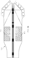
Figure 1 illustrates a plan view of one end of a composite lay-up for a stringer in accordance with a first embodiment; -
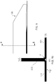
Figure 2 illustrates a side view of the lay-up ofFigure 1 ; -
Figure 3 illustrates a plan view of the lay-up ofFigure 1 having a cover ply; -
Figure 4 illustrates a projection of the lay-up and cover ply ofFigure 3 ; -
Figure 5 illustrates a close up of the stringer termination ofFigure 4 ; -
Figure 6 illustrates the cured, completed stringer of the first embodiment; -
Figure 7 illustrates detail A ofFigure 6 ; -
Figure 8 illustrates a close up of the stack taper ofFigure 7 ; -
Figure 9 illustrates a side view of the stringer ofFigure 6 ; -
Figure 10 illustrates the section view on B-B ofFigure 9 ; -
Figure 11 illustrates an end view of the stringer ofFigure 6 ; -
Figure 12 illustrates a projection of the stringer ofFigure 6 ; -
Figure 13 illustrates a plan view of the stringer ofFigure 6 showing rib feet locations; -
Figure 14 illustrates a schematic view of the ply lay-up to form the stringer of the first embodiment; -
Figure 15 illustrates a schematic view of the cured lay-up ofFigure 14 ; -
Figure 16 illustrates a plan view of a stringer in accordance with a second embodiment; -
Figure 17 illustrates a projection of the stringer ofFigure 16 ; -
Figure 18 illustrates a projection from beneath of the stringer ofFigure 16 ; -
Figure 19 illustrates a schematic view of the ply lay-up to form the stringer of the second embodiment; -
Figure 20 illustrates a schematic view of the cured lay-up ofFigure 18 ; -
Figure 21 illustrates a projection of a stringer in accordance with a third embodiment; -
Figures 22 to 24 illustrate cut away views of the stringer ofFigure 21 installed on a panel and having a pad covering the stringer foot; and -
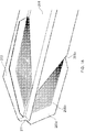
Figure 25 illustrates a schematic view of the stringer ofFigure 21 installed on a panel and having an alternative pad covering the stringer foot, and showing the direction of load transfer from the stringer to the panel. - A first embodiment of a stringer in accordance with the present invention will now be described. As shown in
Figure 1 , thestringer 100 includes aflange 101 having a width W and anupstanding web 102 having a height H. Note that only one end of the stringer is shown inFigure 1 . Thestringer 100 has atermination 103 at one end. Inboard of the termination, thestringer 100 has substantially constant section (not shown inFigure 1 ). Adjacent to thetermination 103, theflange 101 has a region of increased width W' so as to form astringer foot 104. Thestringer 100 is formed from a pair of back-to-back L-shaped stacks of composite laminate plies 105. - The
plies 105 are arranged such that thelowermost ply 105a is the largest ply and theuppermost ply 105b is the smallest ply. The plies are cut such that thelowermost ply 105a terminates at thestringer termination 103, and theuppermost ply 105b terminates a significant distance inboard of thetermination 103. The remainingplies 105 intermediate theplies termination 103. - As can be seen from
Figure 1 the taper of decreasing ply stack thickness in theflange 101 is in both the longitudinal direction X and the transverse direction Y. As can be seen fromFigure 2 , the taper of reducing stack thickness in theflange 101 is also in the vertical direction Z. Furthermore, as can be seen fromFigures 1 and 2 , the taper of reducing stack thickness in theweb 102 is in the transverse direction Y. Near thetermination 103, the width W of theflange 101 also tapers, as does the height H of the upstanding web. Thetaper 106 in the width W of theflange 101 is set at approximately 45° to the longitudinal direction X. A second tapered region set at around 5° to the longitudinal direction X helps to blend between thetaper 106 and the constant width section W' of thestringer foot 104. Thetaper 107 in the height H of theweb 102 is set at approximately 30° to the horizontal. The stack ofplies 105 is cut such that only thelowermost ply 105a remains at thetermination 103. - The exposed edges of the cut plies 105 in the tapers of reducing stack thickness in the
flange 101 andweb 102 can be susceptible to delamination. This can be overcome by providing acover ply 105c over theuppermost ply 105b. Thecover ply 105c is dimensioned so as to be at least as large as thelowermost ply 105a such that thecover ply 105c covers all of theother plies 105. As shown inFigure 3 , thecover ply 105c further includesedge portions 108 which extend beyond thelowermost ply 105a. Theseedge portions 108 may be used to fasten thestringer 100 to a panel. It is to be noted that any such fasteners are non-structural and are provided only to prevent peeling of thecover ply 105c from the panel. Fastener holes 109 in theedge portions 108 are shown inFigure 6 . - The
cover ply 105c when applied over the stack of un-cured plies forms a gap at the termination due to the taper of reducing stack thickness in theother plies 105. Thisgap 109 is best seen in the close up view ofFigure 5 . When the lay-up of plies has been completed, curing thestringer 100 causes thecover ply 105c to conform to the taper of reducing stack thickness of theother plies 105 below. -
Figure 6 shows the completed stringer, after cure, where the cover ply 105c forms a continuous outer surface; Detail A ofFigure 6 is shown inFigure 7 ; and a close up of the tapering stack of plies in theweb 102 is shown inFigure 8 . FromFigure 8 it can be seen that theplies 105 are each parallel in the longitudinal direction X and by successively terminating the plies the thickness of the stack in the transverse direction Y reduces to form the taper. Thecover ply 105c is, in fact, formed of twoplies 105c. These cover plies 105c are not parallel to the longitudinal direction X in the taper, but instead conform to the angle of the taper. Thesmall voids 110 between the edges of the cover plies 105c and the remainingplies 105 are filled with resin. -
Figure 9 shows a side view of thestringer 100 andFigure 10 shows the section view on B-B. FromFigure 10 , the pair of back-to-back L-shaped stacks ofcomposite plies 105 in the region of constant cross section on thestringer foot 104 can be seen. Each ply 105 is continuous such that the thickness of theweb portion 102 is double the thickness of theflange portion 101. Due to the minimum radius r dictated by the laminate plies 105, a cleft may be formed between the back-to-back L-shaped stacks. This cleft may be filled with anon-structural filler 111 such that thelower surface 112 of thestringer 100 is substantially planar such that thestringer 100 may be securely bonded to a panel. - An end view of the
stringer 100 is shown inFigure 11 and a projection view of the completedstringer 100 is shown inFigure 12 . Thestringer 100 is intended to be fixed to a cover, or skin, of an aircraft wing. Aircraft wings typically include ribs having cut-outs through which the stringers pass. The ribs are typically connected to the wing cover, or skin, and to the stringers by rib feet.Figure 13 showslocations 113 at which rib feet may be connected to thestringer 100. -
Figure 14 shows a schematic of the lay up of the plies. The plies between thelowermost ply 105a and theuppermost ply 105b form a stepped configuration in the taper of reducing ply stack thickness. The cover plies 105c extend beyond thelowermost ply 105a. The stack of plies is cured in an autoclave whereby applied heat and pressure P cause the cover plies 105c to conform to the taper geometry of theother plies 105.Figure 15 shows the cured plies upon removal from the autoclave. - In the first embodiment described above, the
stringer 100 has a stack of plies having a taper of reducing stack thickness in various directions. A common feature of each of the tapers is that the internal plies are terminated consecutively towards the stringer termination to form the taper of reducing stack thickness. The exposed edges of the upper plies may be covered by the optional cover plies 105c in the completedstringer 100. - In a second embodiment, the
stringer 200 has a similar overall geometry to that of thestringer 100. The primary difference between thestringer 200 of the second embodiment and thestringer 100 of the first embodiment is that in thestringer 200 the internal plies are terminated such that the edges of the plies are not exposed, even when the optional cover ply or plies are not used. Thestringer 200 includes aflange 201, aweb 202, atermination 203, astringer foot 204, ataper 206 of reducing flange width towards thetermination 203, a taper of reducingweb height 207 towards thetermination 203, and a non-structuraltapered noodle 211. The outer geometry of thestringer 200 is similar to that of thestringer 100, with the exception that theweb 202 has constant width up to thetermination 203. This is achieved, despite a taper of reducing stack thickness in the longitudinal direction X of theweb 202, by the taperednoodle 211. - The
flange 201 and theweb 202 are formed by joining two back-to-back L-shaped stacks of laminated composite structural plies, in a similar manner to the construction of thestringer 100. - The key difference between the
stringer 100 and thestringer 200 is best described with reference toFigures 18 to 20 . For thestringer 200, the ply lay up is the reverse of that of thestringer 100. As can be seen inFigure 18 , theplies 205 are laid up such that thesmallest ply 205a is laid first and thelargest ply 205b is laid last. Optional cover plies 205c may subsequently be laid over theply 205b. With reference toFigure 19 , thefirst ply 205a is laid up first. Theuppermost ply 205b (or coverply 205c) is laid last so as to form an overhang. The plies of thestringer 200 may be of the same material as those of thestringer 100. Once the stack ofplies 205 has been assembled it is cured in an autoclave, or the like.Figure 20 shows a schematic partial section view of theplies 205 after cure. Theuppermost ply 205b forms a generally smooth transition over the taper of reducing stack thickness towards thetermination 203, as do the optional cover plies 205c. The internal plies naturally deform and their edges tend towards the normal to the inner mould line (the surface upon which the ply stack is laid). - In the schematic shown in
Figure 20 , theflange 201 includes anextended portion 213 beyond the extent of theweb 202. This may be optionally provided for thestringer 200 where there is a risk of delamination of theflange 201 from the panel to which it is to be connected. Theextended region 213 provides an increased bonding surface and may further be secured to the panel by a fastener, generally indicated byline 214. -
Figures 21 to 24 illustrate a third embodiment of astringer 300. Thestringer 300 includes a stack of plies 305 arranged in a similar manner to those of thestringer 100. That is to say, thelowermost ply 305a is the largest ply and theuppermost ply 305b is the smallest ply. Thestringer foot 304 has a free-form construction of substantially continuous curved edges, in contrast with the angular cut edges of theplies 105 of thestringer 100. The shape of thestringer foot 304 has been optimised for load transfer into a panel to which thestringer 300 is to be attached. However, the curved edges of the plies 305 are more difficult to cut than the straight edges of theplies stringers - To improve bonding of the
stringer foot 304 to a panel 350 apad 370 is laid over thestringer foot 304. Thepad 370 effectively acts as a region of increased panel thickness for thepanel 350. Thepad 370 has a generally semi-circular or D-shaped construction of substantially uniform thickness. The pad may be made of unidirectional or woven fibre composite material. Thepad 370 may be pre-assembled and co-cured with thestringer 300 and thepanel 350 to bond thestringer 300, thepad 370 and thepanel 350 together. Theprefabricated pad 370 may be laid over thestringer foot 304 in an automated process utilising a vacuum pad on a robotic arm for positioning thepad 370 with respect to thestringer 300. - In a second example of the third embodiment, the
pad 370 is replaced by apad 380, as shown inFigure 25 . The outline of theabsent pad 370 is generally indicated by (370) inFigure 25 . The shape of thepad 380 of the second example has been optimised to follow the load-line 381 of the load as it is transferred from thestringer 300 to thepanel 350. Thepad 380 is of substantially uniform thickness and has a divergentproximal end 382, a generally parallelsided mid-section 383, and a forkeddistal end 384. The shape of thepad 380 is more difficult to cut than the simple "D-shaped"pad 370, but provides improved load transfer between thestringer 300 and thepanel 350. - Although the invention has been described above with reference to one or more preferred embodiments, it will be appreciated that various changes or modifications may be made without departing from the scope of the invention as defined in the appended claims.
Claims (20)
- A laminated composite stringer (100, 200, 300) having a termination (103, 203, 303) at one end in its longitudinal direction, and including a laminated stack of composite structural plies (105, 205, 305), the ply stack having a taper of reducing stack thickness at the stringer termination (103, 203, 303), characteried in that the taper is provided by consecutively terminating the internal plies in the stack towards the stringer termination (103, 203, 303).
- A stringer (100, 200, 300) according to claim 1 having a flange (101, 201, 301), wherein the stack taper is in the flange.
- A stringer (100, 200, 300) according to claim 2, wherein the stack taper in the flange (101, 201, 301) is in the longitudinal and/or transverse direction.
- A stringer (100, 200, 300) according to any preceding claim having an upstanding web (102, 202, 302), wherein the stack taper is in the web.
- A stringer (100, 200, 300) according to claim 4, wherein the web (102, 202, 302) is bifurcated at the termination (103, 203, 303), and wherein a non-structural filler element is disposed in the bifurcated web.
- A stringer (100, 200, 300) according to any preceding claim having a flange (101, 201, 301) and an upstanding web (102, 202, 302) formed by joining a pair of substantially L-shaped stacks of laminated composite structural plies (105, 205, 305) back-to-back.
- A stringer (100, 200, 300) according to claim 4, wherein a non-structural filler element (111) is disposed in a cleft between the L-shaped stacks.
- A stringer (100, 200, 300) according to any preceding claim, having an upstanding web (102, 202, 302), the web having a taper of reducing height at the termination (103, 203, 303).
- A stringer (100, 200, 300) according to any preceding claim having a flange (101, 201, 301), wherein the flange has a taper of reducing width at the termination (103, 203, 303).
- A stringer (100, 200, 300) according to any preceding claim having a flange (101, 201, 301), wherein the width (W) of the flange immediately inboard of the termination (103, 203, 303) is greater than the width of the flange further inboard of the termination (103, 203, 303).
- A composite structure comprising a panel (350) and the stringer (300) of any preceding claim bonded to the panel (350).
- A composite structure according to claim 11, wherein the taper of reducing stack thickness is achieved by terminating plies closest to the panel first.
- A composite structure according to claim 11, wherein the taper of reducing stack thickness is achieved by terminating plies farthest from the panel first.
- An aircraft comprising the composite structure of any of claims 11 to 13.
- A method of manufacturing a laminated composite stringer (100, 200, 300) having a termination (103, 203, 30) at one end in its longitudinal direction, and including a laminated stack of composite structural plies (105, 205, 305), the method comprising:cutting the composite structural plies to a desired termination profile; andstacking the composite structural plies to form the laminated composite stringer, the play stack having a taper of reducing stack thickness at the termination (103, 203, 303), characterised in that the taper is provided by consecutively terminating the internal plies in the stack towards the stringer termination (103, 203, 303).
- A method according to claim 15, wherein the plies are cut by a laser or a water jet.
- A method according to claim 15 or 16, wherein individual plies are cut as they are added to the stack.
- A method according to any of claims 15 to 17, wherein the largest plies of the completed stringer (100, 200, 300) are laid in the stack first.
- A method according to any of claims 15 to 17, wherein the smallest plies of the completed stringer (100, 200, 300) are laid in the stack first.
- A method according to any of claims 15 to 19, further comprising curing the stack of composite structural plies (105, 205, 305).
Applications Claiming Priority (2)
| Application Number | Priority Date | Filing Date | Title |
|---|---|---|---|
| GBGB0912015.5A GB0912015D0 (en) | 2009-07-10 | 2009-07-10 | Stringer |
| PCT/EP2010/059521 WO2011003844A2 (en) | 2009-07-10 | 2010-07-05 | Stringer |
Publications (2)
| Publication Number | Publication Date |
|---|---|
| EP2451703A2 EP2451703A2 (en) | 2012-05-16 |
| EP2451703B1 true EP2451703B1 (en) | 2016-04-27 |
Family
ID=41022469
Family Applications (1)
| Application Number | Title | Priority Date | Filing Date |
|---|---|---|---|
| EP10731504.6A Active EP2451703B1 (en) | 2009-07-10 | 2010-07-05 | Stringer |
Country Status (6)
| Country | Link |
|---|---|
| US (1) | US20120100343A1 (en) |
| EP (1) | EP2451703B1 (en) |
| JP (1) | JP2012532785A (en) |
| CN (1) | CN102470915B (en) |
| GB (1) | GB0912015D0 (en) |
| WO (1) | WO2011003844A2 (en) |
Families Citing this family (52)
| Publication number | Priority date | Publication date | Assignee | Title |
|---|---|---|---|---|
| GB0912015D0 (en) * | 2009-07-10 | 2009-08-19 | Airbus Operations Ltd | Stringer |
| JP5455541B2 (en) * | 2009-10-14 | 2014-03-26 | 三菱重工業株式会社 | Stringer manufacturing method |
| ES2392236B1 (en) * | 2010-01-15 | 2013-10-09 | Airbus Operations, S.L. | AIRCRAFT COMPONENT WITH RIGIDIZED PANELS WITH LARGUERILLOS. |
| US8940213B2 (en) | 2010-06-25 | 2015-01-27 | The Boeing Company | Resin infusion of composite parts using a perforated caul sheet |
| US9682514B2 (en) | 2010-06-25 | 2017-06-20 | The Boeing Company | Method of manufacturing resin infused composite parts using a perforated caul sheet |
| US8636252B2 (en) * | 2010-06-25 | 2014-01-28 | The Boeing Company | Composite structures having integrated stiffeners with smooth runouts and method of making the same |
| US8628717B2 (en) | 2010-06-25 | 2014-01-14 | The Boeing Company | Composite structures having integrated stiffeners and method of making the same |
| ES2393102B1 (en) * | 2010-06-30 | 2013-11-21 | Airbus Operations, S.L. | AIRCRAFT COMPONENT WITH RIGIDIZED PANELS WITH LARGUERILLOS WITH TWO TYPES OF LOCAL STRETCHINGS. |
| ITTO20110421A1 (en) * | 2011-05-12 | 2012-11-13 | Alenia Aeronautica Spa | STRUCTURAL ELEMENT WITH ALA AVENTE BORDO NET, AND ITS MANUFACTURING PROCESS |
| ES2405155B1 (en) * | 2011-10-24 | 2014-09-02 | Airbus Operations S.L. | TERMINATION AREAS OF OPTIMIZED LARGUERILLOS IN AIRCRAFT COMPONENTS |
| US9010688B2 (en) * | 2012-02-07 | 2015-04-21 | The Boeing Company | Structural joint having continuous skin with inside and outside stringers |
| US8974886B2 (en) * | 2012-04-25 | 2015-03-10 | The Boeing Company | Disbond resistant composite stiffener runout |
| GB201209439D0 (en) * | 2012-05-28 | 2012-07-11 | Airbus Operations Ltd | A securing plate and aircraft structure |
| EP2888095B1 (en) * | 2012-08-21 | 2020-09-30 | Saab Ab | A reinforced structure and a method for manufacturing a reinforced structure |
| EP2706008A1 (en) * | 2012-09-07 | 2014-03-12 | Airbus Operations GmbH | Structural component |
| US9272769B2 (en) * | 2012-11-13 | 2016-03-01 | The Boeing Company | Joint for composite wings |
| EP2989003A4 (en) * | 2013-04-25 | 2016-12-07 | Saab Ab | Stiffening element run-out |
| EP2799220B1 (en) | 2013-04-30 | 2020-06-17 | Airbus Operations S.L. | Composite structure for an aircraft and manufacturing method thereof |
| ES2626352T3 (en) | 2013-05-30 | 2017-07-24 | Airbus Operations S.L. | Hybrid tool to cure composite parts |
| US9926067B1 (en) * | 2013-06-10 | 2018-03-27 | The Boeing Company | Stringer flange extending to composite skin edge |
| JP6204093B2 (en) * | 2013-07-12 | 2017-09-27 | 三菱重工業株式会社 | Method for manufacturing reinforcing structure |
| JP6204092B2 (en) * | 2013-07-12 | 2017-09-27 | 三菱重工業株式会社 | Method for manufacturing reinforcing structure |
| US10479475B2 (en) | 2013-08-09 | 2019-11-19 | The Boeing Company | Composite stringer beam joint structure of an aircraft |
| US10029780B2 (en) | 2013-08-09 | 2018-07-24 | The Boeing Company | Stiffened composite panels |
| JP6103239B2 (en) * | 2013-10-31 | 2017-03-29 | 株式会社豊田自動織機 | Reinforced beam material |
| US10086922B2 (en) * | 2013-11-15 | 2018-10-02 | The Boeing Company | Low stress stiffener runout in Pi bonded structure |
| JP6176090B2 (en) * | 2013-12-02 | 2017-08-09 | 株式会社豊田自動織機 | Three-dimensional fiber structure and reinforcement |
| CA2940503A1 (en) | 2014-03-04 | 2015-09-11 | Bombardier Inc. | Method and apparatus for forming a composite laminate stack using a breathable polyethylene vacuum film |
| US10195817B2 (en) * | 2015-01-02 | 2019-02-05 | The Boeing Company | Skin-stringer design for composite wings |
| US9809297B2 (en) | 2015-08-26 | 2017-11-07 | The Boeing Company | Structures containing stiffeners having transition portions |
| US9757906B2 (en) | 2015-08-31 | 2017-09-12 | The Boeing Company | Methods of making composite charges |
| US9808988B2 (en) * | 2015-11-30 | 2017-11-07 | The Boeing Company | Carbon fiber reinforced plastic (CFRP) stringer termination softening with stacked CFRP noodle |
| GB2552216A (en) * | 2016-07-14 | 2018-01-17 | Airbus Operations Ltd | Stiffened aerospace structure and method of manufacture |
| JP6298901B1 (en) * | 2016-07-21 | 2018-03-20 | 株式会社ジャムコ | CFRP member and lattice structure |
| US10207789B2 (en) * | 2016-08-16 | 2019-02-19 | The Boeing Company | Aircraft composite wingbox integration |
| JP6949474B2 (en) * | 2016-11-24 | 2021-10-13 | 三菱重工業株式会社 | Composite material and method of molding composite material |
| JP7090409B2 (en) | 2017-08-30 | 2022-06-24 | 三菱重工業株式会社 | Composite structure |
| JP7019539B2 (en) | 2018-10-04 | 2022-02-15 | 三菱重工業株式会社 | Method of manufacturing a structure using a composite material |
| US11180238B2 (en) * | 2018-11-19 | 2021-11-23 | The Boeing Company | Shear ties for aircraft wing |
| US10919256B2 (en) * | 2019-05-09 | 2021-02-16 | The Boeing Company | Composite structure having a variable gage and methods for forming a composite structure having a variable gage |
| US10913215B2 (en) * | 2019-05-09 | 2021-02-09 | The Boeing Company | Composite structure having a variable gage and methods for forming a composite structure having a variable gage |
| US10919260B2 (en) * | 2019-05-09 | 2021-02-16 | The Boeing Company | Composite structure having a variable gage and methods for forming a composite structure having a variable gage |
| CN113950410B (en) * | 2019-06-13 | 2023-03-31 | 小利兰·斯坦福大学托管委员会 | Composite structure with limited length of tape and methods of making and using same |
| ES2955386T3 (en) * | 2019-09-05 | 2023-11-30 | Airbus Operations Slu | Method of manufacturing a composite material structure using a co-curing process |
| FR3103782B1 (en) * | 2019-12-02 | 2024-03-15 | Latecoere | Aircraft pressurized cabin door with structure formed of beams with scalable section |
| US11718047B2 (en) * | 2019-12-12 | 2023-08-08 | The Boeing Company | Flyaway stringer end caps |
| US11806948B2 (en) * | 2019-12-12 | 2023-11-07 | The Boeing Company | Method of forming flyaway stringer end caps |
| IT202000018136A1 (en) * | 2020-07-27 | 2022-01-27 | Leonardo Spa | PROCEDURE FOR THE MANUFACTURING OF A STRUCTURAL COMPONENT IN COMPOSITE MATERIAL STRENGTHENED WITH AT LEAST ONE BEAM |
| CN112078141B (en) * | 2020-09-21 | 2022-06-10 | 中航复合材料有限责任公司 | Reinforcing rib for composite material wall plate and use method |
| FR3116755A1 (en) * | 2020-11-30 | 2022-06-03 | Airbus Operations (S.A.S.) | Process for manufacturing a stiffened panel comprising reinforcements with beveled ends and stiffened panel obtained from said process |
| US11752707B2 (en) | 2021-05-13 | 2023-09-12 | The Board Of Trustees Of The Leland Stanford Junior University | Octogrid constructions and applications utilizing double-double laminate structures |
| US20250083399A1 (en) * | 2022-01-13 | 2025-03-13 | Invibio Device Component Manufacturing Limited | A compression moulded body |
Citations (1)
| Publication number | Priority date | Publication date | Assignee | Title |
|---|---|---|---|---|
| US4606961A (en) * | 1984-10-09 | 1986-08-19 | The Boeing Company | Discretely stiffened composite panel |
Family Cites Families (20)
| Publication number | Priority date | Publication date | Assignee | Title |
|---|---|---|---|---|
| FR568758A (en) * | 1923-07-17 | 1924-04-01 | Improvements in the construction of aviation wings | |
| US4012549A (en) * | 1974-10-10 | 1977-03-15 | General Dynamics Corporation | High strength composite structure |
| US4331723A (en) * | 1980-11-05 | 1982-05-25 | The Boeing Company | Advanced composite |
| US5451015A (en) * | 1993-05-18 | 1995-09-19 | Bell Helicopter Textron Inc. | Crashworthy composite aircraft structure with integral fuel tank |
| DE19832441C1 (en) * | 1998-07-18 | 2000-01-05 | Daimler Chrysler Aerospace | Stringer-reinforced shell production with double curvature using fibrous composite materials, without risk of warping |
| US7238409B1 (en) * | 2002-05-23 | 2007-07-03 | Rohr, Inc. | Structural element with rib-receiving member |
| FR2848492B1 (en) * | 2002-12-13 | 2006-12-29 | Saint Gobain Vetrotex | METHOD AND DEVICE FOR MANUFACTURING A COMPOSITE PLATE |
| FR2866626B1 (en) | 2004-02-20 | 2006-05-19 | Airbus France | OFFSET OF STIFF SLITTED SLOPES AND PANEL PROVIDED WITH SUCH A STOP |
| US7655581B2 (en) * | 2005-11-17 | 2010-02-02 | Albany Engineered Composites, Inc. | Hybrid three-dimensional woven/laminated struts for composite structural applications |
| US7943535B2 (en) * | 2005-11-17 | 2011-05-17 | Albany Engineered Composites, Inc. | Hybrid three-dimensional woven/laminated struts for composite structural applications |
| BRPI0520816B1 (en) * | 2005-12-30 | 2016-12-13 | Airbus Operations Sl | “process for manufacturing panels for aeronautical structures with u-shaped stiffening members and i-shaped stiffening members between their webs” |
| EP1840775A1 (en) * | 2006-03-31 | 2007-10-03 | Airbus Espana, S.L. | Computer-aided method of obtaining a ply model of composite component |
| US8920698B2 (en) * | 2006-08-17 | 2014-12-30 | Airbus Operations Gmbh | Production method for a workpiece composed of a fibre-composite material |
| WO2008090911A1 (en) * | 2007-01-26 | 2008-07-31 | Toray Industries, Inc. | Preform for molding fiber-reinforced resin beam, process for producing the same, apparatus for producing the same, and process for producing fiber-reinforced resin beam |
| JP4908266B2 (en) * | 2007-03-05 | 2012-04-04 | 株式会社ジャムコ | Method for continuously forming composite material having stepwise cross-sectional thickness |
| GB0708333D0 (en) | 2007-04-30 | 2007-06-06 | Airbus Uk Ltd | Composite structure |
| ES2343824B1 (en) * | 2007-12-21 | 2011-07-18 | Airbus España S.L. | PART OF COMPOSITE MATERIAL WITH ZONES OF DIFFERENT THICKNESS. |
| US7985111B2 (en) * | 2008-04-22 | 2011-07-26 | Gianfranco Gasparro | Sport boards with carbon fiber stringers |
| US8074694B2 (en) * | 2009-05-28 | 2011-12-13 | The Boeing Company | Stringer transition method |
| GB0912015D0 (en) * | 2009-07-10 | 2009-08-19 | Airbus Operations Ltd | Stringer |
-
2009
- 2009-07-10 GB GBGB0912015.5A patent/GB0912015D0/en not_active Ceased
-
2010
- 2010-07-05 EP EP10731504.6A patent/EP2451703B1/en active Active
- 2010-07-05 JP JP2012518931A patent/JP2012532785A/en active Pending
- 2010-07-05 US US13/380,285 patent/US20120100343A1/en not_active Abandoned
- 2010-07-05 CN CN201080030987.1A patent/CN102470915B/en not_active Expired - Fee Related
- 2010-07-05 WO PCT/EP2010/059521 patent/WO2011003844A2/en not_active Ceased
Patent Citations (1)
| Publication number | Priority date | Publication date | Assignee | Title |
|---|---|---|---|---|
| US4606961A (en) * | 1984-10-09 | 1986-08-19 | The Boeing Company | Discretely stiffened composite panel |
Non-Patent Citations (1)
| Title |
|---|
| ENZO COSENTINO ET AL: "Nonlinear Analytical Approach for Preliminary Sizing of Discrete Composite Stringer Terminations", AIAA JOURNAL, vol. 47, no. 3, 1 March 2009 (2009-03-01), pages 606 - 617, XP055167945, ISSN: 0001-1452, DOI: 10.2514/1.37745 * |
Also Published As
| Publication number | Publication date |
|---|---|
| JP2012532785A (en) | 2012-12-20 |
| EP2451703A2 (en) | 2012-05-16 |
| WO2011003844A3 (en) | 2011-06-30 |
| CN102470915A (en) | 2012-05-23 |
| US20120100343A1 (en) | 2012-04-26 |
| GB0912015D0 (en) | 2009-08-19 |
| CN102470915B (en) | 2016-03-30 |
| WO2011003844A2 (en) | 2011-01-13 |
Similar Documents
| Publication | Publication Date | Title |
|---|---|---|
| US20120100343A1 (en) | Stringer | |
| EP3138769B1 (en) | Radius filler containing vertical ply stacks and thin plies | |
| EP2552678B1 (en) | Composite stringer and method of manufacturing a composite stringer | |
| CA2768957C (en) | Composite-material structure and aircraft main wing and aircraft fuselage provided with the same | |
| EP2671794B1 (en) | Composite material structure, and aircraft wing and fuselage provided therewith | |
| EP2689918B1 (en) | Laminated composite bending and stiffening members with reinforcement by inter-laminar metal sheets | |
| CN101547786B (en) | Composite structure | |
| US8844872B2 (en) | Composite structure | |
| EP2492087A1 (en) | Composite structure comprising a first section, a second section and a curved corner | |
| EP2621802B1 (en) | Stiffener run-out | |
| CN101674929A (en) | Composite structure and method of transmitting force comprising stringers with pads embedded in recesses of panels | |
| EP2965984A1 (en) | Clip for ribs and stringers in an aircraft structure | |
| US9027881B2 (en) | Composite material structure and aircraft wing provided therewith | |
| EP2965983A1 (en) | Clip for ribs and stringers in an aircraft structure | |
| CA2815966C (en) | Composite material structure, and aircraft wing and fuselage provided therewith | |
| JP6968604B2 (en) | Aircraft compound wing box integration | |
| EP3597525A1 (en) | Curved composite part and manufacturing method thereof | |
| US8708279B2 (en) | Composite structural member with progressive rigidity | |
| US9868508B2 (en) | Rib foot for aircraft wing | |
| US20210403137A1 (en) | Composite laminate for an airframe lifting surface and method for manufacturing thereof | |
| WO2018096933A1 (en) | Composite member and method of forming composite member | |
| EP3805095B1 (en) | Enhanced design for stringer runout terminations on composite panels | |
| US20210122454A1 (en) | Composite laminate for an airframe lifting surface and method for manufacturing thereof |
Legal Events
| Date | Code | Title | Description |
|---|---|---|---|
| PUAI | Public reference made under article 153(3) epc to a published international application that has entered the european phase |
Free format text: ORIGINAL CODE: 0009012 |
|
| 17P | Request for examination filed |
Effective date: 20120110 |
|
| AK | Designated contracting states |
Kind code of ref document: A2 Designated state(s): AL AT BE BG CH CY CZ DE DK EE ES FI FR GB GR HR HU IE IS IT LI LT LU LV MC MK MT NL NO PL PT RO SE SI SK SM TR |
|
| DAX | Request for extension of the european patent (deleted) | ||
| 17Q | First examination report despatched |
Effective date: 20130619 |
|
| REG | Reference to a national code |
Ref country code: DE Ref legal event code: R079 Ref document number: 602010032837 Country of ref document: DE Free format text: PREVIOUS MAIN CLASS: B64C0001060000 Ipc: B29D0099000000 |
|
| GRAP | Despatch of communication of intention to grant a patent |
Free format text: ORIGINAL CODE: EPIDOSNIGR1 |
|
| INTG | Intention to grant announced |
Effective date: 20151106 |
|
| RIC1 | Information provided on ipc code assigned before grant |
Ipc: B29C 70/30 20060101ALI20151023BHEP Ipc: B29D 99/00 20100101AFI20151023BHEP Ipc: B64C 1/06 20060101ALI20151023BHEP |
|
| GRAS | Grant fee paid |
Free format text: ORIGINAL CODE: EPIDOSNIGR3 |
|
| GRAA | (expected) grant |
Free format text: ORIGINAL CODE: 0009210 |
|
| AK | Designated contracting states |
Kind code of ref document: B1 Designated state(s): AL AT BE BG CH CY CZ DE DK EE ES FI FR GB GR HR HU IE IS IT LI LT LU LV MC MK MT NL NO PL PT RO SE SI SK SM TR |
|
| REG | Reference to a national code |
Ref country code: GB Ref legal event code: FG4D |
|
| REG | Reference to a national code |
Ref country code: CH Ref legal event code: EP |
|
| REG | Reference to a national code |
Ref country code: AT Ref legal event code: REF Ref document number: 794253 Country of ref document: AT Kind code of ref document: T Effective date: 20160515 |
|
| REG | Reference to a national code |
Ref country code: IE Ref legal event code: FG4D |
|
| REG | Reference to a national code |
Ref country code: DE Ref legal event code: R096 Ref document number: 602010032837 Country of ref document: DE |
|
| REG | Reference to a national code |
Ref country code: FR Ref legal event code: PLFP Year of fee payment: 7 |
|
| REG | Reference to a national code |
Ref country code: LT Ref legal event code: MG4D |
|
| REG | Reference to a national code |
Ref country code: NL Ref legal event code: MP Effective date: 20160427 |
|
| REG | Reference to a national code |
Ref country code: AT Ref legal event code: MK05 Ref document number: 794253 Country of ref document: AT Kind code of ref document: T Effective date: 20160427 |
|
| PG25 | Lapsed in a contracting state [announced via postgrant information from national office to epo] |
Ref country code: NL Free format text: LAPSE BECAUSE OF FAILURE TO SUBMIT A TRANSLATION OF THE DESCRIPTION OR TO PAY THE FEE WITHIN THE PRESCRIBED TIME-LIMIT Effective date: 20160427 |
|
| PG25 | Lapsed in a contracting state [announced via postgrant information from national office to epo] |
Ref country code: NO Free format text: LAPSE BECAUSE OF FAILURE TO SUBMIT A TRANSLATION OF THE DESCRIPTION OR TO PAY THE FEE WITHIN THE PRESCRIBED TIME-LIMIT Effective date: 20160727 Ref country code: PL Free format text: LAPSE BECAUSE OF FAILURE TO SUBMIT A TRANSLATION OF THE DESCRIPTION OR TO PAY THE FEE WITHIN THE PRESCRIBED TIME-LIMIT Effective date: 20160427 Ref country code: LT Free format text: LAPSE BECAUSE OF FAILURE TO SUBMIT A TRANSLATION OF THE DESCRIPTION OR TO PAY THE FEE WITHIN THE PRESCRIBED TIME-LIMIT Effective date: 20160427 Ref country code: FI Free format text: LAPSE BECAUSE OF FAILURE TO SUBMIT A TRANSLATION OF THE DESCRIPTION OR TO PAY THE FEE WITHIN THE PRESCRIBED TIME-LIMIT Effective date: 20160427 |
|
| PGFP | Annual fee paid to national office [announced via postgrant information from national office to epo] |
Ref country code: DE Payment date: 20160722 Year of fee payment: 7 |
|
| PG25 | Lapsed in a contracting state [announced via postgrant information from national office to epo] |
Ref country code: LV Free format text: LAPSE BECAUSE OF FAILURE TO SUBMIT A TRANSLATION OF THE DESCRIPTION OR TO PAY THE FEE WITHIN THE PRESCRIBED TIME-LIMIT Effective date: 20160427 Ref country code: SE Free format text: LAPSE BECAUSE OF FAILURE TO SUBMIT A TRANSLATION OF THE DESCRIPTION OR TO PAY THE FEE WITHIN THE PRESCRIBED TIME-LIMIT Effective date: 20160427 Ref country code: AT Free format text: LAPSE BECAUSE OF FAILURE TO SUBMIT A TRANSLATION OF THE DESCRIPTION OR TO PAY THE FEE WITHIN THE PRESCRIBED TIME-LIMIT Effective date: 20160427 Ref country code: PT Free format text: LAPSE BECAUSE OF FAILURE TO SUBMIT A TRANSLATION OF THE DESCRIPTION OR TO PAY THE FEE WITHIN THE PRESCRIBED TIME-LIMIT Effective date: 20160829 Ref country code: HR Free format text: LAPSE BECAUSE OF FAILURE TO SUBMIT A TRANSLATION OF THE DESCRIPTION OR TO PAY THE FEE WITHIN THE PRESCRIBED TIME-LIMIT Effective date: 20160427 Ref country code: ES Free format text: LAPSE BECAUSE OF FAILURE TO SUBMIT A TRANSLATION OF THE DESCRIPTION OR TO PAY THE FEE WITHIN THE PRESCRIBED TIME-LIMIT Effective date: 20160427 Ref country code: GR Free format text: LAPSE BECAUSE OF FAILURE TO SUBMIT A TRANSLATION OF THE DESCRIPTION OR TO PAY THE FEE WITHIN THE PRESCRIBED TIME-LIMIT Effective date: 20160728 |
|
| PGFP | Annual fee paid to national office [announced via postgrant information from national office to epo] |
Ref country code: FR Payment date: 20160721 Year of fee payment: 7 |
|
| PG25 | Lapsed in a contracting state [announced via postgrant information from national office to epo] |
Ref country code: BE Free format text: LAPSE BECAUSE OF FAILURE TO SUBMIT A TRANSLATION OF THE DESCRIPTION OR TO PAY THE FEE WITHIN THE PRESCRIBED TIME-LIMIT Effective date: 20160427 Ref country code: IT Free format text: LAPSE BECAUSE OF FAILURE TO SUBMIT A TRANSLATION OF THE DESCRIPTION OR TO PAY THE FEE WITHIN THE PRESCRIBED TIME-LIMIT Effective date: 20160427 |
|
| REG | Reference to a national code |
Ref country code: DE Ref legal event code: R097 Ref document number: 602010032837 Country of ref document: DE |
|
| PG25 | Lapsed in a contracting state [announced via postgrant information from national office to epo] |
Ref country code: RO Free format text: LAPSE BECAUSE OF FAILURE TO SUBMIT A TRANSLATION OF THE DESCRIPTION OR TO PAY THE FEE WITHIN THE PRESCRIBED TIME-LIMIT Effective date: 20160427 Ref country code: EE Free format text: LAPSE BECAUSE OF FAILURE TO SUBMIT A TRANSLATION OF THE DESCRIPTION OR TO PAY THE FEE WITHIN THE PRESCRIBED TIME-LIMIT Effective date: 20160427 Ref country code: SK Free format text: LAPSE BECAUSE OF FAILURE TO SUBMIT A TRANSLATION OF THE DESCRIPTION OR TO PAY THE FEE WITHIN THE PRESCRIBED TIME-LIMIT Effective date: 20160427 Ref country code: DK Free format text: LAPSE BECAUSE OF FAILURE TO SUBMIT A TRANSLATION OF THE DESCRIPTION OR TO PAY THE FEE WITHIN THE PRESCRIBED TIME-LIMIT Effective date: 20160427 Ref country code: CZ Free format text: LAPSE BECAUSE OF FAILURE TO SUBMIT A TRANSLATION OF THE DESCRIPTION OR TO PAY THE FEE WITHIN THE PRESCRIBED TIME-LIMIT Effective date: 20160427 |
|
| PG25 | Lapsed in a contracting state [announced via postgrant information from national office to epo] |
Ref country code: SM Free format text: LAPSE BECAUSE OF FAILURE TO SUBMIT A TRANSLATION OF THE DESCRIPTION OR TO PAY THE FEE WITHIN THE PRESCRIBED TIME-LIMIT Effective date: 20160427 |
|
| REG | Reference to a national code |
Ref country code: CH Ref legal event code: PL |
|
| PLBE | No opposition filed within time limit |
Free format text: ORIGINAL CODE: 0009261 |
|
| STAA | Information on the status of an ep patent application or granted ep patent |
Free format text: STATUS: NO OPPOSITION FILED WITHIN TIME LIMIT |
|
| PG25 | Lapsed in a contracting state [announced via postgrant information from national office to epo] |
Ref country code: MC Free format text: LAPSE BECAUSE OF FAILURE TO SUBMIT A TRANSLATION OF THE DESCRIPTION OR TO PAY THE FEE WITHIN THE PRESCRIBED TIME-LIMIT Effective date: 20160427 |
|
| 26N | No opposition filed |
Effective date: 20170130 |
|
| PG25 | Lapsed in a contracting state [announced via postgrant information from national office to epo] |
Ref country code: CH Free format text: LAPSE BECAUSE OF NON-PAYMENT OF DUE FEES Effective date: 20160731 Ref country code: LI Free format text: LAPSE BECAUSE OF NON-PAYMENT OF DUE FEES Effective date: 20160731 |
|
| REG | Reference to a national code |
Ref country code: IE Ref legal event code: MM4A |
|
| PG25 | Lapsed in a contracting state [announced via postgrant information from national office to epo] |
Ref country code: SI Free format text: LAPSE BECAUSE OF FAILURE TO SUBMIT A TRANSLATION OF THE DESCRIPTION OR TO PAY THE FEE WITHIN THE PRESCRIBED TIME-LIMIT Effective date: 20160427 |
|
| PG25 | Lapsed in a contracting state [announced via postgrant information from national office to epo] |
Ref country code: IE Free format text: LAPSE BECAUSE OF NON-PAYMENT OF DUE FEES Effective date: 20160705 |
|
| PG25 | Lapsed in a contracting state [announced via postgrant information from national office to epo] |
Ref country code: LU Free format text: LAPSE BECAUSE OF NON-PAYMENT OF DUE FEES Effective date: 20160705 |
|
| REG | Reference to a national code |
Ref country code: DE Ref legal event code: R119 Ref document number: 602010032837 Country of ref document: DE |
|
| REG | Reference to a national code |
Ref country code: FR Ref legal event code: ST Effective date: 20180330 |
|
| PG25 | Lapsed in a contracting state [announced via postgrant information from national office to epo] |
Ref country code: DE Free format text: LAPSE BECAUSE OF NON-PAYMENT OF DUE FEES Effective date: 20180201 |
|
| PG25 | Lapsed in a contracting state [announced via postgrant information from national office to epo] |
Ref country code: FR Free format text: LAPSE BECAUSE OF NON-PAYMENT OF DUE FEES Effective date: 20170731 Ref country code: HU Free format text: LAPSE BECAUSE OF FAILURE TO SUBMIT A TRANSLATION OF THE DESCRIPTION OR TO PAY THE FEE WITHIN THE PRESCRIBED TIME-LIMIT; INVALID AB INITIO Effective date: 20100705 Ref country code: CY Free format text: LAPSE BECAUSE OF FAILURE TO SUBMIT A TRANSLATION OF THE DESCRIPTION OR TO PAY THE FEE WITHIN THE PRESCRIBED TIME-LIMIT Effective date: 20160427 |
|
| PG25 | Lapsed in a contracting state [announced via postgrant information from national office to epo] |
Ref country code: TR Free format text: LAPSE BECAUSE OF FAILURE TO SUBMIT A TRANSLATION OF THE DESCRIPTION OR TO PAY THE FEE WITHIN THE PRESCRIBED TIME-LIMIT Effective date: 20160427 Ref country code: MK Free format text: LAPSE BECAUSE OF FAILURE TO SUBMIT A TRANSLATION OF THE DESCRIPTION OR TO PAY THE FEE WITHIN THE PRESCRIBED TIME-LIMIT Effective date: 20160427 Ref country code: IS Free format text: LAPSE BECAUSE OF FAILURE TO SUBMIT A TRANSLATION OF THE DESCRIPTION OR TO PAY THE FEE WITHIN THE PRESCRIBED TIME-LIMIT Effective date: 20160427 Ref country code: MT Free format text: LAPSE BECAUSE OF NON-PAYMENT OF DUE FEES Effective date: 20160731 |
|
| PG25 | Lapsed in a contracting state [announced via postgrant information from national office to epo] |
Ref country code: BG Free format text: LAPSE BECAUSE OF FAILURE TO SUBMIT A TRANSLATION OF THE DESCRIPTION OR TO PAY THE FEE WITHIN THE PRESCRIBED TIME-LIMIT Effective date: 20160427 |
|
| PG25 | Lapsed in a contracting state [announced via postgrant information from national office to epo] |
Ref country code: AL Free format text: LAPSE BECAUSE OF FAILURE TO SUBMIT A TRANSLATION OF THE DESCRIPTION OR TO PAY THE FEE WITHIN THE PRESCRIBED TIME-LIMIT Effective date: 20160427 |
|
| PGFP | Annual fee paid to national office [announced via postgrant information from national office to epo] |
Ref country code: GB Payment date: 20250722 Year of fee payment: 16 |