EP2451223B1 - Generation of HARQ-ACK information and power control of HARQ-ACK signals in TDD systems with downlink of carrier aggregation - Google Patents
Generation of HARQ-ACK information and power control of HARQ-ACK signals in TDD systems with downlink of carrier aggregation Download PDFInfo
- Publication number
- EP2451223B1 EP2451223B1 EP11187651.2A EP11187651A EP2451223B1 EP 2451223 B1 EP2451223 B1 EP 2451223B1 EP 11187651 A EP11187651 A EP 11187651A EP 2451223 B1 EP2451223 B1 EP 2451223B1
- Authority
- EP
- European Patent Office
- Prior art keywords
- dai
- harq
- ack
- missed
- cell
- Prior art date
- Legal status (The legal status is an assumption and is not a legal conclusion. Google has not performed a legal analysis and makes no representation as to the accuracy of the status listed.)
- Active
Links
- 230000002776 aggregation Effects 0.000 title description 4
- 238000004220 aggregation Methods 0.000 title description 4
- 230000005540 biological transmission Effects 0.000 claims description 121
- LJLYTUYNVSHXQB-SOONXTGKSA-N [(2R,3S,4R,5R)-5-(6-aminopurin-9-yl)-3,4-dihydroxyoxolan-2-yl]methyl N-[2-(6-hydroxy-1,3-benzothiazol-2-yl)-1,3-thiazole-4-carbonyl]sulfamate Chemical compound Nc1ncnc2n(cnc12)[C@@H]1O[C@H](COS(=O)(=O)NC(=O)c2csc(n2)-c2nc3ccc(O)cc3s2)[C@@H](O)[C@H]1O LJLYTUYNVSHXQB-SOONXTGKSA-N 0.000 claims description 45
- 238000000034 method Methods 0.000 claims description 31
- 230000004044 response Effects 0.000 claims description 11
- 230000010363 phase shift Effects 0.000 claims description 3
- 208000037918 transfusion-transmitted disease Diseases 0.000 claims 7
- 210000004027 cell Anatomy 0.000 description 187
- 238000013461 design Methods 0.000 description 37
- 101000741965 Homo sapiens Inactive tyrosine-protein kinase PRAG1 Proteins 0.000 description 20
- 102100038659 Inactive tyrosine-protein kinase PRAG1 Human genes 0.000 description 20
- 238000010586 diagram Methods 0.000 description 18
- 230000008569 process Effects 0.000 description 11
- 230000008054 signal transmission Effects 0.000 description 11
- 230000011664 signaling Effects 0.000 description 11
- 238000004891 communication Methods 0.000 description 9
- 238000013507 mapping Methods 0.000 description 7
- 238000013459 approach Methods 0.000 description 4
- 230000006870 function Effects 0.000 description 4
- 230000001427 coherent effect Effects 0.000 description 2
- 125000004122 cyclic group Chemical group 0.000 description 2
- 230000009977 dual effect Effects 0.000 description 2
- 238000003780 insertion Methods 0.000 description 2
- 230000037431 insertion Effects 0.000 description 2
- 102100036409 Activated CDC42 kinase 1 Human genes 0.000 description 1
- 210000003771 C cell Anatomy 0.000 description 1
- 101150069124 RAN1 gene Proteins 0.000 description 1
- 101100355633 Salmo salar ran gene Proteins 0.000 description 1
- 230000003213 activating effect Effects 0.000 description 1
- 230000003044 adaptive effect Effects 0.000 description 1
- 239000000969 carrier Substances 0.000 description 1
- 230000001413 cellular effect Effects 0.000 description 1
- 238000010276 construction Methods 0.000 description 1
- 230000003247 decreasing effect Effects 0.000 description 1
- 230000000593 degrading effect Effects 0.000 description 1
- 230000001419 dependent effect Effects 0.000 description 1
- 230000000694 effects Effects 0.000 description 1
- 239000000284 extract Substances 0.000 description 1
- 238000000605 extraction Methods 0.000 description 1
- 230000008571 general function Effects 0.000 description 1
- 238000012986 modification Methods 0.000 description 1
- 230000004048 modification Effects 0.000 description 1
- 238000012545 processing Methods 0.000 description 1
- 230000009467 reduction Effects 0.000 description 1
- 230000001052 transient effect Effects 0.000 description 1
- 230000007704 transition Effects 0.000 description 1
Images


Classifications
-
- H—ELECTRICITY
- H04—ELECTRIC COMMUNICATION TECHNIQUE
- H04W—WIRELESS COMMUNICATION NETWORKS
- H04W52/00—Power management, e.g. TPC [Transmission Power Control], power saving or power classes
- H04W52/04—TPC
- H04W52/06—TPC algorithms
- H04W52/14—Separate analysis of uplink or downlink
- H04W52/146—Uplink power control
-
- H—ELECTRICITY
- H04—ELECTRIC COMMUNICATION TECHNIQUE
- H04L—TRANSMISSION OF DIGITAL INFORMATION, e.g. TELEGRAPHIC COMMUNICATION
- H04L5/00—Arrangements affording multiple use of the transmission path
- H04L5/0001—Arrangements for dividing the transmission path
- H04L5/0003—Two-dimensional division
- H04L5/0005—Time-frequency
- H04L5/0007—Time-frequency the frequencies being orthogonal, e.g. OFDM(A), DMT
- H04L5/001—Time-frequency the frequencies being orthogonal, e.g. OFDM(A), DMT the frequencies being arranged in component carriers
-
- H—ELECTRICITY
- H04—ELECTRIC COMMUNICATION TECHNIQUE
- H04W—WIRELESS COMMUNICATION NETWORKS
- H04W72/00—Local resource management
- H04W72/20—Control channels or signalling for resource management
- H04W72/21—Control channels or signalling for resource management in the uplink direction of a wireless link, i.e. towards the network
-
- H—ELECTRICITY
- H04—ELECTRIC COMMUNICATION TECHNIQUE
- H04L—TRANSMISSION OF DIGITAL INFORMATION, e.g. TELEGRAPHIC COMMUNICATION
- H04L5/00—Arrangements affording multiple use of the transmission path
- H04L5/003—Arrangements for allocating sub-channels of the transmission path
- H04L5/0053—Allocation of signaling, i.e. of overhead other than pilot signals
- H04L5/0055—Physical resource allocation for ACK/NACK
-
- H—ELECTRICITY
- H04—ELECTRIC COMMUNICATION TECHNIQUE
- H04L—TRANSMISSION OF DIGITAL INFORMATION, e.g. TELEGRAPHIC COMMUNICATION
- H04L5/00—Arrangements affording multiple use of the transmission path
- H04L5/0091—Signaling for the administration of the divided path
-
- H—ELECTRICITY
- H04—ELECTRIC COMMUNICATION TECHNIQUE
- H04L—TRANSMISSION OF DIGITAL INFORMATION, e.g. TELEGRAPHIC COMMUNICATION
- H04L5/00—Arrangements affording multiple use of the transmission path
- H04L5/14—Two-way operation using the same type of signal, i.e. duplex
-
- H—ELECTRICITY
- H04—ELECTRIC COMMUNICATION TECHNIQUE
- H04L—TRANSMISSION OF DIGITAL INFORMATION, e.g. TELEGRAPHIC COMMUNICATION
- H04L5/00—Arrangements affording multiple use of the transmission path
- H04L5/14—Two-way operation using the same type of signal, i.e. duplex
- H04L5/1469—Two-way operation using the same type of signal, i.e. duplex using time-sharing
-
- H—ELECTRICITY
- H04—ELECTRIC COMMUNICATION TECHNIQUE
- H04W—WIRELESS COMMUNICATION NETWORKS
- H04W52/00—Power management, e.g. TPC [Transmission Power Control], power saving or power classes
- H04W52/04—TPC
- H04W52/18—TPC being performed according to specific parameters
-
- H—ELECTRICITY
- H04—ELECTRIC COMMUNICATION TECHNIQUE
- H04W—WIRELESS COMMUNICATION NETWORKS
- H04W52/00—Power management, e.g. TPC [Transmission Power Control], power saving or power classes
- H04W52/04—TPC
- H04W52/18—TPC being performed according to specific parameters
- H04W52/20—TPC being performed according to specific parameters using error rate
-
- H—ELECTRICITY
- H04—ELECTRIC COMMUNICATION TECHNIQUE
- H04W—WIRELESS COMMUNICATION NETWORKS
- H04W52/00—Power management, e.g. TPC [Transmission Power Control], power saving or power classes
- H04W52/04—TPC
- H04W52/30—TPC using constraints in the total amount of available transmission power
- H04W52/32—TPC of broadcast or control channels
- H04W52/325—Power control of control or pilot channels
-
- H—ELECTRICITY
- H04—ELECTRIC COMMUNICATION TECHNIQUE
- H04W—WIRELESS COMMUNICATION NETWORKS
- H04W52/00—Power management, e.g. TPC [Transmission Power Control], power saving or power classes
- H04W52/04—TPC
- H04W52/38—TPC being performed in particular situations
- H04W52/40—TPC being performed in particular situations during macro-diversity or soft handoff
-
- H—ELECTRICITY
- H04—ELECTRIC COMMUNICATION TECHNIQUE
- H04W—WIRELESS COMMUNICATION NETWORKS
- H04W72/00—Local resource management
- H04W72/04—Wireless resource allocation
-
- H—ELECTRICITY
- H04—ELECTRIC COMMUNICATION TECHNIQUE
- H04W—WIRELESS COMMUNICATION NETWORKS
- H04W72/00—Local resource management
- H04W72/20—Control channels or signalling for resource management
- H04W72/23—Control channels or signalling for resource management in the downlink direction of a wireless link, i.e. towards a terminal
Definitions
- the present invention is generally directed to a wireless communication systems and, more specifically, to the transmission of acknowledgement information in an uplink of a communication system.
- a communication system includes a DownLink (DL) that conveys transmission signals from a Base Station (BS), or NodeB, to User Equipment (UE) and an UpLink (UL) that transmits signals from UEs to the NodeB.
- DL DownLink
- UE User Equipment
- UL UpLink
- a UE also commonly referred to as a terminal or a mobile station, may be fixed or mobile and may be a wireless device, a cellular phone, a personal computer device, a mobile electronic device, or any other similar fixed or mobile electronic device.
- a NodeB is generally a fixed station and may also be referred to as an access point or some other equivalent terminology.
- the UL transmits data signals carrying information content, of control signals providing control information associated with the transmission of data signals in the DL, and of Reference Signals (RSs), which are commonly referred to as pilot signals.
- the DL also conveys transmissions of data signals, control signals, and RSs.
- UL data signals are transmitted through a Physical Uplink Shared CHannel (PUSCH) and DL data signals are conveyed through a Physical Downlink Shared CHannel (PDSCH).
- PUSCH Physical Uplink Shared CHannel
- PDSCH Physical Downlink Shared CHannel
- UCI UL Control Information
- PUCCH Physical Uplink Control CHannel
- a UE may convey UCI together with data through the PUSCH.
- DL control signals may be broadcast or sent in a manner that is UE-specific. Accordingly, UE-specific control channels can be used, among other purposes, to provide UEs with Scheduling Assignments (SAs) for PDSCH reception, or in other words, a DL SA, or a PUSCH transmission, or in other words, a UL SA.
- SAs Scheduling Assignments
- the SAs are transmitted from the NodeB to respective UEs using DL Control Information (DCI) formats through respective Physical DL Control CHannels (PDCCHs).
- DCI DL Control Information
- the NodeB may configure a UE through higher layer signaling, such as Radio Resource Control (RRC) signaling, a PDSCH and a PUSCH Transmission Mode (TM).
- RRC Radio Resource Control
- TM PUSCH Transmission Mode
- the PDSCH TM or PUSCH TM is respectively associated with a DL SA or a UL SA and defines whether the respective PDSCH or PUSCH conveys one data Transport Block (TB) or two data TBs.
- RRC Radio Resource Control
- TM PUSCH Transmission Mode
- PDSCH or PUSCH transmissions are either scheduled to be assigned to a UE by the NodeB through higher layer signaling or through physical layer signaling, such as PDCCH signaling, using a respective DL SA or UL SA, or correspond to non-adaptive retransmissions for a given Hybrid Automatic Repeat reQuest (HARQ) process.
- Scheduling by higher layer signaling is referred to as Semi-Persistent Scheduling (SPS), and scheduling by PDCCH is referred to as dynamic scheduling.
- SPS Semi-Persistent Scheduling
- a PDCCH may also be used to release a SPS PDSCH or a SPS PDSCH. If a UE misses a PDCCH, or in other words, fails to detect a PDCCH, it also misses the associated PDSCH or PUSCH. This event will be referred to as a Discontinuous Transmission (DTX).
- DTX Discontinuous Transmission
- the UCI includes ACKnowledgment (ACK) information associated with a HARQ process, i.e., a HARQ-ACK.
- ACK ACKnowledgment
- the HARQ-ACK information may consist of multiple bits corresponding to positive ACKs for TBs the UE correctly received or negative acknowledgements (NACKs) for TBs the UE incorrectly received.
- NACK negative acknowledgements
- a UE may transmit a DTX, which includes tri-state HARQ-ACK information, or both the absence and the incorrect reception of a TB can be represented by a NACK (in a combined NACK/DTX state).
- TTIs Transmission Time Intervals
- subframes For example, in a frame comprising of 10 subframes, some subframes may be used for DL transmissions and some may be used for UL transmissions.
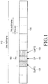
- FIG. 1 illustrates a frame structure for a TDD system according to the related art.
- a 10 millisecond (ms) frame consists of two identical 5 ms half-frames. Each 5 ms half-frame 110 is divided into 8 slots 120 and 3 special fields: a DL Pilot Time Slot (DwPTS) 130, a Guard Period (GP) 140, and an UL Pilot Time Slot (UpPTS) 150.
- the length of DwPTS+GP+UpPTS is one subframe 160 and is 1 ms long.
- the DwPTS may be used for the transmission of synchronization signals from the NodeB while the UpPTS may be used for the transmission of random access signals from UEs.
- the GP facilitates the transition between DL and UL transmissions by absorbing transient interference.
- the number of DL subframes and the number of UL subframes per frame can be different from each other and multiple DL subframes may be associated with a single UL subframe.
- the association between the multiple DL subframes and the single UL subframe is in the sense that HARQ-ACK information of bits generated in response to PDSCH receptions (which are data TBs) in the multiple DL subframes needs to be transmitted in the single UL subframe.
- This number of DL subframes is referred to as the bundling window and, in the example of FIG. 1 , it is usually smaller than or equal to 4 subframes and it is always smaller than or equal to 9 subframes.
- HARQ-ACK bundling One method for a UE to convey HARQ-ACK information in a single UL subframe, in response to receiving PDSCHs in multiple DL subframes, is HARQ-ACK bundling where the UE transmits an ACK only if it correctly receives all data TBs, otherwise, the UE transmits a NACK. Therefore, HARQ-ACK bundling results in unnecessary retransmissions and reduced DL throughput as a NACK is transmitted even when a UE incorrectly receives only one data TB and correctly receives all other data TBs.
- HARQ-ACK multiplexing Another method for a UE to convey HARQ-ACK information in a single UL subframe, in response to receiving data TBs in multiple DL subframes, is HARQ-ACK multiplexing, which is based on PUCCH resource selection.
- Yet another method for a UE to convey HARQ-ACK information in a single UL subframe, in response receiving data TBs in multiple DL subframes, is joint coding of the HARQ-ACK bits using, for example, a block code such as the Reed-Mueller (RM) code, which will be described below.
- RM Reed-Mueller
- the respective HARQ-ACK information consists of one bit which is encoded as a binary '1' if the TB is correctly received, such that the binary '1' indicates an ACK, and is encoded as a binary '0' if the TB is incorrectly received, such that the binary '0' indicates a NACK.
- the HARQ-ACK information consists of two bits o 0 ACK o 1 ACK with o 0 ACK corresponding to the first TB and o 1 ACK corresponding to the second TB. If a UE applies bundling in the spatial domain, it generates only one HARQ-ACK bit.
- the transmission of one HARQ-ACK bit may use repetition coding and the transmission of two HARQ-ACK bits may use a (3, 2) simplex code.
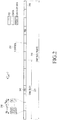
- FIG. 2 illustrates a PUSCH transmission structure according to the related art.
- the subframe 210 includes two slots.
- Each slot 220 includes N symb UL symbols used to transmit data, a HARQ-ACK, or a RS.
- Each symbol 230 includes a Cyclic Prefix (CP) to mitigate interference due to channel propagation effects.
- the PUSCH transmission in one slot may be either at a same BandWidth (BW) or at a different BW than in the other slot.
- Some symbols in each slot are used to transmit RS 240, which enables channel estimation and coherent demodulation of the received data and/or HARQ-ACK information.
- the transmission BW consists of frequency resource units which will be referred to as Physical Resource Blocks (PRBs).
- PRBs Physical Resource Blocks
- M sc PUSCH M PUSCH ⁇ N sc RB REs for the PUSCH transmission BW.
- the last subframe symbol may be used for transmitting a Sounding RS (SRS) 260 from one or more UEs.
- SRS Sounding RS
- the SRS provides the NodeB an estimate of the channel medium the respective UE experiences over the SRS transmission BW.
- the NodeB configures to each UE the SRS transmission parameters through higher layer signaling such as RRC signaling.
- Each RS or SRS is assumed to be constructed using a Constant Amplitude Zero Auto-Correlation (CAZAC) sequence.
- CAZAC Constant Amplitude Zero Auto-Correlation
- Orthogonal multiplexing of CAZAC sequences can be achieved by applying different Cyclic Shifts (CSs) to the same CAZAC sequence.
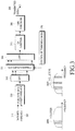
- FIG. 3 illustrates a transmitter for transmitting data and HARQ-ACK in a PUSCH according to the related art.
- encoded HARQ-ACK bits 320 are inserted by puncturing encoded data bits 310 by the data puncturing unit 330.
- a Discrete Fourier Transform (DFT) is then performed by the DFT unit 340.
- the REs for the PUSCH transmission BW are selected by the sub-carrier mapping unit 350 as instructed from a controller 355.
- An Inverse Fast Fourier Transform (IFFT) is performed by an IFFT unit 360, CP insertion is performed by a CP insertion unit 370, and time windowing is performed by a filter 380, thereby generating a transmitted signal 390.
- IFFT Inverse Fast Fourier Transform
- IFFT Inverse Fast Fourier Transform
- CP insertion is performed by a CP insertion unit 370
- time windowing is performed by a filter 380, thereby generating a transmitted signal 390.
- the encoding and modulation processes and additional transmitter circuitry such as a digital-to-analog converter, analog filters, amplifiers,
- the PUSCH transmission is assumed to be over a single cluster 395A or over multiple clusters 395B of contiguous REs in accordance to the DFT Spread Orthogonal Frequency Division Multiple (DFT-S-OFDM) method for signal transmission.
- DFT-S-OFDM DFT Spread Orthogonal Frequency Division Multiple
- FIG. 4 illustrates a receiver for receiving a transmission signal as illustrated in FIG. 3 according to the related art.
- an antenna receives a Radio-Frequency (RF) analog signal and after further processing by units such as filters, amplifiers, and analog-to-digital converters, which are not shown for the purpose of brevity, a received digital signal 410 is filtered by a filter 420 for time windowing and the CP is removed by CP removal unit 430. Subsequently, the receiver unit applies a FFT by an FFT unit 440, selects the REs used by the transmitter by sub-carrier de-mapping by a sub-carrier demapping unit 450 under a control of controller 455. Thereafter, an Inverse DFT (IDFT) unit 460 performs an IDFT, an extraction unit 470 extracts the HARQ-ACK bits and places erasures at the respective REs for the data bits, and finally generates the data bits 480.
- RF Radio-Frequency
- a UE determines the respective number of encoded HARQ-ACK symbols as shown in Equation (1)
- Q ' min ⁇ O HARQ ⁇ ACK ⁇ ⁇ offset HARQ ⁇ ACK Q m ⁇ R ⁇ , 4 ⁇ M sc PUSCH
- O HARQ-ACK is a number of HARQ-ACK information bits, also referred to as a HARQ-ACK payload
- ⁇ offset HARQ ⁇ ACK is a parameter that the NodeB conveys to the UE through higher layer signaling
- R is a data code rate of an initial PUSCH transmission for the same TB
- M sc PUSCH is a PUSCH transmission BW in a current subframe
- ⁇ ⁇ is the ceiling function that rounds a number to a next integer.
- CB is a total number of data code blocks
- K r is a number of bits for a data code block number r
- N symb PUSCH ⁇ initial is a number of subframe symbols for the initial PUSCH transmission of the same TB
- M sc PUSCH ⁇ initial is a number of respective REs for the PUSCH transmission BW.
- the maximum number of encoded HARQ-ACK symbols is limited to the number of REs in 4 DFT-S-OFDM symbols 4 ⁇ M sc PUSCH which may be located in the two subframe symbols adjacent to the RS in each of the two subframe slots, as shown in FIG. 2 .
- the determination of the number of encoded HARQ-ACK symbols in a case where a PUSCH conveys multiple TBs, using for example the SU-MIMO transmission method, is similar to the case where a PUSCH conveys one TB, and thus, a respective description is omitted for brevity.
- FIG. 5 illustrates a PUCCH structure in one subframe slot for the transmission of multiple HARQ-ACK information bits using the DFT-S-OFDM transmission method according to the related art.
- a set of the same HARQ-ACK bits 510 is multiplied by mixer 520 with elements of an Orthogonal Covering Code (OCC) 530 and is subsequently DFT precoded by the precoder unit 540.
- OCC Orthogonal Covering Code
- the OCC has a length of 5 ⁇ OCC(0), OCC(1), OCC(2), OCC(3), OCC(4) ⁇ and can be either of ⁇ 1, 1, 1, 1, 1 ⁇ , or ⁇ 1, exp(j2 ⁇ /5), exp(j4 ⁇ /5), exp(j6 ⁇ /5), exp(j8 ⁇ /5) ⁇ , or ⁇ 1, exp(j4 ⁇ /5), exp(j8 ⁇ /5), exp(j2 ⁇ /5), exp(j6 ⁇ /5) ⁇ , or ⁇ 1, exp(j6 ⁇ /5), exp(j2 ⁇ /5), exp(j8 ⁇ /5), exp(j4 ⁇ /5) ⁇ , or ⁇ 1, exp(j8 ⁇ /5), exp(j6 ⁇ /5), exp(j4 ⁇ /5), exp(j2 ⁇ /5) ⁇ .
- the output of the DFT precoder is passed through an IFFT unit 550 and it is then mapped to a DFT-S-OFDM symbol 560.
- the same or different HARQ-ACK bits may be transmitted in the second subframe slot.
- a RS is also transmitted in each slot to enable coherent demodulation of the HARQ-ACK signals.
- the RS is constructed from a CAZAC sequence 570, having a length of 12, which is passed through an IFFT 580 and mapped to another DFT-S-OFDM symbol 590.
- the PUCCH structure of FIG. 5 can only support limited HARQ-ACK payloads without incurring a large coding rate because it can only support 24 encoded HARQ-ACK bits.
- a single RM code can be used for HARQ-ACK payloads up to 10 bits and a dual RM code can be used for HARQ-ACK payloads between 11 and 20 bits.
- the mapping to successive elements of the DFT can alternate between elements from the output of a first RM code and elements from the output of a second RM code in a sequential manner, which is not shown for brevity.
- convolutional coding can be used for HARQ-ACK payloads of more than 20 bits.
- FIG. 6 illustrates a UE transmitter block diagram for HARQ-ACK signals in a PUCCH according to the related art.
- the HARQ-ACK information bits 605 are encoded and modulated by an encoder and modulator 610 and then multiplied with an element of the OCC 625 for the respective DFT-S-OFDM symbol by a mixer 620.
- the output of the mixer 620 is then precoded by a DFT precoder 630.
- sub-carrier mapping is performed by a sub-carrier mapper 640, under control of controller 650.
- the IFFT is performed by an IFFT unit 660, a CP is added by a CP inserter 670, and the signal is filtered by a filter 680 for time windowing, thereby generating a transmitted signal 690.
- additional transmitter circuitry such as a digital-to-analog converter, analog filters, amplifiers, and transmitter antennas are not illustrated in FIG. 6 .
- FIG. 7 illustrates a NodeB receiver block diagram for HARQ-ACK signals according to the related art.
- the digital received signal 710 is filtered by a filter 720 for time windowing and a CP is removed by a CP remover 730.
- the NodeB receiver applies a FFT by a FFT unit 740, performs sub-carrier demapping by a sub-carrier demapper 750 under the control of a controller 755, and applies an Inverse DFT (IDFT) by an IDFT unit 760.
- the output of the IDFT unit 760 is then multiplied with an OCC element 775 for the respective DFT-S-OFDM symbol by a mixer 770.
- An adder 780 sums the outputs for the DFT-S-OFDM symbols conveying HARQ-ACK signals over each slot, and a demodulator and decoder 790 demodulates and decodes the summed HARQ-ACK signals over both subframe slots in order to obtain the HARQ-ACK information bits 795.
- a DL Assignment Index (DAI) Information Element (IE), or DL DAI IE, V DAI DL , is included in each DL SA in order to assist the UE in determining there is a HARQ-ACK payload it should convey in a PUCCH.
- DAI DL Assignment Index
- V DAI DL is a relative counter which is incremented in each DL SA transmitted to a UE and starts from the beginning after the DL subframe is linked to the UL subframe of the HARQ-ACK signal transmission.
- FIG. 8 illustrates a setting for a DL DAI IE according to the related art.
- a bundling window consists of 4 DL subframes.
- the NodeB does not transmit a DL SA to the UE, and thus, there is no DL DAI IE value.
- a UE does not detect a DL SA transmitted by the NodeB in a subframe other than the last one in a bundling window and detects a DL SA transmitted in a subsequent subframe in the same bundling window, it can infer from the DL DAI IE value of the latter DL SA the number of previous DL SAs it has missed.
- the total number of DL SAs a UE detects in a bundling window is denoted by U DAI . Therefore, a UE can know that it missed V DAI , last DL ⁇ U DAI DL SAs where V DAI , last DL is the DL DAI IE value in the last DL SA that the UE detects in a bundling window.
- the actual number of DL SAs the UE may actually miss can be larger than V DAI , last DL ⁇ U DAI . This happens if the UE misses DL SAs after the last DL SA that it detects.
- a UE may transmit the HARQ-ACK information in the PUSCH.
- a DAI IE is also included in the UL SA so that there is an UL DAI IE to indicate the HARQ-ACK payload. If the PUSCH transmission is not associated with a UL SA, a UE assumes that there is a DL SA in every DL subframe in the bundling window.
- the NodeB can configure a UE with Carrier Aggregation (CA) of multiple cells to provide higher operating BWs.
- CA Carrier Aggregation
- a CA of three cells of 20 MHz each can be used.
- the UE generates separate HARQ-ACK information for the respective TBs it receives in each cell. This is similar to single-cell TDD operations, where the UE generates separate HARQ-ACK information for the respective TBs it receives in each DL subframe for which the HARQ-ACK transmission is in the same UL subframe.
- the NodeB using higher layer signaling, can configure a set of C cells to a UE and activate a subset of A cells ( A ⁇ C ) for PDSCH reception in a subframe, using for example Medium Access Control (MAC) signaling, however a UE may not transmit or receive in inactive cells. If a PDSCH activating or deactivating configured cells is missed, the UE and the NodeB may have a different understanding of the active cells. Moreover, in order to maintain communication, one cell with a DL/UL pair always remains active and is referred to as a Primary cell (Pcell). PUCCH transmissions from a UE are assumed to be only in its Pcell and HARQ-ACK information is conveyed only in a single PUSCH.
- Pcell Primary cell
- FIG. 9 illustrates a parallelization of the DL DAI IE design in FIG. 8 for operation with multiple DL cells according to the related art.
- a NodeB transmits DL SAs to a UE in 3 DL subframes in Cell 0 910 and sets the respective DL DAI IE values according to the number of DL SAs transmitted to the UE only for PDSCH transmissions in Cell 0 910.
- the NodeB transmits DL SAs to the UE in 2 DL subframes in Cell 1 920 and 2 DL subframes in Cell 2 930 and sets the DL DAI IE values according to the number of DL SAs transmitted to the UE only for PDSCH transmissions in Cell 1 920 and Cell 2 930, respectively.
- Alternate designs to the parallelization of the DL DAI design for PDSCH transmission in a single DL cell to multiple DL cells can be based on a joint DL DAI design across DL cells and DL subframes. For each DL subframe in the bundling window, the DL DAI counter operates first in the cell-domain before continuing to the next DL subframe in the bundling window.
- FIG. 10 illustrates an operation of a joint DL DAI design across cells and DL subframes according to the related art.
- DL DAI IE values are shown only for DL subframes and configured DL cells where the NodeB transmits a DL SA to a UE.
- the DL DAI counter starts from DL subframe 0 in Cell 0 1010 and continues in the cell-domain DL subframe 0 for Cell 1 1020 and Cell 2 1030. After all DL SAs across the DL cells in DL subframe 0 are counted, the DL DAI counter continues sequentially for the remaining DL subframes in the bundling window in the same manner as used for the DL subframe 0.
- the fundamental conditions to properly convey HARQ-ACK information to the NodeB remain the same as for single-cell communication.
- the UE and the NodeB should have the same understanding of O HARQ-ACK .
- the PUSCH transmission power is determined by assuming a data transmission and as the transmission powers of HARQ-ACK REs and data REs are the same, the HARQ-ACK reception reliability depends on the number of respective PUSCH REs which scales linearly with O HARQ-ACK as indicated in Equation (1). Therefore, whenever possible, O HARQ-ACK should not be a maximum value in order to avoid unnecessarily consuming PUSCH REs.
- TM PDSCH Transmission Mode
- the UE may transmit a NACK or a DTX (in a case of tri-state HARQ-ACK information) for the TBs it did not receive, however, the NodeB already knows of the DL cells with no DL SA or PDSCH transmission to the UE and can use the knowledge that the UE transmits a NACK for each of those DL cells (a priori information) to improve the HARQ-ACK reception reliability.
- PUCCH transmissions with larger power than necessary increase UE power consumption and create additional interference degrading the reception reliability of signals transmitted by UEs in the same BW in other cells.
- PUCCH transmission power P PUCCH ( i ) in UL subframe i is assumed to be given as shown in equation (3), which is in units of decibels (dBs) per milliwatt (dBm).
- P PUCCH i min P CMAX , c , h n HARQ ⁇ ACK i + F i
- P CMAX,c the maximum allowed UE transmission power in its Pcell
- h ( n HARQ-ACK ( i )) is a monotonically increasing function of the n HARQ-ACK ( i ) HARQ-ACK information bits the UE assumes it is transmitting
- F ( i ) is a general function capturing all other parameters affecting P PUCCH ( i ) in UL subframe i .
- h ( n HARQ-ACK ( i )) ⁇ ⁇ 10log10( n HARQ-ACK ( i )), with ⁇ being a positive number, or h ( n HARQ-ACK ( i )) can be provided by a table indicating the transmission power as function of n HARQ-ACK ( i ). It is noted that the above expression does not account for possible multiplexing with the HARQ-ACK of additional information, such as a Service Request Indicator (SRI) used by a UE to indicate it has data to transmit.
- SRI Service Request Indicator
- n HARQ-ACK The key issue is for a UE to determine the proper n HARQ-ACK value. If n HARQ-ACK is too small the HARQ-ACK reception reliability is degraded. If n HARQ-ACK is too large, interference and UE battery consumption increase unnecessarily.
- n HARQ-ACK ( i ) is an integer of HARQ-ACKs the UE receives in a respective bundling window. This avoids excessive transmission power, but may underestimate the required transmission power as some DL SAs may be missed, thereby decreasing the HARQ-ACK reception reliability.
- a variation of the second possibility is to consider only the number of activated cells A and the configured TM in each such cell.
- n HARQ-ACQ ( i ) N bundle ⁇ ( A + A 2 ) where A 2 is the number of activated cells with a configured TM conveying 2 TBs.
- a 2 is the number of activated cells with a configured TM conveying 2 TBs.
- excessive transmission power is again not avoided as not all active cells may transmit PDSCH to the UE in every DL subframe in the bundling window.
- a 3-bit absolute counter DL DAI is theoretically needed.
- a 2-bit absolute counter DL DAI is sufficient and the interpretation for the number of DL SAs can be mod4 as 2 error cases (4/5 DL SAs interpreted as 0/1 DL SAs) exist only if the UE misses 4 DL SAs and therefore the respective probability is negligible.
- the absolute counter DL DAI informs a UE only the total number P ⁇ C of DL SAs and does not inform the UE which cells transmitted DL SAs. As a result, the UE cannot know which PDSCH is missing and it cannot properly feedback the HARQ-ACK information.
- a discussion is focused on FDD and TDD common features and a study is provided on a key TDD specific feature, i.e. Downlink Assignment Index, DAI, and its impact on UL ACK/NACK transmission in LTE-A TDD.
- an aspect of the present invention is to provide methods and apparatus for a UE operating in a TDD communication system and configured to have multiple DL cells to determine the HARQ-ACK payload for transmission in a PUSCH and the HARQ-ACK signal transmission power for transmission in a PUCCH while considering the presence and design of a DAI IE in DCI formats scheduling PDSCH receptions by the UE and the presence and design of a DAI IE in DCI formats scheduling PUSCH transmissions by the UE.
- a UE determines the transmission power of HARQ-ACK signal transmission in a PUCCH by determining a parameter that is the sum of two components.
- the first component is equal to a number of TBs received through all configured DL cells and through all DL subframes in the bundling window and does not depend on the transmission mode that the UE is configured to have for PUSCH reception in a respective DL cell.
- the second component is equal to a number of TBs that the UE did not receive but which it can identify as missed.
- the UE using the DL DAI IE values in the DL SAs that it detects, can determine a number of PDSCH that the UE missed in each configured DL cell, although the UE may not necessarily determine all PDSCH that it missed. Then, depending on the respective configured PDSCH transmission mode in each configured DL cell, the UE identifies that it missed PDSCH, and thus, the UE computes a number of TBs assuming that each missed PDSCH conveyed a number of TBs determined by the respective configured transmission mode.
- a UE determines the HARQ-ACK payload for multiplexing in a PUSCH depending on whether the PUSCH is scheduled by an UL SA. If the PUSCH is not scheduled by an UL SA, the UE multiplexes the maximum HARQ-ACK payload, which is equal to the sum of the number of configured DL cells and the number of configured DL cells, with a configured PDSCH transmission mode that enables the transmission of 2 TBs multiplied by a size of the bundling window.
- the UE If the PUSCH is scheduled by an UL SA, the UE considers that the UL DAI IE value of the UL SA is applicable over all configured DL cells and indicates the number of PDSCH transmitted to the UE in each of the configured DL cells. Then, for each of the configured DL cells, the HARQ-ACK payload that the UE generates is equal to the number of TBs associated with the respective configured transmission mode for the PDSCH multiplied by the size of the bundling window.
- exemplary embodiments of the present invention will be described below with reference to Discrete Fourier Transform (DFT)-spread Orthogonal Frequency Division Multiplexing (OFDM) transmission, the exemplary embodiments of the present invention are also applicable to all Frequency Division Multiplexing (FDM) transmissions in general and to Single-Carrier Frequency Division Multiple Access (SC-FDMA) and OFDM in particular.
- DFT Discrete Fourier Transform
- OFDM Orthogonal Frequency Division Multiplexing
- SC-FDMA Single-Carrier Frequency Division Multiple Access
- a User Equipment is assumed to generate Hybrid Automatic Repeat reQuest (HARQ)-ACKnowledgement (ACK) information in response to each Transmission Block (TB) associated with a DownLink (DL) Scheduling Assignment (SA).
- HARQ Hybrid Automatic Repeat reQuest
- ACK acknowledgement
- SA DownLink
- a UE may also deterministically generate HARQ-ACK information associated with each Semi-Persistent Scheduling (SPS) TB the NodeB transmits at predetermined DL subframes without transmitting a respective DL SA.
- SPS Semi-Persistent Scheduling
- the UE includes HARQ-ACK information due to SPS, when it exists, with the HARQ-ACK information it generates in response to DL SAs and a placement of the HARQ-ACK information can be, for example, in the beginning of the overall HARQ-ACK payload. Further explicit reference to HARQ-ACK information in response to SPS TBs is omitted for brevity. Moreover, in the case of a DL SA not being associated with a respective PDSCH (and data TBs), but instead being used to serve other purposes, will also not be explicitly considered. However, a UE is assumed to generate a HARQ-ACK information bit corresponding to such DL SA. The descriptions of the exemplary embodiments consider the configured cells but the same arguments directly apply if the activated cells are instead considered.
- An exemplary embodiment of the present invention describes a method for a UE to determine the transmission power of its HARQ-ACK signal in a Physical Uplink Control Channel (PUCCH) for a Time-Division Duplex (TDD) system using DL Carrier Aggregation (CA).
- the UE is to determine the parameter n HARQ-ACK ( i ) used in the Transmit Power Control (TPC) formula in Equation (3) (for simplicity, an UpLink (UL) subframe index i is omitted in the following analysis).
- TPC Transmit Power Control
- the first step for determining n HARQ-ACK is to determine a first component consisting of the number of HARQ-ACK information bits derived from the received TBs in the DL subframe bundling window, n HARQ ⁇ ACK rTBs , without considering the respective configured Physical Downlink Shared CHannel (PDSCH) Transmission Mode (TM). Consequently, even though a UE may be configured to be in a Single User-Multiple Input Multiple Output (SU-MIMO) TM enabling transmission of 2 TBs in a PDSCH from the NodeB to the UE in a cell, the transmission power accounts for 1 HARQ-ACK bit if the PDSCH reception actually conveys only 1 TB.
- SU-MIMO Single User-Multiple Input Multiple Output
- the PUCCH transmission power does not depend on the configured PDSCH TM for each cell but depends on the number of received TBs in that cell.
- N received ( m , c ) is the number of received TBs in configured cell c in DL subframe m of the bundling window
- the second step in determining the value of n HARQ-ACK is to determine, based on the DL DAI IE, a second component consisting of HARQ-ACK bits corresponding to TBs that were not received, but which can be inferred by a UE as being transmitted by the NodeB using the DL DAI IE in order to determine the PDSCH receptions that the UE has missed.
- the respective number of HARQ-ACK bits considers the configured PDSCH TM in the respective cell of the missed DL SA that the UE identified in order to provide a conservative estimate and always ensure that the HARQ-ACK reception reliability is achieved in a case where the configured PDSCH TM enabled transmission of the 2 TBs to the UE.
- V DAI , last DL c is the DL DAI IE value in the last DL SA that the UE successfully receives in cell c
- TB ( m,c ) is the number of TBs that the UE receives in cell c and subframe j in the bundling window.
- TB ( m,c ) is determined by the maximum number of TBs associated with the configured TM in cell c , TB max ( c ).
- TB max ( c ) is determined by the maximum number of TBs associated with the configured TM in cell c .
- U DAI ( c ) is the total number of DL SAs the UE detects in cell c during the bundling window. The UE knows it misses V DAI , last DL c ⁇ U DAI c DL SAs in cell c.
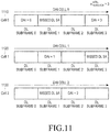
- FIG. 11 illustrates a process for a UE configured with multiple DL cells to determine missed DL SAs assuming the direct parallelization of the DL DAI design in FIG. 9 to multiple DL cells according to an exemplary embodiment of the present invention.
- a UE determines the N DLSA missed missed DL SAs by counting their number based on the DL DAI IE values in the DL SAs it receives.
- the UE assumes that the total number of missed TBs is 3 (2 TBs in Cell 0 and 1 TB in Cell 2).
- n HARQ ⁇ ACK N received + N reset ⁇ N bundle + V DAI , last DL ⁇ U DAI ⁇ T B max
- V DAI,last DL is the last DL DAI IE value for the design in FIG. 10
- FIG. 12 illustrates a process for a UE configured with multiple DL cells to determine missed DL SAs for the DL DAI operation in multiple DL cells as in FIG. 10 according to an exemplary embodiment of the present invention.
- the UE misses the DL SA in DL subframe 1 and it becomes aware of a missed DL SA (although, the UE does not necessarily become aware of the actual missed DL SA) based on the DL DAI IE value in DL subframe 1 1222 of Cell 1 1220.
- the UE misses the DL SA in DL subframe 1 and becomes aware a missed DL SA (again, not necessarily of the actual missed one) based on the DL DAI IE value in DL subframe 2 1232 of Cell 2.
- the UE misses the DL SA in DL subframe 3 but it cannot become aware of this event since it is the last DL SA the NodeB transmits to the UE.
- the UE can identify the missed DL SAs, except for the last one, it may not be able to determine the respective cells. Therefore, the UE may not be able to know the number of TBs it missed and, if spatial bundling is not used, it may not be able to know the respective number of HARQ-ACK bits or the value of n HARQ-ACK .
- the UE cannot know whether the DL SA that was missed in DL subframe 1 of Cell 0 was not transmitted in DL subframe 0 of Cell 1 or Cell 2.
- the UE has configured TMs enabling transmission for a maximum of 2 TBs, 1 TB, and 1 TB, respectively, and the UE needs to assume that it missed the DL SA in Cell 0 in order to avoid underestimating the HARQ-ACK signal transmission power in the PUCCH.
- the remaining TBs i.e., the HARQ-ACK bits used to determine n HARQ-ACK and the HARQ-ACK signal transmission power in the PUCCH are based on the received TBs.
- FIG. 11 and FIG. 12 are only illustrative of two DL DAI designs and are not meant to be exclusive of other designs, but rather the exemplary embodiments are meant to illustrate the use of DL DAI IE in determining the HARQ-ACK payload that the UE assumes when setting the transmission power of the HARQ-ACK signal in the PUCCH.
- the first component may be based on the number of configured or activated cells instead of the number of received TBs.
- the UE may assume that each missed DL SA conveyed 1 TB, in order to avoid HARQ-ACK signal transmission in the PUCCH with larger power than necessary.
- the Q last value may be scaled accordingly. In this manner, the UE does not underestimate the required HARQ-ACK signal transmission power in the PUCCH.
- the number of DL subframes that should be accounted for by Q last may be predetermined or configured for the UE by the NodeB.
- Another exemplary embodiment of the present invention considers the determination of the HARQ-ACK payload in a PUSCH in order for a UE and a NodeB to achieve the same understanding of the transmitted HARQ-ACK information.
- a UE is assumed to generate an ACK or a NACK depending on the reception outcome (correct or incorrect) of each respective TB it receives and to generate a NACK for each TB it identifies as missed.
- a case where no UL SA exists will be discussed below.
- the UE cannot be aware of this event. Therefore, if the HARQ-ACK payload is determined from the number of received TBs, or received DL SAs, this would result in erroneous operation as a UE will not include the respective HARQ-ACK bits in the total HARQ-ACK payload and the NodeB cannot know of the UE missing a DL SA in the last DL subframe.
- a UE may generate a NACK for each TB (or for multiple TBs in a case of spatial bundling) of each DL subframe in which it did not receive a DL SA.
- the trade-off for ensuring proper operation in this manner is the increased HARQ-ACK payload as a NACK is generated for each TB of a DL subframe when the NodeB does not transmit a DL SA to the UE.
- the HARQ-ACK payload in a PUSCH, according to Equation (11), is always the maximum possible value and methods for its possible reduction may be considered.
- the determination of the HARQ-ACK payload is problematic because the DL DAI design in FIG. 10 is across cells where a UE may be configured for TMs enabling reception for different numbers of TBs (1 or 2) and neither the NodeB nor the UE can know which DL SAs were missed. In other words, the UE may have different TMs for different cells, enabling reception for different numbers of TBs in the cells.
- FIG. 13 illustrates an example of a UE configured with multiple DL cells not being able to determine which DL SAs it missed in case of the DL DAI design in FIG. 10 according to an exemplary embodiment of the present invention.
- a UE is configured with a TM enabling the reception of 2 TBs per sub frame in Cell 0 1310 and with a TM enabling the reception of 1 TB per subframe in Cell 1 1320 and Cell 2 1330.
- the UE receives a DL SA in Cell 1, and based on the DAI IE value 1322 it becomes aware of a missed DL SA, which, as shown in FIG. 13 , is missed DL SA 1215.
- the UE cannot know whether the DL SA that it missed was in Cell 0, Cell 1, or Cell 2, there are two possible assumptions the UE can make; either 2 TBs were missed or 1 TB was missed.
- the UE receives a DL SA in Cell 2 and based on the DAI IE value 1332 it becomes aware that it missed another DL SA, which, as shown in FIG. 13 , is missed DL SA 1325.
- the UE cannot know whether the DL SA it missed was in Cell 0, Cell 1, or Cell 2, there are again two possible assumptions the UE can make; either the UE missed 2 TBs or the UE missed 1 TB.
- the latter is the correct assumption while the former is incorrect and will lead to a misunderstanding between the UE and the NodeB of the HARQ-ACK payload.
- the UE generates HARQ-ACK bits according to the configured TM in each cell, it is not possible to achieve the same understanding of the HARQ-ACK payload between the NodeB and the UE when DL SAs are missed.
- the UE should always generate HARQ-ACK bits corresponding to the TM enabling reception for the largest number of TBs regardless of the TM configured in a particular cell.
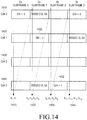
- FIG. 14 illustrates a process for a UE configured with multiple DL cells to determine the HARQ-ACK payload for the DL DAI design in FIG. 10 according to an exemplary embodiment of the present invention.
- a UE is configured to have a TM enabling the reception of 2 TBs per subframe in Cell 0 1410 and a TM enabling the reception of 1 TB per subframe in Cell 1 1420, Cell 2 1430, and Cell 3 1440.
- the UE is configured to have a TM enabling reception of 2 TBs in at least one cell, it generates 2 HARQ-ACK bits for every DL SA it identifies regardless of the TM of the respective cell.
- the UE receives a DL SA for Cell 0 and generates 2 respective HARQ-ACK bits b0, b1 1415.
- the UE receives a DL SA for Cell 1, and based on the respective DL DAI IE value 1422 the UE determines that there was a missed DL SA. Then, the UE generates 4 respective HARQ-ACK bits b2, b3, b4, b5 1425.
- the UE receives a DL SA for Cell 3, and based on the respective DL DAI IE value 1432, the UE determines that there was a missed DL SA. Then, the UE generates 4 respective HARQ-ACK bits b6, b7, b8, b9 1435.
- the UE receives a DL SA for Cell 0 but also generates 2 additional HARQ-ACK bits in case the UE missed a next DL SA at the end of a cell. Therefore, the UE generates 4 respective HARQ-ACK bits b10, b11, b12, b13 1445. This assumes that a probability that the UE misses more than one of the last DL SAs at the end of a cell is negligible. Otherwise, the UE may generate multiple pairs of HARQ-ACK bits corresponding to the multiple possible missed DL SAs after the last missed DL SA that the UE was aware of, as previously discussed above.
- N DAI DL N reset ⁇ N bundel + V DAI , last DL , and by denoting TB max to be the maximum number of TBs for any configured TM in any cell (wherein TB max is 1 or 2, and wherein TB max is always 1 if spatial bundling is applied) and by Q add being the number of additional DL SAs assumed to have been missed by the UE after the last received DL SA (it is noted that Q add may be configured for the UE by the NodeB and appropriately reduced if the UE correctly receives Q add or less of the last DL SAs), then the HARQ-ACK payload is (assuming that DTX is mapped to a NACK) given by Equation (12).
- O HARQ ⁇ ACK N DAI DL + Q add ⁇ T B max
- Equation (12) may be smaller than the one in Equation (11), particularly if spatial domain bundling is applied, Equation (12) may be used to determine the HARQ-ACK payload in a case where the transmission is in the PUSCH.
- Equation (12) The approach used in Equation (12) can also be followed for the DL DAI design in FIG. 9 in order to reduce the HARQ-ACK payload compared to Equation (11), assuming that the probability of the UE missing 2 consecutive DL SAs is negligible.
- Equation (12) the HARQ-ACK payload is given by Equation (13).
- a UE receives an UL SA for a PUSCH transmission in the same UL subframe as the expected HARQ-ACK signal transmission, and the HARQ-ACK information is included in that PUSCH, the related art UL DAI IE cannot be directly re-used as it corresponds only to a single cell and PUSCH transmission may not exist in all cells.
- FIG. 15 illustrates the inability of the related art interpretation of a UL DAI IE in an UL SA to indicate the HARQ-ACK payload a UE should transmit in a respective PUSCH is response to the reception of multiple PDSCH over a bundling window in respective multiple cells for the DL DAI design in FIG. 9 based on the setup of FIG. 11 according to an exemplary embodiment of the present invention.
- the same arguments apply for the DL DAI design in FIG. 10 .
- the UE does not receive a UL SA 1525 and 1535, respectively, the UL DAI IE received in Cell 0 cannot serve the purpose of informing the UE of the number of HARQ-ACK bits it needs to include in the respective PUSCH transmission.
- a UE For the DL DAI design of FIG. 13 , based on the DL DAI IE values in Cell 0, a UE knows that NodeB transmitted 2 DL SAs to the UE. Based on the DL DAI IE values in Cell 1, the UE knows that the NodeB transmitted 1 DL SA, that the UE missed 1 DL SA, and the UE cannot be aware of the missed DL SA in the last DL subframe of the bundling window. Based on the DL DAI IE in Cell 2, the UE knows that the NodeB transmitted 1 DL SA and that the UE missed 1 DL SA. Therefore, the UE can know that the NodeB transmitted 6 DL SAs and that 2 of them were missed by the UE.
- N SA , total DL N DAI DL + V DAI UL ⁇ mod N DAI DL ,4
- the above uncertainty can be resolved by using the UL DAI IE value to indicate a same number of DL SAs transmitted in all cells regardless of the actual number of DL SAs transmitted in each cell.
- the UL DAI IE indicates that there are 3 DL SAs in every cell although the number of actual DL SAs in some cells, such as cell 1, is 2.
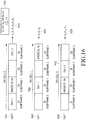
- FIG. 16 illustrates the use of the UL DAI IE in a UL SA for a PUSCH where a UE multiplexes HARQ-ACK information to determine the HARQ-ACK payload and ordering for the DL DAI design in FIG. 9 or in FIG. 10 according to an exemplary embodiment of the present invention.
- a predetermined ordering of cells is assumed, such as one based on the Cell_Index.
- the UE For the DL SAs it receives, the UE generates a HARQ-ACK corresponding to the outcome of the respective reception of TBs, whether the outcome is correct or incorrect.
- the UE can identify that it received 3 DL SAs and, as it is assumed to have been configured with a TM enabling the reception of 2 TBs, the UE generates 6 respective HARQ-ACK bits 1615.
- 3 HARQ-ACK bits are generated.
- the UE can identify that it received 1 DL SA and that the DL SA has a DL DAI IE value 1622 of 1.
- the UE As the UL DAI IE indicates 3 DL SAs 1640, the UE generates 2 additional HARQ-ACK bits placed after the first of the HARQ-ACK bits for a total of 3 HARQ-ACK bits 1625 (the UE is assumed to have been configured with a TM enabling the reception of 1 TB in Cell 1).
- the UE can identify that it received 1 DL SA and that it has a DL DAI IE value 1432 of 2.
- the UE As the UL DAI IE indicates 3 DL SAs 1640, the UE generates 2 additional HARQ-ACK bits with the first one placed before the HARQ-ACK bit corresponding to the TB reception in DL subframe 1 and the other placed after the HARQ-ACK bit corresponding to the TB reception for a total of 3 HARQ-ACK bits 1635. It should be noted that the UE is assumed to have been configured with a TM enabling the reception of 1 TB in Cell 2.
- the UL DAI IE may indicate the total number of DL SAs over all cells. For example, this can be useful if spatial bundling is used since the configured TM in each cell does not affect the respective number of HARQ-ACK bits.
- the mapping of the UL DAI IE value to the total number of DL SAs can be configured for the UE by the NodeB. An example is shown below in Table 1.
- the UL DAI IE may also be extended to include additional bits in a case of DL CA in order to improve the granularity and accuracy of its indications. If a UE does not receive any DL SA, the UL DAI value of "11" is interpreted as 0.
- Table 1 Mapping of UL DAI IE to total DL SAs a UE should assume in the bundling window.
- a UE may not consider the UL DAI IE in any UL SA as valid if it does not have the same value in all UL SAs.
- the UE may either transmit the HARQ-ACK payload determined from the DL DAI IE in a PUSCH or the UE may not transmit any PUSCH as, for proper system operation, this can be considered to represent an error case resulting from either the UE considering as valid an invalid DL SA or by considering as valid an invalid UL SA.
Description
- The present invention is generally directed to a wireless communication systems and, more specifically, to the transmission of acknowledgement information in an uplink of a communication system.
- A communication system includes a DownLink (DL) that conveys transmission signals from a Base Station (BS), or NodeB, to User Equipment (UE) and an UpLink (UL) that transmits signals from UEs to the NodeB. A UE, also commonly referred to as a terminal or a mobile station, may be fixed or mobile and may be a wireless device, a cellular phone, a personal computer device, a mobile electronic device, or any other similar fixed or mobile electronic device. A NodeB is generally a fixed station and may also be referred to as an access point or some other equivalent terminology.
- More specifically, the UL transmits data signals carrying information content, of control signals providing control information associated with the transmission of data signals in the DL, and of Reference Signals (RSs), which are commonly referred to as pilot signals. The DL also conveys transmissions of data signals, control signals, and RSs.
- UL data signals are transmitted through a Physical Uplink Shared CHannel (PUSCH) and DL data signals are conveyed through a Physical Downlink Shared CHannel (PDSCH). In a case where a PUSCH transmission does not occur, a UE conveys UL Control Information (UCI) through a Physical Uplink Control CHannel (PUCCH). However, when a PUSCH transmission occurs, a UE may convey UCI together with data through the PUSCH.
- DL control signals may be broadcast or sent in a manner that is UE-specific. Accordingly, UE-specific control channels can be used, among other purposes, to provide UEs with Scheduling Assignments (SAs) for PDSCH reception, or in other words, a DL SA, or a PUSCH transmission, or in other words, a UL SA. The SAs are transmitted from the NodeB to respective UEs using DL Control Information (DCI) formats through respective Physical DL Control CHannels (PDCCHs).
- The NodeB may configure a UE through higher layer signaling, such as Radio Resource Control (RRC) signaling, a PDSCH and a PUSCH Transmission Mode (TM). The PDSCH TM or PUSCH TM is respectively associated with a DL SA or a UL SA and defines whether the respective PDSCH or PUSCH conveys one data Transport Block (TB) or two data TBs.
- PDSCH or PUSCH transmissions are either scheduled to be assigned to a UE by the NodeB through higher layer signaling or through physical layer signaling, such as PDCCH signaling, using a respective DL SA or UL SA, or correspond to non-adaptive retransmissions for a given Hybrid Automatic Repeat reQuest (HARQ) process. Scheduling by higher layer signaling is referred to as Semi-Persistent Scheduling (SPS), and scheduling by PDCCH is referred to as dynamic scheduling. A PDCCH may also be used to release a SPS PDSCH or a SPS PDSCH. If a UE misses a PDCCH, or in other words, fails to detect a PDCCH, it also misses the associated PDSCH or PUSCH. This event will be referred to as a Discontinuous Transmission (DTX).
- The UCI includes ACKnowledgment (ACK) information associated with a HARQ process, i.e., a HARQ-ACK. The HARQ-ACK information may consist of multiple bits corresponding to positive ACKs for TBs the UE correctly received or negative acknowledgements (NACKs) for TBs the UE incorrectly received. In a case where a UE does not receive a TB, it may transmit a DTX, which includes tri-state HARQ-ACK information, or both the absence and the incorrect reception of a TB can be represented by a NACK (in a combined NACK/DTX state). One consequence of a UE not conveying a DTX to the NodeB is that Incremental Redundancy (IR) cannot be used for its HARQ process. This leads to throughput loss. Another consequence is that PDCCH power control, based on DTX feedback, is not possible.
- In Time Division Duplex (TDD) systems, DL and UL transmissions occur in different Transmission Time Intervals (TTIs) which are referred to as subframes. For example, in a frame comprising of 10 subframes, some subframes may be used for DL transmissions and some may be used for UL transmissions.
-
FIG. 1 illustrates a frame structure for a TDD system according to the related art. - Referring to
FIG. 1 , a 10 millisecond (ms) frame consists of two identical 5 ms half-frames. Each 5 ms half-frame 110 is divided into 8slots subframe 160 and is 1 ms long. The DwPTS may be used for the transmission of synchronization signals from the NodeB while the UpPTS may be used for the transmission of random access signals from UEs. The GP facilitates the transition between DL and UL transmissions by absorbing transient interference. - The number of DL subframes and the number of UL subframes per frame can be different from each other and multiple DL subframes may be associated with a single UL subframe. The association between the multiple DL subframes and the single UL subframe is in the sense that HARQ-ACK information of bits generated in response to PDSCH receptions (which are data TBs) in the multiple DL subframes needs to be transmitted in the single UL subframe. This number of DL subframes is referred to as the bundling window and, in the example of
FIG. 1 , it is usually smaller than or equal to 4 subframes and it is always smaller than or equal to 9 subframes. - One method for a UE to convey HARQ-ACK information in a single UL subframe, in response to receiving PDSCHs in multiple DL subframes, is HARQ-ACK bundling where the UE transmits an ACK only if it correctly receives all data TBs, otherwise, the UE transmits a NACK. Therefore, HARQ-ACK bundling results in unnecessary retransmissions and reduced DL throughput as a NACK is transmitted even when a UE incorrectly receives only one data TB and correctly receives all other data TBs.
- Another method for a UE to convey HARQ-ACK information in a single UL subframe, in response to receiving data TBs in multiple DL subframes, is HARQ-ACK multiplexing, which is based on PUCCH resource selection.
- Yet another method for a UE to convey HARQ-ACK information in a single UL subframe, in response receiving data TBs in multiple DL subframes, is joint coding of the HARQ-ACK bits using, for example, a block code such as the Reed-Mueller (RM) code, which will be described below. The primary focus of the descriptions herein is on joint coding of HARQ-ACK bits. Although the transmission of HARQ-ACK information was described for brevity only for a PUCCH, the coding method is fundamentally the same for transmission in a PUSCH.
- If a PDSCH conveys one TB, the respective HARQ-ACK information consists of one bit which is encoded as a binary '1' if the TB is correctly received, such that the binary '1' indicates an ACK, and is encoded as a binary '0' if the TB is incorrectly received, such that the binary '0' indicates a NACK. If a PDSCH conveys two TBs, in accordance with the Single User-Multiple Input Multiple Output (SU-MIMO) transmission method with a rank higher than one, the HARQ-ACK information consists of two bits


-
FIG. 2 illustrates a PUSCH transmission structure according to the related art. - Referring to
FIG. 2 , thesubframe 210 includes two slots. Eachslot 220 includes
symbol 230 includes a Cyclic Prefix (CP) to mitigate interference due to channel propagation effects. The PUSCH transmission in one slot may be either at a same BandWidth (BW) or at a different BW than in the other slot. Some symbols in each slot are used to transmit RS 240, which enables channel estimation and coherent demodulation of the received data and/or HARQ-ACK information. The transmission BW consists of frequency resource units which will be referred to as Physical Resource Blocks (PRBs). Each PRB includes

- The last subframe symbol may be used for transmitting a Sounding RS (SRS) 260 from one or more UEs. The SRS provides the NodeB an estimate of the channel medium the respective UE experiences over the SRS transmission BW. The NodeB configures to each UE the SRS transmission parameters through higher layer signaling such as RRC signaling. The number of subframe symbols available for data transmission is

- Each RS or SRS is assumed to be constructed using a Constant Amplitude Zero Auto-Correlation (CAZAC) sequence. Orthogonal multiplexing of CAZAC sequences can be achieved by applying different Cyclic Shifts (CSs) to the same CAZAC sequence.
-
FIG. 3 illustrates a transmitter for transmitting data and HARQ-ACK in a PUSCH according to the related art. - Referring to
FIG. 3 , encoded HARQ-ACK bits 320 are inserted by puncturing encodeddata bits 310 by thedata puncturing unit 330. A Discrete Fourier Transform (DFT) is then performed by theDFT unit 340. The REs for the PUSCH transmission BW are selected by thesub-carrier mapping unit 350 as instructed from acontroller 355. An Inverse Fast Fourier Transform (IFFT) is performed by anIFFT unit 360, CP insertion is performed by aCP insertion unit 370, and time windowing is performed by afilter 380, thereby generating a transmittedsignal 390. For brevity, the encoding and modulation processes and additional transmitter circuitry such as a digital-to-analog converter, analog filters, amplifiers, and transmitter antennas are not illustrated. - The PUSCH transmission is assumed to be over a
single cluster 395A or overmultiple clusters 395B of contiguous REs in accordance to the DFT Spread Orthogonal Frequency Division Multiple (DFT-S-OFDM) method for signal transmission. -
FIG. 4 illustrates a receiver for receiving a transmission signal as illustrated inFIG. 3 according to the related art. - Referring to
FIG. 4 , an antenna receives a Radio-Frequency (RF) analog signal and after further processing by units such as filters, amplifiers, and analog-to-digital converters, which are not shown for the purpose of brevity, a receiveddigital signal 410 is filtered by afilter 420 for time windowing and the CP is removed byCP removal unit 430. Subsequently, the receiver unit applies a FFT by anFFT unit 440, selects the REs used by the transmitter by sub-carrier de-mapping by asub-carrier demapping unit 450 under a control ofcontroller 455. Thereafter, an Inverse DFT (IDFT)unit 460 performs an IDFT, anextraction unit 470 extracts the HARQ-ACK bits and places erasures at the respective REs for the data bits, and finally generates thedata bits 480. - Assuming for simplicity that the PUSCH conveys a single data TB, for HARQ-ACK transmission in a PUSCH a UE determines the respective number of encoded HARQ-ACK symbols as shown in Equation (1)

- In Equation (1), O HARQ-ACK is a number of HARQ-ACK information bits, also referred to as a HARQ-ACK payload,


- The data code rate is defined as shown in Equation (2)

- In Equation (2), CB is a total number of data code blocks, Kr is a number of bits for a data code block number r,


OFDM symbols 
FIG. 2 . The determination of the number of encoded HARQ-ACK symbols in a case where a PUSCH conveys multiple TBs, using for example the SU-MIMO transmission method, is similar to the case where a PUSCH conveys one TB, and thus, a respective description is omitted for brevity. -
FIG. 5 illustrates a PUCCH structure in one subframe slot for the transmission of multiple HARQ-ACK information bits using the DFT-S-OFDM transmission method according to the related art. - Referring to
FIG. 5 , after encoding and modulation, using respectively, for example, a RM block code and QPSK (not shown for brevity), a set of the same HARQ-ACK bits 510 is multiplied bymixer 520 with elements of an Orthogonal Covering Code (OCC) 530 and is subsequently DFT precoded by theprecoder unit 540. For example, for 5 symbols per slot carrying HARQ-ACK bits, the OCC has a length of 5 {OCC(0), OCC(1), OCC(2), OCC(3), OCC(4)} and can be either of {1, 1, 1, 1, 1}, or {1, exp(j2π/5), exp(j4π/5), exp(j6π/5), exp(j8π/5)}, or {1, exp(j4π/5), exp(j8π/5), exp(j2π/5), exp(j6π/5)}, or {1, exp(j6π/5), exp(j2π/5), exp(j8π/5), exp(j4π/5)}, or {1, exp(j8π/5), exp(j6π/5), exp(j4π/5), exp(j2π/5)}. The output of the DFT precoder is passed through anIFFT unit 550 and it is then mapped to a DFT-S-OFDM symbol 560. - As the previous operations are linear, their relative order may be interchanged. Because the PUCCH transmission is assumed to be in one PRB which consists of

CAZAC sequence 570, having a length of 12, which is passed through anIFFT 580 and mapped to another DFT-S-OFDM symbol 590. - The PUCCH structure of
FIG. 5 can only support limited HARQ-ACK payloads without incurring a large coding rate because it can only support 24 encoded HARQ-ACK bits. For example, a single RM code can be used for HARQ-ACK payloads up to 10 bits and a dual RM code can be used for HARQ-ACK payloads between 11 and 20 bits. With a dual RM code, the mapping to successive elements of the DFT can alternate between elements from the output of a first RM code and elements from the output of a second RM code in a sequential manner, which is not shown for brevity. For HARQ-ACK payloads of more than 20 bits, convolutional coding can be used. -
FIG. 6 illustrates a UE transmitter block diagram for HARQ-ACK signals in a PUCCH according to the related art. - Referring to
FIG. 6 , the HARQ-ACK information bits 605 are encoded and modulated by an encoder andmodulator 610 and then multiplied with an element of theOCC 625 for the respective DFT-S-OFDM symbol by amixer 620. The output of themixer 620 is then precoded by aDFT precoder 630. After DFT precoding, sub-carrier mapping is performed by asub-carrier mapper 640, under control ofcontroller 650. Thereafter, the IFFT is performed by anIFFT unit 660, a CP is added by aCP inserter 670, and the signal is filtered by afilter 680 for time windowing, thereby generating a transmittedsignal 690. For brevity, additional transmitter circuitry, such as a digital-to-analog converter, analog filters, amplifiers, and transmitter antennas are not illustrated inFIG. 6 . -
FIG. 7 illustrates a NodeB receiver block diagram for HARQ-ACK signals according to the related art. - Referring to
FIG. 7 , after receiving a Radio-Frequency (RF) analog signal and converting it to a digital receivedsignal 710, the digital receivedsignal 710 is filtered by afilter 720 for time windowing and a CP is removed by aCP remover 730. Subsequently, the NodeB receiver applies a FFT by aFFT unit 740, performs sub-carrier demapping by asub-carrier demapper 750 under the control of acontroller 755, and applies an Inverse DFT (IDFT) by anIDFT unit 760. The output of theIDFT unit 760 is then multiplied with anOCC element 775 for the respective DFT-S-OFDM symbol by amixer 770. Anadder 780 sums the outputs for the DFT-S-OFDM symbols conveying HARQ-ACK signals over each slot, and a demodulator anddecoder 790 demodulates and decodes the summed HARQ-ACK signals over both subframe slots in order to obtain the HARQ-ACK information bits 795. - In TDD systems, as a UE needs to transmit HARQ-ACK information corresponding to potential TB receptions over multiple DL subframes, a DL Assignment Index (DAI) Information Element (IE), or DL DAI IE,


-
FIG. 8 illustrates a setting for a DL DAI IE according to the related art. - Referring to
FIG. 8 , a bundling window consists of 4 DL subframes. In aDL subframe 0 810, the NodeB transmits a DL SA to a UE and sets the DL DAI IE value to
DL subframe 1 820, the NodeB transmits a DL SA to the UE and sets the DL DAI IE value to
DL subframe 2 830, the NodeB does not transmit a DL SA to the UE, and thus, there is no DL DAI IE value. InDL subframe 3 840, the NodeB transmits PDSCH to the UE and sets the DL DAI IE value to
- If a UE does not detect a DL SA transmitted by the NodeB in a subframe other than the last one in a bundling window and detects a DL SA transmitted in a subsequent subframe in the same bundling window, it can infer from the DL DAI IE value of the latter DL SA the number of previous DL SAs it has missed. The total number of DL SAs a UE detects in a bundling window is denoted by U DAI. Therefore, a UE can know that it missed


- If a UE has a PUSCH transmission in an UL subframe where it also transmits HARQ-ACK information, the UE may transmit the HARQ-ACK information in the PUSCH. In order to avoid error cases where the UE has missed the last DL SA and in order to ensure the same understanding between the NodeB and the UE for the HARQ-ACK payload the UE transmits in the PUSCH, a DAI IE is also included in the UL SA so that there is an UL DAI IE to indicate the HARQ-ACK payload. If the PUSCH transmission is not associated with a UL SA, a UE assumes that there is a DL SA in every DL subframe in the bundling window.
- As for the DL DAI IE, the UL DAI IE value


- In order to increase peak data rates, the NodeB can configure a UE with Carrier Aggregation (CA) of multiple cells to provide higher operating BWs. For example, in order to support communication over 60 MHz to a UE, a CA of three cells of 20 MHz each can be used. Assuming that the PDSCH in each cell conveys different TBs, the UE generates separate HARQ-ACK information for the respective TBs it receives in each cell. This is similar to single-cell TDD operations, where the UE generates separate HARQ-ACK information for the respective TBs it receives in each DL subframe for which the HARQ-ACK transmission is in the same UL subframe.
- The NodeB, using higher layer signaling, can configure a set of C cells to a UE and activate a subset of A cells (A≤C) for PDSCH reception in a subframe, using for example Medium Access Control (MAC) signaling, however a UE may not transmit or receive in inactive cells. If a PDSCH activating or deactivating configured cells is missed, the UE and the NodeB may have a different understanding of the active cells. Moreover, in order to maintain communication, one cell with a DL/UL pair always remains active and is referred to as a Primary cell (Pcell). PUCCH transmissions from a UE are assumed to be only in its Pcell and HARQ-ACK information is conveyed only in a single PUSCH.
-
FIG. 9 illustrates a parallelization of the DL DAI IE design inFIG. 8 for operation with multiple DL cells according to the related art. - Referring to
FIG. 9 , a NodeB transmits DL SAs to a UE in 3 DL subframes inCell 0 910 and sets the respective DL DAI IE values according to the number of DL SAs transmitted to the UE only for PDSCH transmissions inCell 0 910. In a similar manner, the NodeB transmits DL SAs to the UE in 2 DL subframes inCell 1 920 and 2 DL subframes inCell 2 930 and sets the DL DAI IE values according to the number of DL SAs transmitted to the UE only for PDSCH transmissions inCell 1 920 andCell 2 930, respectively. - Alternate designs to the parallelization of the DL DAI design for PDSCH transmission in a single DL cell to multiple DL cells can be based on a joint DL DAI design across DL cells and DL subframes. For each DL subframe in the bundling window, the DL DAI counter operates first in the cell-domain before continuing to the next DL subframe in the bundling window.
-
FIG. 10 illustrates an operation of a joint DL DAI design across cells and DL subframes according to the related art. - Referring to
FIG. 10 , DL DAI IE values are shown only for DL subframes and configured DL cells where the NodeB transmits a DL SA to a UE. The DL DAI counter starts fromDL subframe 0 inCell 0 1010 and continues in the cell-domain DL subframe 0 forCell 1 1020 andCell 2 1030. After all DL SAs across the DL cells inDL subframe 0 are counted, the DL DAI counter continues sequentially for the remaining DL subframes in the bundling window in the same manner as used for theDL subframe 0. This DL DAI IE is also assumed to consist of 2 bits mapping to the values of


- For a UE is configured for communication over multiple DL cells, the fundamental conditions to properly convey HARQ-ACK information to the NodeB remain the same as for single-cell communication. In other words, for transmission of an HARQ-ACK payload of O HARQ-ACK bits encoded with a (32, O HARQ-ACK) RM code in a PUSCH, the UE and the NodeB should have the same understanding of O HARQ-ACK. As the PUSCH transmission power is determined by assuming a data transmission and as the transmission powers of HARQ-ACK REs and data REs are the same, the HARQ-ACK reception reliability depends on the number of respective PUSCH REs which scales linearly with O HARQ-ACK as indicated in Equation (1). Therefore, whenever possible, O HARQ-ACK should not be a maximum value in order to avoid unnecessarily consuming PUSCH REs.
- For HARQ-ACK transmission in a PUCCH, since a UE may miss some DL SAs, a common understanding for the HARQ-ACK payload between the UE and the NodeB is achieved only if the HARQ-ACK payload is always the maximum value of


- Using the maximum HARQ-ACK payload in a PUCCH does not create additional resource overhead. The UE may transmit a NACK or a DTX (in a case of tri-state HARQ-ACK information) for the TBs it did not receive, however, the NodeB already knows of the DL cells with no DL SA or PDSCH transmission to the UE and can use the knowledge that the UE transmits a NACK for each of those DL cells (a priori information) to improve the HARQ-ACK reception reliability. This is possible because a linear block code and QPSK are assumed to be used for the encoding and modulation of the HARQ-ACK bits, respectively, and the NodeB can consider as candidate HARQ-ACK codewords only the ones having a NACK (binary '0') at the predetermined locations corresponding to cells without DL SA transmissions to the UE. Due to the implementation of the decoding process, the use of the a priori information would be impractical or impossible if a convolutional code or a turbo code was used for the encoding or if QAM was used for the modulation of the HARQ-ACK bits.
- Although using the maximum HARQ-ACK payload for transmission in a PUCCH does not generate additional resource overhead, it often results in a larger transmission power than necessary for achieving the desired reception reliability. PUCCH transmissions with larger power than necessary increase UE power consumption and create additional interference degrading the reception reliability of signals transmitted by UEs in the same BW in other cells.
- The PUCCH transmission power P PUCCH(i) in UL subframe i is assumed to be given as shown in equation (3), which is in units of decibels (dBs) per milliwatt (dBm).

- One possibility is for n HARQ-ACK(i) to be equal to the number of TBs the UE receives in a respective bundling window. This avoids excessive transmission power, but may underestimate the required transmission power as some DL SAs may be missed, thereby decreasing the HARQ-ACK reception reliability. Another possibility is to derive n HARQ-ACK(i) from the maximum HARQ-ACK payload as n HARQ-ACQ(i) = N bundle·(C+C 2). This ensures that the required HARQ-ACK reception reliability is always met, but will often result to the transmission power being excessively large. A variation of the second possibility is to consider only the number of activated cells A and the configured TM in each such cell. Then, n HARQ-ACQ(i) = N bundle·(A+A 2) where A 2 is the number of activated cells with a configured TM conveying 2 TBs. However, excessive transmission power is again not avoided as not all active cells may transmit PDSCH to the UE in every DL subframe in the bundling window.
- Therefore, there is a need to set the HARQ-ACK transmission power in a PUCCH while achieving the desired HARQ-ACK reception reliability in case of DL CA for a TDD system.
- There is also a need to set the HARQ-ACK transmission power in the PUCCH while minimizing interference and UE power consumption in case of DL CA for a TDD system.
- There is also a need to establish a common understanding between the UE and the NodeB about the correspondence between the HARQ-ACK information bits in the transmitted codeword and the respective cells and subframes in the case of a DL CA for a TDD system.
- Finally, there is also a need to minimize the number of PUSCH REs allocated to HARQ-ACK transmission in case of DL CA for a TDD system.
- The publication titled "Need for DAI and HARQ-ACK Transmission Aspects with CA", of the 3GPP TSG RAN WG1 meeting #62, document no. R1-104576, dated August 23 to 28, 2010, Agenda item 6.2.2.1, refers to fundamental conditions for proper HARQ-ACK multiplexing in the PUSCH for the UE and the eNodeB. In order to inform the UE of the HARQ-ACK payload, if any, the payload should convey in the PUSCH (UL DAI). A DAI IE is also included in the DL scheduling assignments (DL SAs), the UE is informed of the HARQ-ACK payload, if any, and should convey in the PUCCH (DL DAI). For a maximum of C = 5, a 3-bit absolute counter DL DAI is theoretically needed. However, a 2-bit absolute counter DL DAI is sufficient and the interpretation for the number of DL SAs can be mod4 as 2 error cases (4/5 DL SAs interpreted as 0/1 DL SAs) exist only if the UE misses 4 DL SAs and therefore the respective probability is negligible. The absolute counter DL DAI informs a UE only the total number P≤C of DL SAs and does not inform the UE which cells transmitted DL SAs. As a result, the UE cannot know which PDSCH is missing and it cannot properly feedback the HARQ-ACK information. For example, consider that at UE has C = 3 with the same DL TM (for simplicity) each requiring feedback of 1 HARQ-ACK bit. If in a given sub-frame DL SAs are transmitted in the first and second cells (P = 2) and the UE only receives the DL SA I the second cell, the UE cannot know if the HARQ-ACK feedback should be {NACK/DTX, ACK/NACK} or {ACK/NACK, NACK/DTX} as it does not know whether it missed the PDSCH in the first or third cell. Therefore, the UE and the eNodeB cannot be ensured to have the same understanding about the HARQ-ACK feedback. This contribution considers DAI design aspects and overall support for HARQ-ACK transmission in the PUSCH (and the PUCCH).
- The publication of the 3rd Generation Partnership Project; Technical Specification Group Radio Access Network; Evolved University Terrestrial Radio Access (E-UTRA); Physical layer procedures, Draft 3GPP TS 36.212 V9.1.0 is a technical specification that specifies and establishes the characteristics of the physical layer procedures in the FDD and TDD modes of E-UTRA.
- The publication titled "DAI design for LTE-A TDD" of the 3GPP TSG RAN WG1 meeting #61, document no. R1-102999, dated May 10 to 14, 2010, agenda item 6.2.3.4, refers to the UL ACK/NACK transmission for the carrier aggregation in LTE-A. A discussion is focused on FDD and TDD common features and a study is provided on a key TDD specific feature, i.e. Downlink Assignment Index, DAI, and its impact on UL ACK/NACK transmission in LTE-A TDD.
- The publication titled "PUCCH power control for DL CA" of the 3GPP TSG RAN WG1 meeting #62bis, dated October 11 to 15, 2012, document no. R1-105367, refers to an UL power control for DL CA in RAN1 referring to the PUSCH transmission power control.
- Aspects of the present invention are to address at least the above mentioned problems and/or disadvantages and to provide at least the advantages described below.
- It is the object of the present invention to provide improved methods and apparatus for a UE operating in a TDD communication system and configured to have multiple DL cells to determine HARQ-ACK payload for transmission in a PUSCH and the HARQ-ACK signal transmission power for transmission in a PUCCH.
- This object is solved by the subject matter of the independent claims.
- Preferred embodiments are defined by the dependent claims.
- Accordingly, an aspect of the present invention is to provide methods and apparatus for a UE operating in a TDD communication system and configured to have multiple DL cells to determine the HARQ-ACK payload for transmission in a PUSCH and the HARQ-ACK signal transmission power for transmission in a PUCCH while considering the presence and design of a DAI IE in DCI formats scheduling PDSCH receptions by the UE and the presence and design of a DAI IE in DCI formats scheduling PUSCH transmissions by the UE.
- In accordance with an aspect of the present invention, a UE determines the transmission power of HARQ-ACK signal transmission in a PUCCH by determining a parameter that is the sum of two components. The first component is equal to a number of TBs received through all configured DL cells and through all DL subframes in the bundling window and does not depend on the transmission mode that the UE is configured to have for PUSCH reception in a respective DL cell. The second component is equal to a number of TBs that the UE did not receive but which it can identify as missed. The UE, using the DL DAI IE values in the DL SAs that it detects, can determine a number of PDSCH that the UE missed in each configured DL cell, although the UE may not necessarily determine all PDSCH that it missed. Then, depending on the respective configured PDSCH transmission mode in each configured DL cell, the UE identifies that it missed PDSCH, and thus, the UE computes a number of TBs assuming that each missed PDSCH conveyed a number of TBs determined by the respective configured transmission mode.
- In accordance with another aspect of the present invention, a UE determines the HARQ-ACK payload for multiplexing in a PUSCH depending on whether the PUSCH is scheduled by an UL SA. If the PUSCH is not scheduled by an UL SA, the UE multiplexes the maximum HARQ-ACK payload, which is equal to the sum of the number of configured DL cells and the number of configured DL cells, with a configured PDSCH transmission mode that enables the transmission of 2 TBs multiplied by a size of the bundling window. If the PUSCH is scheduled by an UL SA, the UE considers that the UL DAI IE value of the UL SA is applicable over all configured DL cells and indicates the number of PDSCH transmitted to the UE in each of the configured DL cells. Then, for each of the configured DL cells, the HARQ-ACK payload that the UE generates is equal to the number of TBs associated with the respective configured transmission mode for the PDSCH multiplied by the size of the bundling window.
- Other aspects, advantages, and salient features of the invention will become apparent to those skilled in the art from the following detailed description, which, taken in conjunction with the annexed drawings, discloses exemplary embodiments of the invention.
- The above and other aspects, features, and advantages of the present invention will be more apparent from the following description taken in conjunction with the accompanying drawings, in which:
-
FIG. 1 is a diagram illustrating a frame structure for a TDD system according to the related art; -
FIG. 2 is a diagram illustrating a PUSCH transmission structure according to the related art; -
FIG. 3 is a block diagram illustrating a transmitter for transmitting data information and HARQ-ACK information in a PUSCH according to the related art; -
FIG. 4 is a block diagram illustrating a receiver for receiving data information and HARQ-ACK information in a PUSCH according to the related art; -
FIG. 5 is a diagram illustrating a PUCCH structure for the transmission of multiple HARQ-ACK information bits using the DFT-S-OFDM transmission method according to the related art; -
FIG. 6 is a block diagram illustrating a transmitter for transmitting HARQ-ACK information in a PUCCH according to the related art; -
FIG. 7 is a block diagram illustrating a receiver for receiving data HARQ-ACK information in a PUCCH according to the related art; -
FIG. 8 is a diagram illustrating a setting for a DL DAI IE according to the related art; -
FIG. 9 is a diagram illustrating a parallelization of the DL DAI IE design inFIG. 8 for operation with multiple cells according to the related art; -
FIG. 10 is a diagram illustrating an operation of a joint DL DAI design across cells and DL subframes according to the related art; -
FIG. 11 is a diagram illustrating a process for a UE configured with multiple DL cells to determine missed DL SAs assuming the direct parallelization of the DL DAI design inFIG. 9 to multiple DL cells according to an exemplary embodiment of the present invention; -
FIG. 12 is a diagram illustrating a process for a UE configured with multiple DL cells to determine missed DL SAs for the DL DAI operation in multiple DL cells as inFIG. 10 according to an exemplary embodiment of the present invention; -
FIG. 13 is a diagram illustrating an example of a UE configured with multiple DL cells not being able to determine which DL SAs it missed in case of the DL DAI design as inFIG. 10 according to an exemplary embodiment of the present invention; -
FIG. 14 is a diagram illustrating a process for a UE configured with multiple DL cells to determine the HARQ-ACK payload for the DL DAI design inFIG. 10 according to an exemplary embodiment of the present invention; -
FIG. 15 is a diagram illustrating the inability of the related art interpretation of a UL DAI IE in an UL SA to indicate the HARQ-ACK payload a UE should transmit in a respective PUSCH is response to the reception of multiple PDSCH over a bundling window in respective multiple cells for the DL DAI design inFIG. 9 based on the setup ofFIG. 11 according to an exemplary embodiment of the present invention; and -
FIG. 16 is a diagram the use of the UL DAI IE in a UL SA for a PUSCH where a UE multiplexes HARQ-ACK information to determine the HARQ-ACK payload and ordering for the DL DAI design inFIG. 9 or inFIG. 10 according to an exemplary embodiment of the present invention. - Throughout the drawings, it should be noted that like reference numbers are used to depict the same or similar elements, features, and structures.
- The following description with reference to the accompanying drawings is provided to assist in a comprehensive understanding of exemplary embodiments of the invention as defined by the claims and their equivalents. It includes various specific details to assist in that understanding but these are to be regarded as merely exemplary. Accordingly, those of ordinary skill in the art will recognize that various changes and modifications of the embodiments described herein can be made without departing from the scope of the invention. In addition, descriptions of well-known functions and constructions may be omitted for clarity and conciseness.
- The terms and words used in the following description and claims are not limited to the bibliographical meanings, but, are merely used by the inventor to enable a clear and consistent understanding of the invention. Accordingly, it should be apparent to those skilled in the art that the following description of exemplary embodiments of the present invention is provided for illustration purpose only and not for the purpose of limiting the invention as defined by the appended claims and their equivalents.
- It is to be understood that the singular forms "a," "an," and "the" include plural referents unless the context clearly dictates otherwise. Thus, for example, reference to "a component surface" includes reference to one or more of such surfaces.
- Additionally, although exemplary embodiments of the present invention will be described below with reference to Discrete Fourier Transform (DFT)-spread Orthogonal Frequency Division Multiplexing (OFDM) transmission, the exemplary embodiments of the present invention are also applicable to all Frequency Division Multiplexing (FDM) transmissions in general and to Single-Carrier Frequency Division Multiple Access (SC-FDMA) and OFDM in particular.
- In all subsequent descriptions, a User Equipment (UE) is assumed to generate Hybrid Automatic Repeat reQuest (HARQ)-ACKnowledgement (ACK) information in response to each Transmission Block (TB) associated with a DownLink (DL) Scheduling Assignment (SA). However, a UE may also deterministically generate HARQ-ACK information associated with each Semi-Persistent Scheduling (SPS) TB the NodeB transmits at predetermined DL subframes without transmitting a respective DL SA. In the remaining TBs, it is understood that the UE includes HARQ-ACK information due to SPS, when it exists, with the HARQ-ACK information it generates in response to DL SAs and a placement of the HARQ-ACK information can be, for example, in the beginning of the overall HARQ-ACK payload. Further explicit reference to HARQ-ACK information in response to SPS TBs is omitted for brevity. Moreover, in the case of a DL SA not being associated with a respective PDSCH (and data TBs), but instead being used to serve other purposes, will also not be explicitly considered. However, a UE is assumed to generate a HARQ-ACK information bit corresponding to such DL SA. The descriptions of the exemplary embodiments consider the configured cells but the same arguments directly apply if the activated cells are instead considered.
- An exemplary embodiment of the present invention describes a method for a UE to determine the transmission power of its HARQ-ACK signal in a Physical Uplink Control Channel (PUCCH) for a Time-Division Duplex (TDD) system using DL Carrier Aggregation (CA). The UE is to determine the parameter n HARQ-ACK(i) used in the Transmit Power Control (TPC) formula in Equation (3) (for simplicity, an UpLink (UL) subframe index i is omitted in the following analysis).
- The first step for determining n HARQ-ACK is to determine a first component consisting of the number of HARQ-ACK information bits derived from the received TBs in the DL subframe bundling window,


- The second step in determining the value of n HARQ-ACK is to determine, based on the DL DAI IE, a second component consisting of HARQ-ACK bits corresponding to TBs that were not received, but which can be inferred by a UE as being transmitted by the NodeB using the DL DAI IE in order to determine the PDSCH receptions that the UE has missed. As the UE may not know the number of TBs conveyed by a missed PDSCH reception (i.e., 1 TB or 2 TBs were conveyed), the respective number of HARQ-ACK bits considers the configured PDSCH TM in the respective cell of the missed DL SA that the UE identified in order to provide a conservative estimate and always ensure that the HARQ-ACK reception reliability is achieved in a case where the configured PDSCH TM enabled transmission of the 2 TBs to the UE. Therefore, if a UE determines that it missed a total of


- Then, n HARQ-ACK is obtained as

- If spatial bundling applies, then


- For the DL DAI IE design in
FIG. 7 , n HARQ-ACK can be equivalently obtained as

FIG. 7 is a counter of DL SAs transmitted per cell to a UE, Equation (8) is equivalent to


- In a case where the number of TBs does not vary per DL subframe in cell c, or in other words, the number of TBs is always equal to the number of TBs for the configured TM, then


-
FIG. 11 illustrates a process for a UE configured with multiple DL cells to determine missed DL SAs assuming the direct parallelization of the DL DAI design inFIG. 9 to multiple DL cells according to an exemplary embodiment of the present invention. - Referring to
FIG. 11 , for C = 3 configured cells and for a bundling window size of N bundle = 4 subframes, a UE determines the
Cell 0 1110, the UE misses the DL SA inDL subframe 1 and it becomes aware of this event based on the DL DAI IE value
DL subframe 3, wherein the DL DAI IE value is
Cell 1 1120, the UE misses the DL SA inDL subframe 3 but cannot become aware of this event asDL subframe 3 is the last subframe of the bundling window, wherein the DL DAI IE value is
Cell 2 1130, the UE misses the DL SA inDL subframe 1 and it becomes aware of this event based on the DL DAI IE value
DL subframe 2, wherein the DL DAI IE value is


- Furthermore, if in
Cell 0 the UE is configured with a TM enabling transmission of 2 TBs (TB max(0) = 2) and inCell 2 the UE is configured with a TM enabling transmission of 1 TB (TB max(2) = 1) the UE assumes that the total number of missed TBs is 3 (2 TBs inCell 
FIG. 11 , the UE receives 2 TBs inDL subframe DL subframe 3 inCell DL subframe 3 inCell DL subframe 2 ofCell 2. Therefore, the total number of received TBs and the respective number of HARQ-ACK bits is
- For the DL DAI IE design in
FIG. 10 , n HARQ-ACK can be equivalently obtained as


FIG. 10 and U DAI is the number of DL SAs the UE detected across all cells and DL subframes in the bundling window of size N bundle. If spatial bundling is used, then N received = U DAI and
-
FIG. 12 illustrates a process for a UE configured with multiple DL cells to determine missed DL SAs for the DL DAI operation in multiple DL cells as inFIG. 10 according to an exemplary embodiment of the present invention. - Referring to
FIG. 12 , inCell 0 1210, the UE misses the DL SA inDL subframe 1 and it becomes aware of a missed DL SA (although, the UE does not necessarily become aware of the actual missed DL SA) based on the DL DAI IE value inDL subframe 1 1222 ofCell 1 1220. InCell 2 1230, the UE misses the DL SA inDL subframe 1 and becomes aware a missed DL SA (again, not necessarily of the actual missed one) based on the DL DAI IE value inDL subframe 2 1232 ofCell 2. Finally, inCell 1, the UE misses the DL SA inDL subframe 3 but it cannot become aware of this event since it is the last DL SA the NodeB transmits to the UE. - For the DL DAI IE design in
FIG. 10 , although the UE can identify the missed DL SAs, except for the last one, it may not be able to determine the respective cells. Therefore, the UE may not be able to know the number of TBs it missed and, if spatial bundling is not used, it may not be able to know the respective number of HARQ-ACK bits or the value of n HARQ-ACK. - For example, in
FIG. 12 , the UE cannot know whether the DL SA that was missed inDL subframe 1 ofCell 0 was not transmitted inDL subframe 0 ofCell 1 orCell 2. As inCell 0,Cell 1, andCell 2, the UE has configured TMs enabling transmission for a maximum of 2 TBs, 1 TB, and 1 TB, respectively, and the UE needs to assume that it missed the DL SA inCell 0 in order to avoid underestimating the HARQ-ACK signal transmission power in the PUCCH. Then, as the UE assumes it missed 2 TBs,

- In
FIG. 12 , the UE receives 2 TBs inDL subframe DL subframe 3 inCell DL subframe 3 inCell DL subframe 2 ofCell 2 for a total number of
- The exemplary embodiments in
FIG. 11 andFIG. 12 are only illustrative of two DL DAI designs and are not meant to be exclusive of other designs, but rather the exemplary embodiments are meant to illustrate the use of DL DAI IE in determining the HARQ-ACK payload that the UE assumes when setting the transmission power of the HARQ-ACK signal in the PUCCH. For example, the first component may be based on the number of configured or activated cells instead of the number of received TBs. - Based on the previous analysis, alternative approaches for a UE to decide the number of TBs contained in missed DL SAs can be devised in a straightforward manner. For example, the UE may assume that each missed DL SA conveyed 1 TB, in order to avoid HARQ-ACK signal transmission in the PUCCH with larger power than necessary. Alternatively, the UE may assume that in a case where it has a configured TM enabling the transmission of 2 TBs in any cell, half of the missed PDSCH receptions convey 2 TBs and the other half convey 1 TB (with priority given to 2 TBs in case of an odd number of missed DL SAs). Then,

- In a case where the DL DAI design cannot provide information to the UE about whether a DL SA in the last DL subframe of the bundling window is missed, the UE may assume one or two additional TBs (depending on the configured TM in the respective cell) when determining


- Another exemplary embodiment of the present invention considers the determination of the HARQ-ACK payload in a PUSCH in order for a UE and a NodeB to achieve the same understanding of the transmitted HARQ-ACK information. In all subsequent descriptions, a UE is assumed to generate an ACK or a NACK depending on the reception outcome (correct or incorrect) of each respective TB it receives and to generate a NACK for each TB it identifies as missed. First, a case where no UL SA exists will be discussed below.
- As previously noted, for the DL DAI design in
FIG. 9 , if a UE misses a DL SA in the last DL subframe of the bundling window of each cell, the UE cannot be aware of this event. Therefore, if the HARQ-ACK payload is determined from the number of received TBs, or received DL SAs, this would result in erroneous operation as a UE will not include the respective HARQ-ACK bits in the total HARQ-ACK payload and the NodeB cannot know of the UE missing a DL SA in the last DL subframe. To avoid this erroneous operation, a UE may generate a NACK for each TB (or for multiple TBs in a case of spatial bundling) of each DL subframe in which it did not receive a DL SA. The trade-off for ensuring proper operation in this manner is the increased HARQ-ACK payload as a NACK is generated for each TB of a DL subframe when the NodeB does not transmit a DL SA to the UE. Then, for N bundle DL subframes in the bundling window, the HARQ-ACK payload is
- The HARQ-ACK payload in a PUSCH, according to Equation (11), is always the maximum possible value and methods for its possible reduction may be considered.
- For the DL DAI design illustrated in
FIG. 10 , unless spatial bundling is used, the determination of the HARQ-ACK payload is problematic because the DL DAI design inFIG. 10 is across cells where a UE may be configured for TMs enabling reception for different numbers of TBs (1 or 2) and neither the NodeB nor the UE can know which DL SAs were missed. In other words, the UE may have different TMs for different cells, enabling reception for different numbers of TBs in the cells. -
FIG. 13 illustrates an example of a UE configured with multiple DL cells not being able to determine which DL SAs it missed in case of the DL DAI design inFIG. 10 according to an exemplary embodiment of the present invention. - Referring to
FIG. 13 , a UE is configured with a TM enabling the reception of 2 TBs per sub frame inCell 0 1310 and with a TM enabling the reception of 1 TB per subframe inCell 1 1320 andCell 2 1330. InDL sub frame 1, the UE receives a DL SA inCell 1, and based on theDAI IE value 1322 it becomes aware of a missed DL SA, which, as shown inFIG. 13 , is missed DL SA 1215. However, as the UE cannot know whether the DL SA that it missed was inCell 0,Cell 1, orCell 2, there are two possible assumptions the UE can make; either 2 TBs were missed or 1 TB was missed. The former is the correct assumption, while the latter is incorrect and will lead to a misunderstanding of the HARQ-ACK payload between the UE and the NodeB. InDL subframe 2, the UE receives a DL SA inCell 2 and based on theDAI IE value 1332 it becomes aware that it missed another DL SA, which, as shown inFIG. 13 , is missedDL SA 1325. As the UE cannot know whether the DL SA it missed was inCell 0,Cell 1, orCell 2, there are again two possible assumptions the UE can make; either the UE missed 2 TBs or the UE missed 1 TB. The latter is the correct assumption while the former is incorrect and will lead to a misunderstanding between the UE and the NodeB of the HARQ-ACK payload. Obviously, if the UE generates HARQ-ACK bits according to the configured TM in each cell, it is not possible to achieve the same understanding of the HARQ-ACK payload between the NodeB and the UE when DL SAs are missed. - In order to achieve the same understanding at a UE and the NodeB for the payload and proper ordering of the HARQ-ACK bits, the UE should always generate HARQ-ACK bits corresponding to the TM enabling reception for the largest number of TBs regardless of the TM configured in a particular cell.
-
FIG. 14 illustrates a process for a UE configured with multiple DL cells to determine the HARQ-ACK payload for the DL DAI design inFIG. 10 according to an exemplary embodiment of the present invention. - Referring to
FIG. 14 , a UE is configured to have a TM enabling the reception of 2 TBs per subframe inCell 0 1410 and a TM enabling the reception of 1 TB per subframe inCell 1 1420,Cell 2 1430, andCell 3 1440. As the UE is configured to have a TM enabling reception of 2 TBs in at least one cell, it generates 2 HARQ-ACK bits for every DL SA it identifies regardless of the TM of the respective cell. InDL subframe 0, the UE receives a DL SA forCell 0 and generates 2 respective HARQ-ACK bits b0,b1 1415. InDL subframe 1, the UE receives a DL SA forCell 1, and based on the respective DLDAI IE value 1422 the UE determines that there was a missed DL SA. Then, the UE generates 4 respective HARQ-ACK bits b2, b3, b4,b5 1425. InDL subframe 2, the UE receives a DL SA forCell 3, and based on the respective DLDAI IE value 1432, the UE determines that there was a missed DL SA. Then, the UE generates 4 respective HARQ-ACK bits b6, b7, b8,b9 1435. Finally, inDL subframe 3, the UE receives a DL SA forCell 0 but also generates 2 additional HARQ-ACK bits in case the UE missed a next DL SA at the end of a cell. Therefore, the UE generates 4 respective HARQ-ACK bits b10, b11, b12,b13 1445. This assumes that a probability that the UE misses more than one of the last DL SAs at the end of a cell is negligible. Otherwise, the UE may generate multiple pairs of HARQ-ACK bits corresponding to the multiple possible missed DL SAs after the last missed DL SA that the UE was aware of, as previously discussed above. - Assuming that a UE can determine


- As the HARQ-ACK payload in Equation (12) may be smaller than the one in Equation (11), particularly if spatial domain bundling is applied, Equation (12) may be used to determine the HARQ-ACK payload in a case where the transmission is in the PUSCH.
- The approach used in Equation (12) can also be followed for the DL DAI design in
FIG. 9 in order to reduce the HARQ-ACK payload compared to Equation (11), assuming that the probability of the UE missing 2 consecutive DL SAs is negligible. Thus, the HARQ-ACK payload is given by Equation (13).

FIG. 9 , the UE will generate HARQ-ACK information for 3 DL SAs inCell 0, for 2 DL SAs inCell 1, and for 3 DL SAs inCell 2, and the same understanding exists at the NodeB. - Next, a case wherein the UL SA exists will be discussed. If a UE receives an UL SA for a PUSCH transmission in the same UL subframe as the expected HARQ-ACK signal transmission, and the HARQ-ACK information is included in that PUSCH, the related art UL DAI IE cannot be directly re-used as it corresponds only to a single cell and PUSCH transmission may not exist in all cells.
-
FIG. 15 illustrates the inability of the related art interpretation of a UL DAI IE in an UL SA to indicate the HARQ-ACK payload a UE should transmit in a respective PUSCH is response to the reception of multiple PDSCH over a bundling window in respective multiple cells for the DL DAI design inFIG. 9 based on the setup ofFIG. 11 according to an exemplary embodiment of the present invention. The same arguments apply for the DL DAI design inFIG. 10 . - Referring to
FIG. 15 , inCell 0 1510, a UE receives an UL SA with an UL DAI IE indicating that the UE needs to include HARQ-ACK bits corresponding to 3 DL SAs,
Cell 0 is assumed to be configured to have a TM enabling reception of 2 TBs, then, if spatial bundling does not apply, the interpretation of the UL DAI IE should be for multiples of 2 HARQ-ACK bits per DL SA and therefore a value of
Cell 1 1520 andCell 2 1530 the UE does not receive aUL SA Cell 0 cannot serve the purpose of informing the UE of the number of HARQ-ACK bits it needs to include in the respective PUSCH transmission. - One approach to circumvent the limitations of the related art UL DAI IE, in a case of DL CA, is to consider application of the UL DAI IE over all cells under the assumption that the probability that the UE misses 4 or more DL SAs is negligible (the UL DAI IE is assumed to consist of 2 bits). Then, the interpretation of the UL DAI IE may be considered jointly with the DL DAI IE values.
- For the DL DAI design of
FIG. 13 , based on the DL DAI IE values inCell 0, a UE knows that NodeB transmitted 2 DL SAs to the UE. Based on the DL DAI IE values inCell 1, the UE knows that the NodeB transmitted 1 DL SA, that the UE missed 1 DL SA, and the UE cannot be aware of the missed DL SA in the last DL subframe of the bundling window. Based on the DL DAI IE inCell 2, the UE knows that the NodeB transmitted 1 DL SA and that the UE missed 1 DL SA. Therefore, the UE can know that the NodeB transmitted 6 DL SAs and that 2 of them were missed by the UE. - The UL DAI IE value is effectively interpreted modulo 4 (assuming 4 DL subframes in the bundling window) and a value of


- Although the above described approach can identify the total number of DL SAs that the NodeB transmits to the UE, it is still inadequate for identifying a proper placement of the HARQ-ACK bits in the transmitted codeword. For example, in
FIG. 15 , although the UE can identify that it missed a DL SA, it cannot identify whether this DL SA was in the last DL subframe ofCell 1 or in the last DL subframe ofCell 2, and consequently it cannot know the proper ordering for the HARQ-ACK information unless the HARQ-ACK information is assumed to apply for all cells, as shown in Equation (15).
- The above uncertainty can be resolved by using the UL DAI IE value to indicate a same number of DL SAs transmitted in all cells regardless of the actual number of DL SAs transmitted in each cell. For example, in
FIG. 13 orFIG. 15 , the UL DAI IE indicates that there are 3 DL SAs in every cell although the number of actual DL SAs in some cells, such ascell 1, is 2. -
FIG. 16 illustrates the use of the UL DAI IE in a UL SA for a PUSCH where a UE multiplexes HARQ-ACK information to determine the HARQ-ACK payload and ordering for the DL DAI design inFIG. 9 or inFIG. 10 according to an exemplary embodiment of the present invention. - Referring to
FIG. 16 , based on the UL DAI value
Cell 0 1610, the UE can identify that it received 3 DL SAs and, as it is assumed to have been configured with a TM enabling the reception of 2 TBs, the UE generates 6 respective HARQ-ACK bits 1615. However, it should be noted that if spatial bundling is used, 3 HARQ-ACK bits are generated. - In
Cell 1 1620, the UE can identify that it received 1 DL SA and that the DL SA has a DLDAI IE value 1622 of 1. As the UL DAI IE indicates 3DL SAs 1640, the UE generates 2 additional HARQ-ACK bits placed after the first of the HARQ-ACK bits for a total of 3 HARQ-ACK bits 1625 (the UE is assumed to have been configured with a TM enabling the reception of 1 TB in Cell 1). InCell 2 1630, the UE can identify that it received 1 DL SA and that it has a DLDAI IE value 1432 of 2. As the UL DAI IE indicates 3DL SAs 1640, the UE generates 2 additional HARQ-ACK bits with the first one placed before the HARQ-ACK bit corresponding to the TB reception inDL subframe 1 and the other placed after the HARQ-ACK bit corresponding to the TB reception for a total of 3 HARQ-ACK bits 1635. It should be noted that the UE is assumed to have been configured with a TM enabling the reception of 1 TB inCell 2. Therefore, the HARQ-ACK payload is as described in Equation (16),

- Alternatively, instead of indicating the maximum number of DL SAs per cell, the UL DAI IE may indicate the total number of DL SAs over all cells. For example, this can be useful if spatial bundling is used since the configured TM in each cell does not affect the respective number of HARQ-ACK bits. The mapping of the UL DAI IE value to the total number of DL SAs can be configured for the UE by the NodeB. An example is shown below in Table 1. The UL DAI IE may also be extended to include additional bits in a case of DL CA in order to improve the granularity and accuracy of its indications. If a UE does not receive any DL SA, the UL DAI value of "11" is interpreted as 0.
Table 1: Mapping of UL DAI IE to total DL SAs a UE should assume in the bundling window. UL DAI MSB, LSB 
Total DL SAs in bundling window 
0,0 1 4 0,1 2 8 1,0 3 12 1,1 0 or 4 0 or 16 - In a case where multiple UL SAs are received for PUSCH transmission in respectively multiple cells in the UL subframe associated with the DL subframe bundling window, a UE may not consider the UL DAI IE in any UL SA as valid if it does not have the same value in all UL SAs. Also, if based on the DL DAI IE, the UE needs to generate more than

- While the invention has been shown and described with reference to certain exemplary embodiments thereof, it will be understood by those skilled in the art that various changes in form and details may be made therein without departing from scope of the present invention as defined by the appended claims.
Claims (8)
- A method for a User Equipment, UE, to determine a transmission power for an acknowledgement signal (320), the UE communicating with a base station in a Time Division Duplex, TDD, system and being configured by the base station to have C DownLink, DL, cells and a Transmission Mode, TM, conveying a maximum of two data Transport Blocks, TBs, in a Transmission Time Interval, TTI, in each of C 2 configured DL cells, where C2 is less than or equal to C, and with a TM conveying one data TB in each of C-C 2 configured DL cells in a TTI, the UE receiving at least one data TB in at least one of the C configured DL cells through at least one of a number N bundle of TTIs, the number N bundle of TTIs being referred to as a bundling window having a size N bundle, the reception of the at least one data TB being scheduled by the base station through transmission of a DL Scheduling Assignment, SA, the DL SA including a DL Assignment Index, DAI, Information Element, IE, the acknowledgment signal being transmitted in response to the reception of the at least one data TB by the UE and conveying acknowledgement information without using spatial-domain bundling, the method comprising:receiving N received data TBs through the C configured cells and through the bundling window;determining, from a value of a DL DAI IE in a DL SA detected through the C configured DL cells and through the bundling window, a number


 transmitting the acknowledgement signal with a power derived from the value of
 wherein the acknowledgement signal conveys N bundle·(C+C 2) acknowledgement bits which the UE encodes as a codeword using linear block encoding and modulates the encoded acknowledgement bits using Quadrature Phase Shift Keying modulation.
 - The method of claim 1, wherein a DL DAI IE in a DL SA for each configured DL cell c = 0,1, ..., C-1 is a counter of the DL SAs transmitted in the configured DL cell c and


wherein
- The method of claim 1, wherein the transmission power of the acknowledgement signal increases as the value of

- The method of claim 1, wherein the number of data TBs that the base station transmitted to the UE and which the UE did not receive is different than

- A User Equipment, UE, apparatus for transmitting an acknowledgement signal (320), the UE apparatus communicating with a base station in a Time Division Duplex, TDD, system and being configured by the base station to have C DownLink, DL, cells and a Transmission Mode, TM, conveying a maximum of two data Transport Blocks, TBs, in a Transmission Time Interval, TTI, in each of C 2 configured DL cells, where C 2 is less than or equal to C , and with a TM conveying one data TB in each of C-C 2 configured DL cells in a TTI, the UE apparatus receiving at least one data TB in at least one of the C configured DL cells through at least one of a number N bundle of TTIs, the number N bundle of TTls being referred to as a bundling window having a size N bundle, the reception of the at least one data TB being scheduled by the base station through transmission of a DL Scheduling Assignment, SA, the DL SA including a DL Assignment Index, DAI, Information Element, IE, the acknowledgment signal being transmitted in response to the reception of the at least one data TB by the UE apparatus and conveying acknowledgement information without using spatial-domain bundling, the UE apparatus comprising:a receiver for receiving N received data TBs through the C configured cells and through the bundling window;a computing unit for computing from a value of a DL DAI IE in a DL SA that the UE apparatus detects through the C configured DL cells and through the bundling window, a number


 a transmitter for transmitting the acknowledgement signal with a power that depends on the value of
 wherein the acknowledgement signal conveys N bundle·(C+C 2) acknowledgement bits which the UE apparatus encodes as a codeword using linear block encoding and modulates the encoded acknowledgement bits with Quadrature Phase Shift Keying using a modulator.
 - The apparatus of claim 5, wherein a DL DAI IE in a DL SA for each configured DL cell c = 0,1, ... , C-1 is a counter of the DL SAs transmitted in the configured DL cell c and


wherein
- The apparatus of claim 5, wherein the transmission power of the acknowledgement signal increases as the value of

- The apparatus of claim 5, wherein the number of data TBs that the base station transmitted to the UE apparatus and which the UE apparatus did not receive is different than

Priority Applications (3)
| Application Number | Priority Date | Filing Date | Title |
|---|---|---|---|
| PL11187651T PL2451223T3 (en) | 2010-11-03 | 2011-11-03 | Generation of HARQ-ACK information and power control of HARQ-ACK signals in TDD systems with downlink of carrier aggregation |
| EP18166593.6A EP3367603B1 (en) | 2010-11-03 | 2011-11-03 | Generation of harq-ack information and power control of harq-ack signals in tdd systems with downlink of carrier aggregation |
| EP21183806.5A EP3952195A1 (en) | 2010-11-03 | 2011-11-03 | Generation of harq-ack information and power control of harq-ack signals in tdd systems with downlink of carrier aggregation |
Applications Claiming Priority (1)
| Application Number | Priority Date | Filing Date | Title |
|---|---|---|---|
| US40966210P | 2010-11-03 | 2010-11-03 |
Related Child Applications (2)
| Application Number | Title | Priority Date | Filing Date |
|---|---|---|---|
| EP21183806.5A Division EP3952195A1 (en) | 2010-11-03 | 2011-11-03 | Generation of harq-ack information and power control of harq-ack signals in tdd systems with downlink of carrier aggregation |
| EP18166593.6A Division EP3367603B1 (en) | 2010-11-03 | 2011-11-03 | Generation of harq-ack information and power control of harq-ack signals in tdd systems with downlink of carrier aggregation |
Publications (2)
| Publication Number | Publication Date |
|---|---|
| EP2451223A1 EP2451223A1 (en) | 2012-05-09 |
| EP2451223B1 true EP2451223B1 (en) | 2018-04-11 |
Family
ID=45476930
Family Applications (3)
| Application Number | Title | Priority Date | Filing Date |
|---|---|---|---|
| EP11187651.2A Active EP2451223B1 (en) | 2010-11-03 | 2011-11-03 | Generation of HARQ-ACK information and power control of HARQ-ACK signals in TDD systems with downlink of carrier aggregation |
| EP21183806.5A Pending EP3952195A1 (en) | 2010-11-03 | 2011-11-03 | Generation of harq-ack information and power control of harq-ack signals in tdd systems with downlink of carrier aggregation |
| EP18166593.6A Active EP3367603B1 (en) | 2010-11-03 | 2011-11-03 | Generation of harq-ack information and power control of harq-ack signals in tdd systems with downlink of carrier aggregation |
Family Applications After (2)
| Application Number | Title | Priority Date | Filing Date |
|---|---|---|---|
| EP21183806.5A Pending EP3952195A1 (en) | 2010-11-03 | 2011-11-03 | Generation of harq-ack information and power control of harq-ack signals in tdd systems with downlink of carrier aggregation |
| EP18166593.6A Active EP3367603B1 (en) | 2010-11-03 | 2011-11-03 | Generation of harq-ack information and power control of harq-ack signals in tdd systems with downlink of carrier aggregation |
Country Status (7)
| Country | Link |
|---|---|
| US (6) | US8520560B2 (en) |
| EP (3) | EP2451223B1 (en) |
| JP (3) | JP5980789B2 (en) |
| KR (2) | KR101808820B1 (en) |
| CN (3) | CN103370970B (en) |
| PL (1) | PL2451223T3 (en) |
| WO (1) | WO2012060649A2 (en) |
Families Citing this family (76)
| Publication number | Priority date | Publication date | Assignee | Title |
|---|---|---|---|---|
| KR101649493B1 (en) | 2008-09-18 | 2016-08-19 | 삼성전자주식회사 | Method and apparatus for extending the length of cyclic redundancy check |
| US20100254329A1 (en) * | 2009-03-13 | 2010-10-07 | Interdigital Patent Holdings, Inc. | Uplink grant, downlink assignment and search space method and apparatus in carrier aggregation |
| KR20110036489A (en) * | 2009-10-01 | 2011-04-07 | 삼성전자주식회사 | Lte-advanced system and method for controlling uplink power |
| EP3410789A1 (en) | 2009-10-02 | 2018-12-05 | Interdigital Patent Holdings, Inc. | Method and apparatus for transmit power control for multiple antenna transmissions in the uplink |
| US8830883B2 (en) * | 2010-11-16 | 2014-09-09 | Qualcomm Incorporated | Method and apparatus for improving acknowledgement/negative acknowledgement feedback |
| JP4969682B2 (en) * | 2010-12-09 | 2012-07-04 | シャープ株式会社 | Mobile station apparatus, communication system, communication method, and integrated circuit |
| JP5398922B2 (en) | 2011-01-05 | 2014-01-29 | パナソニック株式会社 | Terminal device, communication method, and integrated circuit |
| KR102131836B1 (en) * | 2011-04-19 | 2020-07-09 | 엘지전자 주식회사 | Method for transmitting and receiving information in wireless communication system and device therefor |
| JP5699245B2 (en) * | 2011-05-17 | 2015-04-08 | エルジー エレクトロニクス インコーポレイティド | Method for transmitting control information and apparatus therefor |
| WO2013043025A2 (en) * | 2011-09-23 | 2013-03-28 | 엘지전자 주식회사 | Method for transmitting control information and apparatus for same |
| EP2744133B1 (en) | 2011-09-23 | 2016-04-13 | LG Electronics Inc. | Method for transmitting control information and apparatus for same |
| US10673602B2 (en) * | 2011-09-30 | 2020-06-02 | Innovative Sonic Corporation | Method and apparatus for improvement of TDD inter-band carrier aggregation in a wireless communication system |
| CN103095432A (en) * | 2011-11-07 | 2013-05-08 | 北京三星通信技术研究有限公司 | Method for sending hybridautomatic repeat-request acknowledgement (HARQ-ACK) feedback information |
| US9526091B2 (en) * | 2012-03-16 | 2016-12-20 | Intel Corporation | Method and apparatus for coordination of self-optimization functions in a wireless network |
| WO2013169166A1 (en) * | 2012-05-10 | 2013-11-14 | Telefonaktiebolaget L M Ericsson (Publ) | Method and apparatus for hybrid automatic repeat request signaling |
| US8958331B2 (en) * | 2012-07-02 | 2015-02-17 | Intel Corporation | HARQ-ACK handling for unintended downlink sub-frames |
| US8885752B2 (en) | 2012-07-27 | 2014-11-11 | Intel Corporation | Method and apparatus for feedback in 3D MIMO wireless systems |
| CN103580823B (en) * | 2012-08-02 | 2017-05-03 | 上海贝尔股份有限公司 | Method for processing uplink HARQ feedback |
| US9635644B2 (en) | 2012-08-10 | 2017-04-25 | Qualcomm Incorporated | Downlink coverage enhancements |
| US9553685B2 (en) * | 2012-09-28 | 2017-01-24 | Nokia Solutions And Networks Oy | PHICH-less operation for uplink-downlink configuration zero |
| JP2014090396A (en) * | 2012-10-04 | 2014-05-15 | Ntt Docomo Inc | Mobile station and wireless base station |
| US9794051B2 (en) | 2012-10-08 | 2017-10-17 | Qualcomm Incorporated | Enhanced uplink and downlink power control for LTE TDD eIMTA |
| ES2657554T3 (en) | 2012-10-16 | 2018-03-05 | Huawei Technologies Co., Ltd. | Transmission method, device, UE user equipment and HARQ-ACK base station |
| WO2014107030A1 (en) * | 2013-01-02 | 2014-07-10 | 엘지전자 주식회사 | Data transmission method for terminal in a wireless communication system, and terminal using the method |
| KR101833187B1 (en) * | 2013-02-22 | 2018-02-27 | 인텔 아이피 코포레이션 | Systems and methods for access network selection and traffic routing |
| US9210670B2 (en) * | 2013-03-18 | 2015-12-08 | Samsung Electronics Co., Ltd. | Uplink power control in adaptively configured TDD communication systems |
| US20150109997A1 (en) * | 2013-10-21 | 2015-04-23 | Alexander Sirotkin | Apparatus, system and method of interfacing between a cellular manager and a wlan access device |
| EP3076732B1 (en) * | 2013-11-26 | 2020-01-01 | Sharp Kabushiki Kaisha | Terminal device, base station device, communication method, and integrated circuit |
| WO2016013851A1 (en) * | 2014-07-21 | 2016-01-28 | 엘지전자 주식회사 | Method and apparatus for transmitting uplink signal in wireless communication system |
| US10225810B2 (en) | 2014-08-06 | 2019-03-05 | Samsung Electronics Co., Ltd. | Method and apparatus for transmitting/receiving synchronization signal in device-to-device communication system |
| WO2016039183A1 (en) * | 2014-09-10 | 2016-03-17 | シャープ株式会社 | Terminal, base station, and communication method |
| EP3198956B1 (en) | 2014-09-25 | 2022-04-06 | Samsung Electronics Co., Ltd. | Synchronization procedure and resource control method and apparatus for communication in d2d system |
| KR102304089B1 (en) * | 2014-09-25 | 2021-09-23 | 삼성전자 주식회사 | Method and apparatus for device to device harq process management |
| EP3238359B1 (en) * | 2014-12-22 | 2022-05-18 | Apple Inc. | Joint processing of transport blocks on multiple component carriers for ca (carrier aggregation) and laa (license assisted access) |
| US9876623B2 (en) * | 2014-12-22 | 2018-01-23 | Samsung Electronics Co., Ltd. | Transmission of uplink control information in carrier aggregation with a large number of cells |
| KR20170107426A (en) | 2015-01-20 | 2017-09-25 | 엘지전자 주식회사 | Method for transmitting uplink control information and apparatus therefor |
| US11218254B2 (en) * | 2015-01-29 | 2022-01-04 | Samsung Electronics Co., Ltd | Method and apparatus for transmitting/receiving HARQ-ACK signal in wireless communication system supporting carrier aggregation |
| US10511427B2 (en) * | 2015-01-30 | 2019-12-17 | Qualcomm Incorporated | Uplink control channel for acknowledging increased number of downlink component carriers |
| CA2977925C (en) * | 2015-03-31 | 2023-06-27 | Ntt Docomo, Inc. | User terminal, radio communication system, and radio communication method |
| US9888465B2 (en) * | 2015-04-06 | 2018-02-06 | Samsung Electronics Co., Ltd. | Codeword determination for acknowledgement information |
| CN106301703B (en) | 2015-05-15 | 2020-04-07 | 中兴通讯股份有限公司 | HARQ (hybrid automatic repeat request) sending and receiving methods, devices and nodes |
| US10848291B2 (en) * | 2015-07-01 | 2020-11-24 | Lg Electronics Inc. | Method and device for transmitting signal in wireless communication system |
| CN111740807B (en) * | 2015-08-10 | 2023-11-03 | 华为技术有限公司 | Feedback information sending and receiving methods, user equipment and access network equipment |
| WO2017024528A1 (en) * | 2015-08-11 | 2017-02-16 | 华为技术有限公司 | Method for transmitting feedback information, user equipment and access device |
| US10085255B2 (en) * | 2015-09-02 | 2018-09-25 | Qualcomm Incorporated | Physical uplink control channel for low latency downlink communications |
| CN108432316B (en) * | 2015-12-25 | 2023-08-15 | 株式会社Ntt都科摩 | User terminal, radio base station, and radio communication method |
| CN106998591B (en) * | 2016-01-24 | 2018-03-23 | 上海朗帛通信技术有限公司 | A kind of dispatching method and device |
| CN107027176B (en) * | 2016-01-29 | 2019-07-05 | 电信科学技术研究院 | A kind of method and device of scheduling of resource |
| WO2017138854A1 (en) * | 2016-02-09 | 2017-08-17 | Telefonaktiebolaget Lm Ericsson (Publ) | Robustness enhancements of efficient harq feedback |
| KR102549055B1 (en) * | 2016-02-17 | 2023-06-29 | 한국전자통신연구원 | Rate matching method and apparatus, and method and apparatus for transmitting and receiving signal |
| CN108713302B (en) * | 2016-03-25 | 2022-03-04 | 苹果公司 | Method, device and system for transmission acknowledgement control in wireless network |
| CN109156022B (en) | 2016-06-22 | 2022-08-09 | 英特尔公司 | Communication device and method for full duplex scheduling |
| CN107872302B (en) | 2016-09-23 | 2021-06-11 | 大唐移动通信设备有限公司 | Data transmission method and device |
| CN107241168B (en) * | 2017-07-31 | 2020-05-05 | 中国科学院上海高等研究院 | Signal transmission/control method/system, storage medium, transmitting end and receiving end |
| JP7114640B2 (en) * | 2017-08-10 | 2022-08-08 | パナソニック インテレクチュアル プロパティ コーポレーション オブ アメリカ | Communication device and communication method |
| EP3507929B1 (en) | 2017-08-11 | 2020-02-19 | Telefonaktiebolaget LM Ericsson (publ) | Downlink assignment with different processing times |
| JP7297682B2 (en) * | 2017-08-18 | 2023-06-26 | パナソニック インテレクチュアル プロパティ コーポレーション オブ アメリカ | Terminal and communication method |
| US10812241B2 (en) * | 2017-09-11 | 2020-10-20 | Qualcomm Incorporated | Techniques and apparatuses for HARQ-ACK timeline indication and HARQ-ACK multiplexing and bundling in new radio |
| JP7027150B2 (en) * | 2017-12-13 | 2022-03-01 | シャープ株式会社 | Terminal equipment, base station equipment, communication methods, and integrated circuits |
| CN108111616A (en) * | 2017-12-27 | 2018-06-01 | 深圳职业技术学院 | A kind of energy transmission method between Internet of Things interior joint |
| US10790955B2 (en) * | 2018-01-11 | 2020-09-29 | Mediatek Inc. | Reservation of HARQ-ACK resources in uplink control information in wireless communications |
| CN110167126B (en) * | 2018-02-13 | 2020-07-03 | 电信科学技术研究院有限公司 | Control method and device for PUCCH power during multi-beam transmission |
| KR102560391B1 (en) | 2018-04-06 | 2023-07-26 | 텔레폰악티에볼라겟엘엠에릭슨(펍) | Power control for feedback signaling |
| WO2019194712A1 (en) * | 2018-04-06 | 2019-10-10 | Telefonaktiebolaget Lm Ericsson (Publ) | Power control for feedback signaling |
| CN113490264B (en) * | 2018-04-17 | 2022-09-30 | 中兴通讯股份有限公司 | Power control method and device, base station, terminal and computer readable storage medium |
| US11395270B2 (en) * | 2018-04-27 | 2022-07-19 | Qualcomm Incorporated | Uplink control information payload size |
| US11528699B2 (en) * | 2018-07-20 | 2022-12-13 | Ntt Docomo, Inc. | Base station and user terminal |
| CN110943805B (en) * | 2018-09-21 | 2021-06-04 | 电信科学技术研究院有限公司 | HARQ-ACK transmission method, terminal equipment and network equipment |
| JP7337837B2 (en) * | 2018-11-09 | 2023-09-04 | 株式会社Nttドコモ | Terminal, wireless communication method, base station and system |
| CN111726204B (en) * | 2019-03-22 | 2023-07-28 | 北京三星通信技术研究有限公司 | HARQ-ACK feedback method, UE, base station, equipment and medium for semi-static scheduling data |
| US11395322B2 (en) * | 2019-03-22 | 2022-07-19 | Samsung Electronics Co., Ltd. | Adjusting parameters of a transmission in response to interference |
| CN111865510B (en) * | 2019-04-30 | 2021-11-23 | 大唐移动通信设备有限公司 | HARQ-ACK transmission method, user equipment and network side equipment |
| CN112532353A (en) * | 2019-09-17 | 2021-03-19 | 普天信息技术有限公司 | PUSCH data processing method and device |
| CN112788770B (en) * | 2019-11-09 | 2022-08-19 | 上海朗帛通信技术有限公司 | Method and apparatus in a node used for wireless communication |
| US11792792B2 (en) * | 2021-05-25 | 2023-10-17 | Qualcomm Incorporated | Reducing download control information for retransmission scheduling in multi-incremental redundancy scheme |
| CN116073977B (en) * | 2023-02-13 | 2024-04-09 | 中国联合网络通信集团有限公司 | Data transmission method, device and server based on time division duplex |
Family Cites Families (32)
| Publication number | Priority date | Publication date | Assignee | Title |
|---|---|---|---|---|
| US7376208B2 (en) * | 2004-05-13 | 2008-05-20 | Lucent Technologies Inc. | Reception method for packetized information with automatic repeat request |
| KR20060034606A (en) | 2004-10-19 | 2006-04-24 | 엘지전자 주식회사 | Method to control transmitting uplink e-dch packet |
| US7492722B2 (en) | 2004-11-04 | 2009-02-17 | Interdigital Technology Corporation | Wireless communication method and apparatus for adaptively biasing channel quality indicators to maintain a desired block error rate |
| CN101026410B (en) * | 2006-02-22 | 2010-05-12 | 华为技术有限公司 | Evolutionary configuration based base station and terminal, and its data transmitting and receiving method |
| WO2007129645A1 (en) | 2006-05-01 | 2007-11-15 | Ntt Docomo, Inc. | Mobile station, base station, and communication control method |
| KR100876715B1 (en) | 2006-08-24 | 2008-12-31 | 삼성전자주식회사 | Reverse power control method and apparatus in communication system |
| KR20080074696A (en) * | 2007-02-09 | 2008-08-13 | 엘지전자 주식회사 | Method for controlling power saving mode in the mobile communication system |
| KR20080092222A (en) | 2007-04-11 | 2008-10-15 | 엘지전자 주식회사 | Data transmission method in tdd system |
| US7990920B2 (en) * | 2007-04-26 | 2011-08-02 | Samsung Electronics Co., Ltd. | Transmit diversity for acknowledgement and category 0 bits in a wireless communication system |
| ES2377540T5 (en) * | 2008-02-06 | 2018-09-25 | Telefonaktiebolaget Lm Ericsson (Publ) | Methods and devices related to downlink assignments |
| US9036564B2 (en) | 2008-03-28 | 2015-05-19 | Qualcomm Incorporated | Dynamic assignment of ACK resource in a wireless communication system |
| US9030948B2 (en) | 2008-03-30 | 2015-05-12 | Qualcomm Incorporated | Encoding and decoding of control information for wireless communication |
| CN101605375B (en) * | 2008-06-11 | 2011-02-09 | 大唐移动通信设备有限公司 | Method for sending signalings on downlink control channel |
| JP5174554B2 (en) * | 2008-06-23 | 2013-04-03 | 株式会社エヌ・ティ・ティ・ドコモ | Mobile communication method, mobile station and radio base station |
| EP2314008B1 (en) * | 2008-08-12 | 2013-12-25 | Telefonaktiebolaget L M Ericsson (PUBL) | Method and arrangement in a communication system |
| CN101729221B (en) * | 2008-10-20 | 2013-02-27 | 中兴通讯股份有限公司 | Multi-subframe uplink scheduling method for time division multiplexing system |
| KR20100050633A (en) | 2008-11-06 | 2010-05-14 | 삼성전자주식회사 | Apparatus and method for hybrid automatic repeat request in multi user-multiple input multiple output system |
| EP2200208A1 (en) * | 2008-12-19 | 2010-06-23 | Panasonic Corporation | HARQ ACK/NACK for dynamic PDSCH |
| CN101478383B (en) * | 2009-02-03 | 2014-03-19 | 中兴通讯股份有限公司 | Feedback method for downlink sub-frame response information in long-term evolution system |
| US9236985B2 (en) * | 2009-04-23 | 2016-01-12 | Qualcomm Incorporated | Method and apparatus for control and data multiplexing in a MIMO communication system |
| KR101119119B1 (en) * | 2009-06-08 | 2012-03-16 | 엘지전자 주식회사 | Communication method using a carrier aggregation and apparatus therefore |
| US9112694B2 (en) * | 2010-02-23 | 2015-08-18 | Lg Electronics Inc. | Method and device for transmitting uplink acknowledgement information in a wireless communication system supporting multiple carriers |
| US9083501B2 (en) * | 2010-04-05 | 2015-07-14 | Qualcomm Incorporated | Feedback of control information for multiple carriers |
| WO2011137408A2 (en) * | 2010-04-30 | 2011-11-03 | Interdigital Patent Holdings, Inc. | Determination of carriers and multiplexing for uplink control information transmission |
| EP2750321B1 (en) * | 2010-06-16 | 2021-01-13 | LG Electronics Inc. | Method for transmitting control information and device therefor |
| WO2012020954A1 (en) * | 2010-08-09 | 2012-02-16 | Samsung Electronics Co., Ltd. | Transmission of harq control information from a user equipment for downlink carrier aggregation |
| US9112692B2 (en) * | 2010-08-16 | 2015-08-18 | Qualcomm Incorporated | ACK/NACK transmission for multi-carrier operation |
| EP2618515B1 (en) * | 2010-09-15 | 2018-11-07 | LG Electronics Inc. | Method and apparatus for transmitting control information |
| US9001768B2 (en) * | 2010-09-16 | 2015-04-07 | Lg Electronics Inc. | Method and device for transmitting control information in wireless communication system |
| KR101801579B1 (en) * | 2010-10-01 | 2017-11-27 | 엘지전자 주식회사 | Method and apparatus for transmitting control information |
| US8842609B2 (en) * | 2010-10-21 | 2014-09-23 | Lg Electronics Inc. | Method and apparatus for transmitting ACK/NACK information in multicarrier-supporting wireless communication system |
| CN102075310B (en) * | 2011-02-25 | 2013-11-20 | 电信科学技术研究院 | Method and device for processing acknowledgement/negative acknowledgement (ACK/NACK) feedback in carrier reconfiguration |
-
2011
- 2011-11-03 CN CN201180063964.5A patent/CN103370970B/en active Active
- 2011-11-03 CN CN201610890983.XA patent/CN107017972B/en active Active
- 2011-11-03 KR KR1020137011490A patent/KR101808820B1/en active IP Right Grant
- 2011-11-03 EP EP11187651.2A patent/EP2451223B1/en active Active
- 2011-11-03 KR KR1020110113865A patent/KR20120047204A/en not_active Application Discontinuation
- 2011-11-03 PL PL11187651T patent/PL2451223T3/en unknown
- 2011-11-03 WO PCT/KR2011/008339 patent/WO2012060649A2/en active Application Filing
- 2011-11-03 JP JP2013537611A patent/JP5980789B2/en active Active
- 2011-11-03 EP EP21183806.5A patent/EP3952195A1/en active Pending
- 2011-11-03 CN CN201610891812.9A patent/CN107105494B/en active Active
- 2011-11-03 US US13/288,317 patent/US8520560B2/en active Active
- 2011-11-03 EP EP18166593.6A patent/EP3367603B1/en active Active
-
2013
- 2013-08-05 US US13/958,908 patent/US8780870B2/en active Active
-
2014
- 2014-06-03 US US14/294,841 patent/US8908574B2/en active Active
- 2014-12-09 US US14/564,617 patent/US9019872B2/en active Active
-
2015
- 2015-04-27 US US14/697,049 patent/US9629135B2/en not_active Ceased
-
2016
- 2016-07-27 JP JP2016147697A patent/JP6377681B2/en active Active
-
2018
- 2018-07-25 JP JP2018139361A patent/JP6553262B2/en active Active
-
2019
- 2019-04-18 US US16/388,384 patent/USRE48606E1/en active Active
Non-Patent Citations (1)
| Title |
|---|
| None * |
Also Published As
Similar Documents
| Publication | Publication Date | Title |
|---|---|---|
| USRE48606E1 (en) | Generation of HARQ-ACK information and power control of HARQ-ACK signals in TDD systems with downlink of carrier aggregation | |
| US9455815B2 (en) | Transmission of HARQ control information from a user equipment for downlink carrier aggregation | |
| US9419778B2 (en) | Method and apparatus for coding of HARQ-ACK transmission in TDD systems with downlink carrier aggregation | |
| EP2688237B1 (en) | Method and device for transmitting ack/nack in wireless communication system | |
| EP2938018A1 (en) | Method and apparatus for transmitting ack/nack in wireless communication system | |
| US20140078974A1 (en) | Power Control for Simultaneous Transmission of ACK/NACK and Channel-State Information in Carrier Aggregation Systems | |
| EP3051712B1 (en) | Method and apparatus for decoding downlink control information by terminal in wireless communication system | |
| EP3054616B1 (en) | Method whereby terminal transmits ack/nack in wireless communication system, and device therefor |
Legal Events
| Date | Code | Title | Description |
|---|---|---|---|
| PUAI | Public reference made under article 153(3) epc to a published international application that has entered the european phase |
Free format text: ORIGINAL CODE: 0009012 |
|
| AK | Designated contracting states |
Kind code of ref document: A1 Designated state(s): AL AT BE BG CH CY CZ DE DK EE ES FI FR GB GR HR HU IE IS IT LI LT LU LV MC MK MT NL NO PL PT RO RS SE SI SK SM TR |
|
| AX | Request for extension of the european patent |
Extension state: BA ME |
|
| RAP1 | Party data changed (applicant data changed or rights of an application transferred) |
Owner name: SAMSUNG ELECTRONICS CO., LTD. |
|
| 17P | Request for examination filed |
Effective date: 20121109 |
|
| STAA | Information on the status of an ep patent application or granted ep patent |
Free format text: STATUS: EXAMINATION IS IN PROGRESS |
|
| 17Q | First examination report despatched |
Effective date: 20170125 |
|
| GRAP | Despatch of communication of intention to grant a patent |
Free format text: ORIGINAL CODE: EPIDOSNIGR1 |
|
| STAA | Information on the status of an ep patent application or granted ep patent |
Free format text: STATUS: GRANT OF PATENT IS INTENDED |
|
| INTG | Intention to grant announced |
Effective date: 20171024 |
|
| GRAS | Grant fee paid |
Free format text: ORIGINAL CODE: EPIDOSNIGR3 |
|
| GRAA | (expected) grant |
Free format text: ORIGINAL CODE: 0009210 |
|
| STAA | Information on the status of an ep patent application or granted ep patent |
Free format text: STATUS: THE PATENT HAS BEEN GRANTED |
|
| AK | Designated contracting states |
Kind code of ref document: B1 Designated state(s): AL AT BE BG CH CY CZ DE DK EE ES FI FR GB GR HR HU IE IS IT LI LT LU LV MC MK MT NL NO PL PT RO RS SE SI SK SM TR |
|
| REG | Reference to a national code |
Ref country code: GB Ref legal event code: FG4D |
|
| REG | Reference to a national code |
Ref country code: CH Ref legal event code: EP |
|
| REG | Reference to a national code |
Ref country code: AT Ref legal event code: REF Ref document number: 989307 Country of ref document: AT Kind code of ref document: T Effective date: 20180415 |
|
| REG | Reference to a national code |
Ref country code: IE Ref legal event code: FG4D |
|
| REG | Reference to a national code |
Ref country code: DE Ref legal event code: R096 Ref document number: 602011047339 Country of ref document: DE |
|
| REG | Reference to a national code |
Ref country code: SE Ref legal event code: TRGR |
|
| REG | Reference to a national code |
Ref country code: NL Ref legal event code: MP Effective date: 20180411 |
|
| REG | Reference to a national code |
Ref country code: LT Ref legal event code: MG4D |
|
| PG25 | Lapsed in a contracting state [announced via postgrant information from national office to epo] |
Ref country code: NL Free format text: LAPSE BECAUSE OF FAILURE TO SUBMIT A TRANSLATION OF THE DESCRIPTION OR TO PAY THE FEE WITHIN THE PRESCRIBED TIME-LIMIT Effective date: 20180411 |
|
| REG | Reference to a national code |
Ref country code: FR Ref legal event code: PLFP Year of fee payment: 8 |
|
| PG25 | Lapsed in a contracting state [announced via postgrant information from national office to epo] |
Ref country code: LT Free format text: LAPSE BECAUSE OF FAILURE TO SUBMIT A TRANSLATION OF THE DESCRIPTION OR TO PAY THE FEE WITHIN THE PRESCRIBED TIME-LIMIT Effective date: 20180411 Ref country code: ES Free format text: LAPSE BECAUSE OF FAILURE TO SUBMIT A TRANSLATION OF THE DESCRIPTION OR TO PAY THE FEE WITHIN THE PRESCRIBED TIME-LIMIT Effective date: 20180411 Ref country code: BG Free format text: LAPSE BECAUSE OF FAILURE TO SUBMIT A TRANSLATION OF THE DESCRIPTION OR TO PAY THE FEE WITHIN THE PRESCRIBED TIME-LIMIT Effective date: 20180711 Ref country code: AL Free format text: LAPSE BECAUSE OF FAILURE TO SUBMIT A TRANSLATION OF THE DESCRIPTION OR TO PAY THE FEE WITHIN THE PRESCRIBED TIME-LIMIT Effective date: 20180411 Ref country code: FI Free format text: LAPSE BECAUSE OF FAILURE TO SUBMIT A TRANSLATION OF THE DESCRIPTION OR TO PAY THE FEE WITHIN THE PRESCRIBED TIME-LIMIT Effective date: 20180411 Ref country code: NO Free format text: LAPSE BECAUSE OF FAILURE TO SUBMIT A TRANSLATION OF THE DESCRIPTION OR TO PAY THE FEE WITHIN THE PRESCRIBED TIME-LIMIT Effective date: 20180711 |
|
| PG25 | Lapsed in a contracting state [announced via postgrant information from national office to epo] |
Ref country code: GR Free format text: LAPSE BECAUSE OF FAILURE TO SUBMIT A TRANSLATION OF THE DESCRIPTION OR TO PAY THE FEE WITHIN THE PRESCRIBED TIME-LIMIT Effective date: 20180712 Ref country code: LV Free format text: LAPSE BECAUSE OF FAILURE TO SUBMIT A TRANSLATION OF THE DESCRIPTION OR TO PAY THE FEE WITHIN THE PRESCRIBED TIME-LIMIT Effective date: 20180411 Ref country code: HR Free format text: LAPSE BECAUSE OF FAILURE TO SUBMIT A TRANSLATION OF THE DESCRIPTION OR TO PAY THE FEE WITHIN THE PRESCRIBED TIME-LIMIT Effective date: 20180411 Ref country code: RS Free format text: LAPSE BECAUSE OF FAILURE TO SUBMIT A TRANSLATION OF THE DESCRIPTION OR TO PAY THE FEE WITHIN THE PRESCRIBED TIME-LIMIT Effective date: 20180411 |
|
| REG | Reference to a national code |
Ref country code: AT Ref legal event code: MK05 Ref document number: 989307 Country of ref document: AT Kind code of ref document: T Effective date: 20180411 |
|
| PG25 | Lapsed in a contracting state [announced via postgrant information from national office to epo] |
Ref country code: PT Free format text: LAPSE BECAUSE OF FAILURE TO SUBMIT A TRANSLATION OF THE DESCRIPTION OR TO PAY THE FEE WITHIN THE PRESCRIBED TIME-LIMIT Effective date: 20180813 |
|
| REG | Reference to a national code |
Ref country code: DE Ref legal event code: R097 Ref document number: 602011047339 Country of ref document: DE |
|
| PG25 | Lapsed in a contracting state [announced via postgrant information from national office to epo] |
Ref country code: CZ Free format text: LAPSE BECAUSE OF FAILURE TO SUBMIT A TRANSLATION OF THE DESCRIPTION OR TO PAY THE FEE WITHIN THE PRESCRIBED TIME-LIMIT Effective date: 20180411 Ref country code: SK Free format text: LAPSE BECAUSE OF FAILURE TO SUBMIT A TRANSLATION OF THE DESCRIPTION OR TO PAY THE FEE WITHIN THE PRESCRIBED TIME-LIMIT Effective date: 20180411 Ref country code: RO Free format text: LAPSE BECAUSE OF FAILURE TO SUBMIT A TRANSLATION OF THE DESCRIPTION OR TO PAY THE FEE WITHIN THE PRESCRIBED TIME-LIMIT Effective date: 20180411 Ref country code: DK Free format text: LAPSE BECAUSE OF FAILURE TO SUBMIT A TRANSLATION OF THE DESCRIPTION OR TO PAY THE FEE WITHIN THE PRESCRIBED TIME-LIMIT Effective date: 20180411 Ref country code: AT Free format text: LAPSE BECAUSE OF FAILURE TO SUBMIT A TRANSLATION OF THE DESCRIPTION OR TO PAY THE FEE WITHIN THE PRESCRIBED TIME-LIMIT Effective date: 20180411 Ref country code: EE Free format text: LAPSE BECAUSE OF FAILURE TO SUBMIT A TRANSLATION OF THE DESCRIPTION OR TO PAY THE FEE WITHIN THE PRESCRIBED TIME-LIMIT Effective date: 20180411 |
|
| PLBE | No opposition filed within time limit |
Free format text: ORIGINAL CODE: 0009261 |
|
| STAA | Information on the status of an ep patent application or granted ep patent |
Free format text: STATUS: NO OPPOSITION FILED WITHIN TIME LIMIT |
|
| PG25 | Lapsed in a contracting state [announced via postgrant information from national office to epo] |
Ref country code: SM Free format text: LAPSE BECAUSE OF FAILURE TO SUBMIT A TRANSLATION OF THE DESCRIPTION OR TO PAY THE FEE WITHIN THE PRESCRIBED TIME-LIMIT Effective date: 20180411 Ref country code: IT Free format text: LAPSE BECAUSE OF FAILURE TO SUBMIT A TRANSLATION OF THE DESCRIPTION OR TO PAY THE FEE WITHIN THE PRESCRIBED TIME-LIMIT Effective date: 20180411 |
|
| 26N | No opposition filed |
Effective date: 20190114 |
|
| PG25 | Lapsed in a contracting state [announced via postgrant information from national office to epo] |
Ref country code: SI Free format text: LAPSE BECAUSE OF FAILURE TO SUBMIT A TRANSLATION OF THE DESCRIPTION OR TO PAY THE FEE WITHIN THE PRESCRIBED TIME-LIMIT Effective date: 20180411 |
|
| REG | Reference to a national code |
Ref country code: CH Ref legal event code: PL |
|
| PG25 | Lapsed in a contracting state [announced via postgrant information from national office to epo] |
Ref country code: MC Free format text: LAPSE BECAUSE OF FAILURE TO SUBMIT A TRANSLATION OF THE DESCRIPTION OR TO PAY THE FEE WITHIN THE PRESCRIBED TIME-LIMIT Effective date: 20180411 Ref country code: LU Free format text: LAPSE BECAUSE OF NON-PAYMENT OF DUE FEES Effective date: 20181103 |
|
| REG | Reference to a national code |
Ref country code: BE Ref legal event code: MM Effective date: 20181130 |
|
| REG | Reference to a national code |
Ref country code: IE Ref legal event code: MM4A |
|
| PG25 | Lapsed in a contracting state [announced via postgrant information from national office to epo] |
Ref country code: LI Free format text: LAPSE BECAUSE OF NON-PAYMENT OF DUE FEES Effective date: 20181130 Ref country code: CH Free format text: LAPSE BECAUSE OF NON-PAYMENT OF DUE FEES Effective date: 20181130 |
|
| PG25 | Lapsed in a contracting state [announced via postgrant information from national office to epo] |
Ref country code: IE Free format text: LAPSE BECAUSE OF NON-PAYMENT OF DUE FEES Effective date: 20181103 |
|
| PG25 | Lapsed in a contracting state [announced via postgrant information from national office to epo] |
Ref country code: BE Free format text: LAPSE BECAUSE OF NON-PAYMENT OF DUE FEES Effective date: 20181130 |
|
| PG25 | Lapsed in a contracting state [announced via postgrant information from national office to epo] |
Ref country code: MT Free format text: LAPSE BECAUSE OF NON-PAYMENT OF DUE FEES Effective date: 20181103 |
|
| PG25 | Lapsed in a contracting state [announced via postgrant information from national office to epo] |
Ref country code: TR Free format text: LAPSE BECAUSE OF FAILURE TO SUBMIT A TRANSLATION OF THE DESCRIPTION OR TO PAY THE FEE WITHIN THE PRESCRIBED TIME-LIMIT Effective date: 20180411 |
|
| PG25 | Lapsed in a contracting state [announced via postgrant information from national office to epo] |
Ref country code: CY Free format text: LAPSE BECAUSE OF FAILURE TO SUBMIT A TRANSLATION OF THE DESCRIPTION OR TO PAY THE FEE WITHIN THE PRESCRIBED TIME-LIMIT Effective date: 20180411 Ref country code: MK Free format text: LAPSE BECAUSE OF NON-PAYMENT OF DUE FEES Effective date: 20180411 Ref country code: HU Free format text: LAPSE BECAUSE OF FAILURE TO SUBMIT A TRANSLATION OF THE DESCRIPTION OR TO PAY THE FEE WITHIN THE PRESCRIBED TIME-LIMIT; INVALID AB INITIO Effective date: 20111103 |
|
| PG25 | Lapsed in a contracting state [announced via postgrant information from national office to epo] |
Ref country code: IS Free format text: LAPSE BECAUSE OF FAILURE TO SUBMIT A TRANSLATION OF THE DESCRIPTION OR TO PAY THE FEE WITHIN THE PRESCRIBED TIME-LIMIT Effective date: 20180811 |
|
| PGFP | Annual fee paid to national office [announced via postgrant information from national office to epo] |
Ref country code: PL Payment date: 20221019 Year of fee payment: 12 |
|
| PGFP | Annual fee paid to national office [announced via postgrant information from national office to epo] |
Ref country code: GB Payment date: 20231023 Year of fee payment: 13 |
|
| PGFP | Annual fee paid to national office [announced via postgrant information from national office to epo] |
Ref country code: SE Payment date: 20231024 Year of fee payment: 13 Ref country code: FR Payment date: 20231024 Year of fee payment: 13 Ref country code: DE Payment date: 20231023 Year of fee payment: 13 |
|
| PGFP | Annual fee paid to national office [announced via postgrant information from national office to epo] |
Ref country code: PL Payment date: 20231024 Year of fee payment: 13 |