EP2451117A1 - Method for synchronizing asynchronous transfer mode adaptation layer type 2 path state and thereof device - Google Patents
Method for synchronizing asynchronous transfer mode adaptation layer type 2 path state and thereof device Download PDFInfo
- Publication number
- EP2451117A1 EP2451117A1 EP10793524A EP10793524A EP2451117A1 EP 2451117 A1 EP2451117 A1 EP 2451117A1 EP 10793524 A EP10793524 A EP 10793524A EP 10793524 A EP10793524 A EP 10793524A EP 2451117 A1 EP2451117 A1 EP 2451117A1
- Authority
- EP
- European Patent Office
- Prior art keywords
- aal2
- path
- signaling node
- path state
- peer
- Prior art date
- Legal status (The legal status is an assumption and is not a legal conclusion. Google has not performed a legal analysis and makes no representation as to the accuracy of the status listed.)
- Granted
Links
Images



Classifications
-
- H—ELECTRICITY
- H04—ELECTRIC COMMUNICATION TECHNIQUE
- H04L—TRANSMISSION OF DIGITAL INFORMATION, e.g. TELEGRAPHIC COMMUNICATION
- H04L12/00—Data switching networks
- H04L12/54—Store-and-forward switching systems
- H04L12/56—Packet switching systems
- H04L12/5601—Transfer mode dependent, e.g. ATM
-
- H—ELECTRICITY
- H04—ELECTRIC COMMUNICATION TECHNIQUE
- H04L—TRANSMISSION OF DIGITAL INFORMATION, e.g. TELEGRAPHIC COMMUNICATION
- H04L12/00—Data switching networks
- H04L12/28—Data switching networks characterised by path configuration, e.g. LAN [Local Area Networks] or WAN [Wide Area Networks]
-
- H—ELECTRICITY
- H04—ELECTRIC COMMUNICATION TECHNIQUE
- H04L—TRANSMISSION OF DIGITAL INFORMATION, e.g. TELEGRAPHIC COMMUNICATION
- H04L12/00—Data switching networks
- H04L12/54—Store-and-forward switching systems
- H04L12/56—Packet switching systems
- H04L12/5601—Transfer mode dependent, e.g. ATM
- H04L2012/5629—Admission control
- H04L2012/563—Signalling, e.g. protocols, reference model
-
- H—ELECTRICITY
- H04—ELECTRIC COMMUNICATION TECHNIQUE
- H04L—TRANSMISSION OF DIGITAL INFORMATION, e.g. TELEGRAPHIC COMMUNICATION
- H04L12/00—Data switching networks
- H04L12/54—Store-and-forward switching systems
- H04L12/56—Packet switching systems
- H04L12/5601—Transfer mode dependent, e.g. ATM
- H04L2012/5638—Services, e.g. multimedia, GOS, QOS
- H04L2012/5646—Cell characteristics, e.g. loss, delay, jitter, sequence integrity
- H04L2012/5652—Cell construction, e.g. including header, packetisation, depacketisation, assembly, reassembly
- H04L2012/5653—Cell construction, e.g. including header, packetisation, depacketisation, assembly, reassembly using the ATM adaptation layer [AAL]
- H04L2012/5656—Cell construction, e.g. including header, packetisation, depacketisation, assembly, reassembly using the ATM adaptation layer [AAL] using the AAL2
Definitions
- the present invention relates to the field of communication technology, and in particular relates to a method and apparatus for synchronizing AAL2 path states between AAL2 signaling nodes.
- AAL2 ATM adaptation layer type 2 protocol proposed by the ITU-T (International Telecommunication Union Telecommunication Standardization Sector) and ATM (Asynchronous Transfer Mode) Conference may effectively bear application services with low bit-rate and being sensitive to time delay and may multiplex multi-path voice and data packets over an ATM connection to improve utilization efficiency of network resources.
- AAL Type 2 Signaling Protocol- Capability Set 1 (2) is the most important protocol in the AAL2 signaling protocol. It mainly functions to establish or release AAL2 connection over a plurality of AAL2 links, allocate or release AAL2 resources, and maintain and control channels and paths, etc. This signaling protocol is widely applied between ATM switches in wideband network and mobile switches in the 3rd generation mobile communication network.
- Fig. 1 is a basic flow of successfully establishing and releasing an ALL2 path.
- switch A selects an appropriate channel resource CEID (identifier of the AAL2 conneciton element), including Path and Channel, according to the destination address and the routing configuration, and sends an ERQ (connection request) message to a neighboring node switch B.
- CEID identifier of the AAL2 conneciton element
- ERQ connection request
- the neighboring node switch B after receiving the ERQ message, checks the validity of the CEID and whether other access conditions are satisfied. If the answer is right, it enters into an Established state and sends an ECF (establishment confirmation) message to the switch A.
- ECF abbreviation confirmation
- the switch A also enters into the Established state upon receiving the establishment confirmation message ECF.
- the switch A as a release initiating end performs release, it sends a REL (release) message to the neighboring node switch B.
- the switch B receives the REL message, finds a protocol entity at its own end, and performs the release operation, and thereafter sends a RLC (release completed) message to the initiating end.
- AAL2 call failure flow is made with reference to figure 2 .
- the AAL2 path at the switch B side has been established, and its path state is local block. At this point, another corresponding end of the AAL2 path is established at switch A. Because the existing ITU-T Q.2630.1 standard does not provide relevant stipulation to synchronize states of the two ends of a newly established AAL2 path, the state of the newly established AAL2 path is idle at the switch A.
- the switch A might utilize this AAL2 path to allocate resources to establish a new AAL2 call. That is, the switch A sends an ERQ (establishment request) message to the switch B to attemplt to allocate this AAL2 path resource. However, because the actual state of the AAL2 path at the switch B is local block, the switch B will reject this ERQ (establishment request) message, thereby causing call failure at this time.
- ERQ acknowledgement request
- switch B if the state of AAL2 path is local block, as an input end, it needs to start the block flow upon receiving other request for establishing a new call than a test call, and sends a BLO (block request) message to the switch A that initiates the call.
- the switch A sends a BLC (block confirmation) to the switch B.
- BLC block confirmation
- switches may implement a re-call attempt mechanism that is not prescribed in the ITU-T Q.2630.1 but independently implemented by switches of various manufacturers.
- the present invention aims to solve one or more of the previous technical problems and provides a technical solution of synchronizing states at two ends of a newly established AAL2 path.
- a method of synchronizing AAL2 path states between AAL2 signaling nodes comprising: sending, by a source AAL2 signaling node, a path state request message to a target AAL2 signaling node; the target AAL2 signaling node, after receiving the request message, performing local check to the state of an AAL2 path designated by the request message and controlling consistency synchronization processing on the states of the AAL2 path at two ends based on the result of check.
- an AAL2 signaling node as a path state synchronization requesting end, comprises: sending means for sending a path state request message to a peer AAL2 signaling node; controlling means for performing consistency reset on the path state of present AAL2 signaling node based on the response message from the peer AAL2 signaling node.
- an AAL2 signaling node as a path state synchronization requested end, comprises: receiving means for receiving a path state request message sent from a peer AAL2 signaling node; controlling means for performing locak check on the state of an AAL2 path designated in the request message and controlling consistency synchronization processing on the AAL2 path states at two ends based on the result of check.
- a method for synchronizing AAL2 path states in an AAL2 signaling node The AAL2 signaling node, as a path state synchronization requesting end, sends a path state request message to the destination AAL2 signaling node; and may perform consistency reset to the path state of present AAL2 signaling node based on the response message from the destination AAL2 signaling node.
- a method for synchronizing AAL2 path states in an AAL2 signaling node receives a path state request message form an AAL2 signaling node; performs local check on the state of the designated AAL2 path based on the request message and controls consistency synchronization processing on the AAL2 path states at two ends based on the result of check.
- the present invention has the following technical advantages.
- the states of the AAL2 path at two ends are synchronized before establishing the AAL2 path, such that it may avoid initial call failure incurred by inconsistent states at two ends of the AAL2 path.
- the present invention may further avoid secondary call, such that it saves switch resources, helps switches to establish more stable, reliable, and accurate state machines, and improves the success ratio of establishing an AAL2 path.
- Fig. 1 is a typical flow of successfully establishing an AAL2 call ;
- Fig. 2 is a typical flow of unsuccessfully establishing a call because of AAL2 path state inconsistency
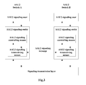
- Fig. 3 is a typical instance of AAL2 signaling completion refrence structure
- Fig. 4 is embodiment 1 of AAL2 path state synchronization flow according to the present invention.
- Fig. 5 is embodiment 2 of AAL2 path state synchronization flow according to the present invention.
- Fig. 6 is embodiment 3 of AAL2 path state synchronization flow according to the present invention.
- AAL2 swtichers A, B may each comprise AAL2 signaling user, AAL2 signaling entity, and signaling transfer layer, wherein:
- the AAL2 signaling user is an AAL2-based upper-layer signaling entity to which the AAL2 signaling entity provides corresponding services.
- the services provided by the AAL2 signaling entity to the upper-layer user signaling entity mainly comprise: establishing an AAL2 link, and releasing an AAL2 link.
- the AAL2 signaling entity may comprise AAL2 signaling controlling means and AAL2 signaling transceiving means, wherein, the AAL2 signaling controlling means mainly process call procedure regarding ALL2 connection in the switch, for example, generating, assemblying, and analyzing ALL2 signaling messages and parameters, allocating and managing resources such as bandwidth, CID, controlling call admission, selecting routes, and establishing and releasing AAL2 path connection, etc.
- a typical AAL2 path may be a VCC (virtual channel connection) between two AAL2 signaling nodes, for bearing all ATM-based load information.
- the AAL2 signaling transceiving means performs AAL2 signaling message outgoing transmission, incoming receiption, and path state maintenance, which may be implemnted by a plurality of protocol processes, for example, outgoing transmission protocol process, incoming reception protocol process, and maintenance protocol process, the above processes may be dynamically created and deleted during the call process.
- An AAL2 path state may be identified inside the switch through a plurality of manners, for example, Outgoing/Incoming Release Pending, Outgoing/ Incoming Modify Pending, etc., while from the perspective of the actual states at two ends of the path, they may be defined as "idle", "local block", and "remote block".
- the signaling transfer layer may adopt the ATM transmission mode, which provides functions of a fixed-length ATM service data unit transmission to the upper-layer AAL2 protocol entity layer, for example, cell multiplexing/ demultiplexing, generation and deletion of cell header, traffic management of cell, and cell rate adaptation, etc., and transmits ATM cells over a specific physical medium through the ATM physical layer functionality.
- the AAL2 signaling controlling means of the AAL2 switch A first performs AAL2 path state synchronization request. Specifically, it sends a path state request message to a peer AAL2 switch A of the AAL2 path.
- the request message may be an UBL (unblock request) message that comprises CEID (identifier of AAL2 connection unit) and OSAID (identifier of source signaling connection) information and the AAL2 path to which the UBL message is directed can be determined.
- the AAL2 signaling controlling means of the intermediate AAL2 switching node during the signaling transmission process, or of the AAL2 switch B as the AAL2 service endpoint (hereinafter uniformly referred to as the "AAL2 signaling node"), after receiving the request message, performs local check to the state of the designated AAL2 path and performs consistency synchronization on the AAL2 path states at two ends based on the result of check, for example, it modifies the local AAL2 path state such that it is consistent with the path state in the AAL2 switch of the requester, or notifies the AAL2 switch of the requester to modify its AAL2 path state such that it is consistent with the local AAL2 path state thereof.
- the signaling entity of AAL2 switch A as the establishment initiating end sends a UBL (unblock request) message to the peer AAL2 signaling node, i.e., switch B, and meanwhile, initiates the timer Timer_UBL, and the path state is set as "idle”.
- UBL unblock request
- the signaling entity of the peer AAL2 switch B receives the UBL message, and checks and obtains that its local AAL2 path state is "idle" based on the path identifier in the UBL message, and then sends a UBC (unblock confirmation) message to the initiating end AAL2 switch A.
- UBC unblock confirmation
- the present switch stops the timer Timer_UBL, and the path state still maintains "idle”. If the signaling entity of switch A does not receive the UBC (unblock confirmation) message sent from the signaling entity of the peer AAL2 switch during the time period of the timer Timer_UBL, it may further send a UBL (unblock request) message to the peer AAL2 switch B.
- the signaling entity of AAL2 switch A as the establishment initiating end sends a UBL (unblock request) message to the peer AAL2 signaling node, i.e., switch B, and meanwhile, initiates the timer Timer_UBL, and the path state is set as "idle”.
- UBL unblock request
- the signaling entity of the peer AAL2 switch B receives the UBL message, and obtains that its local AAL2 path state is "remote block” based on the path identifier in the UBL message, and then it resets its path state as "idle", and further sends a UBC (unblock confirmation) message to the signaling entity of initiating end AAL2 switch A.
- UBC unblock confirmation
- the present switch stops the timer Timer_UBL, and the path state still maintains "idle”. If the AAL2 switch A does not receive the UBC (unblock confirmation) message sent from the signaling entity of the peer AAL2 switch B during the time period of the timer Timer_UBL, it may further send a UBL (unblock request) message to the peer AAL2 switch B.
- the signaling entity of AAL2 switch A as the establishment initiating end sends a UBL (unblock request) message to the peer AAL2 signaling node, i.e., switch B, and meanwhile, initiates the timer Timer_UBL, and the path state is set as "idle”.
- UBL unblock request
- the signaling entity of the peer AAL2 switch B receives the UBL message for the AAL2 path, checks and obtains that its local AAL2 path state is "local block” based on the path identifier in the UBL message, and neglects the UBL message. With reference to the stipulation in section 8.2.1.2.2.1 b in ITU-T Q.2630.1, it will start the block process and send a BLO (block request) message to the peer AAL2 switch A.
- the signaling entity of initiating end AAL2 switch A when receiving the BLO (block request) message sent from the peer AAL2 switch B, stops the timer Timer_UBL, and the path state is set as "remote block", and the path will not receive a non-test type new call. Afterwards, the signaling entity of AAL2 switch A may further send a BLC (block confirmation) message to the AAL2 switch B.
- BLO block request
- BLC block confirmation
Landscapes
- Engineering & Computer Science (AREA)
- Computer Networks & Wireless Communication (AREA)
- Signal Processing (AREA)
- Data Exchanges In Wide-Area Networks (AREA)
- Telephonic Communication Services (AREA)
Abstract
Description
- The present invention relates to the field of communication technology, and in particular relates to a method and apparatus for synchronizing AAL2 path states between AAL2 signaling nodes.
- AAL2 (ATM adaptation layer type 2) protocol proposed by the ITU-T (International Telecommunication Union Telecommunication Standardization Sector) and ATM (Asynchronous Transfer Mode) Conference may effectively bear application services with low bit-rate and being sensitive to time delay and may multiplex multi-path voice and data packets over an ATM connection to improve utilization efficiency of network resources.
- ITU-T Q.2630.1 (2) AAL Type 2 Signaling Protocol- Capability Set 1 (2) is the most important protocol in the AAL2 signaling protocol. It mainly functions to establish or release AAL2 connection over a plurality of AAL2 links, allocate or release AAL2 resources, and maintain and control channels and paths, etc. This signaling protocol is widely applied between ATM switches in wideband network and mobile switches in the 3rd generation mobile communication network.
-
Fig. 1 is a basic flow of successfully establishing and releasing an ALL2 path. For the sake of illustration, the intermediate AAL2 switching nodes are not schematically shown. As an initiating end of the establishment, switch A selects an appropriate channel resource CEID (identifier of the AAL2 conneciton element), including Path and Channel, according to the destination address and the routing configuration, and sends an ERQ (connection request) message to a neighboring node switch B. The neighboring node switch B, after receiving the ERQ message, checks the validity of the CEID and whether other access conditions are satisfied. If the answer is right, it enters into an Established state and sends an ECF (establishment confirmation) message to the switch A. The switch A also enters into the Established state upon receiving the establishment confirmation message ECF. When the switch A as a release initiating end performs release, it sends a REL (release) message to the neighboring node switch B. The switch B receives the REL message, finds a protocol entity at its own end, and performs the release operation, and thereafter sends a RLC (release completed) message to the initiating end. - However, in actual application, reasons such as software failure at the switches may result in that an AAL2 path is not effectively released at one side, such that the AAL2 path states at switches A, B are inconsistent, which may lead to initial call failure over the path.
- Illustration of AAL2 call failure flow is made with reference to
figure 2 . The AAL2 path at the switch B side has been established, and its path state is local block. At this point, another corresponding end of the AAL2 path is established at switch A. Because the existing ITU-T Q.2630.1 standard does not provide relevant stipulation to synchronize states of the two ends of a newly established AAL2 path, the state of the newly established AAL2 path is idle at the switch A. - Because the state of the newly established AAL2 path is idle at the switch A, the switch A might utilize this AAL2 path to allocate resources to establish a new AAL2 call. That is, the switch A sends an ERQ (establishment request) message to the switch B to attemplt to allocate this AAL2 path resource. However, because the actual state of the AAL2 path at the switch B is local block, the switch B will reject this ERQ (establishment request) message, thereby causing call failure at this time.
- According to relevant stipulation in section 8.2.1.1.2.2 in ITU-T Q.2630.1, for switch B, if the state of AAL2 path is local block, as an input end, it needs to start the block flow upon receiving other request for establishing a new call than a test call, and sends a BLO (block request) message to the switch A that initiates the call. The switch A sends a BLC (block confirmation) to the switch B. Till now, after the intial call failure, the states at the two ends of the newly established AAL2 path will be consistent. That is, the state of the AAL2 path at the switch B is "local block" and the state of the AAL2 path at the switch A is "remote block". And then, the states of the two ends of the AAL2 path may be synchronized.
- Of course, some switches may implement a re-call attempt mechanism that is not prescribed in the ITU-T Q.2630.1 but independently implemented by switches of various manufacturers.
- The present invention aims to solve one or more of the previous technical problems and provides a technical solution of synchronizing states at two ends of a newly established AAL2 path.
- According to one aspect of the present invention, there is provided a method of synchronizing AAL2 path states between AAL2 signaling nodes, comprising: sending, by a source AAL2 signaling node, a path state request message to a target AAL2 signaling node; the target AAL2 signaling node, after receiving the request message, performing local check to the state of an AAL2 path designated by the request message and controlling consistency synchronization processing on the states of the AAL2 path at two ends based on the result of check.
- According to another aspect of the present invention, there is provided an AAL2 signaling node. The AAL2 signaling node, as a path state synchronization requesting end, comprises: sending means for sending a path state request message to a peer AAL2 signaling node; controlling means for performing consistency reset on the path state of present AAL2 signaling node based on the response message from the peer AAL2 signaling node.
- According to a further aspect of the present invention, there is provided an AAL2 signaling node. The AAL2 signaling node, as a path state synchronization requested end, comprises: receiving means for receiving a path state request message sent from a peer AAL2 signaling node; controlling means for performing locak check on the state of an AAL2 path designated in the request message and controlling consistency synchronization processing on the AAL2 path states at two ends based on the result of check.
- According to a still further aspect of the present invention, there is provided a method for synchronizing AAL2 path states in an AAL2 signaling node. The AAL2 signaling node, as a path state synchronization requesting end, sends a path state request message to the destination AAL2 signaling node; and may perform consistency reset to the path state of present AAL2 signaling node based on the response message from the destination AAL2 signaling node.
- According to a yet further aspect of the present invention, there is provided a method for synchronizing AAL2 path states in an AAL2 signaling node. The AAL2 signaling node, as a path request synchronization requested end, receives a path state request message form an AAL2 signaling node; performs local check on the state of the designated AAL2 path based on the request message and controls consistency synchronization processing on the AAL2 path states at two ends based on the result of check.
- The present invention has the following technical advantages.
- The states of the AAL2 path at two ends are synchronized before establishing the AAL2 path, such that it may avoid initial call failure incurred by inconsistent states at two ends of the AAL2 path.
- The present invention may further avoid secondary call, such that it saves switch resources, helps switches to establish more stable, reliable, and accurate state machines, and improves the success ratio of establishing an AAL2 path.
- Features, properties, and advantages of the present invention will become more apparent through the following detailed description with reference to the accompanying drawings in which like elements have the same identifiers, wherein:
-
Fig. 1 is a typical flow of successfully establishing an AAL2 call ; -
Fig. 2 is a typical flow of unsuccessfully establishing a call because of AAL2 path state inconsistency; -
Fig. 3 is a typical instance of AAL2 signaling completion refrence structure; -
Fig. 4 is embodiment 1 of AAL2 path state synchronization flow according to the present invention; -
Fig. 5 is embodiment 2 of AAL2 path state synchronization flow according to the present invention; -
Fig. 6 is embodiment 3 of AAL2 path state synchronization flow according to the present invention. - Hereinafter, the preferred embodiments of the present invention will be described in detail with reference to the accompanying drawings.
- The instance of the ALL2 signaling completion reference structure according to the present inventin is illustrated in
Fig. 3 , where AAL2 swtichers A, B, as AAL2 service endpoints, may each comprise AAL2 signaling user, AAL2 signaling entity, and signaling transfer layer, wherein: - The AAL2 signaling user is an AAL2-based upper-layer signaling entity to which the AAL2 signaling entity provides corresponding services. The services provided by the AAL2 signaling entity to the upper-layer user signaling entity mainly comprise: establishing an AAL2 link, and releasing an AAL2 link.
- The AAL2 signaling entity may comprise AAL2 signaling controlling means and AAL2 signaling transceiving means, wherein, the AAL2 signaling controlling means mainly process call procedure regarding ALL2 connection in the switch, for example, generating, assemblying, and analyzing ALL2 signaling messages and parameters, allocating and managing resources such as bandwidth, CID, controlling call admission, selecting routes, and establishing and releasing AAL2 path connection, etc. A typical AAL2 path may be a VCC (virtual channel connection) between two AAL2 signaling nodes, for bearing all ATM-based load information. The AAL2 signaling transceiving means performs AAL2 signaling message outgoing transmission, incoming receiption, and path state maintenance, which may be implemnted by a plurality of protocol processes, for example, outgoing transmission protocol process, incoming reception protocol process, and maintenance protocol process, the above processes may be dynamically created and deleted during the call process. An AAL2 path state may be identified inside the switch through a plurality of manners, for example, Outgoing/Incoming Release Pending, Outgoing/ Incoming Modify Pending, etc., while from the perspective of the actual states at two ends of the path, they may be defined as "idle", "local block", and "remote block".
- The signaling transfer layer may adopt the ATM transmission mode, which provides functions of a fixed-length ATM service data unit transmission to the upper-layer AAL2 protocol entity layer, for example, cell multiplexing/ demultiplexing, generation and deletion of cell header, traffic management of cell, and cell rate adaptation, etc., and transmits ATM cells over a specific physical medium through the ATM physical layer functionality.
- With reference to the embodiments of the present invention, before establishing an AAL2 path, the AAL2 signaling controlling means of the AAL2 switch A first performs AAL2 path state synchronization request. Specifically, it sends a path state request message to a peer AAL2 switch A of the AAL2 path. The request message may be an UBL (unblock request) message that comprises CEID (identifier of AAL2 connection unit) and OSAID (identifier of source signaling connection) information and the AAL2 path to which the UBL message is directed can be determined. The AAL2 signaling controlling means of the intermediate AAL2 switching node during the signaling transmission process, or of the AAL2 switch B as the AAL2 service endpoint (hereinafter uniformly referred to as the "AAL2 signaling node"), after receiving the request message, performs local check to the state of the designated AAL2 path and performs consistency synchronization on the AAL2 path states at two ends based on the result of check, for example, it modifies the local AAL2 path state such that it is consistent with the path state in the AAL2 switch of the requester, or notifies the AAL2 switch of the requester to modify its AAL2 path state such that it is consistent with the local AAL2 path state thereof.
- Hereinafter, the aforementioned path synchronization is further described with the AAL2 switch A as the request end with reference to the different AAL2 path states illustrated in
Figs. 4, 5 , and6 . - In embodiment 1 of the AAL2 path state synchronization flow of
Fig. 4 , in the case that the AAL2 path state of the peer is "idle", the AAL2 path state is synchronized and path is established. - Before establishing the AAL2 path, the signaling entity of AAL2 switch A as the establishment initiating end sends a UBL (unblock request) message to the peer AAL2 signaling node, i.e., switch B, and meanwhile, initiates the timer Timer_UBL, and the path state is set as "idle".
- The signaling entity of the peer AAL2 switch B receives the UBL message, and checks and obtains that its local AAL2 path state is "idle" based on the path identifier in the UBL message, and then sends a UBC (unblock confirmation) message to the initiating end AAL2 switch A.
- If the signaling entity of AAL2 switch A receives the UBC (unblock confirmation) message sent from the signaling entity of the peer AAL2 switch B during the time period of the timer Timer_UBL, then the present switch stops the timer Timer_UBL, and the path state still maintains "idle". If the signaling entity of switch A does not receive the UBC (unblock confirmation) message sent from the signaling entity of the peer AAL2 switch during the time period of the timer Timer_UBL, it may further send a UBL (unblock request) message to the peer AAL2 switch B.
- At this point, the states at two ends of the designated AAL2 path are synchronized into "idle".
- In embodiment 2 of the AAL2 path state synchronization flow of
Fig. 5 , in case that the peer AAL2 path state is "remote block", the AAL2 path state is synchronized and path is established. - Before establishing the AAL2 path, the signaling entity of AAL2 switch A as the establishment initiating end sends a UBL (unblock request) message to the peer AAL2 signaling node, i.e., switch B, and meanwhile, initiates the timer Timer_UBL, and the path state is set as "idle".
- The signaling entity of the peer AAL2 switch B receives the UBL message, and obtains that its local AAL2 path state is "remote block" based on the path identifier in the UBL message, and then it resets its path state as "idle", and further sends a UBC (unblock confirmation) message to the signaling entity of initiating end AAL2 switch A.
- If the signaling entity of AAL2 switch A receives the UBC (unblock confirmation) message sent from the peer AAL2 switch B during the time period of the timer Timer_UBL, then the present switch stops the timer Timer_UBL, and the path state still maintains "idle". If the AAL2 switch A does not receive the UBC (unblock confirmation) message sent from the signaling entity of the peer AAL2 switch B during the time period of the timer Timer_UBL, it may further send a UBL (unblock request) message to the peer AAL2 switch B.
- At this point, the states at two ends of the designated AAL2 path are synchronized into "idle".
- In embodiment 3 of the AAL2 path state synchronization flow of
Fig. 6 , in the case that the peer AAL2 path state is "local block", the AAL2 path state is synchronized and path is established. - Before establishing the AAL2 path, the signaling entity of AAL2 switch A as the establishment initiating end sends a UBL (unblock request) message to the peer AAL2 signaling node, i.e., switch B, and meanwhile, initiates the timer Timer_UBL, and the path state is set as "idle".
- The signaling entity of the peer AAL2 switch B receives the UBL message for the AAL2 path, checks and obtains that its local AAL2 path state is "local block" based on the path identifier in the UBL message, and neglects the UBL message. With reference to the stipulation in section 8.2.1.2.2.1 b in ITU-T Q.2630.1, it will start the block process and send a BLO (block request) message to the peer AAL2 switch A.
- The signaling entity of initiating end AAL2 switch A, when receiving the BLO (block request) message sent from the peer AAL2 switch B, stops the timer Timer_UBL, and the path state is set as "remote block", and the path will not receive a non-test type new call. Afterwards, the signaling entity of AAL2 switch A may further send a BLC (block confirmation) message to the AAL2 switch B.
- By far, the states at two ends of the designated AAL2 path are synchronized as "local block" and "remote block".
- Although some embodiments have been provided above to illustrate the present invention, they are not used to limit the protection scope of the present invention. Those skilled in the art may perform various modifications on the embodiments without departing from the scope and spirit of the preent invention. All such modifications fall within the scope of the present invention.
Claims (16)
- A method of synchronizing AAL2 (ATM adaptation layer type 2) path states between AAL2 signaling nodes, comprising steps of:a) sending, by a AAL2 signaling node as the synchronization requesting end, a path state request message to a peer AAL2 signaling node of an AAL2 path;b) performing, by the peer AAL2 signaling node, local check on the state of an AAL2 path designated by the request message after receiving the request message;c) controlling, by the peer AAL2 signaling node, consistency synchronization processing on the AAL2 path states at two ends based on the result of the check.
- The method according to claim 1, wherein the path state request message in step a) is an unblock request message.
- The method according to claim 1, wherein in step c), when the peer AAL2 signaling node detects that its local AAL2 path state is "idle", it confirms to the synchronization requesting end AAL2 signaling node.
- The method according to claim 1, wherein in step c), when the peer AAL2 signaling node detects that its local AAL2 path state is "peer block", it resets the local AAL2 path state as "idle" and confirms to the synchronization requesting end AAL2 signaling node.
- The method according to claim 1, wherein in step c), when the peer AAL2 signaling node detects that its local AAL2 path state is "local block", it notifies the synchronization requesting end AAL2 signaling node to reset the AAL2 path state.
- An AAL2 (ATM adaptation layer type 2) signaling node, comprising:sending means configured to send a path state request message to a peer AAL2 signaling node;controlling means configured to perform consistency reset to the path state of the present AAL2 signaling node based on a response from the peer AAL2 signaling node.
- The AAL2 signaling node according to claim 6, wherein the path state request message of the sending means is an unblock request message.
- The AAL2 signaling node according to claim 7, wherein the controlling means maintains the local AAL2 path state unchanged when the response message is an unblock confirmation message.
- The AAL2 signaling node according to claim 6, wherein the controlling means performs consistency reset to the local AAL2 path state with regard to the peer AAL2 signaling node when the response message is a block request message.
- An AAL2 (ATM adaptation layer type 2) signaling node, comprising:receiving means configured to receive a path state request message sent from an AAL2 signaling node;controlling means configured to perform local check on the state of an AAL2 path designated in the request message and control consistency synchronization processing on the AAL2 path states at two ends based on the result of the check.
- The AAL2 signaling node according to claim 10, wherein the path state request message is an unblock request message.
- The AAL2 signaling node according to claim 10, wherein the controlling means confirms to the peer AAL2 signaling node when the local AAL2 path state is "dile".
- The AAL2 signaling node according to claim 10, wherein the controlling means resets the local AAL2 path state as "idle" and confirms to the peer AAL2 signaling node when the local AAL2 path state is "peer block."
- The AAL2 signaling node according to claim 10, wherein the contolling means notifies the peer AAL2 signaling node to reset the AAL2 path state when detecting that its local AAL2 path state is "local block".
- A method of synchronizing AAL2 (ATM adaptation layer type 2) path states in an AAL2 signaling node, comprising steps of:step a), sending a path state request message to a peer AAL2 signaling node;step b), performing consistency reset to the path state of present AAL2 signaling node based on a response from the peer AAL2 signaling node.
- A method of synchronizing AAL2 (ATM adaptation layer type 2) path states in an AAL2 signaling node, comprising steps of:a2), receiving a path state request message sent from an AAL2 signaling node;b2), performing local check on a designated AAL2 path state based on the request message and controlling consistency synchronization processing on the AAL2 path states at two ends based on the result of check.
Applications Claiming Priority (2)
| Application Number | Priority Date | Filing Date | Title |
|---|---|---|---|
| CN2009100541711A CN101938753A (en) | 2009-06-30 | 2009-06-30 | Synchronization method for states of AAL2 paths and device thereof |
| PCT/CN2010/071141 WO2011000229A1 (en) | 2009-06-30 | 2010-03-19 | Method for synchronizing asynchronous transfer mode adaptation layer type 2 path state and thereof device |
Publications (3)
| Publication Number | Publication Date |
|---|---|
| EP2451117A1 true EP2451117A1 (en) | 2012-05-09 |
| EP2451117A4 EP2451117A4 (en) | 2014-07-02 |
| EP2451117B1 EP2451117B1 (en) | 2016-09-14 |
Family
ID=43391836
Family Applications (1)
| Application Number | Title | Priority Date | Filing Date |
|---|---|---|---|
| EP10793524.9A Not-in-force EP2451117B1 (en) | 2009-06-30 | 2010-03-19 | Method for synchronizing asynchronous transfer mode adaptation layer type 2 path state and thereof device |
Country Status (6)
| Country | Link |
|---|---|
| US (1) | US9054897B2 (en) |
| EP (1) | EP2451117B1 (en) |
| JP (1) | JP5501456B2 (en) |
| KR (1) | KR101302926B1 (en) |
| CN (1) | CN101938753A (en) |
| WO (1) | WO2011000229A1 (en) |
Family Cites Families (8)
| Publication number | Priority date | Publication date | Assignee | Title |
|---|---|---|---|---|
| US6031840A (en) * | 1995-12-07 | 2000-02-29 | Sprint Communications Co. L.P. | Telecommunications system |
| US6760335B1 (en) * | 2001-01-09 | 2004-07-06 | Telefonaktiebolaget Lm Ericsson (Publ) | Dynamic AAL2 path configuration in ATM system |
| JP3836009B2 (en) | 2001-10-12 | 2006-10-18 | 松下電器産業株式会社 | Communication control apparatus and connection establishment method |
| DE602004004066T2 (en) * | 2004-03-12 | 2007-08-09 | Siemens S.P.A. | Method for establishing a connection between two ALL2 end points in a communication network |
| CN100375446C (en) * | 2005-04-15 | 2008-03-12 | 中兴通讯股份有限公司 | Availability management method for asynchronous transfer mode adaptation layer 2 service channel |
| GB2435157B (en) * | 2006-02-10 | 2011-01-19 | Nokia Corp | Communicating Data to User Equipment Outside of Dedicated Channel State |
| CN101022451B (en) | 2006-02-14 | 2014-07-23 | 杭州华三通信技术有限公司 | Connection state synchronizing method in data communication and applied communication node thereof |
| CN101257438B (en) * | 2008-01-22 | 2010-07-14 | 中兴通讯股份有限公司 | Method for keeping channel occlusion state consistent across nodes |
-
2009
- 2009-06-30 CN CN2009100541711A patent/CN101938753A/en active Pending
-
2010
- 2010-03-19 EP EP10793524.9A patent/EP2451117B1/en not_active Not-in-force
- 2010-03-19 WO PCT/CN2010/071141 patent/WO2011000229A1/en not_active Ceased
- 2010-03-19 JP JP2012518006A patent/JP5501456B2/en not_active Expired - Fee Related
- 2010-03-19 US US13/376,258 patent/US9054897B2/en not_active Expired - Fee Related
- 2010-03-19 KR KR1020117031282A patent/KR101302926B1/en not_active Expired - Fee Related
Also Published As
| Publication number | Publication date |
|---|---|
| EP2451117A4 (en) | 2014-07-02 |
| WO2011000229A1 (en) | 2011-01-06 |
| EP2451117B1 (en) | 2016-09-14 |
| US20120087366A1 (en) | 2012-04-12 |
| CN101938753A (en) | 2011-01-05 |
| KR20120014222A (en) | 2012-02-16 |
| KR101302926B1 (en) | 2013-09-06 |
| JP2012531850A (en) | 2012-12-10 |
| JP5501456B2 (en) | 2014-05-21 |
| US9054897B2 (en) | 2015-06-09 |
Similar Documents
| Publication | Publication Date | Title |
|---|---|---|
| JP2000115200A (en) | Method and apparatus for reducing call setup rate in an ATM network | |
| US6760335B1 (en) | Dynamic AAL2 path configuration in ATM system | |
| US20030099192A1 (en) | Method and system for a switched virtual circuit with virtual termination | |
| EP0748544B1 (en) | Method for rerouting a packet-mode data connection | |
| US6993030B2 (en) | AAL2 negotiation procedure | |
| US7106698B1 (en) | System for triggering the control plane in an asynchronous connection-oriented transmission network | |
| US6735176B1 (en) | Dynamic bandwidth management and rerouting | |
| US9054897B2 (en) | Method and apparatus for synchronizing AAL2 path states | |
| CN100414878C (en) | Implementation method of network interconnection management based on asynchronous transfer mode | |
| TW200527927A (en) | Transport network control signalling | |
| KR100304940B1 (en) | Network making Method in Asynchronous Transfer Mode | |
| KR100941801B1 (en) | How to handle call setup related messages performed in AL2 node | |
| KR19980055541A (en) | How to set / release PVC dynamically in ATM network | |
| JPH1168782A (en) | Signaling processing device and method | |
| US7283535B2 (en) | Concentrator for user AAL2 traffic carried on UBR virtual channels | |
| JPH11284621A (en) | ATM network management device | |
| CN100393054C (en) | A system and method for realizing elastic permanent virtual connection | |
| KR100241885B1 (en) | How to Implement Soft 5C on ATM Switching Network | |
| Kasera et al. | AAL2 Signalling: A White Paper | |
| KR100296354B1 (en) | Call Processing Method in Asynchronous Transfer Mode Switch for IMT-2000 Mobile Call Processing | |
| JP3546814B2 (en) | ATM device and ATM communication network | |
| KR970002710B1 (en) | Interfacing method of atm adaptation aal and call control layer in the atm switch | |
| JPH10322361A (en) | Signaling method, switching device, storage medium, and network | |
| EP1066733A1 (en) | Dynamic bandwidth management and rerouting | |
| CN100558077C (en) | A method for realizing AAL2 intercommunication in equipment |
Legal Events
| Date | Code | Title | Description |
|---|---|---|---|
| PUAI | Public reference made under article 153(3) epc to a published international application that has entered the european phase |
Free format text: ORIGINAL CODE: 0009012 |
|
| 17P | Request for examination filed |
Effective date: 20120130 |
|
| AK | Designated contracting states |
Kind code of ref document: A1 Designated state(s): AT BE BG CH CY CZ DE DK EE ES FI FR GB GR HR HU IE IS IT LI LT LU LV MC MK MT NL NO PL PT RO SE SI SK SM TR |
|
| DAX | Request for extension of the european patent (deleted) | ||
| 111Z | Information provided on other rights and legal means of execution |
Free format text: AT BE BG CH CY CZ DE DK EE ES FI FR GB GR HR HU IE IS IT LI LT LU LV MC MK MT NL NO PL PT RO SE SI SK SM TR Effective date: 20130410 |
|
| A4 | Supplementary search report drawn up and despatched |
Effective date: 20140604 |
|
| RIC1 | Information provided on ipc code assigned before grant |
Ipc: H04L 12/70 20130101ALI20140528BHEP Ipc: H04L 12/54 20130101ALI20140528BHEP Ipc: H04L 12/24 20060101AFI20140528BHEP |
|
| RAP1 | Party data changed (applicant data changed or rights of an application transferred) |
Owner name: ALCATEL LUCENT |
|
| D11X | Information provided on other rights and legal means of execution (deleted) | ||
| 17Q | First examination report despatched |
Effective date: 20150702 |
|
| GRAP | Despatch of communication of intention to grant a patent |
Free format text: ORIGINAL CODE: EPIDOSNIGR1 |
|
| INTG | Intention to grant announced |
Effective date: 20160421 |
|
| GRAS | Grant fee paid |
Free format text: ORIGINAL CODE: EPIDOSNIGR3 |
|
| GRAA | (expected) grant |
Free format text: ORIGINAL CODE: 0009210 |
|
| AK | Designated contracting states |
Kind code of ref document: B1 Designated state(s): AT BE BG CH CY CZ DE DK EE ES FI FR GB GR HR HU IE IS IT LI LT LU LV MC MK MT NL NO PL PT RO SE SI SK SM TR |
|
| REG | Reference to a national code |
Ref country code: GB Ref legal event code: FG4D |
|
| REG | Reference to a national code |
Ref country code: CH Ref legal event code: EP |
|
| REG | Reference to a national code |
Ref country code: IE Ref legal event code: FG4D |
|
| REG | Reference to a national code |
Ref country code: AT Ref legal event code: REF Ref document number: 830035 Country of ref document: AT Kind code of ref document: T Effective date: 20161015 |
|
| REG | Reference to a national code |
Ref country code: DE Ref legal event code: R096 Ref document number: 602010036452 Country of ref document: DE |
|
| REG | Reference to a national code |
Ref country code: LT Ref legal event code: MG4D |
|
| REG | Reference to a national code |
Ref country code: NL Ref legal event code: MP Effective date: 20160914 |
|
| PG25 | Lapsed in a contracting state [announced via postgrant information from national office to epo] |
Ref country code: FI Free format text: LAPSE BECAUSE OF FAILURE TO SUBMIT A TRANSLATION OF THE DESCRIPTION OR TO PAY THE FEE WITHIN THE PRESCRIBED TIME-LIMIT Effective date: 20160914 Ref country code: LT Free format text: LAPSE BECAUSE OF FAILURE TO SUBMIT A TRANSLATION OF THE DESCRIPTION OR TO PAY THE FEE WITHIN THE PRESCRIBED TIME-LIMIT Effective date: 20160914 Ref country code: HR Free format text: LAPSE BECAUSE OF FAILURE TO SUBMIT A TRANSLATION OF THE DESCRIPTION OR TO PAY THE FEE WITHIN THE PRESCRIBED TIME-LIMIT Effective date: 20160914 Ref country code: NO Free format text: LAPSE BECAUSE OF FAILURE TO SUBMIT A TRANSLATION OF THE DESCRIPTION OR TO PAY THE FEE WITHIN THE PRESCRIBED TIME-LIMIT Effective date: 20161214 |
|
| REG | Reference to a national code |
Ref country code: AT Ref legal event code: MK05 Ref document number: 830035 Country of ref document: AT Kind code of ref document: T Effective date: 20160914 |
|
| PG25 | Lapsed in a contracting state [announced via postgrant information from national office to epo] |
Ref country code: NL Free format text: LAPSE BECAUSE OF FAILURE TO SUBMIT A TRANSLATION OF THE DESCRIPTION OR TO PAY THE FEE WITHIN THE PRESCRIBED TIME-LIMIT Effective date: 20160914 Ref country code: LV Free format text: LAPSE BECAUSE OF FAILURE TO SUBMIT A TRANSLATION OF THE DESCRIPTION OR TO PAY THE FEE WITHIN THE PRESCRIBED TIME-LIMIT Effective date: 20160914 Ref country code: GR Free format text: LAPSE BECAUSE OF FAILURE TO SUBMIT A TRANSLATION OF THE DESCRIPTION OR TO PAY THE FEE WITHIN THE PRESCRIBED TIME-LIMIT Effective date: 20161215 Ref country code: SE Free format text: LAPSE BECAUSE OF FAILURE TO SUBMIT A TRANSLATION OF THE DESCRIPTION OR TO PAY THE FEE WITHIN THE PRESCRIBED TIME-LIMIT Effective date: 20160914 |
|
| PG25 | Lapsed in a contracting state [announced via postgrant information from national office to epo] |
Ref country code: EE Free format text: LAPSE BECAUSE OF FAILURE TO SUBMIT A TRANSLATION OF THE DESCRIPTION OR TO PAY THE FEE WITHIN THE PRESCRIBED TIME-LIMIT Effective date: 20160914 Ref country code: RO Free format text: LAPSE BECAUSE OF FAILURE TO SUBMIT A TRANSLATION OF THE DESCRIPTION OR TO PAY THE FEE WITHIN THE PRESCRIBED TIME-LIMIT Effective date: 20160914 |
|
| PG25 | Lapsed in a contracting state [announced via postgrant information from national office to epo] |
Ref country code: IS Free format text: LAPSE BECAUSE OF FAILURE TO SUBMIT A TRANSLATION OF THE DESCRIPTION OR TO PAY THE FEE WITHIN THE PRESCRIBED TIME-LIMIT Effective date: 20170114 Ref country code: PT Free format text: LAPSE BECAUSE OF FAILURE TO SUBMIT A TRANSLATION OF THE DESCRIPTION OR TO PAY THE FEE WITHIN THE PRESCRIBED TIME-LIMIT Effective date: 20170116 Ref country code: ES Free format text: LAPSE BECAUSE OF FAILURE TO SUBMIT A TRANSLATION OF THE DESCRIPTION OR TO PAY THE FEE WITHIN THE PRESCRIBED TIME-LIMIT Effective date: 20160914 Ref country code: CZ Free format text: LAPSE BECAUSE OF FAILURE TO SUBMIT A TRANSLATION OF THE DESCRIPTION OR TO PAY THE FEE WITHIN THE PRESCRIBED TIME-LIMIT Effective date: 20160914 Ref country code: BE Free format text: LAPSE BECAUSE OF FAILURE TO SUBMIT A TRANSLATION OF THE DESCRIPTION OR TO PAY THE FEE WITHIN THE PRESCRIBED TIME-LIMIT Effective date: 20160914 Ref country code: BG Free format text: LAPSE BECAUSE OF FAILURE TO SUBMIT A TRANSLATION OF THE DESCRIPTION OR TO PAY THE FEE WITHIN THE PRESCRIBED TIME-LIMIT Effective date: 20161214 Ref country code: SM Free format text: LAPSE BECAUSE OF FAILURE TO SUBMIT A TRANSLATION OF THE DESCRIPTION OR TO PAY THE FEE WITHIN THE PRESCRIBED TIME-LIMIT Effective date: 20160914 Ref country code: SK Free format text: LAPSE BECAUSE OF FAILURE TO SUBMIT A TRANSLATION OF THE DESCRIPTION OR TO PAY THE FEE WITHIN THE PRESCRIBED TIME-LIMIT Effective date: 20160914 Ref country code: AT Free format text: LAPSE BECAUSE OF FAILURE TO SUBMIT A TRANSLATION OF THE DESCRIPTION OR TO PAY THE FEE WITHIN THE PRESCRIBED TIME-LIMIT Effective date: 20160914 Ref country code: PL Free format text: LAPSE BECAUSE OF FAILURE TO SUBMIT A TRANSLATION OF THE DESCRIPTION OR TO PAY THE FEE WITHIN THE PRESCRIBED TIME-LIMIT Effective date: 20160914 |
|
| REG | Reference to a national code |
Ref country code: DE Ref legal event code: R097 Ref document number: 602010036452 Country of ref document: DE |
|
| PG25 | Lapsed in a contracting state [announced via postgrant information from national office to epo] |
Ref country code: IT Free format text: LAPSE BECAUSE OF FAILURE TO SUBMIT A TRANSLATION OF THE DESCRIPTION OR TO PAY THE FEE WITHIN THE PRESCRIBED TIME-LIMIT Effective date: 20160914 |
|
| PLBE | No opposition filed within time limit |
Free format text: ORIGINAL CODE: 0009261 |
|
| STAA | Information on the status of an ep patent application or granted ep patent |
Free format text: STATUS: NO OPPOSITION FILED WITHIN TIME LIMIT |
|
| PG25 | Lapsed in a contracting state [announced via postgrant information from national office to epo] |
Ref country code: DK Free format text: LAPSE BECAUSE OF FAILURE TO SUBMIT A TRANSLATION OF THE DESCRIPTION OR TO PAY THE FEE WITHIN THE PRESCRIBED TIME-LIMIT Effective date: 20160914 |
|
| 26N | No opposition filed |
Effective date: 20170615 |
|
| REG | Reference to a national code |
Ref country code: DE Ref legal event code: R119 Ref document number: 602010036452 Country of ref document: DE |
|
| REG | Reference to a national code |
Ref country code: CH Ref legal event code: PL |
|
| GBPC | Gb: european patent ceased through non-payment of renewal fee |
Effective date: 20170319 |
|
| PG25 | Lapsed in a contracting state [announced via postgrant information from national office to epo] |
Ref country code: MC Free format text: LAPSE BECAUSE OF FAILURE TO SUBMIT A TRANSLATION OF THE DESCRIPTION OR TO PAY THE FEE WITHIN THE PRESCRIBED TIME-LIMIT Effective date: 20160914 Ref country code: SI Free format text: LAPSE BECAUSE OF FAILURE TO SUBMIT A TRANSLATION OF THE DESCRIPTION OR TO PAY THE FEE WITHIN THE PRESCRIBED TIME-LIMIT Effective date: 20160914 |
|
| REG | Reference to a national code |
Ref country code: IE Ref legal event code: MM4A |
|
| REG | Reference to a national code |
Ref country code: FR Ref legal event code: ST Effective date: 20171130 |
|
| PG25 | Lapsed in a contracting state [announced via postgrant information from national office to epo] |
Ref country code: LU Free format text: LAPSE BECAUSE OF NON-PAYMENT OF DUE FEES Effective date: 20170319 Ref country code: FR Free format text: LAPSE BECAUSE OF NON-PAYMENT OF DUE FEES Effective date: 20170331 Ref country code: DE Free format text: LAPSE BECAUSE OF NON-PAYMENT OF DUE FEES Effective date: 20171003 |
|
| PG25 | Lapsed in a contracting state [announced via postgrant information from national office to epo] |
Ref country code: GB Free format text: LAPSE BECAUSE OF NON-PAYMENT OF DUE FEES Effective date: 20170319 Ref country code: LI Free format text: LAPSE BECAUSE OF NON-PAYMENT OF DUE FEES Effective date: 20170331 Ref country code: CH Free format text: LAPSE BECAUSE OF NON-PAYMENT OF DUE FEES Effective date: 20170331 Ref country code: IE Free format text: LAPSE BECAUSE OF NON-PAYMENT OF DUE FEES Effective date: 20170319 |
|
| PG25 | Lapsed in a contracting state [announced via postgrant information from national office to epo] |
Ref country code: MT Free format text: LAPSE BECAUSE OF NON-PAYMENT OF DUE FEES Effective date: 20170319 |
|
| PG25 | Lapsed in a contracting state [announced via postgrant information from national office to epo] |
Ref country code: HU Free format text: LAPSE BECAUSE OF FAILURE TO SUBMIT A TRANSLATION OF THE DESCRIPTION OR TO PAY THE FEE WITHIN THE PRESCRIBED TIME-LIMIT; INVALID AB INITIO Effective date: 20100319 |
|
| PG25 | Lapsed in a contracting state [announced via postgrant information from national office to epo] |
Ref country code: CY Free format text: LAPSE BECAUSE OF NON-PAYMENT OF DUE FEES Effective date: 20160914 |
|
| PG25 | Lapsed in a contracting state [announced via postgrant information from national office to epo] |
Ref country code: MK Free format text: LAPSE BECAUSE OF FAILURE TO SUBMIT A TRANSLATION OF THE DESCRIPTION OR TO PAY THE FEE WITHIN THE PRESCRIBED TIME-LIMIT Effective date: 20160914 |
|
| PG25 | Lapsed in a contracting state [announced via postgrant information from national office to epo] |
Ref country code: TR Free format text: LAPSE BECAUSE OF FAILURE TO SUBMIT A TRANSLATION OF THE DESCRIPTION OR TO PAY THE FEE WITHIN THE PRESCRIBED TIME-LIMIT Effective date: 20160914 |