EP2451052A2 - Electric machine, insulating cap and method for realising an insulating cap - Google Patents
Electric machine, insulating cap and method for realising an insulating cap Download PDFInfo
- Publication number
- EP2451052A2 EP2451052A2 EP20110186100 EP11186100A EP2451052A2 EP 2451052 A2 EP2451052 A2 EP 2451052A2 EP 20110186100 EP20110186100 EP 20110186100 EP 11186100 A EP11186100 A EP 11186100A EP 2451052 A2 EP2451052 A2 EP 2451052A2
- Authority
- EP
- European Patent Office
- Prior art keywords
- electric machine
- seat
- insulating cap
- cap
- shaped
- Prior art date
- Legal status (The legal status is an assumption and is not a legal conclusion. Google has not performed a legal analysis and makes no representation as to the accuracy of the status listed.)
- Withdrawn
Links
Images


Classifications
-
- H—ELECTRICITY
- H02—GENERATION; CONVERSION OR DISTRIBUTION OF ELECTRIC POWER
- H02K—DYNAMO-ELECTRIC MACHINES
- H02K3/00—Details of windings
- H02K3/32—Windings characterised by the shape, form or construction of the insulation
- H02K3/38—Windings characterised by the shape, form or construction of the insulation around winding heads, equalising connectors, or connections thereto
-
- H—ELECTRICITY
- H02—GENERATION; CONVERSION OR DISTRIBUTION OF ELECTRIC POWER
- H02K—DYNAMO-ELECTRIC MACHINES
- H02K15/00—Processes or apparatus specially adapted for manufacturing, assembling, maintaining or repairing of dynamo-electric machines
- H02K15/10—Applying solid insulation to windings, stators or rotors, e.g. applying insulating tapes
- H02K15/105—Applying solid insulation to windings, stators or rotors, e.g. applying insulating tapes to the windings
-
- Y—GENERAL TAGGING OF NEW TECHNOLOGICAL DEVELOPMENTS; GENERAL TAGGING OF CROSS-SECTIONAL TECHNOLOGIES SPANNING OVER SEVERAL SECTIONS OF THE IPC; TECHNICAL SUBJECTS COVERED BY FORMER USPC CROSS-REFERENCE ART COLLECTIONS [XRACs] AND DIGESTS
- Y10—TECHNICAL SUBJECTS COVERED BY FORMER USPC
- Y10T—TECHNICAL SUBJECTS COVERED BY FORMER US CLASSIFICATION
- Y10T29/00—Metal working
- Y10T29/49—Method of mechanical manufacture
- Y10T29/49002—Electrical device making
- Y10T29/49227—Insulator making
Definitions
- the present invention relates to an electric machine, an insulating cap and a method for realising an insulating cap.
- Figure 1 shows a traditional connection between windings 2 of a stator of an electric machine such as a generator and phase connections 4 (phase rings).
- This connection typically comprises a conductive element 3 brazed at one side to the winding 2 and at the other side to the phase connection 4.
- an insulating cap 5 is provided above the winding 2 end, conductive element 3 and phase connections 4 end to insulate and protect the components housed therein.
- traditional caps 5 are made is two elements; a first element 6 that houses the winding 2 end and the greatest part of the conductive element 3, and a second element 7 that envelopes the phase connection 4 end and has its ends that overlap the borders of the first element 6 at the zones 8.
- Also putty 9 is provided within the first and second elements 6, 7 to mechanically fix the cap 5 and electrically insulate the components housed therein.
- the minimum distance between two adjacent caps 5 must be large enough to avoid discharges (this is the so called electric distance that depends on the materials, voltage, etc).
- An aspect therefore includes providing an electric machine, an insulating cap and a method addressing the aforementioned problems of the known art.
- An additional aspect is to provide a machine, a cap and a method allowing an increased distance between adjacent caps, in order to achieve more design flexibility (for example number of slots or voltage) or improved upgrade possibilities.
- Another aspect is to provide a machine, a cap and a method, which permit a quicker assembling.
- the cap is very robust (more than traditional caps), this allowing a simpler wedging between the caps than with traditional caps.
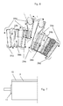
- the electric machine has a stator 10 with windings 2 and a rotor 11.
- the windings 2 are connected to phase connections 4 via the conductive elements 3.
- an insulating cap 5 protecting the reciprocally connected portions of the phase connections 4 and windings 2 is provided.
- reference 5a designates the cap provided to insulate the connection between an upper winding within a slot and a phase connection 4; likewise 5b designates the cap provided to insulate the connection between a bottom winding within the slot and a phase connection 4.
- Each insulating cap 5 has a box-shaped body 15 with an opening 16 for the introduction of a winding 2 within it.
- the body 15 defines a seat 17 housing the phase connection 4; this seat 17 is realised in one piece with the body 15.
- the seat 15 is U-shaped, with the side walls 19 of the U-shaped seat 15 facing away from the body 15.
- the seat 17 and the cap 15 are filled with putty 9.
- a conductive element 3 is provided that is fully housed within the cap 5.
- caps 18 covering, protecting and insulating the reciprocally connected ends of the windings are shown.
- the cap 5 Before it is mounted on the electric machine, the cap 5 has the body 15 with the seat 17 closed by the walls 22, 23 depicted in dashed lines.
- This structure is used to test the electrical properties of the cap; it is clear that since only one part must be tested for each cap (instead of two like with traditional caps) these tests are quicker.
- Tapes 24a, 24b can be provided; these tapes can be wrapped in the circumferential direction (arrows 24a) and in axial direction (arrows 24b). When provided, these tapes do not substantially alter the distance between adjacent caps 5 (i.e. they are very thin).
- the present invention also relates to a method for realising an insulating cap 5 for a rotating electric machine comprising the steps of cutting a box-shaped body 15 and removing at least a portion of a first wall 22 and define a first open surface 25 delimiting the body 15.
- At least a second portion of a second wall 23 that is adjacent to the first open surface 25 is cut, to define a second open surface 26 adjacent to the first open surface 25 and delimiting the body 15; the open surfaces 25, 26 allow a U-shaped seat 17 to be defined.
Landscapes
- Engineering & Computer Science (AREA)
- Power Engineering (AREA)
- Manufacturing & Machinery (AREA)
- Insulation, Fastening Of Motor, Generator Windings (AREA)
- Manufacture Of Motors, Generators (AREA)
Abstract
Description
- The present invention relates to an electric machine, an insulating cap and a method for realising an insulating cap.
-
Figure 1 shows a traditional connection betweenwindings 2 of a stator of an electric machine such as a generator and phase connections 4 (phase rings). - This connection typically comprises a
conductive element 3 brazed at one side to the winding 2 and at the other side to thephase connection 4. - Above the winding 2 end,
conductive element 3 andphase connections 4 end aninsulating cap 5 is provided to insulate and protect the components housed therein. - As shown,
traditional caps 5 are made is two elements; afirst element 6 that houses the winding 2 end and the greatest part of theconductive element 3, and asecond element 7 that envelopes thephase connection 4 end and has its ends that overlap the borders of thefirst element 6 at thezones 8. - Also
putty 9 is provided within the first andsecond elements cap 5 and electrically insulate the components housed therein. - These
caps 5 proved to be very efficient and provide an excellent insulation, but in some cases their use could be troubling. - In fact, the minimum distance between two
adjacent caps 5 must be large enough to avoid discharges (this is the so called electric distance that depends on the materials, voltage, etc). - With the described traditional caps the minimum distance is much smaller than what possible, because of the overlapping of the
second parts 7 on thefirst parts 6 of thecaps 5. This causes large constrains in the machine design (for example with reference to the number of slots housing the windings) or maximum voltage achievable. - In addition, upgrade of a machine such as an electric generator (by increasing the operating voltage) could not be possible, because the upgraded voltage could be too high for the actual distances between
adjacent caps 5. - Moreover, assembling of the two
pieces caps 5 and at the same time the provision of putty is typically very time consuming. - An aspect therefore includes providing an electric machine, an insulating cap and a method addressing the aforementioned problems of the known art.
- An additional aspect is to provide a machine, a cap and a method allowing an increased distance between adjacent caps, in order to achieve more design flexibility (for example number of slots or voltage) or improved upgrade possibilities.
- Another aspect is to provide a machine, a cap and a method, which permit a quicker assembling.
- These and further aspects are attained according to the invention by providing a machine, a cap and a method in accordance with the accompanying claims.
- Advantageously, the cap is very robust (more than traditional caps), this allowing a simpler wedging between the caps than with traditional caps.
- Further characteristics and advantages of the invention will be more apparent from the description of a preferred but non-exclusive embodiment of the machine, cap and method illustrated by way of non-limiting example in the accompanying drawings, in which:
-
Figure 1 is a top view of traditional caps; -
Figures 2 and 3 respectively show a perspective view and a top view of caps in an embodiment of the invention; -
Figures 4 and 5 show respectively a bottom view and a cross section through line V-V offigure 4 of a cap in an embodiment of the invention; in these figures the cap ready to be installed on an electric machine is depicted in solid line and portions of the cap to be cut and removed before it is assembled on the electric machine are depicted in dashed line; -
Figure 6 schematically shows a top view of the caps wrapped with a tape; and -
Figure 7 schematically shows a portion of an electric machine such as an electric generator. - In
figures 1 through 7 like reference numerals designate identical or corresponding parts throughout the several views. - The electric machine has a
stator 10 withwindings 2 and arotor 11. Thewindings 2 are connected tophase connections 4 via theconductive elements 3. - With particular reference to
figure 2 and 3 , aninsulating cap 5 protecting the reciprocally connected portions of thephase connections 4 andwindings 2 is provided. - In
particular reference 5a designates the cap provided to insulate the connection between an upper winding within a slot and aphase connection 4; likewise 5b designates the cap provided to insulate the connection between a bottom winding within the slot and aphase connection 4. - Each insulating
cap 5 has a box-shaped body 15 with anopening 16 for the introduction of a winding 2 within it. - In addition, the
body 15 defines aseat 17 housing thephase connection 4; thisseat 17 is realised in one piece with thebody 15. - In particular, the
seat 15 is U-shaped, with theside walls 19 of the U-shapedseat 15 facing away from thebody 15. - The
seat 17 and thecap 15 are filled withputty 9. - Advantageously, between the
winding 2 and thephase connection 4, aconductive element 3 is provided that is fully housed within thecap 5. - In
figures 2 and 3 also thecaps 18 covering, protecting and insulating the reciprocally connected ends of the windings are shown. - With reference to
figures 4 and 5 , before it is mounted on the electric machine, thecap 5 has thebody 15 with theseat 17 closed by thewalls - This structure is used to test the electrical properties of the cap; it is clear that since only one part must be tested for each cap (instead of two like with traditional caps) these tests are quicker.
- Then the
walls seat 17 and thecaps 5 are mounted by filling them with theputty 9 and place above the winding 2 end,conductive element 3 andphase connection 4 end. It is clear that since only one element must be cut and mounted, also assembling is quicker than with traditional caps. - In addition, as clearly shown in
figure 3 , since the caps have no overlapping zones causing thicker portions, also the minimum distance is sensibly increased, allowing design flexibility, voltage increase and more upgrade possibilities. -
Tapes arrows 24a) and in axial direction (arrows 24b). When provided, these tapes do not substantially alter the distance between adjacent caps 5 (i.e. they are very thin). - The present invention also relates to a method for realising an
insulating cap 5 for a rotating electric machine comprising the steps of cutting a box-shaped body 15 and removing at least a portion of afirst wall 22 and define a firstopen surface 25 delimiting thebody 15. - Advantageously, also at least a second portion of a
second wall 23 that is adjacent to the firstopen surface 25 is cut, to define a secondopen surface 26 adjacent to the firstopen surface 25 and delimiting thebody 15; theopen surfaces U-shaped seat 17 to be defined. - Naturally the features described may be independently provided from one another.
- In practice the materials used and the dimensions can be chosen at will according to requirements and to the state of the art.
-
- 2
- windings
- 3
- conductive element
- 4
- phase connection
- 5, 5a, 5b
- insulating cap
- 6
- first element of 5
- 7
- second element of 5
- 8
- zone of 5
- 9
- putty
- 10
- stator
- 11
- rotor
- 15
- body
- 16
- opening
- 17
- seat
- 18
- cap
- 19
- walls of 17
- 22
- wall of 15 to be removed
- 23
- wall of 15 to be removed
- 24a, 24b
- tape
- 25
- open surface of 15
- 26
- open surface of 15
Claims (8)
- Electric machine having a stator (10) with windings (2) connected to phase connections (4), wherein an insulating cap (5) protecting the reciprocally connected portions of the phase connections (4) and windings (2) is provided, the insulating cap (5) having a box-shaped body (15) with an opening (16) for the introduction of a winding (2) within it, characterised in that the body (15) defines a seat (17) housing the phase connection (4), and in that the seat (17) is realised in one piece with the body (15).
- Electric machine according to claim 1, characterised in that the seat (17) is U-shaped, wherein the side walls (19) of the U-shaped seat (17) face away from the body (15).
- Electric machine according to claim 2, characterised in that the seat (17) is filled with putty (9).
- Electric machine according to claim 2, characterised in that the cap (5) is filled with putty (9) .
- Electric machine according to claim 2, characterised in that between the winding (2) and the phase connection (4) a conductive element (3) is provided.
- Electric machine according to claim 5, characterised in that the conductive element (3) is fully housed within the cap (5).
- Insulating cap (5) for a rotating electric machine having a box-shaped body (15) with at least an opening (16), characterised in that the body (15) defines a seat (17) that is realised in one piece with the body (15), and in that the seat (17) is U-shaped, wherein the side walls (19) of the U-shaped seat (17) face away from the body (15).
- Method for realising an insulating cap (5) for a rotating electric machine comprising the steps of cutting a box-shaped body (15) and removing at least a portion of a first wall (22) and define a first open surface (25) delimiting the body (15), characterised by cutting at least a second portion of a second wall (23) that is adjacent to the first open surface (25) to define a second open surface (26) adjacent to the first open surface (25) and delimiting the body (15).
Priority Applications (1)
| Application Number | Priority Date | Filing Date | Title |
|---|---|---|---|
| EP20110186100 EP2451052A3 (en) | 2010-11-09 | 2011-10-21 | Electric machine, insulating cap and method for realising an insulating cap |
Applications Claiming Priority (2)
| Application Number | Priority Date | Filing Date | Title |
|---|---|---|---|
| EP10461533 | 2010-11-09 | ||
| EP20110186100 EP2451052A3 (en) | 2010-11-09 | 2011-10-21 | Electric machine, insulating cap and method for realising an insulating cap |
Publications (2)
| Publication Number | Publication Date |
|---|---|
| EP2451052A2 true EP2451052A2 (en) | 2012-05-09 |
| EP2451052A3 EP2451052A3 (en) | 2014-02-26 |
Family
ID=43455062
Family Applications (1)
| Application Number | Title | Priority Date | Filing Date |
|---|---|---|---|
| EP20110186100 Withdrawn EP2451052A3 (en) | 2010-11-09 | 2011-10-21 | Electric machine, insulating cap and method for realising an insulating cap |
Country Status (3)
| Country | Link |
|---|---|
| US (1) | US9118233B2 (en) |
| EP (1) | EP2451052A3 (en) |
| CN (1) | CN102570675B (en) |
Cited By (1)
| Publication number | Priority date | Publication date | Assignee | Title |
|---|---|---|---|---|
| CN103546000A (en) * | 2013-10-29 | 2014-01-29 | 上海电气电站设备有限公司 | Epoxy potting method for insulation box on end portion of electric generator |
Citations (1)
| Publication number | Priority date | Publication date | Assignee | Title |
|---|---|---|---|---|
| WO1985004532A1 (en) * | 1984-04-02 | 1985-10-10 | General Electric Company | Conductor insulating method and apparatus |
Family Cites Families (19)
| Publication number | Priority date | Publication date | Assignee | Title |
|---|---|---|---|---|
| CH507609A (en) * | 1969-10-25 | 1971-05-15 | Bbc Brown Boveri & Cie | Process for the production of soldered connections on end connections of large AC machines |
| US3978359A (en) * | 1974-10-30 | 1976-08-31 | Westinghouse Electric Corporation | Coil end insulation for dynamoelectric machines |
| DE2836230C2 (en) * | 1978-08-17 | 1982-10-28 | Siemens AG, 1000 Berlin und 8000 München | Method for isolating the soldered end connections of the stator winding of an electrical machine |
| JPS5678343A (en) * | 1979-11-29 | 1981-06-27 | Matsushita Electric Ind Co Ltd | Resin molded motor |
| US4385254A (en) * | 1981-05-27 | 1983-05-24 | Vakser Boris D | Electric-machine stator bar winding |
| US4768982A (en) * | 1987-01-15 | 1988-09-06 | Siemens Energy And Automation, Inc. | Bus bar stab insulator shroud |
| GB2225672B (en) * | 1988-09-22 | 1992-10-07 | Johnson Electric Ind Mfg | Splashproof cover for an electric motor |
| US5093598A (en) * | 1989-07-28 | 1992-03-03 | Westinghouse Electric Corp. | Semiconductor insulation layer for stator coil connections |
| DE3935299A1 (en) * | 1989-10-24 | 1991-04-25 | Bosch Gmbh Robert | COATING FOR ELECTRICAL MACHINES |
| JP3020119B2 (en) * | 1991-03-19 | 2000-03-15 | 工業技術院長 | 2-furylacrylic acid disubstituted anilide compound and organic nonlinear optical material |
| US5142182A (en) * | 1991-06-14 | 1992-08-25 | General Electric Company | Adjustable width caps for insulating series loops on bar wound armatures in electrical systems |
| DE4205168C1 (en) * | 1992-02-20 | 1993-03-18 | Vem-Antriebstechnik Ag Sachsenwerk Dresden, O-8017 Dresden, De | |
| DE4237079C2 (en) * | 1992-11-03 | 1996-10-02 | Abb Patent Gmbh | Electrical machine |
| US5334897A (en) * | 1993-05-24 | 1994-08-02 | North American Philips Corporation | Electric motor with encased housing |
| DE19538631C1 (en) * | 1995-10-17 | 1997-01-30 | Vem Elektroantriebe Gmbh | Insulation cover for electrical machine winding rod connections - has linear positioning beads or grooves and acts as mould for resin compound enclosing winding rod connection conductor insulation. |
| EP1815578A1 (en) * | 2004-11-24 | 2007-08-08 | Alstom Technology Ltd | Cover cap |
| JP2006211810A (en) * | 2005-01-27 | 2006-08-10 | Denso Corp | Segment-connected rotary electric machine |
| CH698012B1 (en) * | 2006-01-24 | 2009-04-30 | Alstom Technology Ltd | A rotating electric machine as well as methods for producing such a machine. |
| US7690933B1 (en) * | 2009-03-26 | 2010-04-06 | Sioux Valley Energy | Loadbreak electrical connector cover and method of use for preventing arcing during electrical system repairs |
-
2011
- 2011-10-21 EP EP20110186100 patent/EP2451052A3/en not_active Withdrawn
- 2011-11-07 US US13/290,757 patent/US9118233B2/en active Active
- 2011-11-09 CN CN201110359306.2A patent/CN102570675B/en active Active
Patent Citations (1)
| Publication number | Priority date | Publication date | Assignee | Title |
|---|---|---|---|---|
| WO1985004532A1 (en) * | 1984-04-02 | 1985-10-10 | General Electric Company | Conductor insulating method and apparatus |
Cited By (1)
| Publication number | Priority date | Publication date | Assignee | Title |
|---|---|---|---|---|
| CN103546000A (en) * | 2013-10-29 | 2014-01-29 | 上海电气电站设备有限公司 | Epoxy potting method for insulation box on end portion of electric generator |
Also Published As
| Publication number | Publication date |
|---|---|
| US20120112583A1 (en) | 2012-05-10 |
| EP2451052A3 (en) | 2014-02-26 |
| US9118233B2 (en) | 2015-08-25 |
| CN102570675A (en) | 2012-07-11 |
| CN102570675B (en) | 2016-09-07 |
Similar Documents
| Publication | Publication Date | Title |
|---|---|---|
| KR102101385B1 (en) | Brushless motor | |
| CA1254936A (en) | High voltage dynamoelectric machine with selectively increased coil turn-to-turn insulation strength | |
| JP5682603B2 (en) | Rotating electrical machine stator for vehicles | |
| CN108808898B (en) | Stator and rotary transformer | |
| JP5045909B2 (en) | Lamination | |
| CN112673553B (en) | Rotating electric machine, stator of rotating electric machine and method of manufacturing rotating electric machine | |
| CN105191074B (en) | It is provided with the motor and respective attenuation device for the attenuator mechanically against vibration stress | |
| JP6979464B2 (en) | Rotating machine stator | |
| US12068654B2 (en) | Stator for an electric machine | |
| US20170141635A1 (en) | Stator for electric rotary machine | |
| EP3557733A1 (en) | Coil formation in an electric machine with concentrated windings | |
| CN107404172B (en) | Insulating member for motor | |
| KR20160116568A (en) | Motor unit hving insulation member | |
| EP3713052B1 (en) | Potting and insulation for a concentrated coil soil stator | |
| CN107302274B (en) | Stator of motor | |
| JP2009089584A (en) | Motor | |
| CN108370185B (en) | Stator and rotating electric machine | |
| CN105305687A (en) | Device for accommodating electrical wiring, electrical machine and manufacturing method of electrical wiring | |
| US4724600A (en) | Method of making a high voltage dynamoelectric machine with selectively increased coil turn-to-turn insulation strength | |
| US9118233B2 (en) | Electric machine, insulating cap and method for forming an insulating cap | |
| US9018818B2 (en) | Insulating cap for an end winding of an electrical machine working at high voltage and machine having such an insulating cap | |
| US20130140935A1 (en) | Slot Liner and Interphase Insulator Combination | |
| CN109672275B (en) | Stator structure and rotary transformer | |
| JP2009089493A (en) | Motor | |
| EP2950424A1 (en) | Chamber for conductors of electric machines |
Legal Events
| Date | Code | Title | Description |
|---|---|---|---|
| PUAI | Public reference made under article 153(3) epc to a published international application that has entered the european phase |
Free format text: ORIGINAL CODE: 0009012 |
|
| AK | Designated contracting states |
Kind code of ref document: A2 Designated state(s): AL AT BE BG CH CY CZ DE DK EE ES FI FR GB GR HR HU IE IS IT LI LT LU LV MC MK MT NL NO PL PT RO RS SE SI SK SM TR |
|
| AX | Request for extension of the european patent |
Extension state: BA ME |
|
| PUAL | Search report despatched |
Free format text: ORIGINAL CODE: 0009013 |
|
| AK | Designated contracting states |
Kind code of ref document: A3 Designated state(s): AL AT BE BG CH CY CZ DE DK EE ES FI FR GB GR HR HU IE IS IT LI LT LU LV MC MK MT NL NO PL PT RO RS SE SI SK SM TR |
|
| AX | Request for extension of the european patent |
Extension state: BA ME |
|
| RIC1 | Information provided on ipc code assigned before grant |
Ipc: H02K 15/10 20060101ALI20140117BHEP Ipc: H02K 3/38 20060101AFI20140117BHEP Ipc: H02K 5/08 20060101ALI20140117BHEP |
|
| 17P | Request for examination filed |
Effective date: 20140312 |
|
| RBV | Designated contracting states (corrected) |
Designated state(s): AL AT BE BG CH CY CZ DE DK EE ES FI FR GB GR HR HU IE IS IT LI LT LU LV MC MK MT NL NO PL PT RO RS SE SI SK SM TR |
|
| 17Q | First examination report despatched |
Effective date: 20160617 |
|
| RAP1 | Party data changed (applicant data changed or rights of an application transferred) |
Owner name: GENERAL ELECTRIC TECHNOLOGY GMBH |
|
| GRAP | Despatch of communication of intention to grant a patent |
Free format text: ORIGINAL CODE: EPIDOSNIGR1 |
|
| INTG | Intention to grant announced |
Effective date: 20170220 |
|
| STAA | Information on the status of an ep patent application or granted ep patent |
Free format text: STATUS: THE APPLICATION IS DEEMED TO BE WITHDRAWN |
|
| 18D | Application deemed to be withdrawn |
Effective date: 20170704 |