EP2451040A1 - Device for eliminating a dc current component circulating in a monophasic electrical grid - Google Patents
Device for eliminating a dc current component circulating in a monophasic electrical grid Download PDFInfo
- Publication number
- EP2451040A1 EP2451040A1 EP11186072A EP11186072A EP2451040A1 EP 2451040 A1 EP2451040 A1 EP 2451040A1 EP 11186072 A EP11186072 A EP 11186072A EP 11186072 A EP11186072 A EP 11186072A EP 2451040 A1 EP2451040 A1 EP 2451040A1
- Authority
- EP
- European Patent Office
- Prior art keywords
- current
- voltage
- converter
- set point
- electrical grid
- Prior art date
- Legal status (The legal status is an assumption and is not a legal conclusion. Google has not performed a legal analysis and makes no representation as to the accuracy of the status listed.)
- Withdrawn
Links
Images

Classifications
-
- H—ELECTRICITY
- H02—GENERATION; CONVERSION OR DISTRIBUTION OF ELECTRIC POWER
- H02J—ELECTRIC POWER NETWORKS; CIRCUIT ARRANGEMENTS OR SYSTEMS FOR SUPPLYING OR DISTRIBUTING ELECTRIC POWER; SYSTEMS FOR STORING ELECTRIC ENERGY
- H02J3/00—Circuit arrangements for AC mains or AC distribution networks
- H02J3/18—Arrangements for adjusting, eliminating or compensating reactive power in networks
- H02J3/1821—Arrangements for adjusting, eliminating or compensating reactive power in networks using shunt compensators
-
- Y—GENERAL TAGGING OF NEW TECHNOLOGICAL DEVELOPMENTS; GENERAL TAGGING OF CROSS-SECTIONAL TECHNOLOGIES SPANNING OVER SEVERAL SECTIONS OF THE IPC; TECHNICAL SUBJECTS COVERED BY FORMER USPC CROSS-REFERENCE ART COLLECTIONS [XRACs] AND DIGESTS
- Y02—TECHNOLOGIES OR APPLICATIONS FOR MITIGATION OR ADAPTATION AGAINST CLIMATE CHANGE
- Y02E—REDUCTION OF GREENHOUSE GAS [GHG] EMISSIONS, RELATED TO ENERGY GENERATION, TRANSMISSION OR DISTRIBUTION
- Y02E40/00—Technologies for an efficient electrical power generation, transmission or distribution
- Y02E40/30—Reactive power compensation
Definitions
- the present invention relates to a device for eliminating a DC current component circulating in a monophasic electrical grid.
- the present invention finds advantageous but not exclusive application in any electrical system which comprises at least one DC-AC electronic converter and at least one non-linear electric load connected simultaneously to a monophasic electrical grid, the following description explicitly referring to the current application but in no way limiting the general applicability of the invention.
- transformers are designed to absorb a preset amount of current from the electrical grid even during loadless operation, that is, even in the absence of an electrical load. The current absorbed during loadless operation is necessary to create the magnetic flux inside the transformer.
- the maximum magnetic flux of a transformer depends on the ferromagnetic material used in the making of some of its components.
- transformers are designed to operate with a flux which is close to the maximum flux permitted by the ferromagnetic material used, the maximum flux being given by the product of the maximum acceptable magnetic induction and the section of the ferromagnetic core.
- the DC current component saturates the ferromagnetic material and as a consequence produces a distortion of the transformer magnetizing current and the load current.
- the saturation of the ferromagnetic material taking place only during a half-cycle of the grid voltage half-cycle saturation), produces a series of damaging effects on the transformer, among which an increase in absorbed reactive power, an increase in dissipated power, a distortion of the current circulating on the transformer windings and a consequent overheating of the transformer.
- the object of the present invention is to provide a device for eliminating a DC current component circulating in a monophasic electrical grid which does not have the shortcomings described above and which is at the same time easy and cost-effective to produce.
- the numeral 1 indicates a monophasic electrical grid for distributing alternating current electrical energy
- VGRID is the grid alternating voltage
- RGRID and LGRID are the parasitic resistance and inductance distributed along the electrical grid
- the numeral 2 indicates a group of electrical power sources and/or electrical loads connected to the electrical grid 1
- the numeral 4 indicates a device for eliminating a DC current component circulating in the electrical grid 1, the device 4 being obtained according to the present invention.
- the set of sources and loads 2 is connected to the electrical grid 1 at a common coupling point 3, that is, at the interface point between the electrical sources and the electrical loads.
- the set of sources and loads 2 comprises sources of electrical energy based on renewable energy sources.
- these electrical sources tipically comprise a DC-AC power converter connected to the electrical grid at the common coupling point.
- these electrical sources insert into the electrical grid 1 a DC current component which circulates in the electrical grid 1, thereby causing a continuous component voltage drop at the common coupling point 3 due to the presence of the parasitic resistance RGRID.
- the device 4 comprises a reactor 5 which is to be connected in parallel to the electrical grid 1 at the common coupling point 3 and is designed to operate, when it is connected to the electrical grid 1, at the "knee" (i.e. at the change of slope) of its magnetic characteristic curve in such a way as to obtain a significant and asymmetrical magnetic saturation of the reactor 5 when the DC current component is circulating in the grid 1.
- the reactor 5 comprises a toroidal magnetic core and a single winding wound around the magnetic core and connected with its own terminals to the electrical grid 1 at the common coupling point 3.
- the reactor 5 is configured as a low-power toroidal transformer having one primary winding only so that during operation of the reactor 5 the magnetic core works close to the knee of its magnetic characteristic curve and is therefore magnetically saturated when a DC current component is circulating in the electrical grid 1.
- the device 4 comprises a current sensor 6 for measuring the reactor current IR which circulates in the winding of the reactor 5.
- the current sensor 6 can consist of, for example, a current or amperometric transformer coupled to a point of the winding of the reactor 5.
- the current transformer ensures adequate galvanic isolation during measurement and provides a measurement which does not have any intrinsic offset problems. Given that the reactor 5 has a single winding only, the measured reactor current IR coincides with the magnetizing current of the reactor 5, whose waveform is strongly linked to the value of the voltage DC component at the common coupling point 3.
- VGRID indicates the waveform of the grid voltage (alternating component) present between the terminals 5a and 5b
- FLUX indicates the waveform of the magnetic flux of the toroidal core of the reactor 5
- IM indicates the waveform of the magnetizing current.
- the three wave forms are drawn with different types of line.
- the DC voltage component superimposed on the grid voltage VGRID causes a strong saturation of the magnetic core of the reactor 5, resulting in a considerable distortion in the waveform of the magnetizing current IM close to the zero-crossings of the grid voltage VGRID.
- the distortion of the magnetizing current IM consists of a positive bump 100 and a negative bump 101 respectively at the half-cycle and full cycle of the grid voltage VGRID.
- the example in Figure 2 refers to a positive DC voltage component which generates a magnetizing current IM with a positive bump 100 which is greater than the negative bump 101. As the amplitude of the DC current component increases so does the difference in extension between the positive bump 100 and the negative bump 101. The DC component therefore generates a DC voltage component which in turn generates a distortion in the waveform of the magnetizing current IM which is then detectable by the current sensor 6.
- the device 4 comprises a power converter 7, a low pass filter 8 for coupling the output 9 of the power converter 8 to the electrical grid 1 at the common coupling point 3 and a further current sensor 10 to measure the converter current IJ which circulates between the output 9 of the power converter 7 and the electrical grid 1.
- the low pass filter 8 is dimensioned to have a reduced oscillation ("ripple") on the current which the power converter 7 injects into the electrical grid 1.
- the power converter 7 consists, for example, of a transistor full-bridge of the known type whose structure is shown in Figure 3 .
- the output of the converter 7 is indicated by the numeral 9
- the power supply input of the converter 6 is indicated by the numeral 11
- the control inputs of the converter 7 are indicated by 12a, 12b, 12c and 12d respectively.
- the low pass filter 8 is a common LC filter.
- the current sensor 10 is a current or amperometric transformer and is connected between the output 9 of the power converter 7 and the input of the low pass filter 8.
- the current sensor 10 is connected between the output of the low pass filter 8 and the common coupling point 3.
- the device 4 comprises a phase-locked loop 13 which is connected to the common coupling point 3 in order to receive the grid voltage VGRID and to supply instants of zero-crossing of the grid voltage VGRID.
- the device 4 also comprises a DC component detector 14 which is configured to calculate, during each cycle T of the grid voltage, a positive saturation index SIP and a negative saturation index SIN by integrating the measured current IR in the neighbourhood of the zero-crossing instants respectively of the half-period and of the period of the grid voltage VGRID.
- the device 4 is also configured to calculate a voltage indicator VIND as the difference between the two saturation indexes SIP and SIN.
- the voltage indicator VIND is an indicator of the DC voltage component at the common coupling point 3.
- T is the cycle of the grid voltage VGRID and ⁇ T is half of the neighbourhood centred on the zero-crossing instants.
- the device 4 comprises a current regulator constituted by a regulator of the proportional-integral type (regulator PI) 15 which receives the voltage indicator VIND and provides a corresponding IDC estimate of the DC current component circulating in the electrical grid 1.
- the IDC estimated current corresponds to the current that the power converter 7 must inject in or absorb from the electrical grid in order to compensate for or eliminate the DC current component that circulates in the electrical grid 1.
- the DC current component which circulates in the electrical grid 1 is measured indirectly, that is, by measurement of the DC component of the voltage at the common coupling point 3, which in turn is measured indirectly by measuring the reactor current.
- the measurement strategy described above is very precise and does not have any problems of offset in the measuring chain of the current circulating in the reactor 5.
- the device 4 comprises an algebraic adder 16 for calculating a converter current reference ("set point") IJSET as the sum of multiple contributions, the first of which is the estimated current IDC with an inverted sign.
- the device 4 also comprises a current controller 17 which receives the measured converter current IJ and the converter current set point IJSET and controls the power converter 7 in such a way that the measured converter current IJ becomes substantially equal to the current set point IJSET.
- the device 4 comprises at least one capacitor 18 connected to the supply input 11 of the power converter 7, a voltage measurer 19 for measuring the supply voltage VH at the terminals of the capacitor 18, and a subtractor 20 for measuring a voltage error ⁇ VH as the difference between the measured supply voltage VH and a supply voltage set point VHSET.
- the voltage measurer 19 is constituted, for example, of a resistive divider or a linear optoisolator.
- the device 4 also comprises a further current regulator constituted by a proportional-integral regulator (regulator PI) 21, which receives the voltage error ⁇ VH and provides a corresponding supply current set point IHSET for the power converter 7.
- PI proportional-integral regulator
- the device 4 also comprises a multiplier 22 whose function is to multiply the supply current set point IHSET by sin( ⁇ GRID), where ⁇ GRID is the phase angle of the grid voltage VGRID at the common coupling point 3, in order to obtain an active supply current set point IHASET.
- the phase angle ⁇ GRID is supplied by the phase-locked loop 13.
- the active supply current set point IHASET represents the amount of active current that the power converter 7 must absorb from the electrical grid 1 to obtain an independent power supply and to compensate for its own electrical power losses.
- the purpose of the PI regulator 21 is to maintain at a constant level the supply voltage VH at the capacitor 18 terminals by absorbing from the electrical grid 1 a sinusoidal current component with a unitary power factor.
- the active supply current set point IHASET is a second contribution input to the algebraic adder 16.
- the injected current set point IJSET is calculated as the algebraic sum of a first current component (-IDC) to be injected into, or absorbed by the electrical grid in order to compensate (or eliminate) the DC current component circulating in the electrical grid 1 and a second current component (+IHASET) to be absorbed from the electrical grid 1 for the independent supply of the device 4.
- the current controller 17 comprises, for example, a subtractor 23 for determining a current error ⁇ IJ as the difference between the measured converter current IJ and the converter current set point IJSET, a proportional-integral regulator 24 which receives the current signal ⁇ IJ, an adder 25 connected to the output of the PI regulator 24 used to introduce an open-loop (VFF) contribution and a PWM generator 26, that is, a three-level single-pole generator connected between the output of the adder 25 and the control inputs 12a to 12d of the power converter 7.
- VFF open-loop
- the blocks indicated by 13 to 17 and 20 to 22 in Figure 1 perform the processing function of the measured reactor current IR and the measured supply voltage VH in order to determine a converter current set point IJSET and are preferably implemented by a DSP (Digital Signal Processor) configured using a related software.
- the blocks 13 to 17 and 20 to 22 can be implemented using dedicated hardware.
- the blocks 15, 16, 21 and 22 perform the function of regulating the converter current set point IJSET as a function of the quantities calculated by blocks 13-14 and 20.
- the main advantage of the device 4 described above is that it is connectable to any point of the electrical grid 1, and in particular to a common coupling point 3 of any type of electrical load or AC-DC or DC-AC electronic converters, in order to compensate for, or eliminate in a precise way a DC current component circulating in the electrical grid 1. Furthermore, the device 4 is of the stand-alone type, that is, it does not need an external power supply source outside the electrical grid 1 because it is able to power itself independently by absorbing the necessary quantity of active electrical power.
Landscapes
- Engineering & Computer Science (AREA)
- Power Engineering (AREA)
- Inverter Devices (AREA)
- Supply And Distribution Of Alternating Current (AREA)
- Emergency Protection Circuit Devices (AREA)
Abstract
Device for eliminating a DC current component circulating in an electrical grid where the device (4) comprises a reactor (5), which can be connected to a given point (3) of the electrical grid (1) and is designed to operate at the knee of its magnetic characteristic curve, so as to obtain a magnetic saturation of the reactor (5) in presence of the DC current component, a first current sensor (6) for measuring the reactor current (IR), a power converter (7) coupled to the same point (3) of the electrical grid (1) by means of a low-pass filter (8), a second current sensor (10) for measuring the output current (IJ) of the power converter (7) and a processing and control device (13-17, 20-22) for determining, as a function of the measured reactor current (IR), a converter current set point (IJSET) and for controlling the power converter (7) in such a way that the measured converter current (IJ) becomes substantially equal to said converter current set point (IJSET).
Description
- The present invention relates to a device for eliminating a DC current component circulating in a monophasic electrical grid.
- In particular, the present invention finds advantageous but not exclusive application in any electrical system which comprises at least one DC-AC electronic converter and at least one non-linear electric load connected simultaneously to a monophasic electrical grid, the following description explicitly referring to the current application but in no way limiting the general applicability of the invention.
- It is well known that when electronic devices such as personal computers, DC-AC electronic converters for producing electrical energy from renewable sources (e.g. photovoltaic or windpower), electrical drives for motors, etc., are connected to the national electrical energy grid they insert non-linear distortions into the electrical current circulating in the grid, these distortions degrading the quality of the electrical power used by other loads connected to the same electrical grid. In order to limit as far as possible the entity of distortions introduced into the electrical grid, laws and regulations have been implemented which oblige manufacturers of electronic devices to observe special requirements. However, although commercially available electronic devices may individually respect such laws and regulations, the cumulative effect of numerous electrical devices being connected to the electrical grid and operating at the same time does in any case cause such distortions preventing the efficient operation of other equipment connected to the grid.
- One of the non-linear distortions inserted into the electrical grid is the DC current component superimposed on the alternating current distributed by the electrical grid. The DC current component is damaging for transformers and in particular for the high-power transformers used by the national electricity grid operating authority or for sensitive electrical loads. In general, transformers are designed to absorb a preset amount of current from the electrical grid even during loadless operation, that is, even in the absence of an electrical load. The current absorbed during loadless operation is necessary to create the magnetic flux inside the transformer. The maximum magnetic flux of a transformer depends on the ferromagnetic material used in the making of some of its components. Generally speaking, in order to optimise costs transformers are designed to operate with a flux which is close to the maximum flux permitted by the ferromagnetic material used, the maximum flux being given by the product of the maximum acceptable magnetic induction and the section of the ferromagnetic core. The DC current component saturates the ferromagnetic material and as a consequence produces a distortion of the transformer magnetizing current and the load current. The saturation of the ferromagnetic material, taking place only during a half-cycle of the grid voltage half-cycle saturation), produces a series of damaging effects on the transformer, among which an increase in absorbed reactive power, an increase in dissipated power, a distortion of the current circulating on the transformer windings and a consequent overheating of the transformer.
- In order to prevent these damaging effects on the transformers of the national electricity grid or on other sensitive electrical loads, it is necessary to prevent the injection or absorption of DC current components in the electrical grid.
- There are solutions which use analog circuits to assess the imbalance between the positive and negative half-waves of the electrical grid voltage, or solutions which use digital systems based on a counter. However, these solutions are practically always employed together with a DC-AC converter with the aim to eliminate the residual DC current component exiting from said converter, and have proven to be complex, imprecise and unreliable in achieving their aim to eliminate any DC current component circulating in the electrical grid.
- The object of the present invention is to provide a device for eliminating a DC current component circulating in a monophasic electrical grid which does not have the shortcomings described above and which is at the same time easy and cost-effective to produce.
- In accordance with the present invention there are provided a device for eliminating a DC current component circulating in an electrical grid and a use of a device for eliminating a DC current component circulating in an electrical grid as defined in the accompanying claims.
- As an aid to better understanding the present invention, a preferred and non-limiting embodiment will now be described with reference to the annexed drawings, in which:
-
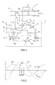
Figure 1 illustrates a block diagram of a device for eliminating a DC current component circulating in a monophasic electrical grid, according to the present invention; -
Figure 2 illustrates the waveforms of some electrical values related to part of the device shown inFigure 1 ; -
Figure 3 illustrates a detailed view of a further part of the device shown inFigure 1 ; -
Figure 4 illustrates a detailed view of the connections of some parts of the device shown inFigure 1 . - In
Figure 1 , thenumeral 1 indicates a monophasic electrical grid for distributing alternating current electrical energy, where VGRID is the grid alternating voltage and RGRID and LGRID are the parasitic resistance and inductance distributed along the electrical grid, thenumeral 2 indicates a group of electrical power sources and/or electrical loads connected to theelectrical grid 1 and thenumeral 4 indicates a device for eliminating a DC current component circulating in theelectrical grid 1, thedevice 4 being obtained according to the present invention. The set of sources andloads 2 is connected to theelectrical grid 1 at acommon coupling point 3, that is, at the interface point between the electrical sources and the electrical loads. The set of sources andloads 2 comprises sources of electrical energy based on renewable energy sources. Thus, these electrical sources tipically comprise a DC-AC power converter connected to the electrical grid at the common coupling point. In use, these electrical sources insert into the electrical grid 1 a DC current component which circulates in theelectrical grid 1, thereby causing a continuous component voltage drop at thecommon coupling point 3 due to the presence of the parasitic resistance RGRID. - The
device 4 comprises a reactor 5 which is to be connected in parallel to theelectrical grid 1 at thecommon coupling point 3 and is designed to operate, when it is connected to theelectrical grid 1, at the "knee" (i.e. at the change of slope) of its magnetic characteristic curve in such a way as to obtain a significant and asymmetrical magnetic saturation of the reactor 5 when the DC current component is circulating in thegrid 1. In particular, the reactor 5 comprises a toroidal magnetic core and a single winding wound around the magnetic core and connected with its own terminals to theelectrical grid 1 at thecommon coupling point 3. The reactor 5 is configured as a low-power toroidal transformer having one primary winding only so that during operation of the reactor 5 the magnetic core works close to the knee of its magnetic characteristic curve and is therefore magnetically saturated when a DC current component is circulating in theelectrical grid 1. Thedevice 4 comprises acurrent sensor 6 for measuring the reactor current IR which circulates in the winding of the reactor 5. Thecurrent sensor 6 can consist of, for example, a current or amperometric transformer coupled to a point of the winding of the reactor 5. The current transformer ensures adequate galvanic isolation during measurement and provides a measurement which does not have any intrinsic offset problems. Given that the reactor 5 has a single winding only, the measured reactor current IR coincides with the magnetizing current of the reactor 5, whose waveform is strongly linked to the value of the voltage DC component at thecommon coupling point 3. - In
Figure 2 , VGRID indicates the waveform of the grid voltage (alternating component) present between theterminals positive bump 100 and anegative bump 101 respectively at the half-cycle and full cycle of the grid voltage VGRID. The example inFigure 2 refers to a positive DC voltage component which generates a magnetizing current IM with apositive bump 100 which is greater than thenegative bump 101. As the amplitude of the DC current component increases so does the difference in extension between thepositive bump 100 and thenegative bump 101. The DC component therefore generates a DC voltage component which in turn generates a distortion in the waveform of the magnetizing current IM which is then detectable by thecurrent sensor 6. - With reference to
Figure 1 , thedevice 4 comprises apower converter 7, alow pass filter 8 for coupling theoutput 9 of thepower converter 8 to theelectrical grid 1 at thecommon coupling point 3 and a furthercurrent sensor 10 to measure the converter current IJ which circulates between theoutput 9 of thepower converter 7 and theelectrical grid 1. Thelow pass filter 8 is dimensioned to have a reduced oscillation ("ripple") on the current which thepower converter 7 injects into theelectrical grid 1. - The
power converter 7 consists, for example, of a transistor full-bridge of the known type whose structure is shown inFigure 3 . With reference toFigure 3 , the output of theconverter 7 is indicated by thenumeral 9, the power supply input of theconverter 6 is indicated by thenumeral 11 and the control inputs of theconverter 7 are indicated by 12a, 12b, 12c and 12d respectively. Thelow pass filter 8 is a common LC filter. Thecurrent sensor 10 is a current or amperometric transformer and is connected between theoutput 9 of thepower converter 7 and the input of thelow pass filter 8. - In an alternative embodiment of the invention (not illustrated), the
current sensor 10 is connected between the output of thelow pass filter 8 and thecommon coupling point 3. - With reference to
Figure 1 , thedevice 4 comprises a phase-lockedloop 13 which is connected to thecommon coupling point 3 in order to receive the grid voltage VGRID and to supply instants of zero-crossing of the grid voltage VGRID. Thedevice 4 also comprises aDC component detector 14 which is configured to calculate, during each cycle T of the grid voltage, a positive saturation index SIP and a negative saturation index SIN by integrating the measured current IR in the neighbourhood of the zero-crossing instants respectively of the half-period and of the period of the grid voltage VGRID. Thedevice 4 is also configured to calculate a voltage indicator VIND as the difference between the two saturation indexes SIP and SIN. The voltage indicator VIND is an indicator of the DC voltage component at thecommon coupling point 3. In particular, the saturation indexes SIP and SIN are calculated in accordance with the following formulae:
- In these formulae, T is the cycle of the grid voltage VGRID and ΔT is half of the neighbourhood centred on the zero-crossing instants. The voltage indicator VIND is therefore calculated as follows:

- The
device 4 comprises a current regulator constituted by a regulator of the proportional-integral type (regulator PI) 15 which receives the voltage indicator VIND and provides a corresponding IDC estimate of the DC current component circulating in theelectrical grid 1. The IDC estimated current, with the sign changed, corresponds to the current that thepower converter 7 must inject in or absorb from the electrical grid in order to compensate for or eliminate the DC current component that circulates in theelectrical grid 1. - Thus, the DC current component which circulates in the
electrical grid 1 is measured indirectly, that is, by measurement of the DC component of the voltage at thecommon coupling point 3, which in turn is measured indirectly by measuring the reactor current. In this way it is possible to detect voltage DC current components of some tens of mV superimposed on a grid voltage VGRID having a peak-to-peak amplitude in the order of 600 V. Furthermore, the measurement strategy described above is very precise and does not have any problems of offset in the measuring chain of the current circulating in the reactor 5. - The
device 4 comprises analgebraic adder 16 for calculating a converter current reference ("set point") IJSET as the sum of multiple contributions, the first of which is the estimated current IDC with an inverted sign. Thedevice 4 also comprises acurrent controller 17 which receives the measured converter current IJ and the converter current set point IJSET and controls thepower converter 7 in such a way that the measured converter current IJ becomes substantially equal to the current set point IJSET. - The
device 4 comprises at least onecapacitor 18 connected to thesupply input 11 of thepower converter 7, avoltage measurer 19 for measuring the supply voltage VH at the terminals of thecapacitor 18, and asubtractor 20 for measuring a voltage error ΔVH as the difference between the measured supply voltage VH and a supply voltage set point VHSET. Thevoltage measurer 19 is constituted, for example, of a resistive divider or a linear optoisolator. Thedevice 4 also comprises a further current regulator constituted by a proportional-integral regulator (regulator PI) 21, which receives the voltage error ΔVH and provides a corresponding supply current set point IHSET for thepower converter 7. Thedevice 4 also comprises amultiplier 22 whose function is to multiply the supply current set point IHSET by sin(θGRID), where θGRID is the phase angle of the grid voltage VGRID at thecommon coupling point 3, in order to obtain an active supply current set point IHASET. The phase angle θGRID is supplied by the phase-lockedloop 13. - The active supply current set point IHASET represents the amount of active current that the
power converter 7 must absorb from theelectrical grid 1 to obtain an independent power supply and to compensate for its own electrical power losses. In other words, the purpose of thePI regulator 21 is to maintain at a constant level the supply voltage VH at thecapacitor 18 terminals by absorbing from the electrical grid 1 a sinusoidal current component with a unitary power factor. - The active supply current set point IHASET is a second contribution input to the
algebraic adder 16. Thus, the injected current set point IJSET is calculated as the algebraic sum of a first current component (-IDC) to be injected into, or absorbed by the electrical grid in order to compensate (or eliminate) the DC current component circulating in theelectrical grid 1 and a second current component (+IHASET) to be absorbed from theelectrical grid 1 for the independent supply of thedevice 4. - With reference to
Figure 4 , thecurrent controller 17 comprises, for example, asubtractor 23 for determining a current error ΔIJ as the difference between the measured converter current IJ and the converter current set point IJSET, a proportional-integral regulator 24 which receives the current signal ΔIJ, an adder 25 connected to the output of thePI regulator 24 used to introduce an open-loop (VFF) contribution and aPWM generator 26, that is, a three-level single-pole generator connected between the output of the adder 25 and thecontrol inputs 12a to 12d of thepower converter 7. - The blocks indicated by 13 to 17 and 20 to 22 in
Figure 1 perform the processing function of the measured reactor current IR and the measured supply voltage VH in order to determine a converter current set point IJSET and are preferably implemented by a DSP (Digital Signal Processor) configured using a related software. As an alternative, theblocks 13 to 17 and 20 to 22 can be implemented using dedicated hardware. In particular, theblocks - In a further embodiment of the invention not shown here, the voltage indicator VID is calculated as:

and therefore thealgebraic adder 16 sums the supply active current IHASET with the estimated current IDC without inverting the sign of the estimated current IDC. - The main advantage of the
device 4 described above is that it is connectable to any point of theelectrical grid 1, and in particular to acommon coupling point 3 of any type of electrical load or AC-DC or DC-AC electronic converters, in order to compensate for, or eliminate in a precise way a DC current component circulating in theelectrical grid 1. Furthermore, thedevice 4 is of the stand-alone type, that is, it does not need an external power supply source outside theelectrical grid 1 because it is able to power itself independently by absorbing the necessary quantity of active electrical power.
Claims (10)
- Device for eliminating a DC current component circulating in an electrical grid; the device (4) being characterised in that it comprises an reactor (5), which has to be connected in parallel to the electrical grid (1) at a given point (3) of the latter and is designed to operate, when it is connected to the electrical grid (1), in correspondence to the knee of its magnetic characteristic, so as to obtain a magnetic saturation of said reactor (5) in presence of said DC current component, a first current sensor (6) for measuring the reactor current (IR), a power converter (7), a low-pass filter (8) for coupling the output (9) of the power converter (7) to the electrical grid (1) at said given point (3), a second current sensor (10) for measuring a converter current (IJ) circulating between the output (9) of the power converter (7) and said given point (3) of the electrical grid (1), first processing means (13-16, 20-22) for determining, as a function of at least the measured reactor current (IR), a converter current set point (IJSET), and a current controller (17) for controlling the power converter (7) in such a way that the measured converter current (IJ) becomes substantially equal to said converter current set point (IJSET).
- Device according to claim 1, wherein said first processing means (13-16, 20-22) comprise second processing means (13, 14) for determining, as a function of said measured reactor current (IR), an indicator (VIND) of the DC voltage component at said given point (3) of the electrical grid (1), and current regulating means (15, 16, 21, 22) configured to regulate said converter current set point (IJSET) as a function of said DC voltage component indicator (VIND).
- Device according to claim 2, wherein said current regulating means (15, 16, 21, 22) comprise a first regulator of the proportional-integral type (15), which receives said DC voltage component indicator (VIND) and provides a corresponding estimate (IDC) of said DC current component, and third processing means (16) for determining said converter current set point (IJSET) as a function of said DC current component estimate (IDC).
- Device according to claim 2 or 3, wherein said second processing means (13, 14) comprise a phase-locked loop (13), which is connected to said given point (3) of the electrical grid (1) in order to receive the grid voltage (VGRID) and to provide instants of zero-crossing of the grid voltage (IGRID), and DC component detecting means (14), which are configured to calculate, during each cycle of the grid voltage (VGRID), a positive saturation index (SIP) and a negative saturation index (SIN) by integrating said measured reactor current (IR) in a neighbourhood of the zero-crossing instants of the half-period and, respectively, of the period of the grid voltage (VGRID) and to calculate said DC voltage component indicator (VIND) as a difference between the two saturation indexes (SIP, SIN).
- Device according to any of the claims from 2 to 4, and comprising capacitor means (18) connected to the supply input (11) of said power converter (7) and voltage measuring means (19) for measuring a supply voltage (VH) at the ends of said capacitor means (18); said first processing means (13-16, 20-22) comprising fourth processing means (20) for determining a voltage error (ΔVH) as a function of the measured supply voltage (VH) and of a supply voltage set point (VHSET); said current regulating means (15, 16, 21, 22) being configured to determine said converter current set point (IJSET) as a function of said voltage error (ΔVH).
- Device according to claim 5, wherein said current regulating means (15, 16, 21, 22) comprise a second regulator of the proportional-integral type (21), which receives said voltage error signal (ΔVH) and provides a corresponding supply current set point (IHSET) for said power converter (7), and fifth processing means (16, 22) for determining said converter current set point (IJSET) as a function of said supply current set point (IHSET).
- Device according to claims 3 and 6, wherein said second processing means (13, 14) comprise a phase-locked loop (13), which is connected to said given point (3) of the electrical grid (1) in order to receive the grid voltage (VGRID) and to provide phase angle (θGRID) of the grid voltage (VGRID) in said given Point (3); said fifth processing means (16, 22) comprising sixth processing means (22), which are suited to determine an active supply current set point (IHASET) as a function of said supply current set point (IHSET) and of said phase angle (θGRID), and said third processing means, which consist of an algebraic adder (16) for calculating said converter current set point (IJSET) as an algebraic addition of contributions, a first contribution being function of said DC current component estimate (IDC) and a second contribution being said active supply current set point (IHASET).
- Device according to any of the previous claims, wherein said second current sensor (10) is arranged between the output (9) of said power converter (7) and said low-pass filter (8).
- Device according to any of the previous claims, wherein said current controller (17) comprises seventh processing means (23) for determining a current error (ΔIH) as a function of said measured reactor current (IR) and of said converter current set point (IJSET), a third regulator of the proportional-integral type (24) connected to said seventh processing means (23) for receiving said current error (ΔIH), and a PWM generator (26) connected between said third proportional-integral regulator (24) and control inputs (12a-12d) of said power converter (7).
- Use of a device for eliminating a DC current component circulating in an electrical grid, characterised in that the device (4) is of the type claimed in any of the previous claims and in that said reactor (5) is connected in parallel to the electrical grid (3) at a common coupling point (3) of a set of electrical sources and/or electrical loads (2).
Applications Claiming Priority (1)
| Application Number | Priority Date | Filing Date | Title |
|---|---|---|---|
| ITBO2010A000666A IT1402466B1 (en) | 2010-11-05 | 2010-11-05 | DEVICE TO ELIMINATE A CONTINUOUS CIRCULATING CURRENT IN A SINGLE-PHASE ELECTRIC NETWORK |
Publications (1)
| Publication Number | Publication Date |
|---|---|
| EP2451040A1 true EP2451040A1 (en) | 2012-05-09 |
Family
ID=43742526
Family Applications (1)
| Application Number | Title | Priority Date | Filing Date |
|---|---|---|---|
| EP11186072A Withdrawn EP2451040A1 (en) | 2010-11-05 | 2011-10-21 | Device for eliminating a dc current component circulating in a monophasic electrical grid |
Country Status (2)
| Country | Link |
|---|---|
| EP (1) | EP2451040A1 (en) |
| IT (1) | IT1402466B1 (en) |
Cited By (3)
| Publication number | Priority date | Publication date | Assignee | Title |
|---|---|---|---|---|
| CN103715699A (en) * | 2013-12-02 | 2014-04-09 | 国家电网公司 | Low-voltage distribution network line reactive compensation device and compensation method |
| CN109326428A (en) * | 2018-10-29 | 2019-02-12 | 李晓明 | A kind of magnet controlled reactor and method |
| CN110739858A (en) * | 2019-10-31 | 2020-01-31 | 太原理工大学 | A Bidirectional DC/DC Device Using Auxiliary Winding to Adjust Power Inductance |
Citations (5)
| Publication number | Priority date | Publication date | Assignee | Title |
|---|---|---|---|---|
| US4434376A (en) * | 1979-07-23 | 1984-02-28 | Electric Power Research Institute, Inc. | Method and means for damping subsynchronous oscillations and DC offset in an AC power system |
| US4647837A (en) * | 1983-10-12 | 1987-03-03 | Bbc Brown, Boveri & Company, Limited | Reactive-power compensator for compensating a reactive-current component in an alternating-voltage system |
| EP0551683A1 (en) * | 1990-10-29 | 1993-07-21 | Electric Power Research Institute, Inc | Improved feedback control system for static volt ampere reactive compensator with thyristor controlled reactances |
| US20040090212A1 (en) * | 2002-11-08 | 2004-05-13 | Uis Abler Electronics Co., Ltd. | Hybrid reactive power compensation device |
| JP2008054366A (en) * | 2006-08-22 | 2008-03-06 | Omron Corp | Isolated operation detection device |
-
2010
- 2010-11-05 IT ITBO2010A000666A patent/IT1402466B1/en active
-
2011
- 2011-10-21 EP EP11186072A patent/EP2451040A1/en not_active Withdrawn
Patent Citations (5)
| Publication number | Priority date | Publication date | Assignee | Title |
|---|---|---|---|---|
| US4434376A (en) * | 1979-07-23 | 1984-02-28 | Electric Power Research Institute, Inc. | Method and means for damping subsynchronous oscillations and DC offset in an AC power system |
| US4647837A (en) * | 1983-10-12 | 1987-03-03 | Bbc Brown, Boveri & Company, Limited | Reactive-power compensator for compensating a reactive-current component in an alternating-voltage system |
| EP0551683A1 (en) * | 1990-10-29 | 1993-07-21 | Electric Power Research Institute, Inc | Improved feedback control system for static volt ampere reactive compensator with thyristor controlled reactances |
| US20040090212A1 (en) * | 2002-11-08 | 2004-05-13 | Uis Abler Electronics Co., Ltd. | Hybrid reactive power compensation device |
| JP2008054366A (en) * | 2006-08-22 | 2008-03-06 | Omron Corp | Isolated operation detection device |
Cited By (5)
| Publication number | Priority date | Publication date | Assignee | Title |
|---|---|---|---|---|
| CN103715699A (en) * | 2013-12-02 | 2014-04-09 | 国家电网公司 | Low-voltage distribution network line reactive compensation device and compensation method |
| CN103715699B (en) * | 2013-12-02 | 2015-10-28 | 国家电网公司 | A kind of low-voltage distribution network reactive power compensation system device and compensation method |
| CN109326428A (en) * | 2018-10-29 | 2019-02-12 | 李晓明 | A kind of magnet controlled reactor and method |
| CN109326428B (en) * | 2018-10-29 | 2020-03-10 | 李晓明 | Magnetically controlled reactor and method |
| CN110739858A (en) * | 2019-10-31 | 2020-01-31 | 太原理工大学 | A Bidirectional DC/DC Device Using Auxiliary Winding to Adjust Power Inductance |
Also Published As
| Publication number | Publication date |
|---|---|
| IT1402466B1 (en) | 2013-09-13 |
| ITBO20100666A1 (en) | 2012-05-06 |
Similar Documents
| Publication | Publication Date | Title |
|---|---|---|
| US7834480B2 (en) | Energy converter system with reactive-power-management | |
| Huynh et al. | Direct AC–AC active-clamped half-bridge converter for inductive charging applications | |
| CN104330627B (en) | Automatic power grid resonance detection method based on active injection current | |
| Yan et al. | Minimization of the DC component in transformerless three-phase grid-connected photovoltaic inverters | |
| Lidozzi et al. | Sinusoidal voltage shaping of inverter-equipped stand-alone generating units | |
| EP2451040A1 (en) | Device for eliminating a dc current component circulating in a monophasic electrical grid | |
| Jia et al. | An I/Q phase detection-based harmonic-insensitive phase synchronization method for bidirectional wireless power transfer system | |
| Patel et al. | EV charging station with cascaded low-pass filtering scheme-based control of unified power quality conditioner | |
| JP2015223056A (en) | Exciting current detection circuit, exciting current detection method, control circuit of inverter circuit, and power supply device | |
| Chinmay et al. | Optimum design of dynamic voltage restorer for voltage sag mitigation in distribution network | |
| Marin-Hurtado et al. | Calculation of core losses in magnetic materials under nonsinusoidal excitation | |
| US8964425B2 (en) | Power converter with controlled current source to reduce harmonic distortion | |
| Ito et al. | Harmonic current reduction control for grid-connected PV generation systems | |
| WO2019182161A1 (en) | Power converting system, power converting device, power converting method, power generating system, effective power transferring system, power grid, power transferring system, load system, and power transmission and distribution system | |
| US20150222198A1 (en) | Method and System for Transmitting Voltage and Current Between a Source and a Load | |
| JPH07298627A (en) | Power converter controller | |
| RU2522706C1 (en) | Bridge calibration device for induction-type electric meters of active energy | |
| Kavimandan et al. | A control scheme to mitigate the dead-time effects in a wireless power transfer system | |
| JP2024544574A (en) | Apparatus, system and method for measuring high voltage on a high voltage node - Patents.com | |
| CN203416173U (en) | Power supply apparatus controlling power semiconductor devices valve group | |
| CN103326592A (en) | Power device for controlling valve group of power semiconductor device | |
| US12609608B2 (en) | Mains reconstruction unit | |
| Ikeda et al. | Constant dc-capacitor voltage-control-based strategy of a smart charger for electric vehicles in actual single-phase three-wire distribution feeders | |
| Barater et al. | Active filter for dc current components in three-phase distribution grids | |
| Karunadasa et al. | Load Injected DC Current in Distribution Transformers: Investigation and Elimination |
Legal Events
| Date | Code | Title | Description |
|---|---|---|---|
| PUAI | Public reference made under article 153(3) epc to a published international application that has entered the european phase |
Free format text: ORIGINAL CODE: 0009012 |
|
| AK | Designated contracting states |
Kind code of ref document: A1 Designated state(s): AL AT BE BG CH CY CZ DE DK EE ES FI FR GB GR HR HU IE IS IT LI LT LU LV MC MK MT NL NO PL PT RO RS SE SI SK SM TR |
|
| AX | Request for extension of the european patent |
Extension state: BA ME |
|
| 17P | Request for examination filed |
Effective date: 20120403 |
|
| STAA | Information on the status of an ep patent application or granted ep patent |
Free format text: STATUS: THE APPLICATION IS DEEMED TO BE WITHDRAWN |
|
| 18D | Application deemed to be withdrawn |
Effective date: 20160503 |