EP2450596B1 - Mécanisme d'engrenages planétaires - Google Patents
Mécanisme d'engrenages planétaires Download PDFInfo
- Publication number
- EP2450596B1 EP2450596B1 EP10793972.0A EP10793972A EP2450596B1 EP 2450596 B1 EP2450596 B1 EP 2450596B1 EP 10793972 A EP10793972 A EP 10793972A EP 2450596 B1 EP2450596 B1 EP 2450596B1
- Authority
- EP
- European Patent Office
- Prior art keywords
- toothed gear
- planetary gear
- externally toothed
- pins
- internally toothed
- Prior art date
- Legal status (The legal status is an assumption and is not a legal conclusion. Google has not performed a legal analysis and makes no representation as to the accuracy of the status listed.)
- Not-in-force
Links
- 230000007246 mechanism Effects 0.000 title claims description 84
- 230000010355 oscillation Effects 0.000 claims 1
- 239000003638 chemical reducing agent Substances 0.000 description 51
- 230000033001 locomotion Effects 0.000 description 10
- 238000003754 machining Methods 0.000 description 7
- 238000010276 construction Methods 0.000 description 6
- 230000013011 mating Effects 0.000 description 6
- 238000004519 manufacturing process Methods 0.000 description 5
- 230000015572 biosynthetic process Effects 0.000 description 4
- 230000000694 effects Effects 0.000 description 4
- 238000006243 chemical reaction Methods 0.000 description 3
- 230000002093 peripheral effect Effects 0.000 description 3
- 239000011295 pitch Substances 0.000 description 3
- 230000004323 axial length Effects 0.000 description 1
- 230000005540 biological transmission Effects 0.000 description 1
- 230000001419 dependent effect Effects 0.000 description 1
- 238000011161 development Methods 0.000 description 1
- 230000018109 developmental process Effects 0.000 description 1
- 238000006073 displacement reaction Methods 0.000 description 1
- 238000009434 installation Methods 0.000 description 1
- 238000011144 upstream manufacturing Methods 0.000 description 1
Images


Classifications
-
- F—MECHANICAL ENGINEERING; LIGHTING; HEATING; WEAPONS; BLASTING
- F16—ENGINEERING ELEMENTS AND UNITS; GENERAL MEASURES FOR PRODUCING AND MAINTAINING EFFECTIVE FUNCTIONING OF MACHINES OR INSTALLATIONS; THERMAL INSULATION IN GENERAL
- F16H—GEARING
- F16H1/00—Toothed gearings for conveying rotary motion
- F16H1/28—Toothed gearings for conveying rotary motion with gears having orbital motion
- F16H1/32—Toothed gearings for conveying rotary motion with gears having orbital motion in which the central axis of the gearing lies inside the periphery of an orbital gear
Definitions
- the present invention relates to a planetary gear mechanism according to the preamble of claim 1.
- a speed reducer having a planetary gear mechanism is used for reducing the speed of rotation of a motor, for example.
- a planetary gear mechanism having a first shaft, an externally toothed gear mounted via an eccentric body provided on the first shaft such that the gear is eccentrically rotatable relative to the first shaft, an internally toothed gear which the externally toothed gear internally contacts and meshes with, and a second shaft coupled to the externally toothed gear via a means for transmitting only the rotational component of the externally toothed gear.
- a cycloid differential planetary gear mechanism is known.
- the speed reducer using the cycloid differential planetary gear mechanism achieves a large speed reduction ratio with one reduction stage, and operates with a high efficiency owing to a high contact ratio, as compared with an planetary gear mechanism having general gears of an involute tooth profile.
- the speed reducer of the cycloid type has a complicated mechanism for taking output out of eccentric oscillating rotation, and is likely to be available at a high cost.
- a general cycloid differential planetary gear mechanism causes an epitrochoid externally toothed gear to internally contact a pin gear as an internal gear and eccentrically oscillate, so as to provide output via inner pins.
- an externally toothed gear having the same structure as and opposite in phase to the above-indicated externally toothed gear is added, or two pieces of externally toothed gears having the same structure and shifted in phase by 120° from each other in terms of the direction of displacement of the center are added (see Patent Document 1).
- the known cycloid differential planetary gear mechanism has a problem that it cannot provide a large speed change ratio (reduction ratio). Therefore, in order to achieve an even larger reduction ratio (e.g., 100 or larger) with the speed reducer having the known mechanism, another stage of speed reduction mechanism or speed reduction unit must be added the upstream side of the input shaft or the downstream side of the output shaft, resulting in a significant increase in the cost and an increase in the installation space.
- the internal gear needs to be constituted by a large number of pins, so as to provide the epitrochoid gear.
- the number of pins that can be placed on the inner periphery needs to be large.
- the diameter of each pin needs to be reduced so as to increase the number of pins. It is practically impossible or quite difficult to make this choice, eventually making it impossible to realize a structure that provides a large reduction ratio.
- Patent Document 1 JP 2002 0266955 A
- JP 49 093765 discloses a planetary gear mechanism according to the preamble of claim 1.
- the present invention has been developed in view of the above-described actual situations, and an object of the invention is to provide a planetary gear mechanism that can achieve a large speed change ratio and also achieve reduction in size.
- the oscillating member eccentrically oscillates via the eccentric portion provided on the third member, and undergoes rotary motion about the eccentric axis.
- the oscillating member is formed with the first externally toothed gear that engages with (externally contacts and meshes with) the first internally toothed gear formed on the first member, and the rotational speed of the rotary motion about the axis of the input and output shafts (the central axis of the third member) is changed to the speed corresponding to the speed change ratio determined by the number of teeth of the first externally toothed gear and that of the first internally toothed gear.
- the oscillating member is also formed with the second externally toothed gear that engages with (externally contacts and meshes with) the second internally toothed gear provided on the second member as the other of the input and output shafts.
- the oscillating member eccentrically oscillates and rotates at the speed to which the rotational speed has been changed by the first gear set (the first externally toothed gear and the first internally toothed gear), and the rotational speed of the eccentric oscillating rotation is changed to the speed corresponding to the speed change ratio determined by the number of teeth of the second externally toothed gear and that of the second internally toothed gear.
- the second externally toothed gear is formed on the oscillating member, and the rotation whose speed has been changed by the second gear set (the second externally toothed gear and the second internally toothed gear) is delivered to the second member via the second internally toothed gear.
- the rotational speed at which the third member rotates is changed by both of the first gear set and the second gear set, and the resulting rotation is delivered from the second member.
- the oscillating member rotates in the direction opposite to that of the third member, and the second member rotates in the direction opposite to that of the oscillating member.
- the planetary gear mechanism of the invention may change the speed of rotation of the second member and deliver it to the third member.
- the rotation is transmitted via the second member, the second internally toothed gear, the second externally toothed gear, the first internally toothed gear, the first externally toothed gear, the oscillating member, and the third member, in the order of description, so that the speed of the rotation is changed.
- the planetary gear mechanism of the invention is constructed such that the rotational speed that has been changed by one of the first and second gear sets is further changed by the other gear set.
- a large speed change ratio can be obtained by adjusting the speed ratios or gear ratios of the first gear set and the second gear set.
- the speed ratio (reduction ratio) of each of the gear sets can be determined by adjusting the numbers of teeth of the externally toothed gear and internally toothed gear that constitute each of the gear sets.
- the planetary gear mechanism of the invention is constructed such that the two gear sets that change the speed are formed as a unit, to thus provide a speed reducer that is small in size but provides high torque and a large reduction ratio, which advantageously contributes to reduction in the size of the system.
- the first and second externally toothed gears are formed integrally on the oscillating member, so that the axial length of the oscillating member can be advantageously shortened, and the overall size of the planetary gear mechanism can be advantageously reduced.
- the planetary gear mechanism of the invention In the planetary gear mechanism of the invention, high machining or working accuracy is required in formation of only the engaging faces of the first and second externally toothed gears provided on the oscillating member and the internally toothed gears engaging with the respective externally toothed gears (the meshing faces of the gears). In other words, high machining or working accuracy is not required in formation of the other portions. Thus, the planetary gear mechanism of the invention exerts a cost reduction effect.
- the inner pin holes through which the inner pins extend need to be formed in the externally toothed gear, and there is a limitation to reduction of the outside diameter of the externally toothed gear itself.
- the planetary gear mechanism of the invention in which two externally toothed gears are provided on the oscillating face plate (that functions equally with the externally toothed gear), does not use any component that requires large space, like the inner pin holes. Consequently, the outside diameter can be advantageously reduced.
- each of the pins mentioned in claims 2 and 3 extends in the direction of the axis of the input and output shafts, so as to be able to mesh with the mating gear. More preferably, each pin extends in a direction perpendicular to the oscillating face.
- the other gear of one gear set is formed with the trochoid tooth profile, so that the area of meshing between the externally toothed gear and internally toothed gear that constitute the gear set can be increased.
- the trochoid tooth profile of the externally toothed gear is preferably an epitrochoid tooth profile, and that of the internally toothed gear is preferably a hypotrochoid tooth profile.
- the two externally toothed gears of the two gear sets are provided on the same axis; therefore, the oscillating member that eccentrically oscillates and rotates can be shared by the two gear sets, and the number of components is prevented from being increased.
- each of the first pins and second pins consists of a pin body and a collar.
- the meshing face of the pin with the mating gear is formed by the surface of the collar.
- the collar is arranged to be rotatable relative to the pin body; therefore, when the pins and the mating gear mesh with each other, slipping of the meshing faces can be absorbed by the rotating collars, thus assuring highly efficient meshing.
- a backlash in meshing can be easily adjusted by adjusting the outside diameter of the collar.
- the first support bearing is disposed between the eccentric portion and the oscillating member, so that eccentric rotation of the eccentric portion can be converted into oscillating rotation of the oscillating member. Also, the eccentric portion can receive radial stress applied to the oscillating member.
- the axial positions of the third member and the second member coincide with each other, and the second support bearing is disposed between these members.
- the second support bearing is disposed between the eccentric portion of the third member and the second member, so that the stress applied radially inwards to the eccentric portion can be received by the second member.
- the planetary gear mechanism of the invention according to claim 10 is preferably a speed reducing mechanism that reduces the speed of the input from the third member and delivers it to the second member, since the speed can be changed with the mechanism that is available at a low cost and is small in size.
- the planetary gear mechanism of the invention is available at a low cost and can be small-sized; therefore, it is preferable to use the planetary gear mechanism as a speed reducer for reducing the speed of the output of a motor in a robot, for example.
- the first internally toothed gear is formed by the first pins that protrude from the first member, so that the first externally toothed gear that meshes with the first internally toothed gear can be formed by cutting the outer peripheral edge of the oscillating member.
- the first externally toothed gear can be easily formed by cutting through the oscillating member.
- the second externally toothed gear is formed by the second pins that protrude from the oscillating member; therefore, even when the second externally toothed gear has a smaller diameter than the first externally toothed gear, the oscillating member need not be formed by machining with a pocket or a hollow portion, unlike the case where the gear is formed by cutting, thus assuring easy production thereof.
- the first externally toothed gear is formed by the first pins that protrude from the oscillating member; so that the first internally toothed gear that meshes with the first externally toothed gear can be formed by cutting on the first member.
- the first internally toothed gear can be formed by cutting through a wall of the first member as the housing, thus assuring easy production thereof.
- the second internally toothed gear is formed by the second pins that protrude from the second member.
- the second member need not be formed by machining with a pocket or a hollow portion, thus assuring each production thereof.
- the third member has a counter balancer that cancels out unbalanced rotation of the eccentric portion.
- the unbalanced rotation caused by the eccentric portion can be cancelled out, and vibration of the planetary gear mechanism can be suppressed.
- the construction of the counter balancer is not particularly limited provided that the shape and position of the counter balancer are determined so that it can cancel out the unbalanced rotation of the eccentric portion.
- the counter balancer is in the form of a weight reducing hole formed by partially hollowing the third member.
- the inner ring of the third support bearing is formed integrally with the second member, so that the number of components can be reduced, and the planetary gear mechanism is available at a reduced cost.
- the case of the electric motor is formed integrally with the first member or the second member, and the output shaft of the electric motor is formed integrally with the third member, so that the number of components can be reduced, and the planetary gear mechanism is available at a reduced cost.
- FIG. 1 shows a speed reducer in which an planetary gear mechanism of this embodiment is employed.
- driving force applied from a motor M to an input shaft 2 is delivered to an output shaft 7 while its speed is reduced.
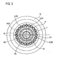
- FIG. 2 shows an A-A section in FIG. 1 , and a B-B section in FIG. 1 is shown in FIG. 3 , respectively.
- the speed reducer 1 of this embodiment has the motor M, a housing H, the input shaft 2, an oscillating face plate 3, first pins 4, second pins 5, an internally toothed gear 6, and the output shaft 7.
- the motor M (corresponding to the electric motor of this invention) is a member that produces a rotation output.
- the motor M is not particularly limited.
- the housing H (corresponding to the first member of the invention) is a member that is fixed to the motor M, and forms a part of the outer peripheral shape of the speed reducer 1. Also, the housing H rotatably houses and supports members, such as a rotary shaft MJ of the motor M, the input shaft 2 (corresponding to the third member and first shaft of the invention), the oscillating face plate 3 (corresponding to the oscillating member of the invention), the first pins 4, the second pins 5, the internally toothed gear 6, and the output shaft 7 (corresponding to the second member and second shaft of the invention when it includes the internally toothed gear 6).
- members such as a rotary shaft MJ of the motor M, the input shaft 2 (corresponding to the third member and first shaft of the invention), the oscillating face plate 3 (corresponding to the oscillating member of the invention), the first pins 4, the second pins 5, the internally toothed gear 6, and the output shaft 7 (corresponding to the second member and second shaft of the invention when it includes the internally toothed gear 6).
- the housing H rotatably supports the input shaft 2 and the output shaft 7 such that the axes of these shafts coincide with each other and provide a common axis (which is the axis of input and output shafts and is denoted by ⁇ in the figures).
- the input shaft 2 is a generally cylindrical member fixed to the rotary shaft MJ of the motor M.
- the input shaft 2 has a reduced-diameter portion 20 that is fitted on and fixed to the rotary shaft MJ of the motor M, and a cylindrical increased-diameter portion 21 that is located on the side of the distal side of the reduced-diameter portion 20 and has larger inside diameter and larger outside diameter than those of the reduced-diameter portion 20.
- the reduced-diameter portion 20 and the increased-diameter portion 21 are formed such that their inner and outer diameters change gradually (in steps), as shown in FIG. 1 .
- the reduced-diameter portion 20 is placed in a rotatable condition, with an input shaft supporting bearing 80 interposed between the reduced-diameter portion 20 and the housing H.
- the increased-diameter portion 21 includes an eccentric portion 22 having a radially outer circumferential surface that has an eccentric shape with its center displaced from the center of the input shaft 2. Namely, as the input shaft 2 rotates about the axis of the input and output shafts, the eccentric portion 22 also rotates about the axis of the input and output shafts so that the outer circumferential surface of the eccentric portion 22 oscillates.
- the outer circumferential surface of the eccentric portion 22 is formed in the shape of a true circle whose center lies on an eccentric axis (denoted by e ⁇ in the figures) located at a different position from the axis of the input and output shafts.
- the input shaft 2 is provided with a counter balancer 23 located closer to the motor M than a portion of the reduced-diameter portion 20 which is supported by the housing H.
- the counter balancer 23 is positioned so as to cancel out unbalanced rotation produced by the eccentric portion 22. More specifically, the counter balancer 23 is mounted such that its phase is opposite to that of the eccentric shape of the eccentric portion 22, as shown in FIG. 4.
- FIG. 4 is a schematic view as seen from the output shaft 7 side toward the motor M, which makes a phase difference between the oscillating face plate 3 and the counter balancer 23 understood.
- the oscillating face plate 3 is a disc-like member in which (the eccentric portion 22 of) the increased-diameter portion 21 is inserted via a first support bearing 81.
- the oscillating face plate 3 has a cylindrical portion 30 in which (the eccentric portion 22 of) the increased-diameter portion 21 is inserted via the first support bearing 81, and a disc-shaped disc portion 31 that extends perpendicularly to the axial direction at one end portion of the cylindrical portion 30 closer to the motor M.
- the cylindrical portion 30 is supported by the eccentric portion 22 via the first support bearing 81.
- the oscillating face plate 3 is formed at its outer circumferential surface with a first externally toothed gear 32 that engages with a first internally toothed gear formed on the housing H and having a center located on the axis of the input and output shafts, and a second externally toothed gear that engages with the second internally toothed gear 6.
- the oscillating face plate 3 rotates with respect to the eccentric axis, and the eccentric axis rotates about the axis of the input and output shafts, due to the engagement of the respective internally toothed gears with the corresponding externally toothed gears.
- the externally toothed gear 32 of the epitrochoid type is formed in the circumferential direction, with a predetermined pitch (the number of teeth is 29 in this embodiment).
- the externally toothed gear 32 corresponds to the first externally toothed gear of the invention.
- a plurality of second pins 5 are fixed at equal intervals to the disc portion 31 of the oscillating face plate 3.
- the second pins 5 are fixed to one surface of the disc portion 31 of the oscillating face plate 3 so as to protrude in a direction (direction of the axis of the input and output shafts) away from the motor M.
- the pins 5 form an externally toothed gear corresponding to the second externally toothed gear of the invention.
- Each of the second pins 5 consists of a columnar pin body 50 fixed to the oscillating face plate 3, and a cylindrical collar 51 rotatably fitted on the pin body 50, as shown in FIG. 1 .
- the internally toothed gear corresponds to the first internally toothed gear of the invention.
- the internally toothed gear is formed at the inner circumferential surface of the housing H by the first pins 4 fixed to the housing H.
- the first pins 4 are fixed in a condition where they extend in parallel with the axial direction of the input shaft 2 and the output shaft 7 (the direction of the axis of the input and output shafts).
- a plurality of pins in this embodiment, 30 pins that is larger by one than the number of the meshing external teeth) as the first pins 4 are fixed at equal intervals (equal pitches).
- the first pins 4 engage (mesh) with the externally toothed gear 32 formed on the end portion of the disc portion 31.
- the externally toothed gear 32 (the first externally toothed gear) and the second externally toothed gear consisting of the second pins 5 are both formed about the eccentric axis, coaxially with each other.
- Each of the first pins 4 consists of a columnar pin body 40 fixed to the housing H, and a cylindrical collar 41 rotatably fitted on the pin body 40, as shown in FIG. 1 .
- the internally toothed gear 6 is formed radially outwardly of the second pins 5 fixed to the disc portion 31 of the oscillating face plate 3 (in a direction away from the center of the disc portion 31), such that only a circumferential portion of the internally toothed gear 6 internally contacts and meshes with the externally toothed gear formed by the second pins 5.
- the internally toothed gear 6 having teeth on its inner circumferential surface corresponds to the second internally toothed gear of the invention.
- the internally toothed gear 6 is fixed to the output shaft 7.
- internal teeth of the hypotrochoid type are formed at a predetermined pitch (in this embodiment, the number of the teeth is 24, which is larger by one than the number of the meshing external teeth).
- the output shaft 7 consists of a disc-shaped portion 70 shaped like a disc, and an insert portion 71 that protrudes from the disc-shaped portion 70 toward the motor M and is inserted into the center of the increased-diameter portion 21 of the input shaft 2.
- the output shaft 7 is supported by the housing H via an output shaft supporting bearing 83, such that the output shaft 7 is rotatable about the axis of the input and output shafts.
- the insert portion 71 of the output shaft 7 is inserted into the center of the increased-diameter portion 21 of the input shaft 2, the insert portion 71 is mounted with a second support bearing 82 interposed between the insert portion 71 and the inner circumferential surface of the increased-diameter portion 21.
- the motor M is operated.
- the input shaft 2 rotates via the rotary shaft MJ of the motor M.
- the eccentric portion 22 that constitutes the input shaft 22 rotates, so that its outer circumferential surface oscillates (eccentric rotation). Since the input shaft 2 is provided with the counter balancer 23, an imbalance in rotation which is caused by the eccentric rotation of the eccentric portion 22 is cancelled out or eliminated.
- the eccentric rotation of the eccentric portion 22 causes the oscillating face plate 3 to eccentrically oscillate via the first support bearing 81, and make rotary motion (eccentrically oscillating motion) about the eccentric axis.
- the oscillating face plate 3 has external teeth of the epitrochoid type formed on the outer periphery of the disc portion 31, and only a circumferential portion of the externally toothed gear meshes with the first pins 4 at this time.
- the oscillating face plate 3 oscillates relative to the housing H, and a circumferential position at which the external teeth and the first pins 4 fixed to the housing H mesh with each other moves, so that the oscillating face plate 3 is rotated in a direction opposite to the direction of rotation of the input shaft 2, about the eccentric axis, while its speed is reduced.
- the speed reduction ratio is determined by the numbers of teeth of the meshing gears.
- the second pins 5 are fixed to the oscillating face plate 3 that is rotated at a reduced speed, and each of the second pins 5 eccentrically oscillates and rotates along with the oscillating face plate 3.
- the second pins 5 mesh with only a circumferential portion of the internally toothed gear 6, and a circumferential position at which the second pins 5 mesh with the internally toothed gear 6 moves, so that the rotational speed is (relatively) reduced, owing to the difference in the number of teeth. This is similar to the reduction of the speed in a first gear set consisting of the above-mentioned first externally toothed gear and first internally toothed gear.
- the rotation whose speed has been reduced causes the internally toothed gear 6 to rotate in a direction opposite to the direction of rotation of the oscillating face plate 3, about the axis of the input and output shafts.
- This rotation is transmitted to the output shaft 7 to which the internally toothed gear 6 is fixed, and is taken out by the output shaft 7 as rotation resulting from further reduction of the speed of rotation of the oscillating face plate 3 and having the same direction as that of rotation of the input shaft 2.
- the speed reducer 1 of this embodiment changes the speed of rotation of the input shaft 2 using two gear sets, and the resulting rotation is delivered from the output shaft 7.
- the speed can be reduced at a large reduction ratio in each of the two gear sets, resulting in a further large reduction ratio at which rotation output can be obtained.
- the speed reducer 1 of the invention is a small-sized speed reducer that provides high torque and a large reduction ratio.
- the inner pin holes through which the inner pins extend are required to be formed in the externally toothed gear, and there is a limitation to reduction of the outside diameter of the externally toothed gear itself.
- the planetary gear mechanism of the invention in which two externally toothed gears are provided on the oscillating face plate (that functions equally with the externally toothed gear), does not use components, like the inner pin holes, which require large space. Consequently, the outside diameter can be advantageously reduced.
- the two externally toothed gears are coaxially formed on the single oscillating face plate 3, so that the gears undergo the same eccentric oscillating rotation.
- the speed reducer 1 can be simply constructed, thus providing an effect of preventing increase in the number of components.
- the input shaft 2 has the counter balancer 23 that cancels out unbalanced rotation of the eccentric portion 22, on the motor M side, so that the unbalanced rotation caused by the eccentric portion 22 is cancelled out by the counter balancer 23.
- the speed reducer 1 is less likely or unlikely to vibrate.
- the counter balancer 23 having a simple shape can be used in the planetary gear mechanism of the speed reducer 1 of this embodiment, the working cost can be advantageously reduced.
- the meshing faces of the first pins 4 and the second pins 5 which mesh with the gears, such as the mating gears 32, 6, are formed by the collars 41, 51 fitted on the pin bodies 40, 50.
- the first pins 4 and the second pins 5 mesh with the mating gears 32, 6 slipping of the tooth faces can be absorbed through rotation of the collars 41, 51, and highly efficient meshing can be achieved.
- the reaction force applied radially inwards to each of the internally toothed gears of the two gear sets, from its mating gear acts on the insert portion 71 of the output shaft 7, via the oscillating face plate 3, the first support bearing 81, the increased-diameter portion 21 of the input shaft 2, and the second support bearing 82.
- the force with which the internally toothed gear 4, 6 and the externally toothed gear 32, 5 mesh with each other in each of the gear sets is used without loss.
- the number of teeth of the first externally toothed gear (the gear 32 at the outer periphery of the disc portion 31 of the oscillating face plate 3), that of the first internally toothed gear (the gear formed by the pins 4), that of the second externally toothed gear (the gear formed by the pins 5), and that of the second internally toothed gear (the internally toothed gear 6) are indicated in TABLE 1.
- TABLE 1 First Embodiment First Modified Example Second Modified Example z1 29 29 28 z2 30 30 29 z3 24 25 26 z4 23 24 25 Reduction Ratio 116 145 242.67
- the speed reducing mechanism of the speed reducer 1 of the first embodiment is schematically illustrated in FIG. 5 .
- the reduction ratio is obtained from the numbers of teeth of the respective gears, according to the mathematical expression as indicated below.
- Reduction Ratio : n in n out z 1 ⁇ z 3 z 1 ⁇ z 3 - z 2 ⁇ z 4
- z2 is the number of teeth of the first internally toothed gear
- z1 is the number of teeth of the first externally toothed gear
- z4 is the number of teeth of the second externally toothed gear
- z3 is the number of teeth of the second internally toothed gear.
- n in is the rotational speed of the input shaft 2
- n out is the rotational speed of the output shaft 7.
- the speed reducer 1 of the first embodiment in which the numbers of teeth of the respective gears are those as indicated in TABLE 1, is able to reduce the speed of rotation of the motor M at such a large reduction ratio as 116.00.
- the speed reduction ratio can be easily adjusted by changing the number of teeth of each gear. Namely, a large reduction ratio can be advantageously achieved, even with the simple construction.
- the number of teeth of each of the gears that constitute the respective gear sets is not particularly limited, but a combination of the numbers of teeth, which provides a reduction ratio to be established by the speed reducer 1, can be selected as appropriate.
- the first externally toothed gear and the second internally toothed gear are trochoid type gears, and the first internally toothed gear and the second externally toothed gear are formed by pins.
- any of the combinations of the gears as indicated in TABLE 2 below may be selected provided that each set of meshing gears is a combination of pins and a trochoid type gear.
- the speed reducer 1 of each embodiment or example reduces the speed of rotation of the motor M using a small-sized device.
- the planetary gear mechanism of the invention is preferably used in, in particular, a small-sized robot, or the like.
- the gear mechanism of the invention is applied to the speed reducer 1 that transmits driving force of the motor M applied to the input shaft 2, to the output shaft 7, while reducing its speed.
- the gear mechanism may be applied to a speed increasing device that transmits driving force applied to the output shaft 7, to the input shaft 2, while increasing its speed.
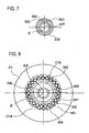
- a speed reducer 1K according to a second embodiment will be described in terms of its differences from the speed reducer 1 as described above, with reference to FIG. 6 through FIG. 9 .
- a case C1 (corresponding to the first member of the invention) of a motor M 1 (corresponding to the electric motor of the invention) is formed integrally with a housing of the speed reducer 1K.
- the case C1 also serves as the housing of the speed reducer 1K, and rotatably supports an output shaft 700 (corresponding to the second member of the invention) via an output shaft supporting bearing 803 (corresponding to the third support bearing of the invention).
- an output shaft 200 protrudes from the motor M1, and the output shaft 200 is formed integrally with the input shaft of the speed reducer 1K so as to also serve as the input shaft.
- An eccentric portion 202 having an output circumferential surface whose center is displaced from the axis of the input and output shafts (denoted by ⁇ in the drawings) is formed at a distal end portion of the output shaft 200.
- An insert portion 701 of the output shaft 700 is inserted into a space formed radially inwardly of the eccentric portion 202, and a second support bearing 802 is interposed between an inner circumferential surface of the eccentric portion 202 and the insert portion 701.
- a counter balancer 203 is formed in the output shaft 200 so as to cancel out unbalanced rotation caused by the eccentric portion 202 of the output shaft 200.
- the counter balancer 203 consists of weight reducing holes formed by partially hollowing the output shaft 200.
- the weight reducing holes are formed at the same circumferential position as a large-weight portion of the eccentric portion 202 where the outer circumferential surface protrudes radially outwards from the center that lies on the axis of the input and output shafts (as shown in FIG. 7 ).
- An oscillating face plate 300 is mounted on the outer circumferential surface of the eccentric portion 202 of the output shaft 200 via a first support bearing 801.
- the oscillating face plate 300 (corresponding to the oscillating member of the invention) is formed to be able to oscillate along with the eccentric portion 202 when the output shaft 200 rotates about the axis of the input and output shafts.
- first pins 400 protrude toward the motor M1 in the direction of the axis of the input and output shafts.
- a collar 401 is mounted on a distal end portion of each of the first pins 400.
- the distal end portions of the first pins 400 form a first externally toothed gear similar to that of the first embodiment (as shown in FIG. 8 ).
- the case C1 of the motor M1 is formed with a support portion C1a that extends radially inwards, and an internally toothed gear C1b similar to that of the first embodiment is provided on the inner circumferential surface of the support portion C1a.
- the internally toothed gear C1b includes 24 teeth, namely, the number of teeth of the internally toothed gear C1b is larger by one than that of the first externally toothed gear, and forms a hypotrochoid type first internally toothed gear similar to that of the first embodiment.
- a circumferential portion of the internally toothed gear C1b meshes with the distal end portions of the first pins 400, via the collars 401, (to form a first gear set).
- second pins 500 protrude from one side face of the output shaft 700 toward the motor M 1 in the direction of the axis of the input and output shafts.
- a collar 501 is mounted on a distal end portion of each of the second pins 500.
- the distal end portions of the second pins 500 are located so as to be opposed in radial directions to the outer periphery of the oscillating face plate 300, to form a second internally toothed gear similar to that of the first embodiment (as shown in FIG. 9 ).
- an epitrochoid type externally toothed gear 302 similar to that of the first embodiment is provided on the outer circumferential surface of the oscillating face plate 300.
- the externally toothed gear 302 includes 29 teeth, namely, the number of teeth of the externally toothed gear 302 is smaller by one than that of the second internally toothed gear, and forms a second externally toothed gear similar to that of the first embodiment.
- a circumferential portion of the externally toothed gear 302 meshes with the distal end portions of the second pins 500, via the collars 501, (to form a second gear set).
- the operation of the speed reducer 1K will be described.
- the output shaft 200 rotates.
- the eccentric portion 202 that constitutes the output shaft 200 rotates eccentrically.
- the eccentric rotation of the eccentric portion 202 causes the oscillating face plate 300 to make oscillating motion (eccentrically oscillating motion) via the first support bearing 801, and also rotate the oscillating face plate 300 about the eccentric axis.
- the first externally toothed gear and second externally toothed gear provided on the oscillating face plate 300 also make rotary motion while oscillating.
- the first pins 400 (the first externally toothed gear) meshes with the internally toothed gear C1b (the first internally toothed gear)
- the circumferential position at which the first externally toothed gear and the first internally toothed gear mesh with each other moves due to oscillating and rotary motions of the oscillating face plate 300, so that the speed of rotation of the oscillating face plate 300 about the eccentric axis is reduced.
- the oscillating face plate 300 rotates in a direction opposite to the direction of rotation of the output shaft 200.
- the speed reduction ratio is determined by the numbers of teeth of the first externally toothed gear and first internally toothed gear that mesh with each other.
- the oscillating face plate 300 whose rotational speed has been reduced is formed with the externally toothed gear 302 (the second externally toothed gear), which eccentrically oscillates and rotates along with the oscillating face plate 300.
- the externally toothed gear 302 meshes with the second pins 500 (the second internally toothed gear), and the circumferential position at which the second pins 500 and the externally toothed gear 302 mesh with each other moves, so that the speed of rotation of the output shaft 700 on which the second pins 500 are provided is (relatively) reduced, due to the difference in the number of teeth.
- This is similar to the reduction of the speed in the first gear set consisting of the first externally toothed gear and the first internally toothed gear as described above.
- the output shaft 700 rotates in a direction opposite to the direction of rotation of the oscillating face plate 300. As a result, further reduced-speed rotation about the axis of the input and output shafts is taken out or produced at the output shaft 700.
- the first externally toothed gear is formed by the first pins 400 that protrude from the oscillating face plate 300. Therefore, the first internally toothed gear that meshes with the first externally toothed gear can be formed in the case C1 by cutting; thus, the first internally toothed gear can be formed by cutting through a wall (the support portion C1a) of the case C 1 as the housing, resulting in easy production thereof.
- the second internally toothed gear is formed by the second pins 500 that protrude from the output shaft 700.
- the output shaft 700 need not be formed by machining with a pocket or a hollow portion, resulting in easy production thereof.
- the counter balancer 203 consists of weight reducing holes formed by partially hollowing the output shaft 200; therefore, the eccentric imbalance load of the output shaft 200 can be eliminated without increasing the number of components.
- the inner ring of the output shaft supporting bearing 803 is formed integrally with the output shaft 700; therefore, the number of components can be reduced, and the planetary gear mechanism is available at a reduced cost.
- the case C1 of the motor M1 is formed integrally with the housing of the speed reducer 1K, and the output shaft 200 of the motor M1 is formed integrally with the input shaft of the speed reducer 1K.
- the inner ring of the output shaft supporting bearing 803 is not necessarily formed integrally with the output shaft 700, but an inner ring may be provided independently of the output shaft 700.
- the output shaft 700 may be nonrotatably fixed, and the case C1 may be rotatable about the axis of the input and output shafts. Also, the output shaft 700 and the case C1 may be both rotatable about the axis of the input and output shafts, and reduced-speed rotation may be delivered at a given ratio to the output shaft 700 and the case C1, respectively.
- weight reducing holes serving as the counter balancer 23 may be provided in the input shaft 2.
- the inner ring of the output shaft supporting bearing 83 may be formed integrally with the output shaft 7.
- the input shaft 2 may be formed integrally with the rotary shaft MJ of the motor M, and the housing H may be formed integrally with the case of the motor M.
Claims (16)
- Mécanisme à engrenages planétaires comprenant :un premier élément (H ; C1) ayant un premier engrenage intérieurement denté ;un deuxième élément (7 ; 700) qui a un second engrenage intérieurement denté, et qui peut tourner par rapport au premier élément (H) autour d'un axe (φ) des arbres d'entrée et de sortie ;un élément oscillant (3 ; 300) qui est formé selon une forme annulaire, et comprend un premier engrenage extérieurement denté qui est formé pour pouvoir s'engrener avec le premier engrenage intérieurement denté, et un second engrenage extérieurement denté qui est formé pour pouvoir s'engrener avec le second engrenage intérieurement denté, de sorte que le nombre de dents du premier engrenage extérieurement denté est inférieur au nombre de dents du premier engrenage intérieurement denté, et le nombre de dents du second engrenage extérieurement denté est inférieur au nombre de dents du second engrenage intérieurement denté, l'élément oscillant (3 ; 300) étant formé pour osciller par rapport au premier élément (H ; C1) et au deuxième élément (7 ; 700), de sorte que seule une partie circonférentielle du premier engrenage extérieurement denté s'engrène avec le premier engrenage intérieurement denté, et seule une partie circonférentielle du second engrenage extérieurement denté s'engrène avec le second engrenage intérieurement denté ; etun troisième élément (2 ; 200) comprenant une partie excentrique (22 ; 202) ayant une surface circonférentielle externe dont le centre est déplacé par rapport à l'axe (φ) des arbres d'entrée et de sortie, ladite partie excentrique (22 ; 202) supportant une surface circonférentielle interne de l'élément oscillant (3 ; 300) et tournant autour de l'axe (φ) des arbres d'entrée et de sortie afin de faire osciller l'élément oscillant (3 ; 300) ou être entraîné en rotation autour de l'axe (φ) des arbres d'entrée et de sortie en raison de l'oscillation de l'élément oscillant (3 ; 300), dans lequel :la force d'entraînement est appliquée sur le troisième élément (2 ; 200) pour faire osciller et tourner l'élément oscillant (3 ; 300) et déplacer une position circonférentielle dans laquelle le premier engrenage extérieurement denté et le premier engrenage intérieurement denté s'engrènent entre eux, et une position circonférentielle dans laquelle le second engrenage extérieurement denté et le second engrenage intérieurement denté s'engrènent entre eux, de sorte que la force d'entraînement est distribuée à une vitesse réduite à au moins l'un parmi le premier élément (H ; C1) et le deuxième élément (7 ; 700), oula force d'entraînement est appliquée sur au moins l'un parmi le premier élément (H ; C1) et le deuxième élément (7 ; 700) afin de déplacer une position circonférentielle dans laquelle le premier engrenage extérieurement denté et le premier engrenage intérieurement denté s'engrènent entre eux et une position circonférentielle dans laquelle le second engrenage extérieurement denté et le second engrenage intérieurement denté s'engrènent entre eux, et font osciller et tourner l'élément oscillant, de sorte que la force d'entraînement est fournie à une vitesse augmentée au troisième élément (2 ; 200),ledit mécanisme à engrenages planétaires étant caractérisé en ce que :une partie (71 ; 701) du deuxième élément (7 ; 700) est insérée dans une partie centrale du troisième élément (2 ; 200) ; etun deuxième palier de support (82 ; 802) est disposé entre le troisième élément (2 ; 200) et ladite partie (71 ; 701) du deuxième élément (7 ; 700) inséré dans le troisième élément (2 ; 200).
- Mécanisme à engrenages planétaires selon la revendication 1, dans lequel :l'un parmi le premier engrenage extérieurement denté et le premier engrenage intérieurement denté comprend des premières broches (4) qui s'étendent dans une direction de l'axe (φ) des arbres d'entrée et de sortie.
- Mécanisme à engrenages planétaires selon la revendication 1 ou la revendication 2, dans lequel :un parmi le second engrenage extérieurement denté et le second engrenage intérieurement denté (6) comprend des secondes broches (5) qui s'étendent dans une direction de l'axe (φ) des arbres d'entrée et de sortie.
- Mécanisme à engrenages planétaires selon la revendication 2 ou la revendication 3, dans lequel :l'autre (32, 6 ; 302, C1b) de chacun des engrenages extérieurement dentés et chacun des engrenages intérieurement dentés est formé avec un profil de dent cycloïdal.
- Mécanisme à engrenages planétaires selon l'une quelconque des revendications 1 à 4, dans lequel :un axe central du premier engrenage extérieurement denté et un axe central du second engrenage extérieurement denté sont prévus sur le même axe (eφ).
- Mécanisme à engrenages planétaires selon la revendication 2, dans lequel :chacune des premières broches (4) a un corps de broche (40), et un collier (41) monté de manière rotative sur le corps de broche (40).
- Mécanisme à engrenages planétaires selon la revendication 3, dans lequel :chacune des secondes broches (5) a un corps de broche (50) et un collier (51) monté de manière rotative sur le corps de broche (50).
- Mécanisme à engrenages planétaires selon l'une quelconque des revendications 1 à 7, dans lequel :un premier palier de support (81 ; 801) est disposé entre la partie excentrique (22 ; 202) et l'élément oscillant (3 ; 300).
- Mécanisme à engrenages planétaires selon l'une quelconque des revendications 1 à 8, dans lequel :le deuxième palier de support (82 ; 802) est disposé entre la partie excentrique (22 ; 202) du troisième élément (2 ; 200) et ladite partie (71 ; 701) du deuxième élément (7 ; 700) est insérée dans le troisième élément (2 ; 200).
- Mécanisme à engrenages planétaires selon l'une quelconque des revendications 1 à 9, dans lequel :le mécanisme à engrenages planétaires est un mécanisme de réduction de vitesse (1 ; 1K) dans lequel le troisième élément (2 ; 200) sert d'arbre d'entrée, et le deuxième élément (7 ; 700) sert d'arbre de sortie.
- Mécanisme à engrenages planétaires selon les revendications 2 et 3, dans lequel :le premier élément (H) est un boîtier qui supporte en rotation le deuxième élément (7) et le troisième élément (2) ;le deuxième élément (7) est un arbre de sortie qui fournit la force d'entraînement appliquée sur le troisième élément (2), à une vitesse réduite ; etle premier engrenage intérieurement denté est formé par les premières broches (4) qui font saillie du premier élément (H) et le second engrenage extérieurement denté est formé par les secondes broches (5) qui font saillie de l'élément oscillant (3).
- Mécanisme à engrenages planétaires selon les revendications 2 et 3, dans lequel :le premier élément (C1) est un boîtier qui supporte en rotation le deuxième élément (700) et le troisième élément (200) ;le deuxième élément (700) est un arbre de sortie qui fournit la force d'entraînement appliquée sur le troisième élément (200), à une vitesse réduite ; etle première engrenage extérieurement denté est formé par les premières broches (4) qui font saillie de l'élément oscillant (300), et le second engrenage intérieurement denté est formé par les secondes broches (5) qui font saillie du deuxième élément (700).
- Mécanisme à engrenages planétaires selon l'une quelconque des revendications 1 à 12, dans lequel :le troisième élément (2 ; 200) a un contre-balancier (23 ; 203) qui annule la rotation déséquilibrée de la partie excentrique (22 ; 202).
- Mécanisme à engrenages planétaires selon la revendication 13, dans lequel :le contre-balancier (23 ; 203) comprend un trou de réduction de poids formé en creusant partiellement le troisième élément (2 ; 200).
- Mécanisme à engrenages planétaires selon l'une quelconque des revendications 1 à 14, dans lequel :le second élément (700) est supporté en rotation par le premier élément (C1) via un troisième palier de support (803) ; etune bague interne du troisième palier de support (803) est formée de manière solidaire avec le deuxième élément (700).
- Mécanisme à engrenages planétaires selon l'une quelconque des revendications 1 à 15, dans lequel :le troisième élément (200) est entraîné par un moteur électrique (M1) ;un carter du moteur électrique (M1) est formé de manière solidaire avec le premier élément (C1) ou le deuxième élément (700) ; etun arbre de sortie du moteur électrique (M1) est formé de manière solidaire avec le troisième élément (200).
Applications Claiming Priority (3)
| Application Number | Priority Date | Filing Date | Title |
|---|---|---|---|
| JP2009155812 | 2009-06-30 | ||
| JP2010038737A JP5445216B2 (ja) | 2009-06-30 | 2010-02-24 | 遊星歯車機構 |
| PCT/JP2010/059776 WO2011001802A1 (fr) | 2009-06-30 | 2010-06-09 | Mécanisme d'engrenages planétaires |
Publications (3)
| Publication Number | Publication Date |
|---|---|
| EP2450596A1 EP2450596A1 (fr) | 2012-05-09 |
| EP2450596A4 EP2450596A4 (fr) | 2012-06-13 |
| EP2450596B1 true EP2450596B1 (fr) | 2014-04-23 |
Family
ID=43410882
Family Applications (1)
| Application Number | Title | Priority Date | Filing Date |
|---|---|---|---|
| EP10793972.0A Not-in-force EP2450596B1 (fr) | 2009-06-30 | 2010-06-09 | Mécanisme d'engrenages planétaires |
Country Status (5)
| Country | Link |
|---|---|
| US (1) | US8517878B2 (fr) |
| EP (1) | EP2450596B1 (fr) |
| JP (1) | JP5445216B2 (fr) |
| CN (1) | CN102472367B (fr) |
| WO (1) | WO2011001802A1 (fr) |
Families Citing this family (21)
| Publication number | Priority date | Publication date | Assignee | Title |
|---|---|---|---|---|
| US9206881B2 (en) * | 2013-03-02 | 2015-12-08 | Zhejiang Hengfengtai Reducer Mfg.Co., Ltd | Rigid speed reducer with internal and external tooth profile tooth-enveloping |
| KR101449392B1 (ko) * | 2013-08-12 | 2014-10-08 | 삼보모터스주식회사 | 감속기 |
| JP6079618B2 (ja) | 2013-12-27 | 2017-02-15 | 株式会社デンソー | 回転駆動装置 |
| JP2016031080A (ja) * | 2014-07-25 | 2016-03-07 | 武蔵精密工業株式会社 | 差動装置 |
| US9476484B2 (en) * | 2014-11-07 | 2016-10-25 | Andrew Duerner | Oscillatory gearbox |
| JP6463212B2 (ja) * | 2015-04-30 | 2019-01-30 | 国立大学法人東京工業大学 | 遊星ローラ駆動型内接式遊星歯車減速装置 |
| JP6461719B2 (ja) * | 2015-06-08 | 2019-01-30 | 武蔵精密工業株式会社 | 伝動装置 |
| US10371257B2 (en) * | 2015-11-30 | 2019-08-06 | Denso Corporation | Rotational drive apparatus and shift-by-wire system having the same |
| CN105508584A (zh) * | 2016-02-01 | 2016-04-20 | 上海奇步机器人有限公司 | 一种具有内嵌式轴承机构的行星齿轮传动装置 |
| WO2018205242A1 (fr) * | 2017-05-12 | 2018-11-15 | 昆山光腾智能机械有限公司 | Réducteur de vitesse cycloïdal à denture pointue et robot industriel |
| EP3483473A1 (fr) * | 2017-11-14 | 2019-05-15 | Kimex Group s.r.o. | Transmission |
| JP7211753B2 (ja) * | 2017-12-08 | 2023-01-24 | ナブテスコ株式会社 | 歯車ユニット及びその組立て方法 |
| FR3085651B1 (fr) * | 2018-09-10 | 2023-10-27 | Valeo Systemes Dessuyage | Reducteur mecanique et moto-reducteur associe |
| JP6815361B2 (ja) * | 2018-10-10 | 2021-01-20 | 株式会社オリジン | 内接式遊星歯車機構を組み合わせた変速装置 |
| JP2020139535A (ja) * | 2019-02-27 | 2020-09-03 | 日本電産シンポ株式会社 | 偏心揺動型の変速機 |
| EP3943766A4 (fr) * | 2019-03-18 | 2022-12-14 | NTN Corporation | Actionneur électrique |
| US20210207685A1 (en) * | 2019-08-02 | 2021-07-08 | Nittan Valve Co., Ltd. | Reduction gear |
| CN113008549B (zh) * | 2021-04-12 | 2023-07-21 | 宁波大学 | 一种可变尺寸的rv减速器行星齿轮应力测量装置及方法 |
| CN113883233B (zh) * | 2021-10-15 | 2023-06-09 | 北京航空航天大学 | 基于柔性机构的行星减速器 |
| CN114151514B (zh) * | 2021-12-03 | 2023-07-21 | 广东博智林机器人有限公司 | 偏心减速机及螺杆泵 |
| WO2024055866A1 (fr) * | 2022-09-16 | 2024-03-21 | 美的集团股份有限公司 | Dispositif satellite à engrènement interne |
Family Cites Families (23)
| Publication number | Priority date | Publication date | Assignee | Title |
|---|---|---|---|---|
| US724663A (en) | 1901-01-18 | 1903-04-07 | Cahill & Hall Elevator Company | Elevator driving mechanism. |
| FR537465A (fr) | 1920-11-30 | 1922-05-24 | Dispositif de démultiplication | |
| FR613071A (fr) | 1925-07-07 | 1926-11-08 | Perfectionnements apportés à un réducteur de vitesse monté directement sur l'un des paliers d'un moteur électrique | |
| BE466957A (fr) | 1945-09-03 | 1946-08-31 | Francesco Cicogna | Changement de vitesse angulaire épicycloïdal à satellite unique |
| BE770716A (fr) * | 1971-07-30 | 1971-12-01 | Soudure Autogene Elect | Reducteur de vitesse sans friction et a grands rapports de reduction. |
| JPS4993765A (fr) * | 1973-01-12 | 1974-09-06 | ||
| JPS5139299B2 (fr) * | 1973-03-08 | 1976-10-27 | ||
| SE7904433L (sv) * | 1979-05-21 | 1980-11-22 | Forenade Fabriksverken Ab | Cykloidvexel med utanpaliggande kamkurvor |
| US4604916A (en) * | 1984-02-10 | 1986-08-12 | Advanced Energy Concepts '81 Ltd. | Epicyclic transmission having cam driven roller retainer |
| JPS61136041A (ja) * | 1984-12-03 | 1986-06-23 | Ntn Toyo Bearing Co Ltd | トロコイド歯形を用いた減速機 |
| JP3088990B2 (ja) * | 1988-03-05 | 2000-09-18 | 帝人製機株式会社 | 被回転体の駆動装置 |
| JPH0874947A (ja) * | 1994-09-08 | 1996-03-19 | Tsubakimoto Chain Co | 遊星歯車装置 |
| JPH0993765A (ja) * | 1995-09-19 | 1997-04-04 | Sumitomo Wiring Syst Ltd | ブラケットへの機器類のクランプ構造 |
| SE515763C2 (sv) * | 2000-02-22 | 2001-10-08 | Scandrive Control Ab | Excenterväxel |
| JP4702505B2 (ja) * | 2000-05-25 | 2011-06-15 | ミネベア株式会社 | ギヤ装置 |
| JP2001336587A (ja) * | 2000-05-25 | 2001-12-07 | Minebea Co Ltd | 電動アクチュエータ |
| JP4610108B2 (ja) | 2001-03-08 | 2011-01-12 | 住友重機械工業株式会社 | 揺動内接噛合遊星歯車機構、及び角度伝達誤差低減方法 |
| JP4818535B2 (ja) | 2001-06-21 | 2011-11-16 | 住友重機械工業株式会社 | 偏心揺動型内接噛合遊星歯車構造を採用した変速機 |
| JP2003021198A (ja) * | 2001-07-06 | 2003-01-24 | Sumitomo Heavy Ind Ltd | 遊星歯車構造を採用した変速機 |
| KR200341272Y1 (ko) * | 2003-09-08 | 2004-02-11 | 천기수 | 진동이 방지되는 유성기어 감속기 |
| JP2005254440A (ja) * | 2004-02-13 | 2005-09-22 | Fanuc Ltd | 産業用ロボットの関節構造 |
| EP2233783B1 (fr) * | 2005-08-18 | 2012-05-30 | NTN Corporation | Unité d'entrainement |
| JP4993765B2 (ja) | 2008-09-17 | 2012-08-08 | 日本アビオニクス株式会社 | 被覆線の半田付け方法および半田付け装置 |
-
2010
- 2010-02-24 JP JP2010038737A patent/JP5445216B2/ja not_active Expired - Fee Related
- 2010-06-09 CN CN201080029022.0A patent/CN102472367B/zh not_active Expired - Fee Related
- 2010-06-09 US US13/379,244 patent/US8517878B2/en not_active Expired - Fee Related
- 2010-06-09 WO PCT/JP2010/059776 patent/WO2011001802A1/fr active Application Filing
- 2010-06-09 EP EP10793972.0A patent/EP2450596B1/fr not_active Not-in-force
Also Published As
| Publication number | Publication date |
|---|---|
| US8517878B2 (en) | 2013-08-27 |
| EP2450596A1 (fr) | 2012-05-09 |
| JP5445216B2 (ja) | 2014-03-19 |
| EP2450596A4 (fr) | 2012-06-13 |
| CN102472367A (zh) | 2012-05-23 |
| JP2011027254A (ja) | 2011-02-10 |
| WO2011001802A1 (fr) | 2011-01-06 |
| CN102472367B (zh) | 2015-05-20 |
| US20120100949A1 (en) | 2012-04-26 |
Similar Documents
| Publication | Publication Date | Title |
|---|---|---|
| EP2450596B1 (fr) | Mécanisme d'engrenages planétaires | |
| EP2450595B1 (fr) | Mecanisme d'engrenages planetaires | |
| EP1978282B1 (fr) | Reducteur de vitesse | |
| EP2381130B1 (fr) | Appareil de changement de vitesse | |
| EP2068038B1 (fr) | Engrenage de réduction | |
| EP1914444A1 (fr) | Engrenage réducteur | |
| JP5121696B2 (ja) | 減速装置 | |
| US7785223B2 (en) | Oscillating internally meshing planetary gear reducer | |
| JP4747129B2 (ja) | 偏心揺動減速装置 | |
| JP2001221298A (ja) | 偏心揺動型減速機 | |
| JP2004293743A (ja) | 内歯揺動型内接噛合遊星歯車装置 | |
| JP2018059556A (ja) | バックラッシュを低減したサイクロイド減速装置 | |
| JP2004286044A (ja) | 内歯揺動型内接噛合遊星歯車装置 | |
| JPH06241282A (ja) | 内接噛合遊星歯車構造を採用したギヤドモータ及びそのシリーズ | |
| JPH05256340A (ja) | 内接噛合遊星歯車構造 | |
| US11353090B2 (en) | Speed reducer | |
| JPH0570013B2 (fr) | ||
| JP3963587B2 (ja) | 内歯揺動型内接噛合遊星歯車装置 | |
| JP3919350B2 (ja) | 内歯揺動型内接噛合遊星歯車装置 | |
| JP2000280125A (ja) | 内歯揺動型内接噛合遊星歯車装置の内歯揺動体の製造方法 | |
| JPH0571819B2 (fr) | ||
| JPS6138242A (ja) | 遊星歯車増減速機 | |
| WO2023238401A1 (fr) | Réducteur à engrenages satellites | |
| JP2001193809A (ja) | 回転駆動装置及び該回転駆動装置の製造方法 | |
| WO1992002745A1 (fr) | Dispositifs de transmission de mouvement |
Legal Events
| Date | Code | Title | Description |
|---|---|---|---|
| PUAI | Public reference made under article 153(3) epc to a published international application that has entered the european phase |
Free format text: ORIGINAL CODE: 0009012 |
|
| 17P | Request for examination filed |
Effective date: 20111223 |
|
| AK | Designated contracting states |
Kind code of ref document: A1 Designated state(s): AL AT BE BG CH CY CZ DE DK EE ES FI FR GB GR HR HU IE IS IT LI LT LU LV MC MK MT NL NO PL PT RO SE SI SK SM TR |
|
| A4 | Supplementary search report drawn up and despatched |
Effective date: 20120510 |
|
| RIC1 | Information provided on ipc code assigned before grant |
Ipc: F16H 1/32 20060101AFI20120504BHEP |
|
| DAX | Request for extension of the european patent (deleted) | ||
| GRAP | Despatch of communication of intention to grant a patent |
Free format text: ORIGINAL CODE: EPIDOSNIGR1 |
|
| INTG | Intention to grant announced |
Effective date: 20140108 |
|
| GRAS | Grant fee paid |
Free format text: ORIGINAL CODE: EPIDOSNIGR3 |
|
| GRAA | (expected) grant |
Free format text: ORIGINAL CODE: 0009210 |
|
| AK | Designated contracting states |
Kind code of ref document: B1 Designated state(s): AL AT BE BG CH CY CZ DE DK EE ES FI FR GB GR HR HU IE IS IT LI LT LU LV MC MK MT NL NO PL PT RO SE SI SK SM TR |
|
| REG | Reference to a national code |
Ref country code: GB Ref legal event code: FG4D |
|
| REG | Reference to a national code |
Ref country code: CH Ref legal event code: EP |
|
| REG | Reference to a national code |
Ref country code: AT Ref legal event code: REF Ref document number: 664054 Country of ref document: AT Kind code of ref document: T Effective date: 20140515 |
|
| REG | Reference to a national code |
Ref country code: IE Ref legal event code: FG4D |
|
| REG | Reference to a national code |
Ref country code: DE Ref legal event code: R096 Ref document number: 602010015454 Country of ref document: DE Effective date: 20140605 |
|
| REG | Reference to a national code |
Ref country code: AT Ref legal event code: MK05 Ref document number: 664054 Country of ref document: AT Kind code of ref document: T Effective date: 20140423 |
|
| REG | Reference to a national code |
Ref country code: NL Ref legal event code: VDEP Effective date: 20140423 |
|
| REG | Reference to a national code |
Ref country code: LT Ref legal event code: MG4D |
|
| PG25 | Lapsed in a contracting state [announced via postgrant information from national office to epo] |
Ref country code: BG Free format text: LAPSE BECAUSE OF FAILURE TO SUBMIT A TRANSLATION OF THE DESCRIPTION OR TO PAY THE FEE WITHIN THE PRESCRIBED TIME-LIMIT Effective date: 20140723 Ref country code: LT Free format text: LAPSE BECAUSE OF FAILURE TO SUBMIT A TRANSLATION OF THE DESCRIPTION OR TO PAY THE FEE WITHIN THE PRESCRIBED TIME-LIMIT Effective date: 20140423 Ref country code: FI Free format text: LAPSE BECAUSE OF FAILURE TO SUBMIT A TRANSLATION OF THE DESCRIPTION OR TO PAY THE FEE WITHIN THE PRESCRIBED TIME-LIMIT Effective date: 20140423 Ref country code: IS Free format text: LAPSE BECAUSE OF FAILURE TO SUBMIT A TRANSLATION OF THE DESCRIPTION OR TO PAY THE FEE WITHIN THE PRESCRIBED TIME-LIMIT Effective date: 20140823 Ref country code: CY Free format text: LAPSE BECAUSE OF FAILURE TO SUBMIT A TRANSLATION OF THE DESCRIPTION OR TO PAY THE FEE WITHIN THE PRESCRIBED TIME-LIMIT Effective date: 20140423 Ref country code: GR Free format text: LAPSE BECAUSE OF FAILURE TO SUBMIT A TRANSLATION OF THE DESCRIPTION OR TO PAY THE FEE WITHIN THE PRESCRIBED TIME-LIMIT Effective date: 20140724 Ref country code: NL Free format text: LAPSE BECAUSE OF FAILURE TO SUBMIT A TRANSLATION OF THE DESCRIPTION OR TO PAY THE FEE WITHIN THE PRESCRIBED TIME-LIMIT Effective date: 20140423 Ref country code: NO Free format text: LAPSE BECAUSE OF FAILURE TO SUBMIT A TRANSLATION OF THE DESCRIPTION OR TO PAY THE FEE WITHIN THE PRESCRIBED TIME-LIMIT Effective date: 20140723 |
|
| PG25 | Lapsed in a contracting state [announced via postgrant information from national office to epo] |
Ref country code: HR Free format text: LAPSE BECAUSE OF FAILURE TO SUBMIT A TRANSLATION OF THE DESCRIPTION OR TO PAY THE FEE WITHIN THE PRESCRIBED TIME-LIMIT Effective date: 20140423 Ref country code: ES Free format text: LAPSE BECAUSE OF FAILURE TO SUBMIT A TRANSLATION OF THE DESCRIPTION OR TO PAY THE FEE WITHIN THE PRESCRIBED TIME-LIMIT Effective date: 20140423 Ref country code: LV Free format text: LAPSE BECAUSE OF FAILURE TO SUBMIT A TRANSLATION OF THE DESCRIPTION OR TO PAY THE FEE WITHIN THE PRESCRIBED TIME-LIMIT Effective date: 20140423 Ref country code: SE Free format text: LAPSE BECAUSE OF FAILURE TO SUBMIT A TRANSLATION OF THE DESCRIPTION OR TO PAY THE FEE WITHIN THE PRESCRIBED TIME-LIMIT Effective date: 20140423 Ref country code: PL Free format text: LAPSE BECAUSE OF FAILURE TO SUBMIT A TRANSLATION OF THE DESCRIPTION OR TO PAY THE FEE WITHIN THE PRESCRIBED TIME-LIMIT Effective date: 20140423 Ref country code: AT Free format text: LAPSE BECAUSE OF FAILURE TO SUBMIT A TRANSLATION OF THE DESCRIPTION OR TO PAY THE FEE WITHIN THE PRESCRIBED TIME-LIMIT Effective date: 20140423 |
|
| PG25 | Lapsed in a contracting state [announced via postgrant information from national office to epo] |
Ref country code: PT Free format text: LAPSE BECAUSE OF FAILURE TO SUBMIT A TRANSLATION OF THE DESCRIPTION OR TO PAY THE FEE WITHIN THE PRESCRIBED TIME-LIMIT Effective date: 20140825 |
|
| REG | Reference to a national code |
Ref country code: DE Ref legal event code: R097 Ref document number: 602010015454 Country of ref document: DE |
|
| PG25 | Lapsed in a contracting state [announced via postgrant information from national office to epo] |
Ref country code: DK Free format text: LAPSE BECAUSE OF FAILURE TO SUBMIT A TRANSLATION OF THE DESCRIPTION OR TO PAY THE FEE WITHIN THE PRESCRIBED TIME-LIMIT Effective date: 20140423 Ref country code: SK Free format text: LAPSE BECAUSE OF FAILURE TO SUBMIT A TRANSLATION OF THE DESCRIPTION OR TO PAY THE FEE WITHIN THE PRESCRIBED TIME-LIMIT Effective date: 20140423 Ref country code: EE Free format text: LAPSE BECAUSE OF FAILURE TO SUBMIT A TRANSLATION OF THE DESCRIPTION OR TO PAY THE FEE WITHIN THE PRESCRIBED TIME-LIMIT Effective date: 20140423 Ref country code: LU Free format text: LAPSE BECAUSE OF FAILURE TO SUBMIT A TRANSLATION OF THE DESCRIPTION OR TO PAY THE FEE WITHIN THE PRESCRIBED TIME-LIMIT Effective date: 20140609 Ref country code: BE Free format text: LAPSE BECAUSE OF FAILURE TO SUBMIT A TRANSLATION OF THE DESCRIPTION OR TO PAY THE FEE WITHIN THE PRESCRIBED TIME-LIMIT Effective date: 20140423 Ref country code: MC Free format text: LAPSE BECAUSE OF FAILURE TO SUBMIT A TRANSLATION OF THE DESCRIPTION OR TO PAY THE FEE WITHIN THE PRESCRIBED TIME-LIMIT Effective date: 20140423 Ref country code: CZ Free format text: LAPSE BECAUSE OF FAILURE TO SUBMIT A TRANSLATION OF THE DESCRIPTION OR TO PAY THE FEE WITHIN THE PRESCRIBED TIME-LIMIT Effective date: 20140423 Ref country code: RO Free format text: LAPSE BECAUSE OF FAILURE TO SUBMIT A TRANSLATION OF THE DESCRIPTION OR TO PAY THE FEE WITHIN THE PRESCRIBED TIME-LIMIT Effective date: 20140423 |
|
| REG | Reference to a national code |
Ref country code: CH Ref legal event code: PL |
|
| PLBE | No opposition filed within time limit |
Free format text: ORIGINAL CODE: 0009261 |
|
| STAA | Information on the status of an ep patent application or granted ep patent |
Free format text: STATUS: NO OPPOSITION FILED WITHIN TIME LIMIT |
|
| GBPC | Gb: european patent ceased through non-payment of renewal fee |
Effective date: 20140723 |
|
| REG | Reference to a national code |
Ref country code: IE Ref legal event code: MM4A |
|
| PG25 | Lapsed in a contracting state [announced via postgrant information from national office to epo] |
Ref country code: IT Free format text: LAPSE BECAUSE OF FAILURE TO SUBMIT A TRANSLATION OF THE DESCRIPTION OR TO PAY THE FEE WITHIN THE PRESCRIBED TIME-LIMIT Effective date: 20140423 |
|
| 26N | No opposition filed |
Effective date: 20150126 |
|
| PG25 | Lapsed in a contracting state [announced via postgrant information from national office to epo] |
Ref country code: IE Free format text: LAPSE BECAUSE OF NON-PAYMENT OF DUE FEES Effective date: 20140609 Ref country code: LI Free format text: LAPSE BECAUSE OF NON-PAYMENT OF DUE FEES Effective date: 20140630 Ref country code: CH Free format text: LAPSE BECAUSE OF NON-PAYMENT OF DUE FEES Effective date: 20140630 |
|
| REG | Reference to a national code |
Ref country code: DE Ref legal event code: R097 Ref document number: 602010015454 Country of ref document: DE Effective date: 20150126 |
|
| PG25 | Lapsed in a contracting state [announced via postgrant information from national office to epo] |
Ref country code: GB Free format text: LAPSE BECAUSE OF NON-PAYMENT OF DUE FEES Effective date: 20140723 |
|
| PG25 | Lapsed in a contracting state [announced via postgrant information from national office to epo] |
Ref country code: SI Free format text: LAPSE BECAUSE OF FAILURE TO SUBMIT A TRANSLATION OF THE DESCRIPTION OR TO PAY THE FEE WITHIN THE PRESCRIBED TIME-LIMIT Effective date: 20140423 |
|
| PG25 | Lapsed in a contracting state [announced via postgrant information from national office to epo] |
Ref country code: MT Free format text: LAPSE BECAUSE OF FAILURE TO SUBMIT A TRANSLATION OF THE DESCRIPTION OR TO PAY THE FEE WITHIN THE PRESCRIBED TIME-LIMIT Effective date: 20140423 |
|
| PG25 | Lapsed in a contracting state [announced via postgrant information from national office to epo] |
Ref country code: SM Free format text: LAPSE BECAUSE OF FAILURE TO SUBMIT A TRANSLATION OF THE DESCRIPTION OR TO PAY THE FEE WITHIN THE PRESCRIBED TIME-LIMIT Effective date: 20140423 |
|
| REG | Reference to a national code |
Ref country code: FR Ref legal event code: PLFP Year of fee payment: 7 |
|
| PG25 | Lapsed in a contracting state [announced via postgrant information from national office to epo] |
Ref country code: TR Free format text: LAPSE BECAUSE OF FAILURE TO SUBMIT A TRANSLATION OF THE DESCRIPTION OR TO PAY THE FEE WITHIN THE PRESCRIBED TIME-LIMIT Effective date: 20140423 Ref country code: HU Free format text: LAPSE BECAUSE OF FAILURE TO SUBMIT A TRANSLATION OF THE DESCRIPTION OR TO PAY THE FEE WITHIN THE PRESCRIBED TIME-LIMIT; INVALID AB INITIO Effective date: 20100609 |
|
| PGFP | Annual fee paid to national office [announced via postgrant information from national office to epo] |
Ref country code: DE Payment date: 20160601 Year of fee payment: 7 |
|
| PGFP | Annual fee paid to national office [announced via postgrant information from national office to epo] |
Ref country code: FR Payment date: 20160516 Year of fee payment: 7 |
|
| REG | Reference to a national code |
Ref country code: DE Ref legal event code: R119 Ref document number: 602010015454 Country of ref document: DE |
|
| REG | Reference to a national code |
Ref country code: FR Ref legal event code: ST Effective date: 20180228 |
|
| PG25 | Lapsed in a contracting state [announced via postgrant information from national office to epo] |
Ref country code: DE Free format text: LAPSE BECAUSE OF NON-PAYMENT OF DUE FEES Effective date: 20180103 |
|
| PG25 | Lapsed in a contracting state [announced via postgrant information from national office to epo] |
Ref country code: FR Free format text: LAPSE BECAUSE OF NON-PAYMENT OF DUE FEES Effective date: 20170630 |
|
| PG25 | Lapsed in a contracting state [announced via postgrant information from national office to epo] |
Ref country code: MK Free format text: LAPSE BECAUSE OF FAILURE TO SUBMIT A TRANSLATION OF THE DESCRIPTION OR TO PAY THE FEE WITHIN THE PRESCRIBED TIME-LIMIT Effective date: 20140423 |
|
| PG25 | Lapsed in a contracting state [announced via postgrant information from national office to epo] |
Ref country code: AL Free format text: LAPSE BECAUSE OF FAILURE TO SUBMIT A TRANSLATION OF THE DESCRIPTION OR TO PAY THE FEE WITHIN THE PRESCRIBED TIME-LIMIT Effective date: 20140423 |