EP2450533A1 - Seal arrangement - Google Patents
Seal arrangement Download PDFInfo
- Publication number
- EP2450533A1 EP2450533A1 EP11186408A EP11186408A EP2450533A1 EP 2450533 A1 EP2450533 A1 EP 2450533A1 EP 11186408 A EP11186408 A EP 11186408A EP 11186408 A EP11186408 A EP 11186408A EP 2450533 A1 EP2450533 A1 EP 2450533A1
- Authority
- EP
- European Patent Office
- Prior art keywords
- casing
- seal
- opening
- seal arrangement
- combustor
- Prior art date
- Legal status (The legal status is an assumption and is not a legal conclusion. Google has not performed a legal analysis and makes no representation as to the accuracy of the status listed.)
- Granted
Links
Images


Classifications
-
- F—MECHANICAL ENGINEERING; LIGHTING; HEATING; WEAPONS; BLASTING
- F02—COMBUSTION ENGINES; HOT-GAS OR COMBUSTION-PRODUCT ENGINE PLANTS
- F02C—GAS-TURBINE PLANTS; AIR INTAKES FOR JET-PROPULSION PLANTS; CONTROLLING FUEL SUPPLY IN AIR-BREATHING JET-PROPULSION PLANTS
- F02C7/00—Features, components parts, details or accessories, not provided for in, or of interest apart form groups F02C1/00 - F02C6/00; Air intakes for jet-propulsion plants
- F02C7/28—Arrangement of seals
-
- F—MECHANICAL ENGINEERING; LIGHTING; HEATING; WEAPONS; BLASTING
- F01—MACHINES OR ENGINES IN GENERAL; ENGINE PLANTS IN GENERAL; STEAM ENGINES
- F01D—NON-POSITIVE DISPLACEMENT MACHINES OR ENGINES, e.g. STEAM TURBINES
- F01D9/00—Stators
- F01D9/02—Nozzles; Nozzle boxes; Stator blades; Guide conduits, e.g. individual nozzles
- F01D9/023—Transition ducts between combustor cans and first stage of the turbine in gas-turbine engines; their cooling or sealings
-
- F—MECHANICAL ENGINEERING; LIGHTING; HEATING; WEAPONS; BLASTING
- F01—MACHINES OR ENGINES IN GENERAL; ENGINE PLANTS IN GENERAL; STEAM ENGINES
- F01D—NON-POSITIVE DISPLACEMENT MACHINES OR ENGINES, e.g. STEAM TURBINES
- F01D11/00—Preventing or minimising internal leakage of working-fluid, e.g. between stages
- F01D11/02—Preventing or minimising internal leakage of working-fluid, e.g. between stages by non-contact sealings, e.g. of labyrinth type
- F01D11/04—Preventing or minimising internal leakage of working-fluid, e.g. between stages by non-contact sealings, e.g. of labyrinth type using sealing fluid, e.g. steam
-
- F—MECHANICAL ENGINEERING; LIGHTING; HEATING; WEAPONS; BLASTING
- F23—COMBUSTION APPARATUS; COMBUSTION PROCESSES
- F23R—GENERATING COMBUSTION PRODUCTS OF HIGH PRESSURE OR HIGH VELOCITY, e.g. GAS-TURBINE COMBUSTION CHAMBERS
- F23R3/00—Continuous combustion chambers using liquid or gaseous fuel
- F23R3/42—Continuous combustion chambers using liquid or gaseous fuel characterised by the arrangement or form of the flame tubes or combustion chambers
-
- F—MECHANICAL ENGINEERING; LIGHTING; HEATING; WEAPONS; BLASTING
- F23—COMBUSTION APPARATUS; COMBUSTION PROCESSES
- F23R—GENERATING COMBUSTION PRODUCTS OF HIGH PRESSURE OR HIGH VELOCITY, e.g. GAS-TURBINE COMBUSTION CHAMBERS
- F23R3/00—Continuous combustion chambers using liquid or gaseous fuel
- F23R3/42—Continuous combustion chambers using liquid or gaseous fuel characterised by the arrangement or form of the flame tubes or combustion chambers
- F23R3/60—Support structures; Attaching or mounting means
-
- F—MECHANICAL ENGINEERING; LIGHTING; HEATING; WEAPONS; BLASTING
- F23—COMBUSTION APPARATUS; COMBUSTION PROCESSES
- F23R—GENERATING COMBUSTION PRODUCTS OF HIGH PRESSURE OR HIGH VELOCITY, e.g. GAS-TURBINE COMBUSTION CHAMBERS
- F23R2900/00—Special features of, or arrangements for continuous combustion chambers; Combustion processes therefor
- F23R2900/00012—Details of sealing devices
-
- F—MECHANICAL ENGINEERING; LIGHTING; HEATING; WEAPONS; BLASTING
- F23—COMBUSTION APPARATUS; COMBUSTION PROCESSES
- F23R—GENERATING COMBUSTION PRODUCTS OF HIGH PRESSURE OR HIGH VELOCITY, e.g. GAS-TURBINE COMBUSTION CHAMBERS
- F23R2900/00—Special features of, or arrangements for continuous combustion chambers; Combustion processes therefor
- F23R2900/03342—Arrangement of silo-type combustion chambers
Definitions
- the belt seal structure accommodates a deformation of the combustor casing due to thermal expansion and a resulting variation in the radial gap between the combustor inner liner and the hot gas casing.
- the overlapping sections of the belt seal substantially prevent leakage past the seal in the axial direction. There are however still small gaps between the segments, which lead to leakages in the radial direction.
- the amount of leakage air is small and has no appreciable impact on the combustion air supply. These leakages can however, due to vortex formation, cause ingestion of hot gas into the gap between the combustor inner liner and the hot gas casing. This results in local overheating.
- the at least one opening in the wall of the combustor inner liner in the region between two adjacent segments of the segmented seal enables compressed air, which leaks though gaps between the seal segments, to flow radially into the hot gas flow in the combustor.
- the seal arrangement 1 accommodates a deformation of the combustor casing 5, 6 due to thermal expansion and a resulting variation in the radial gap between the combustor inner liner 5 and the hot gas casing 6.
- the overlapping sections of the seal 11 substantially prevent leakage past the segmented seal 11 in the axial direction.
- the amount of leakage air is small and has no appreciable impact on the combustion air supply. These leakages can however cause ingestion of hot gas into the gap 9 between the combustor inner liner 5 and the hot gas casing 6. This results in local overheating.
Landscapes
- Engineering & Computer Science (AREA)
- Mechanical Engineering (AREA)
- General Engineering & Computer Science (AREA)
- Chemical & Material Sciences (AREA)
- Combustion & Propulsion (AREA)
- Turbine Rotor Nozzle Sealing (AREA)
- Gasket Seals (AREA)
- Gas Burners (AREA)
- Sealing Using Fluids, Sealing Without Contact, And Removal Of Oil (AREA)
- Feeding And Controlling Fuel (AREA)
Abstract
Description
- The present invention relates to a seal arrangement for a silo combustor and to a silo combustor incorporating such a seal arrangement.
- A silo-type combustor usually comprises a combustion chamber, which is supplied with a fuel from above and compressed air, and a hot gas casing through which the hot combustion products are supplied from the combustion chamber to a turbine. The hot gases expand through the turbine.
- The compressed air is supplied to the combustion chamber through an annular channel, which surrounds the combustor casing. The flow of hot gases and the flow of compressed air are therefore in opposing directions. The compressed air has further the function of cooling the combustor chamber casing and the hot gas casing.
- The lower part of the combustion chamber is called the combustor inner liner (CIL). The combustor inner liner and the hot gas casing have an overlap, where the tip of the combustor inner liner is located inside of the upper part of the hot gas casing. In order to avoid mechanical contact and resulting fretting a gap is provided between the combustor inner liner and the hot gas casing. As the compressed air is at a higher pressure than the hot gases flowing through the combustor inner liner and the hot gas casing, the pressure difference would cause leakage of compressed air from the annular channel into the hot gas flow, thus reducing the amount of air available for combustion. A seal is therefore provided in the gap to prevent any leakage.
- The seal consists of a set of segments, which may or may not overlap. A particular known seal design is called a belt seal. In this seal arrangement the segments are assembled circumferentially around the casing, whereby the individual segments are assembled with overlap and tightened by a spring. Their connection allows some movement relative to each other, and therefore they form a flexible structure, which accommodates the possible deformation of the combustor inner liner and the hot gas casing due to thermal expansion. Hooks welded onto the hot gas casing hold the belt seal segments. The interfaces between the seal segments are circumferentially located on the hot gas casing at the same positions as the hooks.
- The belt seal structure accommodates a deformation of the combustor casing due to thermal expansion and a resulting variation in the radial gap between the combustor inner liner and the hot gas casing. The overlapping sections of the belt seal substantially prevent leakage past the seal in the axial direction. There are however still small gaps between the segments, which lead to leakages in the radial direction. The amount of leakage air is small and has no appreciable impact on the combustion air supply. These leakages can however, due to vortex formation, cause ingestion of hot gas into the gap between the combustor inner liner and the hot gas casing. This results in local overheating. This overheating may occur on the combustor inner liner as well as on the hot gas casing, in the same position where the holding hooks and the interface between the segments is located. These hot spots lead to increased oxidation and a reduced life of the combustor inner liner and of the hot gas casing.
- It is therefore an object of the present invention to provide an improved seal arrangement for a silo combustor to reduce the local overheating associated with the ingestion of hot gas into the overlapping region between the combustor inner liner and the hot gas casing.
- The present invention addresses these problems.
- According to the invention these problems are solved by providing a seal arrangement for a silo combustor having the features of
claim 1 and a silo combustor incorporating such a seal arrangement according toclaim 10. Preferred embodiments of the invention can be found in the dependent claims. - According to the invention a seal arrangement for a silo combustor comprises a first casing forming a passageway for a gas and a second casing forming a passageway for a gas, whereby an end portion of the first casing is positioned radially inside of and overlapped by an end portion of the second casing, whereby a segmented seal is positioned to seal a radial gap between the casings in the overlapping portion. The first casing is provided with at least one opening in the region between two adjacent segments of the segmented seal. Cool air, which leaks through a gap between adjacent segments of the segmented seal, will not cause a problem, if it can be directed appropriately without inducing ingestion of hot gas into the overlapping region of the first and second casing. By providing at least one opening in the first casing, air which leaks through a radial gap between two adjacent seal segments can flow radially through the opening in the first casing into the passageway for hot gases. As the leakage air flows directly into the hot gas path, vortex formation in the overlapping region of the first and second casing is minimized. Therefore local overheating of the first and second casings is prevented. Furthermore the provision of the opening allows the leakage air to flow into and mix with the axially flowing hot gas. This provides additional cooling of the casings.
- According to one embodiment of the invention a silo combustor comprises a seal arrangement according to
claim 1. The first casing is in this embodiment a combustor inner liner and the second casing is a hot gas casing. - The at least one opening in the wall of the combustor inner liner in the region between two adjacent segments of the segmented seal enables compressed air, which leaks though gaps between the seal segments, to flow radially into the hot gas flow in the combustor.
- The above and other objects, features and advantages of the invention will become more apparent from the following description of certain preferred embodiments thereof, when taken in conjunction with the accompanying drawings.
- The invention is described referring to an embodiment depicted schematically in the drawings, and will be described with reference to the drawings in more detail in the following, where like elements are numbered alike.
- The drawings show schematically in:
- Figure 1
- a silo combustor according to the invention;
- Figure 2
- a cross section of a seal arrangement according to the invention;
- Figure 3
- side views of a seal arrangement according to the invention, and
- Figures 4a,4b
- a cross section of a prior art seal arrangement.
- Referring to
figure 1 asilo combustor 12 is shown. A silo-type combustor is supplied with compressed air and a fuel, whereby the combustion products in thecombustor 12 are subsequently supplied to aturbine 2. The hot gases expand through and drive theturbine 2. - The compressed air for combustion is supplied through an annular channel 4, which surrounds the
combustor casing 5, and upper part ofcasing 6. The flow ofhot gases 7 and the flow of compressed air 8 are therefore in opposing directions, as can be seen infigure 1 . These flows are substantially in thecombustor 12 axial direction. The compressed air has further the function of cooling thecombustor casings - A
first casing 5 of the combustor is called the combustor inner liner, which forms a lower part of thecombustion chamber 3. Asecond casing 6 of the combustor is called a hot gas casing, which forms a passageway for supplying hot combustion gases to theturbine 2. The combustorinner liner 5 and thehot gas casing 6 have an overlap, where anend portion 19 of the combustorinner liner 5 is located inside of the upper part of thehot gas casing 6. Aradial gap 9 is provided between the combustorinner liner 5 and thehot gas casing 6 in the overlappingregion 10. Thisgap 9 is provided in order to avoid mechanical contact and resulting fretting between the combustorinner liner 5 and thehot gas casing 6. This mechanical contact would arise though deformation of thecasings - The combustor
inner liner 5 and thehot gas casing 6 are radially surrounded by the annular channel 4, which supplies compressed air to thecombustor 12. As the compressed air in the channel 4 is at a higher pressure than the hot gases flowing through the combustorinner liner 5 and thehot gas casing 6, the pressure difference causes a leakage of compressed air into thehot gas flow 7, thus reducing the amount of air available for combustion. Asegmented seal 11 is therefore provided in theradial gap 9 formed between the end portion of the combustorinner liner 5 and the end or upper portion of thehot gas casing 6 to minimize any leakage and to accommodate deformation of thecasings - According to one embodiment of the invention a
seal arrangement 1 for sealing this radial gap is shown schematically inFigs 2 and3 . In thisseal arrangement 1 the seal segments are assembled circumferentially around the combustorinner liner 5, whereby the individual segments are assembled with or without overlap and tightened by a spring. This is known as a belt seal. In thefigures 3a, 3b, 3c only twosegments segments segments inner liner 5 and thehot gas casing 6 due to thermal expansion. Theseal segments hooks 15 welded onto the hot gas casing. Theinterfaces 17 between the seal segments are circumferentially located on the combustorinner liner 5 at the same positions as hooks 15. In thefigures 3a and 3b theseal arrangement 1 is viewed from inside thehot gas casing 6. A first 13 and second 14 seal segment, which form part of the segmented seal, are shown. Infigure 3c theseal arrangement 1 is viewed from outside of thehot gas casing 6. Ahook 15 is located at the interface between the first andsecond segment hot gas casing 6. - The
seal arrangement 1 accommodates a deformation of thecombustor casing inner liner 5 and thehot gas casing 6. The overlapping sections of theseal 11 substantially prevent leakage past thesegmented seal 11 in the axial direction. There are however still small gaps at theinterface 17 betweenadjacent segments arrow 16 infigure 2 . The amount of leakage air is small and has no appreciable impact on the combustion air supply. These leakages can however cause ingestion of hot gas into thegap 9 between the combustorinner liner 5 and thehot gas casing 6. This results in local overheating. This overheating may occur on the combustorinner liner 5 as well as on thehot gas casing 6, in the same position where the holding hooks 15 and theinterface 17 between thesegments - In
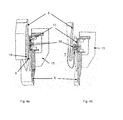
figure 4a a cross section of a prior art seal arrangement is shown in order to explain the invention. Asegmented seal 11 substantially closes theradial gap 9 between the combustorinner liner 5 and thehot gas casing 6.Figure 4b shows a similar cross section where the gap between thesegmented seal 11 and the combustorinner liner 5 has been exaggerated for purposes of explanation. The leakage air through the radial gap at theinterface 17 between adjacent seal segments hits the wall of the combustorinner liner 5 and creates a three-dimensional vortex flow 18. The vortices suck the hot gases into the overlappingregion 10 resulting in local overheating. Referring now to back tofigures 2 and3 , according to one embodiment of the invention, the combustorinner liner 5 is provided with at least oneopening 20 in the region between twoadjacent segments segmented seal 11. The at least oneopening 20 in the combustorinner liner 5 is located preferably directly opposite the gap at theinterface 17 between thesegments opening 20 allows the leaked compressed air to flow though the wall of the combustorinner liner 5 into thehot gas passage 6. As the leakage air flows directly into the hot gas path, vortex formation in the overlappingregion 10 of the combustorinner liner 5 and thehot gas casing 6 is minimized. Therefore local overheating in this region is prevented. Furthermore, the provision of the at least oneopening 20 allows the leakage air to flow into and mix with the axially flowinghot gas 7. This provides additional cooling of themetal casings casings - The
segmented seal 11 is made up of a plurality of segments which surround the combustorinner liner 5 in the circumferential direction, whereby at least oneopening 20 in the combustorinner liner 5 is respectively provided in the region of, and preferably directly opposite, eachinterface 17 between adjacent seal segments. The at least oneopening 20 may be in the form of a plurality ofholes 21 extending radially through the combustorinner liner 5. The leaking compressed air would in this case be directed radially into the axially flowinghot gases 7, thereby increasing turbulence and mixing and thus cooling of the hot gases flowing through the combustorinner liner 5. Theholes 21 may however have an axial and/or circumferential component, which would encourage film cooling of the combustor inner liner. - Alternatively the opening is in the form of a slot extending in the axial direction.
- The
holes 21 or slot should not extend further in the axial direction than the width of thesegmented seal 11 in the axial direction. - The cross-sectional area of the at least one
opening 20 is preferably designed such that the mass flow through theopening 20 is equal to the leakage flow rate through theinterface 17 between two adjacent seal segments opposite theopening 20. - The invention is applicable to all seal arrangements whereby a conduit is made from two sections with an axially overlapping portion, whereby a seal is required to seal a radial gap between the two sections at the overlapping portion. Particularly, the description when referring to a combustor inner liner and hot gas casing is not limited thereto, but to a first and second casing accordingly forming a passageway.
- The preceding description of the embodiments according to the present invention serves only an illustrative purpose and should not be considered to limit the scope of the invention. Particularly, in view of the preferred embodiments, different changes and modifications in the form and details can be made without departing from the scope of the invention. Accordingly the disclosure of the current invention should not be limiting. The disclosure of the current invention should instead serve to clarify the scope of the invention which is set forth in the following claims.
-
- 1
- Seal arrangement
- 2
- Turbine
- 3
- Combustion chamber
- 4
- Annular channel
- 5
- First casing
- 6
- Second casing
- 7
- Hot gas flow passage
- 8
- Compressed air flow
- 9
- Radial gap
- 10
- Overlapping region
- 11
- Segmented seal
- 12
- Silo combustor
- 13
- First seal segment
- 14
- Second seal segment
- 15
- Hook
- 16
- Radial direction
- 17
- Interfaces between segments
- 18
- Vortex flow
- 19
- End portion
- 20
- At least one opening
- 21
- Holes
Claims (10)
- A seal arrangement (1) for a silo combustor comprising a first casing (5) forming a passageway (7) for a gas and a second casing (6) forming a passageway (7) for a gas, whereby an end portion (19) of the first casing (5) is positioned radially inside of an end portion of the second casing (6), the two casings (5, 6) forming an overlapping region (10), whereby a segmented seal (11) is positioned to seal a radial gap (9) formed between the first casing (5) and the second casing (6) in the overlapping region (10), characterized in that the first casing (5) is provided with at least one opening (20) in the region between two adjacent segments (13, 14) of the segmented seal (11).
- A seal arrangement (1) according to claim 1, characterized in that the at least one opening (20) is formed by a plurality of holes (21) or a slot.
- A seal arrangement (1) according to claim 1, characterized in that the at least one opening (20) is directly opposite a gap between two adjacent segments (13, 14) of the segmented seal (11).
- A seal arrangement (1) according to claims 1 or 2, characterized in that the at least one opening (20) is only located in an axially extending region corresponding to the width of the segmented seal (11) in an axial direction.
- A seal arrangement according (1) to claim 1, characterized in that the at least one opening (20) is a hole or a series of holes (21) which extend through the first casing (5) in a radial direction.
- A seal arrangement according (1) to claim 1, characterized in that the at least one opening (20) is a hole or a series of holes (21) which extend through the first casing (5) in radial and axial directions.
- A seal arrangement (1) according to claim 1, characterized in that the first casing (5) and/or the second casing (6) is made out of metal.
- A seal arrangement (1) according to claim 1, characterized in that the segmented seal (11) is a belt seal comprising a plurality of connected segments (13, 14) and a spring for tightening the belt seal in the circumferential direction.
- A seal arrangement (1) according to one of the preceding claims, characterized in that the cross-sectional area of the at least one opening (20) is such that a mass flow of gas through the opening (20) is equal to a leakage flow rate through the gap between two adjacent segments (13, 14).
- A silo combustor (12) comprising a seal arrangement (1) according to any of the preceding claims, whereby the first casing (5) is formed by a combustor inner liner and the second casing (6) is formed by a hot gas casing.
Applications Claiming Priority (1)
| Application Number | Priority Date | Filing Date | Title |
|---|---|---|---|
| CH18772010 | 2010-11-09 |
Publications (2)
| Publication Number | Publication Date |
|---|---|
| EP2450533A1 true EP2450533A1 (en) | 2012-05-09 |
| EP2450533B1 EP2450533B1 (en) | 2016-03-30 |
Family
ID=43608084
Family Applications (1)
| Application Number | Title | Priority Date | Filing Date |
|---|---|---|---|
| EP11186408.8A Not-in-force EP2450533B1 (en) | 2010-11-09 | 2011-10-24 | Seal arrangement |
Country Status (8)
| Country | Link |
|---|---|
| US (1) | US9243505B2 (en) |
| EP (1) | EP2450533B1 (en) |
| KR (1) | KR101574489B1 (en) |
| CA (1) | CA2756371C (en) |
| ES (1) | ES2579237T3 (en) |
| MY (1) | MY163553A (en) |
| PE (1) | PE20121038A1 (en) |
| TW (1) | TWI507603B (en) |
Families Citing this family (1)
| Publication number | Priority date | Publication date | Assignee | Title |
|---|---|---|---|---|
| US10689994B2 (en) | 2016-03-31 | 2020-06-23 | General Electric Company | Seal assembly to seal corner leaks in gas turbine |
Citations (3)
| Publication number | Priority date | Publication date | Assignee | Title |
|---|---|---|---|---|
| US20050262845A1 (en) * | 2004-05-28 | 2005-12-01 | Martling Vincent C | Combustion liner having improved cooling and sealing |
| EP2058475A2 (en) * | 2007-11-09 | 2009-05-13 | United Technologies Corporation | Cooled transition piece of a gas turbine engine and corresponding gas turbine engine |
| US20100077761A1 (en) * | 2008-09-30 | 2010-04-01 | General Electric Company | Impingement cooled combustor seal |
Family Cites Families (7)
| Publication number | Priority date | Publication date | Assignee | Title |
|---|---|---|---|---|
| US5560198A (en) * | 1995-05-25 | 1996-10-01 | United Technologies Corporation | Cooled gas turbine engine augmentor fingerseal assembly |
| US5957463A (en) | 1997-03-14 | 1999-09-28 | Ishikawa Gasket Co., Ltd. | Metal laminate gasket with irregular size seal ring |
| JP3831362B2 (en) | 2003-06-10 | 2006-10-11 | 日本電信電話株式会社 | Communication apparatus and communication method |
| US7788932B2 (en) | 2005-08-23 | 2010-09-07 | Mitsubishi Heavy Industries, Ltd. | Seal structure for gas turbine combustor |
| JP4310345B2 (en) | 2007-01-09 | 2009-08-05 | 石川ガスケット株式会社 | Metal laminated cylinder head gasket |
| ATE472046T1 (en) | 2007-09-24 | 2010-07-15 | Alstom Technology Ltd | SEAL IN GAS TURBINE |
| US8166764B2 (en) | 2008-07-21 | 2012-05-01 | United Technologies Corporation | Flow sleeve impingement cooling using a plenum ring |
-
2011
- 2011-10-24 EP EP11186408.8A patent/EP2450533B1/en not_active Not-in-force
- 2011-10-24 ES ES11186408.8T patent/ES2579237T3/en active Active
- 2011-10-27 CA CA2756371A patent/CA2756371C/en not_active Expired - Fee Related
- 2011-11-02 MY MYPI2011005278A patent/MY163553A/en unknown
- 2011-11-03 US US13/288,094 patent/US9243505B2/en not_active Expired - Fee Related
- 2011-11-08 KR KR1020110115831A patent/KR101574489B1/en not_active Expired - Fee Related
- 2011-11-08 TW TW100140739A patent/TWI507603B/en not_active IP Right Cessation
- 2011-11-09 PE PE2011001931A patent/PE20121038A1/en not_active Application Discontinuation
Patent Citations (3)
| Publication number | Priority date | Publication date | Assignee | Title |
|---|---|---|---|---|
| US20050262845A1 (en) * | 2004-05-28 | 2005-12-01 | Martling Vincent C | Combustion liner having improved cooling and sealing |
| EP2058475A2 (en) * | 2007-11-09 | 2009-05-13 | United Technologies Corporation | Cooled transition piece of a gas turbine engine and corresponding gas turbine engine |
| US20100077761A1 (en) * | 2008-09-30 | 2010-04-01 | General Electric Company | Impingement cooled combustor seal |
Also Published As
| Publication number | Publication date |
|---|---|
| MY163553A (en) | 2017-09-29 |
| CA2756371A1 (en) | 2012-05-09 |
| ES2579237T3 (en) | 2016-08-08 |
| CA2756371C (en) | 2016-02-23 |
| KR101574489B1 (en) | 2015-12-04 |
| TW201235552A (en) | 2012-09-01 |
| US20120122045A1 (en) | 2012-05-17 |
| US9243505B2 (en) | 2016-01-26 |
| TWI507603B (en) | 2015-11-11 |
| PE20121038A1 (en) | 2012-08-30 |
| EP2450533B1 (en) | 2016-03-30 |
| KR20120049828A (en) | 2012-05-17 |
Similar Documents
| Publication | Publication Date | Title |
|---|---|---|
| US11098606B2 (en) | Sliding seal | |
| US9880059B2 (en) | Gas turbine exhaust diffuser mounted blade path thermocouple probe | |
| US8240974B2 (en) | Cold air buffer supply tube | |
| US20060082074A1 (en) | Circumferential feather seal | |
| US11365641B2 (en) | Bifurcated sliding seal | |
| CN104344426A (en) | System for providing fuel to a combustor | |
| US20140044529A1 (en) | Sealing of the flow channel of a turbomachine | |
| US9032735B2 (en) | Combustor and a method for assembling the combustor | |
| US8393154B2 (en) | Fuel delivery system with reduced heat transfer to fuel manifold seal | |
| CN105917082B (en) | Seal assembly for gap between outlet sections of adjacent transition ducts in a gas turbine engine | |
| CA2756371C (en) | Seal arrangement | |
| CN103573416B (en) | Sealing member | |
| US20160160667A1 (en) | Discourager seal for a turbine engine | |
| EP2653663A2 (en) | Seal for a turbine system | |
| US9416679B2 (en) | Borescope assembly and method of installing borescope plugs | |
| US20180142892A1 (en) | System and method for impingement cooling of turbine system components | |
| CN112840105B (en) | Sealing of a turbine | |
| EP2530385A2 (en) | Turbomachine combustor assembly including a liner stop |
Legal Events
| Date | Code | Title | Description |
|---|---|---|---|
| PUAI | Public reference made under article 153(3) epc to a published international application that has entered the european phase |
Free format text: ORIGINAL CODE: 0009012 |
|
| AK | Designated contracting states |
Kind code of ref document: A1 Designated state(s): AL AT BE BG CH CY CZ DE DK EE ES FI FR GB GR HR HU IE IS IT LI LT LU LV MC MK MT NL NO PL PT RO RS SE SI SK SM TR |
|
| AX | Request for extension of the european patent |
Extension state: BA ME |
|
| 17P | Request for examination filed |
Effective date: 20121102 |
|
| 17Q | First examination report despatched |
Effective date: 20131121 |
|
| RIC1 | Information provided on ipc code assigned before grant |
Ipc: F01D 11/04 20060101ALI20150902BHEP Ipc: F23R 3/60 20060101ALI20150902BHEP Ipc: F01D 9/02 20060101AFI20150902BHEP |
|
| GRAP | Despatch of communication of intention to grant a patent |
Free format text: ORIGINAL CODE: EPIDOSNIGR1 |
|
| INTG | Intention to grant announced |
Effective date: 20151013 |
|
| GRAS | Grant fee paid |
Free format text: ORIGINAL CODE: EPIDOSNIGR3 |
|
| GRAA | (expected) grant |
Free format text: ORIGINAL CODE: 0009210 |
|
| AK | Designated contracting states |
Kind code of ref document: B1 Designated state(s): AL AT BE BG CH CY CZ DE DK EE ES FI FR GB GR HR HU IE IS IT LI LT LU LV MC MK MT NL NO PL PT RO RS SE SI SK SM TR |
|
| REG | Reference to a national code |
Ref country code: GB Ref legal event code: FG4D |
|
| REG | Reference to a national code |
Ref country code: CH Ref legal event code: EP |
|
| REG | Reference to a national code |
Ref country code: AT Ref legal event code: REF Ref document number: 785636 Country of ref document: AT Kind code of ref document: T Effective date: 20160415 |
|
| REG | Reference to a national code |
Ref country code: IE Ref legal event code: FG4D |
|
| REG | Reference to a national code |
Ref country code: DE Ref legal event code: R096 Ref document number: 602011024551 Country of ref document: DE |
|
| REG | Reference to a national code |
Ref country code: LT Ref legal event code: MG4D |
|
| PG25 | Lapsed in a contracting state [announced via postgrant information from national office to epo] |
Ref country code: NO Free format text: LAPSE BECAUSE OF FAILURE TO SUBMIT A TRANSLATION OF THE DESCRIPTION OR TO PAY THE FEE WITHIN THE PRESCRIBED TIME-LIMIT Effective date: 20160630 Ref country code: GR Free format text: LAPSE BECAUSE OF FAILURE TO SUBMIT A TRANSLATION OF THE DESCRIPTION OR TO PAY THE FEE WITHIN THE PRESCRIBED TIME-LIMIT Effective date: 20160701 Ref country code: HR Free format text: LAPSE BECAUSE OF FAILURE TO SUBMIT A TRANSLATION OF THE DESCRIPTION OR TO PAY THE FEE WITHIN THE PRESCRIBED TIME-LIMIT Effective date: 20160330 Ref country code: FI Free format text: LAPSE BECAUSE OF FAILURE TO SUBMIT A TRANSLATION OF THE DESCRIPTION OR TO PAY THE FEE WITHIN THE PRESCRIBED TIME-LIMIT Effective date: 20160330 |
|
| REG | Reference to a national code |
Ref country code: NL Ref legal event code: MP Effective date: 20160330 |
|
| REG | Reference to a national code |
Ref country code: ES Ref legal event code: FG2A Ref document number: 2579237 Country of ref document: ES Kind code of ref document: T3 Effective date: 20160808 |
|
| REG | Reference to a national code |
Ref country code: AT Ref legal event code: MK05 Ref document number: 785636 Country of ref document: AT Kind code of ref document: T Effective date: 20160330 |
|
| RAP2 | Party data changed (patent owner data changed or rights of a patent transferred) |
Owner name: GENERAL ELECTRIC TECHNOLOGY GMBH |
|
| PG25 | Lapsed in a contracting state [announced via postgrant information from national office to epo] |
Ref country code: LT Free format text: LAPSE BECAUSE OF FAILURE TO SUBMIT A TRANSLATION OF THE DESCRIPTION OR TO PAY THE FEE WITHIN THE PRESCRIBED TIME-LIMIT Effective date: 20160330 Ref country code: LV Free format text: LAPSE BECAUSE OF FAILURE TO SUBMIT A TRANSLATION OF THE DESCRIPTION OR TO PAY THE FEE WITHIN THE PRESCRIBED TIME-LIMIT Effective date: 20160330 Ref country code: SE Free format text: LAPSE BECAUSE OF FAILURE TO SUBMIT A TRANSLATION OF THE DESCRIPTION OR TO PAY THE FEE WITHIN THE PRESCRIBED TIME-LIMIT Effective date: 20160330 Ref country code: RS Free format text: LAPSE BECAUSE OF FAILURE TO SUBMIT A TRANSLATION OF THE DESCRIPTION OR TO PAY THE FEE WITHIN THE PRESCRIBED TIME-LIMIT Effective date: 20160330 |
|
| PG25 | Lapsed in a contracting state [announced via postgrant information from national office to epo] |
Ref country code: NL Free format text: LAPSE BECAUSE OF FAILURE TO SUBMIT A TRANSLATION OF THE DESCRIPTION OR TO PAY THE FEE WITHIN THE PRESCRIBED TIME-LIMIT Effective date: 20160330 |
|
| REG | Reference to a national code |
Ref country code: DE Ref legal event code: R082 Ref document number: 602011024551 Country of ref document: DE Representative=s name: RUEGER | ABEL PATENT- UND RECHTSANWAELTE, DE Ref country code: DE Ref legal event code: R082 Ref document number: 602011024551 Country of ref document: DE Representative=s name: RUEGER ABEL PATENTANWAELTE PARTGMBB, DE Ref country code: DE Ref legal event code: R082 Ref document number: 602011024551 Country of ref document: DE Representative=s name: RUEGER, BARTHELT & ABEL, DE Ref country code: DE Ref legal event code: R081 Ref document number: 602011024551 Country of ref document: DE Owner name: GENERAL ELECTRIC TECHNOLOGY GMBH, CH Free format text: FORMER OWNER: ALSTOM TECHNOLOGY LTD., BADEN, CH Ref country code: DE Ref legal event code: R082 Ref document number: 602011024551 Country of ref document: DE Representative=s name: RUEGER ABEL PATENT- UND RECHTSANWAELTE, DE |
|
| PG25 | Lapsed in a contracting state [announced via postgrant information from national office to epo] |
Ref country code: EE Free format text: LAPSE BECAUSE OF FAILURE TO SUBMIT A TRANSLATION OF THE DESCRIPTION OR TO PAY THE FEE WITHIN THE PRESCRIBED TIME-LIMIT Effective date: 20160330 Ref country code: IS Free format text: LAPSE BECAUSE OF FAILURE TO SUBMIT A TRANSLATION OF THE DESCRIPTION OR TO PAY THE FEE WITHIN THE PRESCRIBED TIME-LIMIT Effective date: 20160730 Ref country code: PL Free format text: LAPSE BECAUSE OF FAILURE TO SUBMIT A TRANSLATION OF THE DESCRIPTION OR TO PAY THE FEE WITHIN THE PRESCRIBED TIME-LIMIT Effective date: 20160330 |
|
| PG25 | Lapsed in a contracting state [announced via postgrant information from national office to epo] |
Ref country code: AT Free format text: LAPSE BECAUSE OF FAILURE TO SUBMIT A TRANSLATION OF THE DESCRIPTION OR TO PAY THE FEE WITHIN THE PRESCRIBED TIME-LIMIT Effective date: 20160330 Ref country code: RO Free format text: LAPSE BECAUSE OF FAILURE TO SUBMIT A TRANSLATION OF THE DESCRIPTION OR TO PAY THE FEE WITHIN THE PRESCRIBED TIME-LIMIT Effective date: 20160330 Ref country code: PT Free format text: LAPSE BECAUSE OF FAILURE TO SUBMIT A TRANSLATION OF THE DESCRIPTION OR TO PAY THE FEE WITHIN THE PRESCRIBED TIME-LIMIT Effective date: 20160801 Ref country code: CZ Free format text: LAPSE BECAUSE OF FAILURE TO SUBMIT A TRANSLATION OF THE DESCRIPTION OR TO PAY THE FEE WITHIN THE PRESCRIBED TIME-LIMIT Effective date: 20160330 Ref country code: SK Free format text: LAPSE BECAUSE OF FAILURE TO SUBMIT A TRANSLATION OF THE DESCRIPTION OR TO PAY THE FEE WITHIN THE PRESCRIBED TIME-LIMIT Effective date: 20160330 Ref country code: SM Free format text: LAPSE BECAUSE OF FAILURE TO SUBMIT A TRANSLATION OF THE DESCRIPTION OR TO PAY THE FEE WITHIN THE PRESCRIBED TIME-LIMIT Effective date: 20160330 |
|
| PG25 | Lapsed in a contracting state [announced via postgrant information from national office to epo] |
Ref country code: BE Free format text: LAPSE BECAUSE OF FAILURE TO SUBMIT A TRANSLATION OF THE DESCRIPTION OR TO PAY THE FEE WITHIN THE PRESCRIBED TIME-LIMIT Effective date: 20160330 |
|
| REG | Reference to a national code |
Ref country code: DE Ref legal event code: R097 Ref document number: 602011024551 Country of ref document: DE |
|
| PG25 | Lapsed in a contracting state [announced via postgrant information from national office to epo] |
Ref country code: DK Free format text: LAPSE BECAUSE OF FAILURE TO SUBMIT A TRANSLATION OF THE DESCRIPTION OR TO PAY THE FEE WITHIN THE PRESCRIBED TIME-LIMIT Effective date: 20160330 |
|
| PLBE | No opposition filed within time limit |
Free format text: ORIGINAL CODE: 0009261 |
|
| STAA | Information on the status of an ep patent application or granted ep patent |
Free format text: STATUS: NO OPPOSITION FILED WITHIN TIME LIMIT |
|
| PGFP | Annual fee paid to national office [announced via postgrant information from national office to epo] |
Ref country code: ES Payment date: 20161026 Year of fee payment: 6 |
|
| 26N | No opposition filed |
Effective date: 20170103 |
|
| PG25 | Lapsed in a contracting state [announced via postgrant information from national office to epo] |
Ref country code: SI Free format text: LAPSE BECAUSE OF FAILURE TO SUBMIT A TRANSLATION OF THE DESCRIPTION OR TO PAY THE FEE WITHIN THE PRESCRIBED TIME-LIMIT Effective date: 20160330 |
|
| REG | Reference to a national code |
Ref country code: CH Ref legal event code: PL |
|
| REG | Reference to a national code |
Ref country code: IE Ref legal event code: MM4A |
|
| REG | Reference to a national code |
Ref country code: FR Ref legal event code: ST Effective date: 20170630 |
|
| PG25 | Lapsed in a contracting state [announced via postgrant information from national office to epo] |
Ref country code: FR Free format text: LAPSE BECAUSE OF NON-PAYMENT OF DUE FEES Effective date: 20161102 Ref country code: LI Free format text: LAPSE BECAUSE OF NON-PAYMENT OF DUE FEES Effective date: 20161031 Ref country code: CH Free format text: LAPSE BECAUSE OF NON-PAYMENT OF DUE FEES Effective date: 20161031 |
|
| PG25 | Lapsed in a contracting state [announced via postgrant information from national office to epo] |
Ref country code: LU Free format text: LAPSE BECAUSE OF NON-PAYMENT OF DUE FEES Effective date: 20161024 |
|
| PG25 | Lapsed in a contracting state [announced via postgrant information from national office to epo] |
Ref country code: IE Free format text: LAPSE BECAUSE OF NON-PAYMENT OF DUE FEES Effective date: 20161024 |
|
| PGFP | Annual fee paid to national office [announced via postgrant information from national office to epo] |
Ref country code: DE Payment date: 20171027 Year of fee payment: 7 |
|
| PGFP | Annual fee paid to national office [announced via postgrant information from national office to epo] |
Ref country code: IT Payment date: 20171024 Year of fee payment: 7 Ref country code: GB Payment date: 20171027 Year of fee payment: 7 |
|
| PG25 | Lapsed in a contracting state [announced via postgrant information from national office to epo] |
Ref country code: CY Free format text: LAPSE BECAUSE OF FAILURE TO SUBMIT A TRANSLATION OF THE DESCRIPTION OR TO PAY THE FEE WITHIN THE PRESCRIBED TIME-LIMIT Effective date: 20160330 Ref country code: HU Free format text: LAPSE BECAUSE OF FAILURE TO SUBMIT A TRANSLATION OF THE DESCRIPTION OR TO PAY THE FEE WITHIN THE PRESCRIBED TIME-LIMIT; INVALID AB INITIO Effective date: 20111024 |
|
| PG25 | Lapsed in a contracting state [announced via postgrant information from national office to epo] |
Ref country code: MC Free format text: LAPSE BECAUSE OF FAILURE TO SUBMIT A TRANSLATION OF THE DESCRIPTION OR TO PAY THE FEE WITHIN THE PRESCRIBED TIME-LIMIT Effective date: 20160330 Ref country code: TR Free format text: LAPSE BECAUSE OF FAILURE TO SUBMIT A TRANSLATION OF THE DESCRIPTION OR TO PAY THE FEE WITHIN THE PRESCRIBED TIME-LIMIT Effective date: 20160330 Ref country code: MK Free format text: LAPSE BECAUSE OF FAILURE TO SUBMIT A TRANSLATION OF THE DESCRIPTION OR TO PAY THE FEE WITHIN THE PRESCRIBED TIME-LIMIT Effective date: 20160330 Ref country code: MT Free format text: LAPSE BECAUSE OF NON-PAYMENT OF DUE FEES Effective date: 20161031 |
|
| PG25 | Lapsed in a contracting state [announced via postgrant information from national office to epo] |
Ref country code: BG Free format text: LAPSE BECAUSE OF FAILURE TO SUBMIT A TRANSLATION OF THE DESCRIPTION OR TO PAY THE FEE WITHIN THE PRESCRIBED TIME-LIMIT Effective date: 20160330 |
|
| PG25 | Lapsed in a contracting state [announced via postgrant information from national office to epo] |
Ref country code: AL Free format text: LAPSE BECAUSE OF FAILURE TO SUBMIT A TRANSLATION OF THE DESCRIPTION OR TO PAY THE FEE WITHIN THE PRESCRIBED TIME-LIMIT Effective date: 20160330 |
|
| REG | Reference to a national code |
Ref country code: ES Ref legal event code: FD2A Effective date: 20181221 |
|
| PG25 | Lapsed in a contracting state [announced via postgrant information from national office to epo] |
Ref country code: ES Free format text: LAPSE BECAUSE OF NON-PAYMENT OF DUE FEES Effective date: 20171025 |
|
| REG | Reference to a national code |
Ref country code: DE Ref legal event code: R119 Ref document number: 602011024551 Country of ref document: DE |
|
| GBPC | Gb: european patent ceased through non-payment of renewal fee |
Effective date: 20181024 |
|
| PG25 | Lapsed in a contracting state [announced via postgrant information from national office to epo] |
Ref country code: DE Free format text: LAPSE BECAUSE OF NON-PAYMENT OF DUE FEES Effective date: 20190501 |
|
| PG25 | Lapsed in a contracting state [announced via postgrant information from national office to epo] |
Ref country code: IT Free format text: LAPSE BECAUSE OF NON-PAYMENT OF DUE FEES Effective date: 20181024 Ref country code: GB Free format text: LAPSE BECAUSE OF NON-PAYMENT OF DUE FEES Effective date: 20181024 |