EP2450515A1 - Door control device for vehicles - Google Patents
Door control device for vehicles Download PDFInfo
- Publication number
- EP2450515A1 EP2450515A1 EP10793781A EP10793781A EP2450515A1 EP 2450515 A1 EP2450515 A1 EP 2450515A1 EP 10793781 A EP10793781 A EP 10793781A EP 10793781 A EP10793781 A EP 10793781A EP 2450515 A1 EP2450515 A1 EP 2450515A1
- Authority
- EP
- European Patent Office
- Prior art keywords
- signal
- door
- control unit
- output
- input
- Prior art date
- Legal status (The legal status is an assumption and is not a legal conclusion. Google has not performed a legal analysis and makes no representation as to the accuracy of the status listed.)
- Withdrawn
Links
Images




Classifications
-
- E—FIXED CONSTRUCTIONS
- E05—LOCKS; KEYS; WINDOW OR DOOR FITTINGS; SAFES
- E05F—DEVICES FOR MOVING WINGS INTO OPEN OR CLOSED POSITION; CHECKS FOR WINGS; WING FITTINGS NOT OTHERWISE PROVIDED FOR, CONCERNED WITH THE FUNCTIONING OF THE WING
- E05F15/00—Power-operated mechanisms for wings
- E05F15/40—Safety devices, e.g. detection of obstructions or end positions
-
- E—FIXED CONSTRUCTIONS
- E05—LOCKS; KEYS; WINDOW OR DOOR FITTINGS; SAFES
- E05F—DEVICES FOR MOVING WINGS INTO OPEN OR CLOSED POSITION; CHECKS FOR WINGS; WING FITTINGS NOT OTHERWISE PROVIDED FOR, CONCERNED WITH THE FUNCTIONING OF THE WING
- E05F15/00—Power-operated mechanisms for wings
- E05F15/60—Power-operated mechanisms for wings using electrical actuators
- E05F15/603—Power-operated mechanisms for wings using electrical actuators using rotary electromotors
-
- E—FIXED CONSTRUCTIONS
- E05—LOCKS; KEYS; WINDOW OR DOOR FITTINGS; SAFES
- E05F—DEVICES FOR MOVING WINGS INTO OPEN OR CLOSED POSITION; CHECKS FOR WINGS; WING FITTINGS NOT OTHERWISE PROVIDED FOR, CONCERNED WITH THE FUNCTIONING OF THE WING
- E05F15/00—Power-operated mechanisms for wings
- E05F15/60—Power-operated mechanisms for wings using electrical actuators
- E05F15/603—Power-operated mechanisms for wings using electrical actuators using rotary electromotors
- E05F15/632—Power-operated mechanisms for wings using electrical actuators using rotary electromotors for horizontally-sliding wings
- E05F15/655—Power-operated mechanisms for wings using electrical actuators using rotary electromotors for horizontally-sliding wings specially adapted for vehicle wings
-
- E—FIXED CONSTRUCTIONS
- E05—LOCKS; KEYS; WINDOW OR DOOR FITTINGS; SAFES
- E05Y—INDEXING SCHEME ASSOCIATED WITH SUBCLASSES E05D AND E05F, RELATING TO CONSTRUCTION ELEMENTS, ELECTRIC CONTROL, POWER SUPPLY, POWER SIGNAL OR TRANSMISSION, USER INTERFACES, MOUNTING OR COUPLING, DETAILS, ACCESSORIES, AUXILIARY OPERATIONS NOT OTHERWISE PROVIDED FOR, APPLICATION THEREOF
- E05Y2201/00—Constructional elements; Accessories therefor
- E05Y2201/40—Motors; Magnets; Springs; Weights; Accessories therefor
- E05Y2201/43—Motors
- E05Y2201/434—Electromotors; Details thereof
-
- E—FIXED CONSTRUCTIONS
- E05—LOCKS; KEYS; WINDOW OR DOOR FITTINGS; SAFES
- E05Y—INDEXING SCHEME ASSOCIATED WITH SUBCLASSES E05D AND E05F, RELATING TO CONSTRUCTION ELEMENTS, ELECTRIC CONTROL, POWER SUPPLY, POWER SIGNAL OR TRANSMISSION, USER INTERFACES, MOUNTING OR COUPLING, DETAILS, ACCESSORIES, AUXILIARY OPERATIONS NOT OTHERWISE PROVIDED FOR, APPLICATION THEREOF
- E05Y2400/00—Electronic control; Electrical power; Power supply; Power or signal transmission; User interfaces
- E05Y2400/10—Electronic control
- E05Y2400/30—Electronic control of motors
-
- E—FIXED CONSTRUCTIONS
- E05—LOCKS; KEYS; WINDOW OR DOOR FITTINGS; SAFES
- E05Y—INDEXING SCHEME ASSOCIATED WITH SUBCLASSES E05D AND E05F, RELATING TO CONSTRUCTION ELEMENTS, ELECTRIC CONTROL, POWER SUPPLY, POWER SIGNAL OR TRANSMISSION, USER INTERFACES, MOUNTING OR COUPLING, DETAILS, ACCESSORIES, AUXILIARY OPERATIONS NOT OTHERWISE PROVIDED FOR, APPLICATION THEREOF
- E05Y2400/00—Electronic control; Electrical power; Power supply; Power or signal transmission; User interfaces
- E05Y2400/10—Electronic control
- E05Y2400/40—Control units therefor
-
- E—FIXED CONSTRUCTIONS
- E05—LOCKS; KEYS; WINDOW OR DOOR FITTINGS; SAFES
- E05Y—INDEXING SCHEME ASSOCIATED WITH SUBCLASSES E05D AND E05F, RELATING TO CONSTRUCTION ELEMENTS, ELECTRIC CONTROL, POWER SUPPLY, POWER SIGNAL OR TRANSMISSION, USER INTERFACES, MOUNTING OR COUPLING, DETAILS, ACCESSORIES, AUXILIARY OPERATIONS NOT OTHERWISE PROVIDED FOR, APPLICATION THEREOF
- E05Y2400/00—Electronic control; Electrical power; Power supply; Power or signal transmission; User interfaces
- E05Y2400/10—Electronic control
- E05Y2400/40—Control units therefor
- E05Y2400/41—Control units therefor for multiple motors
- E05Y2400/415—Control units therefor for multiple motors for multiple wings
- E05Y2400/42—Control units therefor for multiple motors for multiple wings for multiple openings
-
- E—FIXED CONSTRUCTIONS
- E05—LOCKS; KEYS; WINDOW OR DOOR FITTINGS; SAFES
- E05Y—INDEXING SCHEME ASSOCIATED WITH SUBCLASSES E05D AND E05F, RELATING TO CONSTRUCTION ELEMENTS, ELECTRIC CONTROL, POWER SUPPLY, POWER SIGNAL OR TRANSMISSION, USER INTERFACES, MOUNTING OR COUPLING, DETAILS, ACCESSORIES, AUXILIARY OPERATIONS NOT OTHERWISE PROVIDED FOR, APPLICATION THEREOF
- E05Y2400/00—Electronic control; Electrical power; Power supply; Power or signal transmission; User interfaces
- E05Y2400/10—Electronic control
- E05Y2400/50—Fault detection
- E05Y2400/502—Fault detection of components
-
- E—FIXED CONSTRUCTIONS
- E05—LOCKS; KEYS; WINDOW OR DOOR FITTINGS; SAFES
- E05Y—INDEXING SCHEME ASSOCIATED WITH SUBCLASSES E05D AND E05F, RELATING TO CONSTRUCTION ELEMENTS, ELECTRIC CONTROL, POWER SUPPLY, POWER SIGNAL OR TRANSMISSION, USER INTERFACES, MOUNTING OR COUPLING, DETAILS, ACCESSORIES, AUXILIARY OPERATIONS NOT OTHERWISE PROVIDED FOR, APPLICATION THEREOF
- E05Y2800/00—Details, accessories and auxiliary operations not otherwise provided for
- E05Y2800/40—Physical or chemical protection
-
- E—FIXED CONSTRUCTIONS
- E05—LOCKS; KEYS; WINDOW OR DOOR FITTINGS; SAFES
- E05Y—INDEXING SCHEME ASSOCIATED WITH SUBCLASSES E05D AND E05F, RELATING TO CONSTRUCTION ELEMENTS, ELECTRIC CONTROL, POWER SUPPLY, POWER SIGNAL OR TRANSMISSION, USER INTERFACES, MOUNTING OR COUPLING, DETAILS, ACCESSORIES, AUXILIARY OPERATIONS NOT OTHERWISE PROVIDED FOR, APPLICATION THEREOF
- E05Y2800/00—Details, accessories and auxiliary operations not otherwise provided for
- E05Y2800/40—Physical or chemical protection
- E05Y2800/424—Physical or chemical protection against unintended use, e.g. protection against vandalism or sabotage
-
- E—FIXED CONSTRUCTIONS
- E05—LOCKS; KEYS; WINDOW OR DOOR FITTINGS; SAFES
- E05Y—INDEXING SCHEME ASSOCIATED WITH SUBCLASSES E05D AND E05F, RELATING TO CONSTRUCTION ELEMENTS, ELECTRIC CONTROL, POWER SUPPLY, POWER SIGNAL OR TRANSMISSION, USER INTERFACES, MOUNTING OR COUPLING, DETAILS, ACCESSORIES, AUXILIARY OPERATIONS NOT OTHERWISE PROVIDED FOR, APPLICATION THEREOF
- E05Y2900/00—Application of doors, windows, wings or fittings thereof
- E05Y2900/50—Application of doors, windows, wings or fittings thereof for vehicles
- E05Y2900/51—Application of doors, windows, wings or fittings thereof for vehicles for railway cars or mass transit vehicles
-
- E—FIXED CONSTRUCTIONS
- E05—LOCKS; KEYS; WINDOW OR DOOR FITTINGS; SAFES
- E05Y—INDEXING SCHEME ASSOCIATED WITH SUBCLASSES E05D AND E05F, RELATING TO CONSTRUCTION ELEMENTS, ELECTRIC CONTROL, POWER SUPPLY, POWER SIGNAL OR TRANSMISSION, USER INTERFACES, MOUNTING OR COUPLING, DETAILS, ACCESSORIES, AUXILIARY OPERATIONS NOT OTHERWISE PROVIDED FOR, APPLICATION THEREOF
- E05Y2900/00—Application of doors, windows, wings or fittings thereof
- E05Y2900/50—Application of doors, windows, wings or fittings thereof for vehicles
- E05Y2900/53—Type of wing
- E05Y2900/531—Doors
Definitions
- the direction switching unit either directly outputs the motor encoder signal or inverts the signal and then outputs the signal based on the two different signals from the upper system (for example, the first signal is a transmission signal and the second signal is a contact signal), an unintentional operation to open the door for the vehicle can be more reliably prevented whenever one of the signals from the upper system is faulty.
- the drive unit 300 is provided with a triplet of pairs of power devices (such as IGBTs or power MOSFETs) capable of supplying power from a power source corresponding to a U-phase, a V-phase, and a W-phase of the DC motor 400 in accordance with the signal from the control unit 200, each corresponding to a phase of the DC motor 400.
- a triplet of pairs of power devices such as IGBTs or power MOSFETs
- the control unit 200 stores a control program capable of outputting only a motor drive signal that matches the motor drive signal input into the drive unit 300 when the operation is to close the door (in other words, only one type of signal).
- the electrical relay can use a contactless relay in addition to a contact relay.
- the control signal SIG1 is of the transmission format and the control signal SIG2 is a contact signal
- both the control signal SIG1 and the control signal SIG2 may be contact signals, or both may be of the transmission format.
- the door control device 100b for rail cars further includes a handedness setting DIP switch (DIPSW) circuit 800.
- the handedness setting DIP switch circuit 800 has a DIP switch 810, and is intended to set the direction in which the door is closed.
- the DIP switch 810 is set to one of either ON (+24V) or OFF (0V), and then the corresponding handedness signal KSIG is passed on to the control unit 200.
- the corresponding handedness signal KSIG is also then passed on to the exclusive OR circuits 650U, 650V, and 650W by the control unit 200.
- FIG. 7 is a flow chart serving to describe an example of the operation of the control unit 200 according to the third embodiment.
- the control unit reads out the content of the handedness setting DIP switch (DIPSW) circuit 800 (step S11).
- a handedness signal (KSIG) is then output based on the content that has been read out (step S12).
- KSIG handedness signal
- control signal SIG3 for switching the direction switcher 600 to the door-opening direction is output from the control unit 200 (step S22).
- the control signal SIG3 is input into the AND circuit 630 of the direction switcher 600.
- the control signal SIG2 is also directly input from the upper system to the AND circuit 630.
- the control signal SIG2 includes a speed detection signal (5 km/h detection signal), an unlock-all signal, a permission-to-open signal, or the like.
- control unit 200 compares the corrected encoder input signals H1, H2, and H3 with the signals H11, H21, and H31 from the encoder monitors 710U, 710V, and 710W (step S23).
- the control unit 200 when even a part of the corrected encoder input signals H1, H2, and H3 does not match the inverted forms of the signals H11, H21, and H31 from the encoder monitors 710U, 710V, and 710W, the control unit 200 returns to the process in step S21 without moving the door. Note that in such a case, the output of the control unit 200 may be made to report to the exterior of the door control device 100b a signal that any of the direction switcher 600, the sensors 510U, 510V, and 510W, or the encoder monitor 700 have failed.
- the object is a comparison with the inverted forms of the signals H11, H21, and H31 from the encoder monitors 710U, 710V, and 710W, but when the setting status of the handedness signal KSIG is High, the configuration is that the comparison is performed without any inversion.
- a "close command” refers to a transmission-format signal that is contained in the control signal SIG1 and instructs that the door is to be closed.
- control signal SIG3 for switching the direction switcher 600 to the door-closing direction is output from the control unit 200 (step S27).
- the AND circuit 630 selects the non-insertion signal line sides of the relays 620U, 620V, and 620W.
- the encoder signals of the sensors 510U, 510V, and 510W are thereby input via the exclusive OR circuits 650U, 650V, and 650W to the control unit 200 as corrected encoder input signals H1, H2, and H3.
- control unit 200 determines whether or not the door is in a completely close position (step S29).
- the control unit 200 repeats the process from step S28.
- control unit 200 returns to step S21.
- step S23 may be inserted in between the process in step S27 and the process in step S28, to authenticate the failure or the like of the apparatus.
- the door control device 100c for rail cars further includes a handedness setting DIP switch (DIPSW) circuit 800c.
- the handedness setting DIP switch circuit 800c has a DIP switch and is intended to set the direction in which the door is closed.
- the handedness signal KSIG can be passed on without passing via the control unit 200. As a result, there will not be any effect from a failure or the like of the control unit 200.
- the handedness setting DIP switch (DIPSW) circuit 800 is additionally provided, it is possible to support the opposite handedness. That is, in the case of two opening doors, this operation is performed by having the pair of doors moving in opposite directions for the opening operations and the closing operations, and therefore the same can be set using the handedness setting DIP switch (DIPSW) circuit 800.
- the door control devices 100, 100a, 100b, and 100c for rail cars correspond to the door control device for vehicles;
- the DC motor 400 corresponds to the brushless motor;
- the drive unit 300 corresponds to the drive unit;
- the motor encoder 500 corresponds to the motor encoder;
- the control signal SIG1 and the control signal SIG2 correspond to the signals from the upper system;
- the control unit 200 corresponds to the control unit;
- the control signal SIG1 corresponds to the first signal;
- the control signal SIG2 corresponds to the second signal;
- the direction switchers 600, 600a, 600b, and 600c correspond to the direction switching unit;
- the relays 620U, 620V, and 620W and the relays 670U, 670V, and 670W correspond to the electrical relay;
- the exclusive logical circuits 640U, 640V, and 640W correspond to the exclusive logical circuits of the direction switching unit;
- the exclusive logical circuits 650U, 650V, and 650W correspond
- a preferred embodiment of the present invention is as described above, but the present invention is not to be limited only thereto. It will be understood that there are various additional possible embodiments that will not depart from the gist and scope of the present invention. Further, operations and effects from the configuration of the present invention are described in these embodiments, but these operations and effects are an example and are not meant to limit the present invention.
Landscapes
- Power-Operated Mechanisms For Wings (AREA)
Abstract
Description
- The present invention relates to a door control device for vehicles, for controlling the opening and closing of the side doors of a vehicle.
- General examples of vehicles having doors on the side of the vehicle include automobiles or rail cars. Of these, rail cars for conveying passengers are provided with a sliding door serving as a side door found on the side of the vehicle, in order to allow general passengers to board and disembark. Devices utilizing compressed air were conventionally used as a source of drive for such sliding doors, but in recent years it has become commonplace to use devices utilizing an electric motor controlled by a microcomputer (Patent Document 1). Lately, electric sliding doors have often been employed as side doors in automobiles.
- The side door opening and closing device for rail cars recited in
Patent Document 1 uses a brushless direct current motor as an electric motor in order to improve maintainability. -
- [PTL 1] Japanese Unexamined Patent Application Publication No.
2002-309849 - Thus, in order to ensure the safety of the passengers or the crew, the side door on the side opposite the platform will not open while the rail car is in transit, or even stalled, whenever a control device for the electric motor or the like experiences failure or is operated in error. The same is true of automobiles.
- In order to prevent such unintentional opening of the door, when, for example, the electric motor is a brushed direct current motor, consideration is given to providing a relay for opening and closing based on signals from an upper system of the rail car or automobile, within the current pathway for rotating the brushed direct current motor in the direction for opening the door. Further, when the electric motor is a brushless direct current motor, consideration is given to causing a relay for selecting whether or not to supply current to the brushless direct current motor to open or close based on the signals from the upper system of the rail car or automobile.
- However, in the former case, although the door will not open unintentionally whenever a control device for the electric motor or the like experiences failure or is operated in error, implementation is not possible without a brushed motor, and problems remain in terms of maintainability.
On the other hand, in the latter case, because the door can be moved in both the opening and closing direction when the relay is operated so as to feed current to the brushless direct current motor, it is assumed that the door may sometimes open unintentionally whenever a control device for the electric motor or the like experiences failure or is operated in error, even though the probability is very low, because the time required to operate the relay to feed current is short. - It is therefore an object of the present invention to provide a door control device for vehicles wherein the reliability of the control for opening and closing the side doors for a vehicle can be maintained and improved.
- The door control device for vehicles according to the present invention includes a brushless motor that drives the opening and closing of a door; a motor encoder that detects the position of the brushless motor; a direction switching unit that either directly outputs a motor encoder signal or inverts the signal and then outputs the signal based on a signal from an upper system; and a control unit provided so as to be able to output only drive signals of a pattern that matches drive signals input to a drive unit when the door is driven to close, and configured so as to output drive signals based on the signals output by the direction switching unit, based on a signal from an upper system.
Note that an "upper system" signifies a door command control system provided to each rail car train, a centralized management system, or a primary control device governing the control of an entire automobile; the control unit is provided to each door of the vehicle. - As described above, the control unit is configured so as to be able to output only drive signals that match the drive signals input to the drive unit when the door is driven to close, and therefore the control unit is unable to drive to open the door whenever the control unit experiences a failure or is operated in error, unless the direction switching unit is switched - that is, unless the signal from the upper system is faulty. Therefore, an unintentional operation to open the door for the vehicle can be reliably prevented. As a result, the reliability of the control for opening and closing the door for the vehicle can be maintained and improved.
- In a preferred configuration, the signals from the upper system comprise a first signal that is input to the control unit, and a second signal that is input to the direction switching unit and is different from the first signal, and the direction switching unit is preferably configured to either directly output a motor encoder signal or invert the signal and then output the signal based on the signal that is output from the control unit, which is based on the first signal, as well as based on the second signal.
- According to such a configuration, because the direction switching unit either directly outputs the motor encoder signal or inverts the signal and then outputs the signal based on the two different signals from the upper system (for example, the first signal is a transmission signal and the second signal is a contact signal), an unintentional operation to open the door for the vehicle can be more reliably prevented whenever one of the signals from the upper system is faulty.
- The direction switching unit may be constituted of an exclusive OR circuit into which the signal output from the control unit and the second signal are input, and from which the input signals are output to the control unit.
- According to such a configuration, because a failure due to a mechanical part will not occur, the failure rate can be reduced without incurring costs.
- The direction switching unit is provided with an inverting circuit into which the motor encoder signal is input, and an electrical relay that is switched so as to output either the output signal of the inverting circuit or the motor encoder signal, and the electrical relay may be configured such that the output signal of the inverting circuit is output when the door is to be driven to open.
- According to such a configuration, an unintentional operation to open the door for the vehicle can be more reliably prevented, because the drive to close the door is unaffected even when the inverting circuit fails. A contribution is further made to the on-time transit of the rail car, as well.
- In a preferred configuration, the control unit is configured such that the motor encoder signal input into the direction switching unit can be input thereinto, a comparison then being made between the signal output by the direction switching unit and the input motor encoder signal.
- According to such a configuration, the differences between the motor encoder signal input into the control unit and the signal output from the direction switching unit to the control unit are authenticated in consideration of signal from the upper system, by all the respective phases (for example, three phases) ; the situation is determined to be normal when all the phases match, and the direction switching unit can be judged to have failed when even a part of the phases does not match. Therefore, an unintentional operation to open the door for the vehicle can be more reliably prevented.
- The door control device for vehicles may be further provided with a handedness switching unit that sets the direction to close the door, in between the direction switching unit and the control unit.
- In such a case, because the door control device for vehicles is further provided with the handedness switching unit that sets the direction to close the door, in between the direction switching unit and the control unit, it is possible to support the opposite handedness with a single type of door control device for vehicles. That is, in the case of a single opening door, whether or not the direction in which the door is closed is the direction to the front of the vehicle is determined according to the specification of the vehicle, but because the same can be set using the handedness switching unit, there is no need to manufacture or maintain etc., an opposite-handedness-door control device, and therefore the effort required for management in the factory can be reduced.
- The handedness switching unit may comprise a switching switch and an exclusive OR circuit for switching the handedness direction.
- In such a case, because the handedness switching unit comprises the switching switch and the exclusive OR circuit for switching the handedness direction, the configuration can be simplified and the door control device for vehicles can be rendered smaller.
- [
-
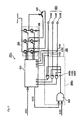
FIG. 1 ] A schematic structural diagram depicting an example of a door control device for rail cars according to a first embodiment. - [
FIG. 2 ] A flowchart serving to describe an example of the operation of the control unit. - [
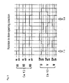
FIG. 3 ] A schematic diagram depicting an example of the relationship between the encoder signal and the motor drive signal. - [
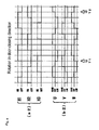
FIG. 4 ] A schematic diagram depicting an example of the relationship between the encoder signal and the motor drive signal. - [
FIG. 5 ] A schematic structural diagram depicting an example of a door control device for rail cars according to a second embodiment. - [
FIG. 6 ] A schematic structural diagram depicting an example of a door control device for rail cars according to a third embodiment. - [
FIG. 7 ] A flowchart serving to describe an example of the operation of the control unit. - [
FIG. 8 ] A schematic structural diagram depicting an example of a door control device for rail cars according to a fourth embodiment. -
- 100, 100a door control device for rail cars
- 200 control unit
- 300 drive unit
- 400 DC motor
- 500 motor encoder
- 600, 600a direction switcher
- 610U, 610V, 610W inverting circuit (direction switching unit) 620U, 620V, 620W relay
- 640U, 640V, 640W exclusive logical circuit (direction switching unit)
- 650U, 650V, 650W exclusive logical circuit (handedness switching unit)
- 660U, 660V, 660W inverting circuit (handedness switching unit) SIG1, SIG2, SIG3 control signal
- 800 handedness setting DIP switch (DIPSW)
circuit 810 DIP switch - The following is a description of embodiments according to the present invention. In the following embodiments, the door control device for vehicles is described taking the example of a door control device for a rail car having a sliding door provided for when general passengers are being conveyed. Note that the present invention is not to be limited to rail cars, and can also be applied to automobiles and other types of vehicles having doors.
-
FIG. 1 is a schematic structural diagram depicting an example of adoor control device 100 for a rail car according to a first embodiment of the present invention. - Each passenger embarkation port of the rail car is provided with the
door control device 100 for rail cars. As depicted inFIG. 1 , thedoor control device 100 for rail cars includes a control unit (a "local control unit", or "LCU") 200, adrive unit 300, a three-phase direct current brushless motor (hereinafter called a DC motor) 400, amotor encoder 500, adirection switcher 600, and anencoder monitor 700. Note that a door locking switch (DLS) is typically provided to the door control device; the lock is unlocked when the door is to be opened, and is locked when the door has been closed. In the embodiments below, a description of the door locking switch has been omitted. - The
drive unit 300 is provided with a triplet of pairs of power devices (such as IGBTs or power MOSFETs) capable of supplying power from a power source corresponding to a U-phase, a V-phase, and a W-phase of theDC motor 400 in accordance with the signal from thecontrol unit 200, each corresponding to a phase of theDC motor 400. - A power transmission device (not shown) capable of opening and closing the door for the rail car is connected to the
DC motor 400. Examples of such power transmission devices include a rack-and-pinion mechanism, a ball screw mechanism, a belt mechanism, or the like. The rotation of theDC motor 400 in a given direction is able to perform the operation to open the door, and the rotation of theDC motor 400 in the opposite direction thereto is able to perform the operation to close the door. - Three Hall elements (a
sensor 510U, asensor 510V, and asensor 510W) provided in order to detect the magnetic phase of the DC motor are used as themotor encoder 500. The rotation of theDC motor 400 can be detected by using themotor encoder 500. - Next, the
direction switcher 600 includes invertingcircuits circuit 630. A control signal SIG1, which is a transmission-format signal sent from the upper system by an RS-485 line, is passed to the ANDcircuit 630 via thecontrol unit 200 as a control signal SIG3, which is a digital signal, and a control signal SIG2, which is a contact signal sent from the upper system, is further passed thereto. Also, therelays control unit 200 and by receiving the open/closed status of the door from thecontrol unit 200. - Then, a signal line from the
sensor 510U branches into two, each connecting to two inputs of therelay 620U. The invertingcircuit 610U is inserted into one of these branched signal lines.
Similarly, the signal line from thesensor 510V branches into two, each connecting to two inputs of therelay 620V. Theinverting circuit 610V being inserted into one of these branched signal lines, the signal line from thesensor 510W then branches into two, and each connects to two inputs of therelay 620W. The invertingcircuit 610W is inserted into one of these branched signal lines. Below, a signal line into which an inverting circuit has been inserted is referred to as an inverter line, and a signal line into which an inverting circuit has not been inserted is referred to as a non-insertion signal line. - The
relays circuit 630. The output side of therelays control unit 200. Note that the configuration of this embodiment is such that a non-insertion signal line is selected when the operation is to close the door, and an inverter line is selected when the operation is to open the door. - Subsequently, the inside of the
control unit 200 stores a control program that is capable of outputting only a motor drive signal that matches a motor drive signal input into thedrive unit 300 when the operation is to close the door. An unintentional operation to open the door is therefore prevented even when thecontrol unit 200 experiences a failure or is operated in error, because the door, as thecontrol unit 200, is only able to output a motor drive signal in the direction for closing. Note that a more detailed description will be provided later for the relationship between the motor drive signal and the signal from the encoder input to thecontrol unit 200. - Next,
FIG. 2 is a flow chart serving to describe an example of the operation of thecontrol unit 200. - As depicted in
FIG. 2 , thecontrol unit 200 is on stand-by until an open command is received from the upper system (step S1). Herein, an "open command" refers to a transmission-format signal that is contained in the control signal SIG1, and instructs that the door is to be opened. - Next, when an open command is received (step S1: Yes), the control signal SIG3 for switching the
direction switcher 600 to the door-opening direction is output from the control unit 200 (step S2). Herein, the control signal SIG3 is input into the ANDcircuit 630 of thedirection switcher 600. A control signal SIG2 from the upper system is also directly input into the ANDcircuit 630. Herein, the control signal SIG2 includes a speed detection signal (5 km/h detection signal), an unlock-all signal, a permission-to-open signal, or the like. - Herein, the control signal SIG3 is an ON signal that indicates door opening; when the control signal SIG2 indicates the direction for opening the door, the AND
circuit 630 selects the inverter line sides of therelays FIG. 1 ). In such a case, thesensors control unit 200 as corrected encoder input signals H1, H2, and H3. - On the other hand, when either one of the control signal SIG3 and the control signal SIG2 does not indicate door opening, the output of the AND
circuit 630 is such that the non-insertion signal line sides of therelays sensors control unit 200 as corrected encoder input signals H1, H2, and H3. - In such a case, as will be described later, the
control unit 200 controls theDC motor 400 so as to rotate in the direction in which the door is closed when the signals from thesensors control unit 200 experiences a failure or is operated in error, because the motor drive signals for the door are output only in the closing direction. - Next, when both signals of the control signal SIG3 and the control signal SIG2 indicate door opening, the
control unit 200 compares the corrected encoder input signals H1, H2, and H3 with the signals H11, H21, and H31 from the encoder monitors 710U, 710V, and 710W (step S3). - Herein, the
control unit 200 returns to the process in step S1 without moving the door when even a part of the corrected encoder input signals H1, H2, and H3 do not match the inverted forms of the signals H11, H21, and H31 from the encoder monitors 710U, 710V, and 710W. Note that in such a case, the output of thecontrol unit 200 may make it possible to visually confirm, from the exterior of thedoor control device 100 for rail cars, a signal in which any of thedirection switcher 600, thesensors encoder monitor 700 has failed. This failure signal may be transmitted to the upper system. - When the corrected encoder input signals H1, H2, and H3 completely match the inverted forms of the signals H11, H21, and H31 from the encoder monitors 710U, 710V, and 710W in all phases, the
control unit 200 runs the aforementioned motor control program stored therein and outputs a motor drive signal to thedrive unit 300 based on the corrected encoder input signals H1, H2, and H3. Further, theDC motor 400 being driven by thedrive unit 300 and the encoder signal being detected by themotor encoder 500, thecontrol unit 200 continues to control thedrive unit 300 based on the corrected encoder signals (step S4). - Subsequently, the
control unit 200 determines whether or not the door is in a completely open position (step S5). Herein, thecontrol unit 200 repeats the process from step S4 when the determination is that the door is not in a completely open position. - On the other hand, when the determination is that the door is in a completely open position, the
control unit 200 remains on stand-by until a close command is received from the upper system (step S6). Herein, a "close command" is a transmission-format signal that is contained in the control signal SIG1, which instructs that the door is to be closed. - Next, the control signal SIG3 for switching the
direction switcher 600 to the door-closing direction is output from the control unit 200 (step S7).
Herein, when the control signal SIG3 is an OFF signal indicating door closing, or alternatively when the control signal SIG2 indicates the direction in which the door is closed, the ANDcircuit 630 selects the non-insertion signal line sides of therelays sensors control unit 200 as the corrected encoder input signals H1, H2, and H3, without being changed. - The
control unit 200 runs the motor control program stored therein and outputs a motor drive signal to thedrive unit 300 based on the input corrected encoder input signals H1, H2, and H3. Further, theDC motor 400 being driven by thedrive unit 300 and the encoder signal being detected by themotor encoder 500, thecontrol unit 200 continuously controls thedrive unit 300 based on the encoder signal (step S8). - Subsequently, the
control unit 200 determines whether or not the door is in a completely close position (step S9). Herein, thecontrol unit 200 repeats the process from step S8 when the determination is that the door is not in a completely close position. - On the other hand, the
control unit 200 returns to step S1 when the determination is that the door is in a completely close position. - Note that in the above-described flow chart (
FIG. 2 ), the process in step S3 may be inserted in between the process in step S7 and the process in step S8, to authenticate the failure or the like of the apparatus. - Next,
FIGS. 3 and4 are schematic diagrams depicting an example of the relationship between the motor drive signal and the encoder signal input to the control unit 200 - namely, the corrected encoder input signal.FIG. 3 depicts a corrected encoder input signal and motor drive signal for the door-opening direction, andFIG. 4 depicts a corrected encoder input signal and motor drive signal for the door-closing direction. - As depicted in
FIG. 3(a1) , the corrected encoder input signals H1, H2, and H3 repeat ON and OFF when the rotation is in the door-opening direction. Also, inFIG. 3(b1) , the drive signals U, V, and W for thedrive unit 300 repeat HIGH, OFF, LOW, and OFF. - On the other hand, as depicted in
FIG. 4(a2) , the corrected encoder input signals H1, H2, and H3 repeat ON and OFF when the rotation is in the door-opening direction. Also, inFig. 4(b2) , the drive signals U, V, and W for thedrive unit 300 repeat HIGH, OFF, LOW, and OFF. - Herein, as depicted in
FIGS. 3 and4 , from timing T1 to timing T2, whenFIG. 3(a1) andFIG. 4(a2) are compared, inverting the ON and OFF timing of one matches the ON and OFF timing of the other.
Also, the HIGH, OFF, and LOW relationships inFIGS. 3(b1) and4(b2) from timing T1 to timing T2 match completely. - From the above, when the
sensors drive unit 300 that drives theDC motor 400. Therefore, as described above, thecontrol unit 200 stores a control program capable of outputting only a motor drive signal that matches the motor drive signal input into thedrive unit 300 when the operation is to close the door (in other words, only one type of signal). Because the configuration is thus, whenever thecontrol unit 200 experiences a failure or is operated in error, an unintentional operation to open the door is prevented unless thedirection switcher 600 is switched, because the door, serving as thecontrol unit 200, can only output a motor drive signal in the closing direction. Moreover, reliability is high because thedirection switcher 600 is not switched such that the operation opens the door until both of the control signals SIG1 and SIG2, which are in different formats, meet certain conditions. - Next, another example of the
door control device 100 for rail cars according to the present invention will be described. The following is a description of the points of difference from thedoor control device 100 for rail cars depicted inFIG. 1 . -
FIG. 5 is a schematic structural diagram depicting and example of adoor control device 100a for rail cars according to a second embodiment of the present invention. - As depicted in
FIG. 5 , thedoor control device 100a for rail cars includes adirection switcher 600a instead of thedirection switcher 600 inFIG. 1 . - The
direction switcher 600a comprises exclusivelogical circuits circuit 630. The control signal SIG1 passed from the upper system is input to the ANDcircuit 630 via thecontrol unit 200 as the control signal SIG3, and furthermore the control signal SIG2 from the upper system is also directly input thereinto. The output from the ANDcircuit 630 is respectively input into the input of one of the exclusivelogical circuits - The signal line from the
sensor 510U is input to another input of the exclusivelogical circuit 640U. Similarly, the signal line from thesensor 510V is input to another input of the exclusivelogical circuit 640V, and the signal line from thesensor 510W is input to another input of the exclusive logical circuit 640W. The output sides of the exclusivelogical circuits control unit 200, and the corrected encoder input signals H1, H2, and H3, which are the output of the exclusivelogical circuits control unit 200. - In such a case, in the
door control device 100a for rail cars, as in thedoor control device 100 for rail cars, the signals from thesensors control unit 200 as corrected encoder input signals H1, H2, and H3, unless all the output from the ANDcircuit 630 is ON. Accordingly, unless door-opening signals from the control signal SIG2 and the control signal SIG3 are entered into the ANDcircuit 630, thedrive unit 300 will not be driven so as to open the door; rather, thedrive unit 300 will be driven so as to close the door. - As described above, in the
door control device 100a for rail cars according to the present invention, an unintentional operation to open the door can be reliably prevented even when thecontrol unit 200 experiences an abnormality or a failure, because as thecontrol unit 200, motor drive signals can only be output in the closing direction. - Also, the
direction switcher 600 in thedoor control device 100 for rail cars according to the first embodiment, being constituted of the invertingcircuits relays circuits direction switcher 600a in thedoor control device 100a for rail cars according to the second embodiment, being constituted of the exclusivelogical circuits - Furthermore, disparities between the motor encoder signals H11, H21, and H31 detected by the
encoder monitor 700 and the corrected encoder input signals H1, H2, and H3 are authenticated taking into account of the switched status of thedirection switchers direction switchers direction switchers direction switchers - Note that this embodiment has been described taking the example of the three-phase direct
current brushless motor 400, but there is not limitation thereto, and the motor having any other desired number of phases may be used. Further, in the first embodiment, the motor encoder signals H11, H21, and H31 are made to pass through the invertingcircuits - Next, a description will be provided for yet another example of the
door control device 100 for rail cars according to the present invention. In adoor control device 100b for rail cars in the third embodiment, the description provided is for thedoor control device 100b that is capable of supporting an opposite handedness of a rail car side door - that is, a door that is closed in different directions. The following is a description of the points of difference from thedoor control device 100 for rail cars and thedoor control device 100a for rail cars depicted inFIGS. 1 to 5 . -
FIG. 6 is a schematic structural diagram depicting an example of thedoor control device 100b for rail cars according to the third embodiment of the present invention. - As depicted in
FIG. 6 , thedoor control device 100b for rail cars includes adirection switcher 600b instead of thedirection switchers direction switcher 600b comprises the invertingcircuits relays circuit 630, as well as exclusive ORcircuits - The
door control device 100b for rail cars further includes a handedness setting DIP switch (DIPSW)circuit 800. The handedness settingDIP switch circuit 800 has aDIP switch 810, and is intended to set the direction in which the door is closed. TheDIP switch 810 is set to one of either ON (+24V) or OFF (0V), and then the corresponding handedness signal KSIG is passed on to thecontrol unit 200. The corresponding handedness signal KSIG is also then passed on to the exclusive ORcircuits control unit 200. - The control signal SIG1, which is a transmission-format signal that has been sent from the upper system by the RS-485 line, is passed to the AND
circuit 630 via thecontrol unit 200 as the control signal SIG3, which is a digital signal; the control signal SIG2, which is a contact signal sent from the upper system, is also passed thereto. Therelays circuits - As depicted in
FIG. 6 , the signal line from thesensor 510U branches into two, each connecting to the two inputs of therelay 620U. The invertingcircuit 610U is then inserted into one of these branched signal lines.
Similarly, the signal line from thesensor 510V branches into two, each connecting to the two inputs of therelay 620V. Theinverting circuit 610V is inserted into one of these branched signal lines; the signal line from thesensor 510W branches into two, each connecting to the two inputs of therelay 620W. The invertingcircuit 610W is inserted into one of these branched signal lines. Below, equivalent toFIG. 1 , a signal line into which an inverting circuit has been inserted is referred to as an inverter line, and a signal line into which an inverting circuit has not been inserted is referred to as a non-insertion signal line. - The
relays circuit 630. The output sides of therelays circuits
The handedness signal is also connected to one of the two inputs of the exclusive ORcircuits circuits control unit 200 based on the handedness signal KSIG and therelays - That is, in the
door control device 100b for rail cars, the direction of movement of the door (handedness direction) can be changed using the handedness signal KSIG, and therefore the management man-hours in the factory and the like of the door control device can be reduced without necessitating the manufacture or management of an opposite-handedness-door control device - that is, two different kinds of control devices. - Next,
FIG. 7 is a flow chart serving to describe an example of the operation of thecontrol unit 200 according to the third embodiment. - As depicted in
FIG. 7 , the control unit reads out the content of the handedness setting DIP switch (DIPSW) circuit 800 (step S11). A handedness signal (KSIG) is then output based on the content that has been read out (step S12). In particular, it is possible to control either one of left or right door opening by switching theDIP switch 810 of the handedness setting DIP switch (DIPSW)circuit 800. - Subsequently, the
control unit 200 remains on stand-by until an open command is received from the upper system (step S21). Herein, an "open command" refers to a transmission-format signal that is contained in the control signal SIG1, and which instructs to open the door. - Next, when an open command is received (step S21: Yes), the control signal SIG3 for switching the
direction switcher 600 to the door-opening direction is output from the control unit 200 (step S22). Herein, the control signal SIG3 is input into the ANDcircuit 630 of thedirection switcher 600. The control signal SIG2 is also directly input from the upper system to the ANDcircuit 630. Herein, the control signal SIG2 includes a speed detection signal (5 km/h detection signal), an unlock-all signal, a permission-to-open signal, or the like. - Herein, when the control signal SIG3 is an ON signal indicating door opening and the control signal SIG2 indicates the direction for opening the door, the AND
circuit 630 selects the inverter line sides of therelays FIG. 6 ). In such a case, thesensors circuits circuits circuits control unit 200 as the corrected encoder input signals H1, H2, and H3. - On the other hand, when the control signal SIG3 and the control signal SIG2 do not indicate door opening, the output of the AND
circuit 630 is such that the non-insertion signal line sides of therelays sensors circuits control unit 200 as the corrected encoder input signals H1, H2, and H3. - In such a case, as will be described later, when the signals from the
sensors control unit 200 controls theDC motor 400 to rotate in the direction in which the door is closed. - Next, when all the signals of the control signal SIG3 and the control signal SIG2 indicate door opening, the
control unit 200 compares the corrected encoder input signals H1, H2, and H3 with the signals H11, H21, and H31 from the encoder monitors 710U, 710V, and 710W (step S23). - Herein, when even a part of the corrected encoder input signals H1, H2, and H3 does not match the inverted forms of the signals H11, H21, and H31 from the encoder monitors 710U, 710V, and 710W, the
control unit 200 returns to the process in step S21 without moving the door. Note that in such a case, the output of thecontrol unit 200 may be made to report to the exterior of thedoor control device 100b a signal that any of thedirection switcher 600, thesensors encoder monitor 700 have failed. - When the corrected encoder input signals H1, H2, and H3 completely match the inverted forms of the signals H11, H21, and H31 from the encoder monitors 710U, 710V, and 710W in all phases, the
control unit 200 runs the aforementioned motor control program stored therein, and outputs a motor drive signal to thedrive unit 300 based on the corrected encoder input signals H1, H2, and H3. Further, theDC motor 400 being driven by thedrive unit 300 and the encoder signal being detected by themotor encoder 500, thecontrol unit 200 continuously controls thedrive unit 300 based on the corrected encoder signal (step S24). Note that herein, when the setting status of the handedness signal KSIG is Low, the object is a comparison with the inverted forms of the signals H11, H21, and H31 from the encoder monitors 710U, 710V, and 710W, but when the setting status of the handedness signal KSIG is High, the configuration is that the comparison is performed without any inversion. - Subsequently, the
control unit 200 determines whether or not the door is in a completely open position (step S25). Herein, thecontrol unit 200 repeats the process from step S24 when the determination is that the door is not in a completely open position. - On the other hand, when the determination is that the door is in a completely open position, the
control unit 200 remains on stand-by until a close command is received from the upper system (step S26). Herein, a "close command" refers to a transmission-format signal that is contained in the control signal SIG1 and instructs that the door is to be closed. - Next, the control signal SIG3 for switching the
direction switcher 600 to the door-closing direction is output from the control unit 200 (step S27). Herein, when the control signal SIG3 is an OFF signal indicating door closing, or alternatively when the control signal SIG2 indicates the direction in which the door is closed, the ANDcircuit 630 selects the non-insertion signal line sides of therelays sensors circuits control unit 200 as corrected encoder input signals H1, H2, and H3. - The
control unit 200 runs the motor control program stored therein and outputs a motor drive signal to thedrive unit 300 based on the input corrected encoder input signals H1, H2, and H3. Also, theDC motor 400 being driven by thedrive unit 300 and the encoder signal being detected by themotor encoder 500, thecontrol unit 200 continuously controls thedrive unit 300 based on the encoder signal (step S28). Note that herein, the setting status of the handedness signal KSIG has been recited as being Low, but when the setting status is High, the corrected encoder input signals H1, H2, and H3 are inverted and then input. - Subsequently, the
control unit 200 determines whether or not the door is in a completely close position (step S29). Herein, when the determination is that the door is not in a completely close position, thecontrol unit 200 repeats the process from step S28. - On the other hand, when the determination is that the door is in a completely close position, the
control unit 200 returns to step S21. - Note that in the flow chart described above (
FIG. 7 ), the process in step S23 may be inserted in between the process in step S27 and the process in step S28, to authenticate the failure or the like of the apparatus. - Next, yet another example of the
door control device 100 for rail cars according to the present invention will be described. The following is a description of the points of difference from thedoor control devices FIGS. 1 to 7 . -
FIG. 8 is a schematic structural diagram depicting an example of adoor control device 100c for rail cars according to the fourth embodiment of the present invention. - As depicted in
FIG. 8 , thedoor control device 100c for rail cars includes adirection switcher 600c instead of thedirection switchers direction switcher 600c comprises the invertingcircuits relays circuit 630; invertingcircuits - The
door control device 100c for rail cars further includes a handedness setting DIP switch (DIPSW)circuit 800c. The handedness settingDIP switch circuit 800c has a DIP switch and is intended to set the direction in which the door is closed. In this embodiment, the handedness signal KSIG can be passed on without passing via thecontrol unit 200. As a result, there will not be any effect from a failure or the like of thecontrol unit 200. - Because the handedness setting DIP switch (DIPSW)
circuit 800 is additionally provided, it is possible to support the opposite handedness. That is, in the case of two opening doors, this operation is performed by having the pair of doors moving in opposite directions for the opening operations and the closing operations, and therefore the same can be set using the handedness setting DIP switch (DIPSW)circuit 800. Furthermore, by providing the handedness setting DIP switch (DIPSW)circuit 800, a signal of themotor encoder 500 is output either directly or inverted and then output even when thecontrol unit 200 is operated in error in the doors having different closing directions - for example, when the microcomputer erroneously recognizes an open command, and thus even when one of the signals SIG1 and SIG2 from the upper system is faulty, an unintentional operation to open the doors of the vehicle can be more reliably prevented, and the door will not open unintentionally while in transit, nor will the door of the oppose side from the platform open. Therefore, an unintentional operation to open the door of the vehicle can be reliably prevented. As a result, the reliability of the control for opening and closing the doors of the vehicle can be maintained and improved. Additionally, because there is no need to manufacture separate door control devices for each of a pair of doors, the effort required for management time during manufacture can be reduced. - In the embodiments of the present invention, the door control devices 100, 100a, 100b, and 100c for rail cars correspond to the door control device for vehicles; the DC motor 400 corresponds to the brushless motor; the drive unit 300 corresponds to the drive unit; the motor encoder 500 corresponds to the motor encoder; the control signal SIG1 and the control signal SIG2 correspond to the signals from the upper system; the control unit 200 corresponds to the control unit; the control signal SIG1 corresponds to the first signal; the control signal SIG2 corresponds to the second signal; the direction switchers 600, 600a, 600b, and 600c correspond to the direction switching unit; the relays 620U, 620V, and 620W and the relays 670U, 670V, and 670W correspond to the electrical relay; the exclusive logical circuits 640U, 640V, and 640W correspond to the exclusive logical circuits of the direction switching unit; the exclusive logical circuits 650U, 650V, and 650W correspond to the exclusive OR circuit of the handedness switching unit; the handedness setting DIP switch (DIPSW) circuit 800 corresponds to the handedness switching unit; the DIP switch 810 corresponds to the switching switch; the inverting circuits 610U, 610V, and 610W correspond to the inverting circuits of the direction switching unit; and the inverting circuits 660U, 660V, and 660W correspond to the inverting circuits of the handedness switching unit.
- A preferred embodiment of the present invention is as described above, but the present invention is not to be limited only thereto. It will be understood that there are various additional possible embodiments that will not depart from the gist and scope of the present invention. Further, operations and effects from the configuration of the present invention are described in these embodiments, but these operations and effects are an example and are not meant to limit the present invention.
Claims (7)
- A door control device for vehicles for controlling the opening and closing of a vehicle door, the device comprising:a brushless motor that drives the opening and closing of said door;a drive unit that drives said brushless motor;a motor encoder that detects the position of said brushless motor;a direction switching unit that either directly outputs a signal of said motor encoder or inverts the signal and then outputs the signal based on a signal from an upper system; anda control unit, which is provided so as to be able to output only a drive signal having a pattern that matches a pattern of a drive signal input to said drive unit when said door is driven to close,and which outputs said drive signal based on a signal output by said direction switching unit in accordance with the signal from said upper system.
- The door control device for vehicles according to claim 1, wherein
the signal from said upper system comprises a first signal input to said control unit, and a second signal that is different from said first signal and is input to said direction switching unit, and
said direction switching unit is configured so as to either directly output a signal of said motor encoder or invert the signal and then output the signal based on a signal output from said control unit based on said first signal and said second signal. - The door control device for vehicles according to claim 2, wherein said direction switching unit is constituted of an exclusive OR circuit into which said second signal and the signal that is output from said control unit are input, and from which the input signals are output to said control unit.
- The door control device for vehicles according to claim 1, wherein said direction switching unit comprises an inverting circuit into which said motor encoder signal is input, and an electrical relay that switches so as to output either of the output signal of said inverting circuit and said motor encoder signal;
and said electrical relay is configured such that the output signal from said inverting circuit is output when said door is to be driven to open. - The door control device for vehicles according to any one of claims 1 to 4, wherein said control unit is configured such that said motor encoder signal input to said direction switching unit can be input, and is configured so as to compare the signal output by said direction switching unit with said input motor encoder signal, taking into account of the signal from said upper system.
- The door control device for vehicles according to any one of claims 1 to 5, further comprising a handedness switching unit that sets a direction in which said door is closed, between said direction switching unit and said control unit.
- The door control device for vehicles according to claim 6, wherein said handedness switching unit is constituted of an exclusive OR circuit and a switching switch for switching the handedness direction.
Applications Claiming Priority (3)
| Application Number | Priority Date | Filing Date | Title |
|---|---|---|---|
| JP2009157099 | 2009-07-01 | ||
| JP2009192495 | 2009-08-21 | ||
| PCT/JP2010/003823 WO2011001604A1 (en) | 2009-07-01 | 2010-06-09 | Door control device for vehicles |
Publications (2)
| Publication Number | Publication Date |
|---|---|
| EP2450515A1 true EP2450515A1 (en) | 2012-05-09 |
| EP2450515A4 EP2450515A4 (en) | 2014-01-29 |
Family
ID=43410696
Family Applications (1)
| Application Number | Title | Priority Date | Filing Date |
|---|---|---|---|
| EP10793781.5A Withdrawn EP2450515A4 (en) | 2009-07-01 | 2010-06-09 | DOOR CONTROL DEVICE FOR VEHICLES |
Country Status (5)
| Country | Link |
|---|---|
| EP (1) | EP2450515A4 (en) |
| JP (1) | JP5300980B2 (en) |
| CN (1) | CN102472075B (en) |
| TW (1) | TWI385087B (en) |
| WO (1) | WO2011001604A1 (en) |
Families Citing this family (4)
| Publication number | Priority date | Publication date | Assignee | Title |
|---|---|---|---|---|
| CN102545747A (en) * | 2012-03-16 | 2012-07-04 | 诺丁智能科技(安徽)有限公司 | Automatic door brush motor control device |
| CN104806111A (en) * | 2015-03-25 | 2015-07-29 | 华东交通大学 | Pure hardware circuit based subway vehicle door control system |
| JP2016183523A (en) * | 2015-03-26 | 2016-10-20 | オムロンオートモーティブエレクトロニクス株式会社 | Opening/closing body control device and opening/closing body control method |
| JP7491799B2 (en) | 2020-09-25 | 2024-05-28 | ナブテスコ株式会社 | Door drive device, door drive method, and door drive program |
Family Cites Families (12)
| Publication number | Priority date | Publication date | Assignee | Title |
|---|---|---|---|---|
| JPH0467792A (en) * | 1990-07-04 | 1992-03-03 | Hitachi Ltd | Reversible rotation controller of dc motor |
| JPH0898578A (en) * | 1994-09-19 | 1996-04-12 | Shibaura Eng Works Co Ltd | DC motor drive |
| JP3779378B2 (en) * | 1996-05-09 | 2006-05-24 | ナブテスコ株式会社 | Railway vehicle side door control device |
| JPH11180303A (en) * | 1997-12-18 | 1999-07-06 | Nabco Ltd | Monitoring device for rolling stock |
| US6032416A (en) * | 1998-06-18 | 2000-03-07 | Westinghouse Air Brake Company | Transit vehicle door |
| US7032349B2 (en) * | 2000-04-27 | 2006-04-25 | Atoma International Corp. | Coreless motor door closure system for motor vehicles |
| JP3485315B2 (en) | 2001-04-17 | 2004-01-13 | 東日本トランスポ−テック株式会社 | Rail vehicle door opening and closing device |
| CN2492661Y (en) * | 2001-08-04 | 2002-05-22 | 傅海山 | Automatic door unit with brushless motor |
| JP2005048356A (en) * | 2003-07-29 | 2005-02-24 | Ykk Corp | Automatic door control method and control device |
| JP4167621B2 (en) * | 2004-05-19 | 2008-10-15 | アスモ株式会社 | Pinching detection method and vehicle movable body drive device |
| JP2005336804A (en) * | 2004-05-26 | 2005-12-08 | Nabtesco Corp | Self-propelled automatic door |
| JP2007215281A (en) * | 2006-02-08 | 2007-08-23 | Mitsuba Corp | Drive control device of brushless motor |
-
2010
- 2010-06-09 JP JP2011520758A patent/JP5300980B2/en not_active Expired - Fee Related
- 2010-06-09 EP EP10793781.5A patent/EP2450515A4/en not_active Withdrawn
- 2010-06-09 CN CN201080028434.2A patent/CN102472075B/en not_active Expired - Fee Related
- 2010-06-09 WO PCT/JP2010/003823 patent/WO2011001604A1/en not_active Ceased
- 2010-06-10 TW TW099118934A patent/TWI385087B/en not_active IP Right Cessation
Also Published As
| Publication number | Publication date |
|---|---|
| TW201107171A (en) | 2011-03-01 |
| CN102472075A (en) | 2012-05-23 |
| EP2450515A4 (en) | 2014-01-29 |
| JPWO2011001604A1 (en) | 2012-12-10 |
| HK1168137A1 (en) | 2012-12-21 |
| TWI385087B (en) | 2013-02-11 |
| JP5300980B2 (en) | 2013-09-25 |
| CN102472075B (en) | 2015-03-25 |
| WO2011001604A1 (en) | 2011-01-06 |
Similar Documents
| Publication | Publication Date | Title |
|---|---|---|
| JP5117614B2 (en) | Rail vehicle door control system | |
| CN102449253B (en) | Electric door locking system using cam | |
| US20090139147A1 (en) | Method to high availability control for railway doors systems, on board system and application to accessories and surroundings of doors | |
| CN103661161B (en) | Window opening and closing controller | |
| US10844647B2 (en) | Method for operating a door module of a motor vehicle | |
| US20090100758A1 (en) | Door driving control apparatus | |
| CN103615172A (en) | Electric motor coach gate control external circuit with two-side gate opening and closing control function | |
| US20050102903A1 (en) | Door driving control apparatus | |
| JP5300980B2 (en) | Door control device for vehicle | |
| CN106292458B (en) | Shielding door control device with function of preventing accidental action and control method | |
| US20220307297A1 (en) | Control apparatus and control method | |
| JP2010208768A (en) | Door device of elevator | |
| US9912262B2 (en) | Positioning arrangement for moving an object that is to be positioned | |
| HK1168137B (en) | Door control device for vehicles | |
| US20240308561A1 (en) | Cableway with data communication between cableway controller and vehicle | |
| KR101874470B1 (en) | Cam type switchgear for drive door | |
| CN115126354A (en) | Monitoring device and monitoring method | |
| KR102624433B1 (en) | Integrated door control device for train doors | |
| CN106809237B (en) | A kind of electronic tripper of self-powered of railway locomotive switching mechanism | |
| JP7486449B2 (en) | Platform door system | |
| JP4815803B2 (en) | Door drive control device and door drive control method | |
| HK1164806B (en) | Door control system for railroad vehicle | |
| US1191968A (en) | Auxiliary control device for car-doors. | |
| JP7491799B2 (en) | Door drive device, door drive method, and door drive program | |
| JP2009167606A (en) | Sliding door control device, and sliding door apparatus equipped with the same |
Legal Events
| Date | Code | Title | Description |
|---|---|---|---|
| PUAI | Public reference made under article 153(3) epc to a published international application that has entered the european phase |
Free format text: ORIGINAL CODE: 0009012 |
|
| 17P | Request for examination filed |
Effective date: 20120103 |
|
| AK | Designated contracting states |
Kind code of ref document: A1 Designated state(s): AL AT BE BG CH CY CZ DE DK EE ES FI FR GB GR HR HU IE IS IT LI LT LU LV MC MK MT NL NO PL PT RO SE SI SK SM TR |
|
| DAX | Request for extension of the european patent (deleted) | ||
| A4 | Supplementary search report drawn up and despatched |
Effective date: 20140108 |
|
| RIC1 | Information provided on ipc code assigned before grant |
Ipc: E05F 15/00 20060101ALI20131220BHEP Ipc: B61D 19/02 20060101ALI20131220BHEP Ipc: E05F 15/14 20060101ALI20131220BHEP Ipc: E05F 15/10 20060101AFI20131220BHEP Ipc: E05F 15/20 20060101ALI20131220BHEP |
|
| 17Q | First examination report despatched |
Effective date: 20160902 |
|
| GRAP | Despatch of communication of intention to grant a patent |
Free format text: ORIGINAL CODE: EPIDOSNIGR1 |
|
| RIC1 | Information provided on ipc code assigned before grant |
Ipc: B61D 19/02 20060101ALI20170807BHEP Ipc: E05F 15/603 20150101AFI20170807BHEP Ipc: E05F 15/632 20150101ALI20170807BHEP Ipc: E05F 15/659 20150101ALI20170807BHEP |
|
| INTG | Intention to grant announced |
Effective date: 20170906 |
|
| STAA | Information on the status of an ep patent application or granted ep patent |
Free format text: STATUS: THE APPLICATION IS DEEMED TO BE WITHDRAWN |
|
| 18D | Application deemed to be withdrawn |
Effective date: 20180117 |