EP2450472B1 - Air management system for an aircraft with hardface coating on wear surface of a valve - Google Patents
Air management system for an aircraft with hardface coating on wear surface of a valve Download PDFInfo
- Publication number
- EP2450472B1 EP2450472B1 EP11187001.0A EP11187001A EP2450472B1 EP 2450472 B1 EP2450472 B1 EP 2450472B1 EP 11187001 A EP11187001 A EP 11187001A EP 2450472 B1 EP2450472 B1 EP 2450472B1
- Authority
- EP
- European Patent Office
- Prior art keywords
- hardface
- thrust
- valve
- management system
- hardface alloy
- Prior art date
- Legal status (The legal status is an assumption and is not a legal conclusion. Google has not performed a legal analysis and makes no representation as to the accuracy of the status listed.)
- Active
Links
Images

Classifications
-
- F—MECHANICAL ENGINEERING; LIGHTING; HEATING; WEAPONS; BLASTING
- F16—ENGINEERING ELEMENTS AND UNITS; GENERAL MEASURES FOR PRODUCING AND MAINTAINING EFFECTIVE FUNCTIONING OF MACHINES OR INSTALLATIONS; THERMAL INSULATION IN GENERAL
- F16K—VALVES; TAPS; COCKS; ACTUATING-FLOATS; DEVICES FOR VENTING OR AERATING
- F16K25/00—Details relating to contact between valve members and seats
- F16K25/005—Particular materials for seats or closure elements
-
- B—PERFORMING OPERATIONS; TRANSPORTING
- B64—AIRCRAFT; AVIATION; COSMONAUTICS
- B64D—EQUIPMENT FOR FITTING IN OR TO AIRCRAFT; FLIGHT SUITS; PARACHUTES; ARRANGEMENT OR MOUNTING OF POWER PLANTS OR PROPULSION TRANSMISSIONS IN AIRCRAFT
- B64D13/00—Arrangements or adaptations of air-treatment apparatus for aircraft crew or passengers, or freight space
-
- C—CHEMISTRY; METALLURGY
- C23—COATING METALLIC MATERIAL; COATING MATERIAL WITH METALLIC MATERIAL; CHEMICAL SURFACE TREATMENT; DIFFUSION TREATMENT OF METALLIC MATERIAL; COATING BY VACUUM EVAPORATION, BY SPUTTERING, BY ION IMPLANTATION OR BY CHEMICAL VAPOUR DEPOSITION, IN GENERAL; INHIBITING CORROSION OF METALLIC MATERIAL OR INCRUSTATION IN GENERAL
- C23C—COATING METALLIC MATERIAL; COATING MATERIAL WITH METALLIC MATERIAL; SURFACE TREATMENT OF METALLIC MATERIAL BY DIFFUSION INTO THE SURFACE, BY CHEMICAL CONVERSION OR SUBSTITUTION; COATING BY VACUUM EVAPORATION, BY SPUTTERING, BY ION IMPLANTATION OR BY CHEMICAL VAPOUR DEPOSITION, IN GENERAL
- C23C24/00—Coating starting from inorganic powder
- C23C24/08—Coating starting from inorganic powder by application of heat or pressure and heat
- C23C24/10—Coating starting from inorganic powder by application of heat or pressure and heat with intermediate formation of a liquid phase in the layer
- C23C24/103—Coating with metallic material, i.e. metals or metal alloys, optionally comprising hard particles, e.g. oxides, carbides or nitrides
- C23C24/106—Coating with metal alloys or metal elements only
-
- C—CHEMISTRY; METALLURGY
- C23—COATING METALLIC MATERIAL; COATING MATERIAL WITH METALLIC MATERIAL; CHEMICAL SURFACE TREATMENT; DIFFUSION TREATMENT OF METALLIC MATERIAL; COATING BY VACUUM EVAPORATION, BY SPUTTERING, BY ION IMPLANTATION OR BY CHEMICAL VAPOUR DEPOSITION, IN GENERAL; INHIBITING CORROSION OF METALLIC MATERIAL OR INCRUSTATION IN GENERAL
- C23C—COATING METALLIC MATERIAL; COATING MATERIAL WITH METALLIC MATERIAL; SURFACE TREATMENT OF METALLIC MATERIAL BY DIFFUSION INTO THE SURFACE, BY CHEMICAL CONVERSION OR SUBSTITUTION; COATING BY VACUUM EVAPORATION, BY SPUTTERING, BY ION IMPLANTATION OR BY CHEMICAL VAPOUR DEPOSITION, IN GENERAL
- C23C4/00—Coating by spraying the coating material in the molten state, e.g. by flame, plasma or electric discharge
- C23C4/18—After-treatment
-
- F—MECHANICAL ENGINEERING; LIGHTING; HEATING; WEAPONS; BLASTING
- F16—ENGINEERING ELEMENTS AND UNITS; GENERAL MEASURES FOR PRODUCING AND MAINTAINING EFFECTIVE FUNCTIONING OF MACHINES OR INSTALLATIONS; THERMAL INSULATION IN GENERAL
- F16K—VALVES; TAPS; COCKS; ACTUATING-FLOATS; DEVICES FOR VENTING OR AERATING
- F16K1/00—Lift valves or globe valves, i.e. cut-off apparatus with closure members having at least a component of their opening and closing motion perpendicular to the closing faces
- F16K1/16—Lift valves or globe valves, i.e. cut-off apparatus with closure members having at least a component of their opening and closing motion perpendicular to the closing faces with pivoted closure-members
- F16K1/18—Lift valves or globe valves, i.e. cut-off apparatus with closure members having at least a component of their opening and closing motion perpendicular to the closing faces with pivoted closure-members with pivoted discs or flaps
- F16K1/22—Lift valves or globe valves, i.e. cut-off apparatus with closure members having at least a component of their opening and closing motion perpendicular to the closing faces with pivoted closure-members with pivoted discs or flaps with axis of rotation crossing the valve member, e.g. butterfly valves
Definitions
- This disclosure generally relates to formation of wear surfaces supporting sliding or rotational movement. More particularly, this disclosure relates to a method of producing a hardface wear surface on a thrust surface of a valve, including desired material properties.
- a wear resistant coating is applied to protect sliding components and extend operational life.
- Wear resistant coatings may utilize a hardfacing alloy that is applied to contact surfaces of a sliding or rotating component.
- Application of a hardface alloy is conventionally performed utilizing puddle-weld or arc-spray methods.
- the puddle-weld method is performed manually and cannot provide consistently repeatable results.
- the arc-spray method is not efficient for more complex recessed part geometries.
- the present invention provides an air management system for an aircraft comprising: a valve plate movable for controlling airflow through a passage; a valve shaft including an axial end supporting the valve plate within the passage; and a thrust plate for controlling axial movement of the valve shaft, the thrust plate including a thrust surface in contact with the axial end of the valve shaft, the thrust surface including a hardface alloy coating formed from a hardface alloy powder melted and solidified on the thrust surface, wherein the thrust surface is recessed and at least partially surrounded by walls.
- an aircraft 10 includes an air management system 12 mounted to a support 14 within the aircraft 10.
- the example air management system 12 includes a conduit 16 that defines a passage 18 for air flow.
- a valve assembly 20 controls airflow through the passage 18 and includes a valve plate 22 mounted on a shaft 28 and rotated by an actuator 24 about an axis 26.
- the shaft 28 includes an axial end 30 that is supported by a thrust plate 32.
- the example thrust plate 32 limits movement of the shaft along the axis 26.
- the example air management system 12 is required to operate within an extreme temperature range, at high vibration levels with little or no lubrication.
- the example thrust plate 32 includes a hardface surface between abutting relative moving parts such as the interface between the axial end 30 and the thrust plate 32.
- the example thrust plate 32 includes a hardface coating 38 disposed on a thrust surface 34.
- the example thrust surface 34 is surrounded by walls 36 that correspond with a profile of the shaft 28.
- the axial end 30 of the shaft 28 abuts and rotates on the hardface coating 38 to provide the desired wear protection.
- the example hardface coating 38 is formed from a hard and wear resistant material such as a Colmonoy 6 alloy (Ni-Cr-B-Si-Fe) with a Rockwell hardness (C scale) in a range between HRC 55 and HRC 60. Moreover other alloy compounds and materials that provide the desired wear performance at the extreme temperatures could also be utilized and are within the contemplation of this disclosure.
- the example thrust plate 32 is formed from a metal material compatible with the environment in which the valve assembly 20 operates. The example metal material forming the thrust plate 32 is of hardness less than that of the hardface coating 38.
- the shaft 28 is engaged in abutting contact with the thrust surface 34 and therefore the entire thrust plate 32 does not encounter the wear experienced and is not required to be fabricated from a material capable of the wear resistance provided by the hardface coating 38.
- the hardface coating 38 is therefore formed locally on the wear prone surfaces of the thrust plate 32.
- the thrust surface 34 receives the majority of contact and therefore is provided with the hardface coating 38.
- Other applications where wear resistance is desired could utilize a hardface alloy coating on other portions of the part and are within the contemplation of this disclosure.
- the example thrust plate 32 includes the side walls 36 surrounding the recessed thrust surface 34. Access to the thrust surface 34 is therefore complicated due to the confined area in which the hardface coating 38 is required.
- an example process for locally applying the hardface coating 38 is schematically shown at 40 and includes an initial step of depositing a hardface alloy powder 42 onto the wear surface.
- the hardface alloy powder 42 is deposited on the thrust surface 34 that is recessed between the walls 36.
- the hardface alloy powder 42 settles on the thrust surface 34 and is distributed substantially evenly across the thrust surface 34.
- the hardface alloy powder 42 is then leveled out as shown in Figure 5 and prepared for heating.
- the thrust plate 32 with the hardface alloy powder 42 is placed on a level even surface within a vacuum furnace 44.
- the temperature within the vacuum furnace 44 is then raised to a first temperature that is below the melting point of the hardface alloy powder 42.
- the vacuum furnace may be backfilled with a low partial pressure of an inert gas. This may be necessary for certain hardfacing alloys containing elements which are prone to out-gassing.
- the first temperature is maintained for a desired first dwell time such that the hardface alloy powder 42 may attain thermal equilibrium.
- the specific temperature and dwell time is dependent on the specific hardface alloy powder material along with the material comprising the thrust plate 32.
- the temperature is raised to a second temperature above the liquidus temperature of the hardface alloy powder 42, but below a melting temperature of the thrust plate 32. Therefore, the hardface alloy powder 42 is heated to a molten liquid state indicated at 46 while the thrust plate 32 remains in the solid state. Accordingly, the hardface alloy powder 42 is formed from a material having a melting temperature lower than that of the material utilized to form the thrust plate 32.
- transformation of the hardface alloy powder 42 into the molten liquid hardface alloy 46 may generate surface tension. It is this surface tension that results in a slight contraction or balling up of the molten liquid hardface alloy 46 as is schematically shown.
- the edges of the molten liquid hardface alloy 46 draw inwardly away from the side walls 36 to form the doomed shape schematically shown.
- edges of the molten liquid hardface alloy 46 draw away from the side walls 36 and form an angle 56 relative to the wear thrust surface 34. In this example, the angle is approximately 110°. It should be understood that other angles may result from different material and process parameters.
- the second temperature is held for a second dwell time to provide substantially complete transformation of the hardface alloy powder 42 into molten liquid hardface alloy 46.
- the thrust plate 32 is cooled to room temperature by inert gas quenching directly from the second temperature or controlled furnace cooling to a third cooling temperature below the solidus of the hardface alloy, then gas quenching.
- the second temperature may also include a temperature range below the liquidus temperature but above the solidus temperature where incipient melting is present such that most of the hardface alloy powder 42 is changed to the liquid state. Accordingly, it is within the contemplation of the disclosed process to utilize temperatures to change the hardface alloy powder 42 into a molten material, but is not required to be at the full liquidus temperature.
- the cooling step is performed as a quench or slow cool from the second melting temperature to the third cooling temperature to solidify or freeze the molten liquid hardface alloy 46 in the shape attained in the melting step.
- the frozen or solidified material substantially retains the shape attained at the second temperature.
- a dome shape is attained, however other shapes can be attained by leveling or otherwise orientating the hardface alloy powder 42.
- the resulting frozen or solid hardface alloy 48 forms a predictable and repeatable shape that covers the desired portions of the thrust surface 34.
- the example thrust plate 32 is maintained at the third cooling temperature until a thermal equilibrium at room temperature is attained.
- the cooling process produces a dense coating of the solid hardface alloy 48 with less than 1% porosity and uniform microstructure.
- a machining step is performed to attain a desired thickness 54 of the completed hardface coating 38.
- a machine tool 52 is utilized to extend into the recess of the thrust plate 32 and machine the solid hardface alloy 48 to the desired thickness 54.
- the machine process utilized to attain the desired thickness may include any known material removal process compatible with the hardface alloy material and desired production parameters.
- the resulting hardface alloy coating 38 provides the desired wear resistant surface of the thrust plate 32.
- a subsequent heat treat may be implemented to restore thrust plate 32 mechanical properties, since the braze process may anneal or solutionize the chosen base metal.
- another example thrust plate 60 includes a recess 62 disposed below thrust surface 70 that receives a portion of the hardface alloy 64.
- a portion of the hardface alloy 64 accumulates within the recess 62 and results in a corresponding depression 66 on a top surface of the hardface alloy 64.
- the edges shown in this disclosed example of the solidified hardfaced alloy 64 forms the angle 68 during the melting process.
- the disclosed example angle and shape of the solidified hardfaced alloy 64 can be modified to provide other shapes as desired.
- the depression 66 is subsequently machined away to provide the desired smooth level wear surface.
- the hardface alloy 64 is machined away to the thrust surface 70.
- the resulting thrust surface 70 is flat and includes a desired thickness of the hardface alloy 64 that is disposed within the recess 62. This configuration provides a desired thickness of the hardface alloy 64 that is substantially flush with the thrust surface 70.
- the hardface alloy powder can be deposited on discreet surfaces and locations to provide a desired wear surface in hard to reach locations. Moreover, different configurations can be utilized within the scope of the present invention to provide the desired hardface wear surface.
- the disclosed method of hard coating a wear surface of a valve of an aircraft air management system provides localized application and subsequent bonding of the hardface alloy to discrete portions of a thrust plate or other part.
- the solidified hardface alloy coating may then be machined to obtain specific wear surface geometries.
Landscapes
- Engineering & Computer Science (AREA)
- Chemical & Material Sciences (AREA)
- General Engineering & Computer Science (AREA)
- Mechanical Engineering (AREA)
- Chemical Kinetics & Catalysis (AREA)
- Materials Engineering (AREA)
- Metallurgy (AREA)
- Organic Chemistry (AREA)
- Pulmonology (AREA)
- Health & Medical Sciences (AREA)
- General Health & Medical Sciences (AREA)
- Aviation & Aerospace Engineering (AREA)
- Plasma & Fusion (AREA)
- Physics & Mathematics (AREA)
- Other Surface Treatments For Metallic Materials (AREA)
- Powder Metallurgy (AREA)
- Coating By Spraying Or Casting (AREA)
Description
- This disclosure generally relates to formation of wear surfaces supporting sliding or rotational movement. More particularly, this disclosure relates to a method of producing a hardface wear surface on a thrust surface of a valve, including desired material properties.
- A wear resistant coating is applied to protect sliding components and extend operational life. Wear resistant coatings may utilize a hardfacing alloy that is applied to contact surfaces of a sliding or rotating component. Application of a hardface alloy is conventionally performed utilizing puddle-weld or arc-spray methods. The puddle-weld method is performed manually and cannot provide consistently repeatable results. The arc-spray method is not efficient for more complex recessed part geometries.
- Further methods for forming wear resistant coatings are disclosed in
US 3642519 ,US 2007/0141375 ,WO98/08639 US 5716143 .US 293412 andCN 2391064 disclose thrust plates that support a shaft of a valve. - The present invention provides an air management system for an aircraft comprising: a valve plate movable for controlling airflow through a passage; a valve shaft including an axial end supporting the valve plate within the passage; and a thrust plate for controlling axial movement of the valve shaft, the thrust plate including a thrust surface in contact with the axial end of the valve shaft, the thrust surface including a hardface alloy coating formed from a hardface alloy powder melted and solidified on the thrust surface, wherein the thrust surface is recessed and at least partially surrounded by walls.
- These and other features disclosed herein can be best understood from the following specification and drawings, the following of which is a brief description.
-
-
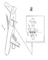
Figure 1 is a schematic view of an aircraft including an air management system. -
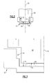
Figure 2 is a sectional view of an interface between an example valve shaft and an example thrust plate. -
Figure 3 is an enlarged view of the example thrust plate and thrust surface. -
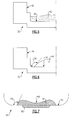
Figure 4 is schematic view of a disclosed process for forming a hardface on a thrust surface. -
Figure 5 is an enlarged cross-section of the example hardface alloy powder deposited on the example thrust surface. -
Figure 6 is a schematic view of a thrust surface geometry and solidified hardface alloy. -
Figure 7 is a schematic view of another thrust surface geometry and solidified hardface alloy. - Referring to
Figure 1 , anaircraft 10 includes anair management system 12 mounted to a support 14 within theaircraft 10. The exampleair management system 12 includes aconduit 16 that defines apassage 18 for air flow. Avalve assembly 20 controls airflow through thepassage 18 and includes avalve plate 22 mounted on ashaft 28 and rotated by anactuator 24 about anaxis 26. Theshaft 28 includes anaxial end 30 that is supported by athrust plate 32. Theexample thrust plate 32 limits movement of the shaft along theaxis 26. The exampleair management system 12 is required to operate within an extreme temperature range, at high vibration levels with little or no lubrication. Accordingly, theexample thrust plate 32 includes a hardface surface between abutting relative moving parts such as the interface between theaxial end 30 and thethrust plate 32. - Referring to
Figures 2 and 3 , theexample thrust plate 32 includes ahardface coating 38 disposed on athrust surface 34. Theexample thrust surface 34 is surrounded bywalls 36 that correspond with a profile of theshaft 28. Theaxial end 30 of theshaft 28 abuts and rotates on thehardface coating 38 to provide the desired wear protection. - The
example hardface coating 38 is formed from a hard and wear resistant material such as a Colmonoy 6 alloy (Ni-Cr-B-Si-Fe) with a Rockwell hardness (C scale) in a range between HRC 55 andHRC 60. Moreover other alloy compounds and materials that provide the desired wear performance at the extreme temperatures could also be utilized and are within the contemplation of this disclosure. Theexample thrust plate 32 is formed from a metal material compatible with the environment in which thevalve assembly 20 operates. The example metal material forming thethrust plate 32 is of hardness less than that of thehardface coating 38. - The
shaft 28 is engaged in abutting contact with thethrust surface 34 and therefore theentire thrust plate 32 does not encounter the wear experienced and is not required to be fabricated from a material capable of the wear resistance provided by thehardface coating 38. Thehardface coating 38 is therefore formed locally on the wear prone surfaces of thethrust plate 32. In this example, thethrust surface 34 receives the majority of contact and therefore is provided with thehardface coating 38. Other applications where wear resistance is desired could utilize a hardface alloy coating on other portions of the part and are within the contemplation of this disclosure. - The
example thrust plate 32 includes theside walls 36 surrounding therecessed thrust surface 34. Access to thethrust surface 34 is therefore complicated due to the confined area in which thehardface coating 38 is required. - Referring to
Figure 4 , an example process for locally applying thehardface coating 38 is schematically shown at 40 and includes an initial step of depositing ahardface alloy powder 42 onto the wear surface. In this example, thehardface alloy powder 42 is deposited on thethrust surface 34 that is recessed between thewalls 36. Thehardface alloy powder 42 settles on thethrust surface 34 and is distributed substantially evenly across thethrust surface 34. Thehardface alloy powder 42 is then leveled out as shown inFigure 5 and prepared for heating. - The
thrust plate 32 with thehardface alloy powder 42 is placed on a level even surface within avacuum furnace 44. The temperature within thevacuum furnace 44 is then raised to a first temperature that is below the melting point of thehardface alloy powder 42. Once a suitable vacuum pressure is attained, the vacuum furnace may be backfilled with a low partial pressure of an inert gas. This may be necessary for certain hardfacing alloys containing elements which are prone to out-gassing. The first temperature is maintained for a desired first dwell time such that thehardface alloy powder 42 may attain thermal equilibrium. As should be understood, the specific temperature and dwell time is dependent on the specific hardface alloy powder material along with the material comprising thethrust plate 32. - Once the
hardface alloy powder 42 has attained the desired thermal equilibrium, the temperature is raised to a second temperature above the liquidus temperature of thehardface alloy powder 42, but below a melting temperature of thethrust plate 32. Therefore, thehardface alloy powder 42 is heated to a molten liquid state indicated at 46 while thethrust plate 32 remains in the solid state. Accordingly, thehardface alloy powder 42 is formed from a material having a melting temperature lower than that of the material utilized to form thethrust plate 32. - Referring to
Figure 6 with continued reference toFigure 4 , transformation of thehardface alloy powder 42 into the moltenliquid hardface alloy 46 may generate surface tension. It is this surface tension that results in a slight contraction or balling up of the moltenliquid hardface alloy 46 as is schematically shown. The edges of the moltenliquid hardface alloy 46 draw inwardly away from theside walls 36 to form the doomed shape schematically shown. In this example, edges of the moltenliquid hardface alloy 46 draw away from theside walls 36 and form anangle 56 relative to thewear thrust surface 34. In this example, the angle is approximately 110°. It should be understood that other angles may result from different material and process parameters. - The second temperature is held for a second dwell time to provide substantially complete transformation of the
hardface alloy powder 42 into moltenliquid hardface alloy 46. Upon completion of the desired second dwell period at the second temperature, thethrust plate 32 is cooled to room temperature by inert gas quenching directly from the second temperature or controlled furnace cooling to a third cooling temperature below the solidus of the hardface alloy, then gas quenching. The second temperature may also include a temperature range below the liquidus temperature but above the solidus temperature where incipient melting is present such that most of thehardface alloy powder 42 is changed to the liquid state. Accordingly, it is within the contemplation of the disclosed process to utilize temperatures to change thehardface alloy powder 42 into a molten material, but is not required to be at the full liquidus temperature. - The cooling step is performed as a quench or slow cool from the second melting temperature to the third cooling temperature to solidify or freeze the molten
liquid hardface alloy 46 in the shape attained in the melting step. The frozen or solidified material substantially retains the shape attained at the second temperature. In the disclosed example, a dome shape is attained, however other shapes can be attained by leveling or otherwise orientating thehardface alloy powder 42. The resulting frozen orsolid hardface alloy 48 forms a predictable and repeatable shape that covers the desired portions of thethrust surface 34. The example thrustplate 32 is maintained at the third cooling temperature until a thermal equilibrium at room temperature is attained. The cooling process produces a dense coating of thesolid hardface alloy 48 with less than 1% porosity and uniform microstructure. - Once the
thrust plate 32 andsolid hardface alloy 48 is completely cooled, a machining step is performed to attain a desiredthickness 54 of the completedhardface coating 38. Amachine tool 52 is utilized to extend into the recess of thethrust plate 32 and machine thesolid hardface alloy 48 to the desiredthickness 54. The machine process utilized to attain the desired thickness may include any known material removal process compatible with the hardface alloy material and desired production parameters. The resultinghardface alloy coating 38 provides the desired wear resistant surface of thethrust plate 32. A subsequent heat treat may be implemented to restore thrustplate 32 mechanical properties, since the braze process may anneal or solutionize the chosen base metal. - Referring to
Figure 7 , anotherexample thrust plate 60 includes arecess 62 disposed belowthrust surface 70 that receives a portion of the hardface alloy 64. A portion of the hardface alloy 64 accumulates within therecess 62 and results in a correspondingdepression 66 on a top surface of the hardface alloy 64. The edges shown in this disclosed example of the solidified hardfaced alloy 64 forms theangle 68 during the melting process. The disclosed example angle and shape of the solidified hardfaced alloy 64 can be modified to provide other shapes as desired. Thedepression 66 is subsequently machined away to provide the desired smooth level wear surface. In this example, the hardface alloy 64 is machined away to thethrust surface 70. In other words, the resultingthrust surface 70 is flat and includes a desired thickness of the hardface alloy 64 that is disposed within therecess 62. This configuration provides a desired thickness of the hardface alloy 64 that is substantially flush with thethrust surface 70. - The hardface alloy powder can be deposited on discreet surfaces and locations to provide a desired wear surface in hard to reach locations. Moreover, different configurations can be utilized within the scope of the present invention to provide the desired hardface wear surface.
- Accordingly, the disclosed method of hard coating a wear surface of a valve of an aircraft air management system provides localized application and subsequent bonding of the hardface alloy to discrete portions of a thrust plate or other part. The solidified hardface alloy coating may then be machined to obtain specific wear surface geometries.
- Although an example embodiment has been disclosed, a worker of ordinary skill in this art would recognize that certain modifications would come within the scope of the invention, which is defined by the claims. For that reason, the following claims should be studied to determine the scope of this invention.
Claims (3)
- An air management system (12) for an aircraft (10) comprising:a valve plate (22) movable for controlling airflow through a passage (18);a valve shaft (28) including an axial end (30) supporting the valve plate within the passage; anda thrust plate (32) for controlling axial movement of the valve shaft, the thrust plate including a thrust surface (34;70) in contact with the axial end of the valve shaft, the thrust surface including a hardface alloy coating (38) formed from a hardface alloy powder (42) melted and solidified on the thrust surface, wherein the thrust surface is recessed and at least partially surrounded by walls.
- The air management system as recited in claim 1, wherein the valve shaft includes a first diameter received within the thrust plate that is less than a second diameter outside of the thrust plate.
- The air management system as recited in claim 1 or 2, wherein the solidified hardface alloy is machined to provide a desired thickness (54) on the thrust surface.
Priority Applications (1)
| Application Number | Priority Date | Filing Date | Title |
|---|---|---|---|
| EP14198391.6A EP2851449B1 (en) | 2010-11-05 | 2011-10-27 | Furnace braze deposition of hardface coating on wear surface |
Applications Claiming Priority (1)
| Application Number | Priority Date | Filing Date | Title |
|---|---|---|---|
| US12/940,558 US9976664B2 (en) | 2010-11-05 | 2010-11-05 | Furnace braze deposition of hardface coating on wear surface |
Related Child Applications (2)
| Application Number | Title | Priority Date | Filing Date |
|---|---|---|---|
| EP14198391.6A Division EP2851449B1 (en) | 2010-11-05 | 2011-10-27 | Furnace braze deposition of hardface coating on wear surface |
| EP14198391.6A Division-Into EP2851449B1 (en) | 2010-11-05 | 2011-10-27 | Furnace braze deposition of hardface coating on wear surface |
Publications (2)
| Publication Number | Publication Date |
|---|---|
| EP2450472A1 EP2450472A1 (en) | 2012-05-09 |
| EP2450472B1 true EP2450472B1 (en) | 2015-03-04 |
Family
ID=45062880
Family Applications (2)
| Application Number | Title | Priority Date | Filing Date |
|---|---|---|---|
| EP11187001.0A Active EP2450472B1 (en) | 2010-11-05 | 2011-10-27 | Air management system for an aircraft with hardface coating on wear surface of a valve |
| EP14198391.6A Active EP2851449B1 (en) | 2010-11-05 | 2011-10-27 | Furnace braze deposition of hardface coating on wear surface |
Family Applications After (1)
| Application Number | Title | Priority Date | Filing Date |
|---|---|---|---|
| EP14198391.6A Active EP2851449B1 (en) | 2010-11-05 | 2011-10-27 | Furnace braze deposition of hardface coating on wear surface |
Country Status (2)
| Country | Link |
|---|---|
| US (2) | US9976664B2 (en) |
| EP (2) | EP2450472B1 (en) |
Families Citing this family (1)
| Publication number | Priority date | Publication date | Assignee | Title |
|---|---|---|---|---|
| CN106151568A (en) * | 2016-08-22 | 2016-11-23 | 雷蒙德(北京)科技股份有限公司 | Cock processing technique, cock and plug valve |
Citations (6)
| Publication number | Priority date | Publication date | Assignee | Title |
|---|---|---|---|---|
| US2934312A (en) * | 1957-10-29 | 1960-04-26 | Garrett Corp | Thrust compensating device for axially inclined butterfly valves |
| JPS5786537A (en) * | 1980-11-17 | 1982-05-29 | Hitachi Ltd | Operation regulator for throttle valve shaft |
| US5716143A (en) * | 1995-07-12 | 1998-02-10 | Allegheny Ludlum Corporation | Spherical plain bearing |
| WO1998008639A1 (en) * | 1996-08-28 | 1998-03-05 | Deere & Company | Method for hardfacing a metal surface |
| CN2391064Y (en) * | 1999-09-15 | 2000-08-09 | 上海石油化工股份有限公司 | External butterfly non-return valve of axial displacement limiting mechanism |
| US20090080817A1 (en) * | 2007-09-26 | 2009-03-26 | Nidec Corporation | Fluid dynamic pressure bearing, spindle motor, disk driver, and production method of the fluid dynamic pressure bearing |
Family Cites Families (47)
| Publication number | Priority date | Publication date | Assignee | Title |
|---|---|---|---|---|
| US2361962A (en) | 1942-06-11 | 1944-11-07 | Ronay Bela | Method of metal-clading |
| US2672806A (en) * | 1950-06-05 | 1954-03-23 | North American Aviation Inc | Regulator valve |
| US3143132A (en) * | 1961-06-12 | 1964-08-04 | Fisher Governor Co | Seal arrangement for a butterfly valve |
| US4139660A (en) * | 1963-07-16 | 1979-02-13 | Bernhard Joos | Method for increasing solid surface tension |
| US3570142A (en) * | 1968-12-23 | 1971-03-16 | Jerry N Koral | Scientific educational device for teaching wettability and suspendibility |
| US3642519A (en) | 1969-03-21 | 1972-02-15 | Us Air Force | Method for the development of hard coat seal surfaces |
| US4024617A (en) * | 1973-03-06 | 1977-05-24 | Ramsey Corporation | Method of applying a refractory coating to metal substrate |
| US4237362A (en) | 1978-09-28 | 1980-12-02 | Tapco International, Inc. | Method of producing hardfaced plate |
| US4529169A (en) * | 1983-01-07 | 1985-07-16 | Cummins Engine Company, Inc. | Hardfaced valves and method of making same |
| US4837417A (en) | 1983-12-05 | 1989-06-06 | Funk Charles F | Method of hard-facing a metal surface |
| US4615903A (en) * | 1985-07-01 | 1986-10-07 | The United States Of America As Represented By The Secretary Of The Navy | Method for melt-coating a surface |
| US5051112A (en) | 1988-06-29 | 1991-09-24 | Smith International, Inc. | Hard facing |
| US4942059A (en) * | 1988-09-29 | 1990-07-17 | Westinghouse Electric Corp. | Method for hardfacing metal articles |
| US5271965A (en) * | 1991-01-16 | 1993-12-21 | Browning James A | Thermal spray method utilizing in-transit powder particle temperatures below their melting point |
| DE4234740C2 (en) * | 1992-10-15 | 1997-12-11 | Joachim Hentze | Process for the production of optical elements |
| JPH0778242B2 (en) * | 1993-02-12 | 1995-08-23 | 日本ユテク株式会社 | Method for manufacturing wear resistant composite metal member |
| US5749218A (en) | 1993-12-17 | 1998-05-12 | General Electric Co. | Wear reduction kit for gas turbine combustors |
| US6186508B1 (en) | 1996-11-27 | 2001-02-13 | United Technologies Corporation | Wear resistant coating for brush seal applications |
| JP3173452B2 (en) | 1997-02-28 | 2001-06-04 | 株式会社豊田中央研究所 | Wear-resistant covering member and method of manufacturing the same |
| US6048171A (en) * | 1997-09-09 | 2000-04-11 | United Technologies Corporation | Bleed valve system |
| US6082291A (en) | 1997-12-19 | 2000-07-04 | United Technologies Corporation | Fixture for use in disposing a region of material on the shroud of a rotor blade |
| US6034344A (en) | 1997-12-19 | 2000-03-07 | United Technologies Corp. | Method for applying material to a face of a flow directing assembly for a gas turbine engine |
| US6156391A (en) | 1999-06-14 | 2000-12-05 | Rankin Industries, Inc. | Process for hard facing a metallic substrate to improve wear resistance |
| WO2003066265A2 (en) * | 2002-02-05 | 2003-08-14 | Ipsen International, Inc. | Vacuum compression brazing furnace and method of using same |
| US6888088B2 (en) | 2002-11-01 | 2005-05-03 | Jimmie Brooks Bolton | Hardfacing materials & methods |
| US20040157066A1 (en) * | 2003-02-07 | 2004-08-12 | Arzoumanidis G. Alexis | Method of applying a hardcoating typically provided on downhole tools, and a system and apparatus having such a hardcoating |
| US7361411B2 (en) | 2003-04-21 | 2008-04-22 | Att Technology, Ltd. | Hardfacing alloy, methods, and products |
| US20050064095A1 (en) * | 2003-09-19 | 2005-03-24 | Deere & Company, A Delaware Corporation | Method for applying wear and corrosion resistant coating to cast iron |
| JP2005248987A (en) * | 2004-03-01 | 2005-09-15 | Denso Corp | Bearing support device |
| DE102004034410A1 (en) * | 2004-07-16 | 2006-02-02 | Mtu Aero Engines Gmbh | Protective layer for application to a substrate and method for producing a protective layer |
| US7479299B2 (en) * | 2005-01-26 | 2009-01-20 | Honeywell International Inc. | Methods of forming high strength coatings |
| US7325569B2 (en) * | 2005-04-25 | 2008-02-05 | Honeywell International, Inc. | Butterfly valve with integral split flapper relief valve |
| US20060272909A1 (en) * | 2005-06-02 | 2006-12-07 | Fuller Brian K | Brake assembly and coating |
| US20070141375A1 (en) | 2005-12-20 | 2007-06-21 | Budinger David E | Braze cladding for direct metal laser sintered materials |
| US8703044B2 (en) * | 2006-01-03 | 2014-04-22 | General Electric Company | Machine components and methods of fabricating and repairing |
| US7535150B1 (en) | 2006-05-08 | 2009-05-19 | Prc Laser Corporation | Centrifugal turbine blower with gas foil bearings |
| GB0616116D0 (en) * | 2006-08-12 | 2006-09-20 | Rolls Royce Plc | A method of forming a component on a substrate |
| GB2449862B (en) * | 2007-06-05 | 2009-09-16 | Rolls Royce Plc | Method for producing abrasive tips for gas turbine blades |
| US20090041611A1 (en) * | 2007-08-07 | 2009-02-12 | General Electric Company | Braze alloy composition with enhanced oxidation resistance and methods of using the same |
| JP4591722B2 (en) * | 2008-01-24 | 2010-12-01 | 信越化学工業株式会社 | Manufacturing method of ceramic sprayed member |
| JP5815947B2 (en) * | 2008-02-07 | 2015-11-17 | ブルースコープ・スティール・リミテッドBluescope Steel Limited | How to produce a coating on a steel strip |
| US8869988B2 (en) * | 2008-05-08 | 2014-10-28 | M-I L.L.C. | Cooling and classifying apparatus for pelletized product processing |
| US20100206527A1 (en) * | 2009-02-18 | 2010-08-19 | Hu Lin-Wen | In-Situ Treatment of Metallic Surfaces |
| CA2760455A1 (en) * | 2009-04-30 | 2010-11-04 | Chevron U.S.A. Inc. | Surface treatment of amorphous coatings |
| US8647449B2 (en) * | 2009-09-17 | 2014-02-11 | Scoperta, Inc. | Alloys for hardbanding weld overlays |
| US8562760B2 (en) * | 2009-09-17 | 2013-10-22 | Scoperta, Inc. | Compositions and methods for determining alloys for thermal spray, weld overlay, thermal spray post processing applications, and castings |
| US8662099B2 (en) * | 2010-04-23 | 2014-03-04 | Fisher Controls International, Llc | Valve shaft apparatus for use with rotary valves |
-
2010
- 2010-11-05 US US12/940,558 patent/US9976664B2/en active Active
-
2011
- 2011-10-27 EP EP11187001.0A patent/EP2450472B1/en active Active
- 2011-10-27 EP EP14198391.6A patent/EP2851449B1/en active Active
-
2016
- 2016-06-17 US US15/185,188 patent/US10495231B2/en active Active
Patent Citations (6)
| Publication number | Priority date | Publication date | Assignee | Title |
|---|---|---|---|---|
| US2934312A (en) * | 1957-10-29 | 1960-04-26 | Garrett Corp | Thrust compensating device for axially inclined butterfly valves |
| JPS5786537A (en) * | 1980-11-17 | 1982-05-29 | Hitachi Ltd | Operation regulator for throttle valve shaft |
| US5716143A (en) * | 1995-07-12 | 1998-02-10 | Allegheny Ludlum Corporation | Spherical plain bearing |
| WO1998008639A1 (en) * | 1996-08-28 | 1998-03-05 | Deere & Company | Method for hardfacing a metal surface |
| CN2391064Y (en) * | 1999-09-15 | 2000-08-09 | 上海石油化工股份有限公司 | External butterfly non-return valve of axial displacement limiting mechanism |
| US20090080817A1 (en) * | 2007-09-26 | 2009-03-26 | Nidec Corporation | Fluid dynamic pressure bearing, spindle motor, disk driver, and production method of the fluid dynamic pressure bearing |
Also Published As
| Publication number | Publication date |
|---|---|
| US10495231B2 (en) | 2019-12-03 |
| EP2450472A1 (en) | 2012-05-09 |
| EP2851449B1 (en) | 2019-03-27 |
| US20120115407A1 (en) | 2012-05-10 |
| EP2851449A2 (en) | 2015-03-25 |
| EP2851449A3 (en) | 2015-08-12 |
| US9976664B2 (en) | 2018-05-22 |
| US20160298780A1 (en) | 2016-10-13 |
Similar Documents
| Publication | Publication Date | Title |
|---|---|---|
| EP3010671B1 (en) | Method for producing a three-dimensional article | |
| JP5757720B2 (en) | Abrasive single crystal turbine blade | |
| EP2090396B1 (en) | System an process for solid state depositing of metals | |
| EP3029113B1 (en) | Abrasive coated substrate and method for manufacturing thereof | |
| US5359770A (en) | Method for bonding abrasive blade tips to the tip of a gas turbine blade | |
| EP1803521B1 (en) | Machine components and methods of fabricating and repairing | |
| EP2751304B1 (en) | Manufacturing a component of single crystal or directionally solidified material | |
| EP3459673B1 (en) | Additive manufacturing in situ stress relief | |
| EP2158059B1 (en) | Welding enclosure, welding apparatus comprising such welding enclosure and a method of welding first and second weld elements using a weld enclosure | |
| RU2599925C2 (en) | Systems and methods for processing alloy ingots | |
| US10906100B2 (en) | Heat treatment process for additive manufactured components | |
| CN102575332A (en) | Low CTE slush molds with textured surface, and method of making and using the same | |
| US20150290707A1 (en) | Working additively manufactured parts | |
| WO2019014445A1 (en) | Method of repairing an article and associated article | |
| CA2030427A1 (en) | Method of enhancing bond joint structural integrity of spray cast articles | |
| US7425115B2 (en) | Thermal turbomachine | |
| EP2450127B1 (en) | High temperature die casting apparatus and method therefor | |
| US10495231B2 (en) | Furnace braze deposition of hardface coating on wear surface | |
| WO2017083273A1 (en) | Thermal coating for mechanical seals | |
| RU2619419C2 (en) | Application method of titanium aluminide and product with titanium aluminide surface | |
| US20160076128A1 (en) | Thermal Spray Coating for Mechanical Face Seals | |
| US20160146020A1 (en) | BRAZING METHOD FOR REINFORCING THE Z-NOTCH OF TiAl BLADES | |
| KR101962343B1 (en) | Cutting blade | |
| Mayer et al. | Analysis of Different High-Velocity Thermally Sprayed Coatings to Recover AISI H13 High-Pressure Die Casting Molds | |
| Das et al. | Direct Laser Fabrication of a Gas Turbine Engine Component-Microstructure and Properties-Part I |
Legal Events
| Date | Code | Title | Description |
|---|---|---|---|
| PUAI | Public reference made under article 153(3) epc to a published international application that has entered the european phase |
Free format text: ORIGINAL CODE: 0009012 |
|
| AK | Designated contracting states |
Kind code of ref document: A1 Designated state(s): AL AT BE BG CH CY CZ DE DK EE ES FI FR GB GR HR HU IE IS IT LI LT LU LV MC MK MT NL NO PL PT RO RS SE SI SK SM TR |
|
| AX | Request for extension of the european patent |
Extension state: BA ME |
|
| 17P | Request for examination filed |
Effective date: 20121109 |
|
| 17Q | First examination report despatched |
Effective date: 20130815 |
|
| GRAP | Despatch of communication of intention to grant a patent |
Free format text: ORIGINAL CODE: EPIDOSNIGR1 |
|
| INTG | Intention to grant announced |
Effective date: 20140923 |
|
| GRAS | Grant fee paid |
Free format text: ORIGINAL CODE: EPIDOSNIGR3 |
|
| GRAA | (expected) grant |
Free format text: ORIGINAL CODE: 0009210 |
|
| AK | Designated contracting states |
Kind code of ref document: B1 Designated state(s): AL AT BE BG CH CY CZ DE DK EE ES FI FR GB GR HR HU IE IS IT LI LT LU LV MC MK MT NL NO PL PT RO RS SE SI SK SM TR |
|
| REG | Reference to a national code |
Ref country code: GB Ref legal event code: FG4D |
|
| REG | Reference to a national code |
Ref country code: CH Ref legal event code: EP |
|
| REG | Reference to a national code |
Ref country code: IE Ref legal event code: FG4D |
|
| REG | Reference to a national code |
Ref country code: AT Ref legal event code: REF Ref document number: 713990 Country of ref document: AT Kind code of ref document: T Effective date: 20150415 |
|
| REG | Reference to a national code |
Ref country code: DE Ref legal event code: R096 Ref document number: 602011014282 Country of ref document: DE Effective date: 20150416 |
|
| REG | Reference to a national code |
Ref country code: AT Ref legal event code: MK05 Ref document number: 713990 Country of ref document: AT Kind code of ref document: T Effective date: 20150304 Ref country code: NL Ref legal event code: VDEP Effective date: 20150304 |
|
| PG25 | Lapsed in a contracting state [announced via postgrant information from national office to epo] |
Ref country code: SE Free format text: LAPSE BECAUSE OF FAILURE TO SUBMIT A TRANSLATION OF THE DESCRIPTION OR TO PAY THE FEE WITHIN THE PRESCRIBED TIME-LIMIT Effective date: 20150304 Ref country code: HR Free format text: LAPSE BECAUSE OF FAILURE TO SUBMIT A TRANSLATION OF THE DESCRIPTION OR TO PAY THE FEE WITHIN THE PRESCRIBED TIME-LIMIT Effective date: 20150304 Ref country code: ES Free format text: LAPSE BECAUSE OF FAILURE TO SUBMIT A TRANSLATION OF THE DESCRIPTION OR TO PAY THE FEE WITHIN THE PRESCRIBED TIME-LIMIT Effective date: 20150304 Ref country code: NO Free format text: LAPSE BECAUSE OF FAILURE TO SUBMIT A TRANSLATION OF THE DESCRIPTION OR TO PAY THE FEE WITHIN THE PRESCRIBED TIME-LIMIT Effective date: 20150604 Ref country code: FI Free format text: LAPSE BECAUSE OF FAILURE TO SUBMIT A TRANSLATION OF THE DESCRIPTION OR TO PAY THE FEE WITHIN THE PRESCRIBED TIME-LIMIT Effective date: 20150304 Ref country code: LT Free format text: LAPSE BECAUSE OF FAILURE TO SUBMIT A TRANSLATION OF THE DESCRIPTION OR TO PAY THE FEE WITHIN THE PRESCRIBED TIME-LIMIT Effective date: 20150304 |
|
| REG | Reference to a national code |
Ref country code: LT Ref legal event code: MG4D |
|
| PG25 | Lapsed in a contracting state [announced via postgrant information from national office to epo] |
Ref country code: LV Free format text: LAPSE BECAUSE OF FAILURE TO SUBMIT A TRANSLATION OF THE DESCRIPTION OR TO PAY THE FEE WITHIN THE PRESCRIBED TIME-LIMIT Effective date: 20150304 Ref country code: AT Free format text: LAPSE BECAUSE OF FAILURE TO SUBMIT A TRANSLATION OF THE DESCRIPTION OR TO PAY THE FEE WITHIN THE PRESCRIBED TIME-LIMIT Effective date: 20150304 Ref country code: RS Free format text: LAPSE BECAUSE OF FAILURE TO SUBMIT A TRANSLATION OF THE DESCRIPTION OR TO PAY THE FEE WITHIN THE PRESCRIBED TIME-LIMIT Effective date: 20150304 Ref country code: GR Free format text: LAPSE BECAUSE OF FAILURE TO SUBMIT A TRANSLATION OF THE DESCRIPTION OR TO PAY THE FEE WITHIN THE PRESCRIBED TIME-LIMIT Effective date: 20150605 |
|
| PG25 | Lapsed in a contracting state [announced via postgrant information from national office to epo] |
Ref country code: NL Free format text: LAPSE BECAUSE OF FAILURE TO SUBMIT A TRANSLATION OF THE DESCRIPTION OR TO PAY THE FEE WITHIN THE PRESCRIBED TIME-LIMIT Effective date: 20150304 |
|
| PG25 | Lapsed in a contracting state [announced via postgrant information from national office to epo] |
Ref country code: CZ Free format text: LAPSE BECAUSE OF FAILURE TO SUBMIT A TRANSLATION OF THE DESCRIPTION OR TO PAY THE FEE WITHIN THE PRESCRIBED TIME-LIMIT Effective date: 20150304 Ref country code: PT Free format text: LAPSE BECAUSE OF FAILURE TO SUBMIT A TRANSLATION OF THE DESCRIPTION OR TO PAY THE FEE WITHIN THE PRESCRIBED TIME-LIMIT Effective date: 20150706 Ref country code: EE Free format text: LAPSE BECAUSE OF FAILURE TO SUBMIT A TRANSLATION OF THE DESCRIPTION OR TO PAY THE FEE WITHIN THE PRESCRIBED TIME-LIMIT Effective date: 20150304 Ref country code: SK Free format text: LAPSE BECAUSE OF FAILURE TO SUBMIT A TRANSLATION OF THE DESCRIPTION OR TO PAY THE FEE WITHIN THE PRESCRIBED TIME-LIMIT Effective date: 20150304 Ref country code: RO Free format text: LAPSE BECAUSE OF FAILURE TO SUBMIT A TRANSLATION OF THE DESCRIPTION OR TO PAY THE FEE WITHIN THE PRESCRIBED TIME-LIMIT Effective date: 20150304 |
|
| PG25 | Lapsed in a contracting state [announced via postgrant information from national office to epo] |
Ref country code: PL Free format text: LAPSE BECAUSE OF FAILURE TO SUBMIT A TRANSLATION OF THE DESCRIPTION OR TO PAY THE FEE WITHIN THE PRESCRIBED TIME-LIMIT Effective date: 20150304 Ref country code: IS Free format text: LAPSE BECAUSE OF FAILURE TO SUBMIT A TRANSLATION OF THE DESCRIPTION OR TO PAY THE FEE WITHIN THE PRESCRIBED TIME-LIMIT Effective date: 20150704 |
|
| REG | Reference to a national code |
Ref country code: DE Ref legal event code: R097 Ref document number: 602011014282 Country of ref document: DE |
|
| PLBE | No opposition filed within time limit |
Free format text: ORIGINAL CODE: 0009261 |
|
| STAA | Information on the status of an ep patent application or granted ep patent |
Free format text: STATUS: NO OPPOSITION FILED WITHIN TIME LIMIT |
|
| PG25 | Lapsed in a contracting state [announced via postgrant information from national office to epo] |
Ref country code: DK Free format text: LAPSE BECAUSE OF FAILURE TO SUBMIT A TRANSLATION OF THE DESCRIPTION OR TO PAY THE FEE WITHIN THE PRESCRIBED TIME-LIMIT Effective date: 20150304 |
|
| 26N | No opposition filed |
Effective date: 20151207 |
|
| PG25 | Lapsed in a contracting state [announced via postgrant information from national office to epo] |
Ref country code: SI Free format text: LAPSE BECAUSE OF FAILURE TO SUBMIT A TRANSLATION OF THE DESCRIPTION OR TO PAY THE FEE WITHIN THE PRESCRIBED TIME-LIMIT Effective date: 20150304 |
|
| REG | Reference to a national code |
Ref country code: DE Ref legal event code: R119 Ref document number: 602011014282 Country of ref document: DE |
|
| PG25 | Lapsed in a contracting state [announced via postgrant information from national office to epo] |
Ref country code: LU Free format text: LAPSE BECAUSE OF FAILURE TO SUBMIT A TRANSLATION OF THE DESCRIPTION OR TO PAY THE FEE WITHIN THE PRESCRIBED TIME-LIMIT Effective date: 20151027 |
|
| REG | Reference to a national code |
Ref country code: CH Ref legal event code: PL |
|
| GBPC | Gb: european patent ceased through non-payment of renewal fee |
Effective date: 20151027 |
|
| PG25 | Lapsed in a contracting state [announced via postgrant information from national office to epo] |
Ref country code: MC Free format text: LAPSE BECAUSE OF FAILURE TO SUBMIT A TRANSLATION OF THE DESCRIPTION OR TO PAY THE FEE WITHIN THE PRESCRIBED TIME-LIMIT Effective date: 20150304 |
|
| REG | Reference to a national code |
Ref country code: IE Ref legal event code: MM4A |
|
| PG25 | Lapsed in a contracting state [announced via postgrant information from national office to epo] |
Ref country code: DE Free format text: LAPSE BECAUSE OF NON-PAYMENT OF DUE FEES Effective date: 20160503 Ref country code: LI Free format text: LAPSE BECAUSE OF NON-PAYMENT OF DUE FEES Effective date: 20151031 Ref country code: CH Free format text: LAPSE BECAUSE OF NON-PAYMENT OF DUE FEES Effective date: 20151031 Ref country code: GB Free format text: LAPSE BECAUSE OF NON-PAYMENT OF DUE FEES Effective date: 20151027 |
|
| PG25 | Lapsed in a contracting state [announced via postgrant information from national office to epo] |
Ref country code: BE Free format text: LAPSE BECAUSE OF FAILURE TO SUBMIT A TRANSLATION OF THE DESCRIPTION OR TO PAY THE FEE WITHIN THE PRESCRIBED TIME-LIMIT Effective date: 20150304 |
|
| REG | Reference to a national code |
Ref country code: FR Ref legal event code: PLFP Year of fee payment: 6 |
|
| PG25 | Lapsed in a contracting state [announced via postgrant information from national office to epo] |
Ref country code: IE Free format text: LAPSE BECAUSE OF NON-PAYMENT OF DUE FEES Effective date: 20151027 |
|
| PG25 | Lapsed in a contracting state [announced via postgrant information from national office to epo] |
Ref country code: SM Free format text: LAPSE BECAUSE OF FAILURE TO SUBMIT A TRANSLATION OF THE DESCRIPTION OR TO PAY THE FEE WITHIN THE PRESCRIBED TIME-LIMIT Effective date: 20150304 Ref country code: HU Free format text: LAPSE BECAUSE OF FAILURE TO SUBMIT A TRANSLATION OF THE DESCRIPTION OR TO PAY THE FEE WITHIN THE PRESCRIBED TIME-LIMIT; INVALID AB INITIO Effective date: 20111027 Ref country code: BG Free format text: LAPSE BECAUSE OF FAILURE TO SUBMIT A TRANSLATION OF THE DESCRIPTION OR TO PAY THE FEE WITHIN THE PRESCRIBED TIME-LIMIT Effective date: 20150304 |
|
| PG25 | Lapsed in a contracting state [announced via postgrant information from national office to epo] |
Ref country code: CY Free format text: LAPSE BECAUSE OF FAILURE TO SUBMIT A TRANSLATION OF THE DESCRIPTION OR TO PAY THE FEE WITHIN THE PRESCRIBED TIME-LIMIT Effective date: 20150304 |
|
| PG25 | Lapsed in a contracting state [announced via postgrant information from national office to epo] |
Ref country code: TR Free format text: LAPSE BECAUSE OF FAILURE TO SUBMIT A TRANSLATION OF THE DESCRIPTION OR TO PAY THE FEE WITHIN THE PRESCRIBED TIME-LIMIT Effective date: 20150304 Ref country code: MT Free format text: LAPSE BECAUSE OF FAILURE TO SUBMIT A TRANSLATION OF THE DESCRIPTION OR TO PAY THE FEE WITHIN THE PRESCRIBED TIME-LIMIT Effective date: 20150304 |
|
| REG | Reference to a national code |
Ref country code: FR Ref legal event code: PLFP Year of fee payment: 7 |
|
| PG25 | Lapsed in a contracting state [announced via postgrant information from national office to epo] |
Ref country code: MK Free format text: LAPSE BECAUSE OF FAILURE TO SUBMIT A TRANSLATION OF THE DESCRIPTION OR TO PAY THE FEE WITHIN THE PRESCRIBED TIME-LIMIT Effective date: 20150304 |
|
| REG | Reference to a national code |
Ref country code: FR Ref legal event code: PLFP Year of fee payment: 8 |
|
| PG25 | Lapsed in a contracting state [announced via postgrant information from national office to epo] |
Ref country code: AL Free format text: LAPSE BECAUSE OF FAILURE TO SUBMIT A TRANSLATION OF THE DESCRIPTION OR TO PAY THE FEE WITHIN THE PRESCRIBED TIME-LIMIT Effective date: 20150304 |
|
| P01 | Opt-out of the competence of the unified patent court (upc) registered |
Effective date: 20230522 |
|
| PGFP | Annual fee paid to national office [announced via postgrant information from national office to epo] |
Ref country code: IT Payment date: 20250923 Year of fee payment: 15 |
|
| PGFP | Annual fee paid to national office [announced via postgrant information from national office to epo] |
Ref country code: FR Payment date: 20250924 Year of fee payment: 15 |