EP2450212A2 - Roof apparatus for vehicle - Google Patents
Roof apparatus for vehicle Download PDFInfo
- Publication number
- EP2450212A2 EP2450212A2 EP11177047A EP11177047A EP2450212A2 EP 2450212 A2 EP2450212 A2 EP 2450212A2 EP 11177047 A EP11177047 A EP 11177047A EP 11177047 A EP11177047 A EP 11177047A EP 2450212 A2 EP2450212 A2 EP 2450212A2
- Authority
- EP
- European Patent Office
- Prior art keywords
- vehicle
- tooth rack
- rack belt
- spur
- portions
- Prior art date
- Legal status (The legal status is an assumption and is not a legal conclusion. Google has not performed a legal analysis and makes no representation as to the accuracy of the status listed.)
- Granted
Links
- 238000005192 partition Methods 0.000 claims description 18
- 239000000463 material Substances 0.000 description 8
- 229920003002 synthetic resin Polymers 0.000 description 6
- 239000000057 synthetic resin Substances 0.000 description 6
- 238000000465 moulding Methods 0.000 description 4
- 230000002441 reversible effect Effects 0.000 description 3
- 230000002159 abnormal effect Effects 0.000 description 2
- 238000004891 communication Methods 0.000 description 2
- 238000000034 method Methods 0.000 description 2
- XLYOFNOQVPJJNP-UHFFFAOYSA-N water Substances O XLYOFNOQVPJJNP-UHFFFAOYSA-N 0.000 description 2
- 229910000838 Al alloy Inorganic materials 0.000 description 1
- 230000000694 effects Effects 0.000 description 1
- 229910052751 metal Inorganic materials 0.000 description 1
- 239000002184 metal Substances 0.000 description 1
- 239000007769 metal material Substances 0.000 description 1
Images


Classifications
-
- B—PERFORMING OPERATIONS; TRANSPORTING
- B60—VEHICLES IN GENERAL
- B60J—WINDOWS, WINDSCREENS, NON-FIXED ROOFS, DOORS, OR SIMILAR DEVICES FOR VEHICLES; REMOVABLE EXTERNAL PROTECTIVE COVERINGS SPECIALLY ADAPTED FOR VEHICLES
- B60J7/00—Non-fixed roofs; Roofs with movable panels, e.g. rotary sunroofs
- B60J7/02—Non-fixed roofs; Roofs with movable panels, e.g. rotary sunroofs of sliding type, e.g. comprising guide shoes
- B60J7/04—Non-fixed roofs; Roofs with movable panels, e.g. rotary sunroofs of sliding type, e.g. comprising guide shoes with rigid plate-like element or elements, e.g. open roofs with harmonica-type folding rigid panels
- B60J7/057—Driving or actuating arrangements e.g. manually operated levers or knobs
- B60J7/0573—Driving or actuating arrangements e.g. manually operated levers or knobs power driven arrangements, e.g. electrical
-
- B—PERFORMING OPERATIONS; TRANSPORTING
- B60—VEHICLES IN GENERAL
- B60J—WINDOWS, WINDSCREENS, NON-FIXED ROOFS, DOORS, OR SIMILAR DEVICES FOR VEHICLES; REMOVABLE EXTERNAL PROTECTIVE COVERINGS SPECIALLY ADAPTED FOR VEHICLES
- B60J7/00—Non-fixed roofs; Roofs with movable panels, e.g. rotary sunroofs
- B60J7/02—Non-fixed roofs; Roofs with movable panels, e.g. rotary sunroofs of sliding type, e.g. comprising guide shoes
- B60J7/022—Sliding roof trays or assemblies
-
- B—PERFORMING OPERATIONS; TRANSPORTING
- B60—VEHICLES IN GENERAL
- B60J—WINDOWS, WINDSCREENS, NON-FIXED ROOFS, DOORS, OR SIMILAR DEVICES FOR VEHICLES; REMOVABLE EXTERNAL PROTECTIVE COVERINGS SPECIALLY ADAPTED FOR VEHICLES
- B60J7/00—Non-fixed roofs; Roofs with movable panels, e.g. rotary sunroofs
- B60J7/02—Non-fixed roofs; Roofs with movable panels, e.g. rotary sunroofs of sliding type, e.g. comprising guide shoes
- B60J7/04—Non-fixed roofs; Roofs with movable panels, e.g. rotary sunroofs of sliding type, e.g. comprising guide shoes with rigid plate-like element or elements, e.g. open roofs with harmonica-type folding rigid panels
Definitions
- This disclosure generally relates to a roof apparatus for a vehicle.
- a known roof apparatus for a vehicle includes a pair of left side and right side guide rails, a movable panel, a housing and a pair of drive force transmitting members.
- the pair of guide rails extends along a front/rear direction of a vehicle along both side portions of an opening portion formed on a roof of the vehicle.
- the movable panel for opening and closing the opening portion is supported by the pair of guide rails so as to be slidable in the front/rear direction of the vehicle.
- the housing extends in the width direction of the vehicle along a front portion of the opening portion and is connected to a front end surface of each of the pair of guide rails.
- a drive mechanism and a casing are provided at the housing.
- the drive force transmitting member is inserted into the casing.
- the drive force transmitting member is guided by and slides along the casing and the pair of guide rails, and thus moves the sliding panel in the front/rear direction of the vehicle for opening and closing the opening.
- a sunroof device for use in a vehicle in which drive cables are used as the drive force transmitting member is disclosed in JPH7-149153A (hereinafter referred to as Patent reference 1).
- the sunroof device for use of the vehicle according to the Patent reference 1 is constituted by the housing, and a guide plate which is fixedly attached to a lower face of the housing and into which the drive cables are inserted.
- spur tooth rack belts are used instead of the above-stated drive cables as the drive force transmitting member.
- Each of the spur tooth rack belts includes spur teeth protruding in a direction perpendicular to a longitudinal direction of the spur tooth rack belt in a manner that the surfaces, on which the spur teeth are formed, of the spur tooth rack belts face each other.
- a front end surface of each of the guide rails, against which the casing is abutted in order to connect the casing to each of the guide rails, is formed so as to be perpendicular to passages formed at the guide rails for having the driving cables inserted therein.
- the front end surface of each of the guide rails, to which the casing is connected is formed so as to be perpendicular to the passages of the spur tooth rack belts, the front end surface is positioned parallel to each of the spur teeth of the spur tooth rack belts, that is, parallel to the direction in which each of the spur teeth protrudes.
- each of the spur teeth may come into contact with more than one edge portions of the front end surface of each of the guide rails at a time when passing through the connecting portion between the casing and each of the guide rails in order to move from the casing to the guide rails. This may cause a noise (the tooth contact noise).
- a roof apparatus for a vehicle includes a pair of guide rails extending in a front/rear direction of the vehicle along side end portions of an opening portion formed on a roof of a vehicle, a movable panel supported by the pair of guide rails and opening and closing the opening portion by moving in the front/rear direction of the vehicle, a housing extending in a width direction of the vehicle along a front end portion of the opening portion, being connected to a front end portion of each of the pair of guide rails and supporting a drive mechanism, a casing at least part of which is constituted by the housing, a first spur tooth rack belt and a second spur tooth rack belt both of which are accommodated in the pair of guide rails and in the casing in a manner that the first spur tooth rack belt and the second spur tooth rack belt slide along the pair of guide rails and along the casing for transmitting a drive force of the drive mechanism to the movable panel.
- the first spur tooth rack belt includes a plurality of first spur teeth formed on a surface of the first spur tooth rack belt which faces a surface of the second spur tooth rack belt on which a plurality of second spur teeth are formed in a manner that the plurality of first spur teeth and the plurality of second spur teeth protrude in a direction perpendicular to a lengthwise direction of the first spur tooth rack belt and the second spur tooth rack belt, a slope portion constituting part of the casing and being inclined upward toward a rear side of the vehicle is provided forward of each of the pair of guide rails relative to the front/rear direction of the vehicle, a pair of guide portions is provided at each of the guide rails, the guide portions positioned keeping a distance from each other in the width direction of the vehicle for guiding the first spur tooth rack belt and the second spur tooth rack belt respectively in the front/rear direction of the vehicle, each of the pair of guide portions includes a bottom wall portion and a pair of restricting wall positioned at side portions of the bottom wall portion relative to the width direction of the vehicle, and
- the first and second spur teeth of the first and second spur tooth rack belts move from the slope portions to the left and the right guide rails
- the first and second spur teeth are guided by the slope portion to move gradually diagonally upward from a position, which is in the casing and which is lower than the left side and the right side guide rails in the vertical direction of the vehicle.
- the first and second spur teeth are inclined or tilted in a manner that upper portions of the first and second spur teeth are positioned forward and lower portions thereof are positioned rearward in the front/rear direction of the vehicle.
- the first and second spur teeth enter an inside of the guide rails portions via the cutout portions formed at the front end portions of the guide rails while maintaining the inclined or tilted state.
- the first and second spur teeth come into contact with the restricting wall portions of the guide portion of the guide rails in the tilted state, and thus a generation of a tooth contact noise is controlled.
- the roof apparatus for the vehicle which controls the tooth contact noise generated when the plurality of first and second spur teeth of the first and second spur tooth rack belts pass through a connecting portion between the casing and each of the pair of guide rails.
- each of the pair of guide rails includes a connecting bottom wall portion provided between the pair of guide portions for connecting the bottom wall portions with each other and the front end portion of each of the pair of guide rails includes an intermediate cutout portion formed by cutting out the connecting bottom wall portion.
- the connecting bottom wall portion is not directly involved in movements of the first spur tooth rack belt and the second spur tooth rack belt in the front/rear direction of the vehicle. Therefore, the intermediate cutout portion may be formed at the connecting bottom wall portion by cutting out, in the front/rear direction of the vehicle, a front end portion of the connecting bottom wall portion.
- an entire bottom portion of the front end portion of the each of the guide rails needs to be cut out. In this case, a process for forming the cutout portions is easier compared to the case where only the cutout portions are formed by cutting out the front end portions of the bottom wall portions. Further, a configuration of the slope portion of each of the casings may be simplified.
- the casing includes a casing body whose bottom portion downwardly opens and a casing cover closing the casing body from below, and passages into which the first spur tooth rack belt and the second spur tooth rack belt are inserted are formed between the casing body and the casing cover.
- the slope portion includes an upper portion and a lower portion, and the upper portion is constituted by part of the casing body and at least part of the lower portion is constituted by part of the casing cover.
- the casing is constituted by the casing body and the casing cover.
- the passages in which the first spur tooth rack belt and the second spur tooth rack belt are inserted, and the slope portion are formed in a simple way.
- the casing body includes a slope configuring portion provided forward of the bottom wall portions of the pair of guide portions relative to the front/rear direction of the vehicle and constituting part of the lower portion of the slope portion, and a recessed portion provided forward of the slope configuring portion in the front/rear direction of the vehicle, and a rear end portion of the casing cover engages with and is stopped by the recessed portion.
- the slope configuring portion which is positioned forward of the bottom wall portions of the guide portion relative to the front/rear direction of the vehicle, functions as part of the lower portion of the slope portion.
- the first and second spur teeth of the first and second spur tooth rack belts pass through the slope configuring portion in the tilted state when moving from the slope portion to the guide rails.
- Each of the casings is constituted by the casing and the casing cover, however, the casing cover is assembled to the casing body while being positioned relative to the casing body by having the locking protrusion engaged with and stopped by the recess.
- the slope configuring portion includes a pair of partition walls.
- the first spur tooth rack belt and the second spur tooth rack belt are restricted by the partition walls from moving in the width direction of the vehicle.
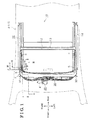
- Fig. 1 is a schematic plan view of a roof apparatus for a vehicle according to a first embodiment disclosed here;
- Fig. 2 is a cross-sectional view taken on line II-II of Fig. 1 ;
- Fig. 3 is a cross-sectional view taken on line III-III of Fig. 1 ;
- Fig. 4 is a cross-sectional view taken on line IV-IV of Fig. 1 ;
- Fig. 5 is a cross-sectional view taken on line V-V of Fig. 1 ;
- Fig. 6 is a cross-sectional view taken on line VI-VI of Fig. 1 ;
- Fig. 7 is a schematic partial view illustrating a right side portion of a front housing and a front end portion of a right side guide rail of the roof apparatus according to the first embodiment
- Fig. 8 is a schematic plane view illustrating an arrangement of a pair of outer spur tooth rack belt and an inner spur tooth rack belt in the front housing, in the right side guide rail and in a left side guide rail of the roof apparatus according to the first, second, third and fourth embodiments;
- Fig. 9 is a partial plan view illustrating the outer and inner spur tooth rack belts, and a spur gear engaging with the outer and inner spur tooth rack belts of the roof apparatus according to the first, second, third and fourth embodiments;
- Fig. 10 is a perspective view illustrating a positional relationship between a connecting portion at which a casing is connected to the right side guide rail, and the outer and inner spur tooth rack belts of the roof apparatus according to the first embodiment;
- Fig. 11 is a cross-sectional view taken on line XI-XI of Fig. 10 ;
- Fig. 12 is a schematic bottom view illustrating the roof apparatus for the vehicle according to the first, second, third and fourth embodiments in a state where the left side guide rail is not connected thereto;
- Fig. 13 is a partial perspective view illustrating a portion G of Fig. 12 when viewed from a direction of the arrow XIII of Fig. 12 ;
- Fig. 14 is a cross-sectional view corresponding to Fig. 4 , according to the second embodiment where an intermediate cutout portion is formed at a front end portion of a connecting bottom wall portion;
- Fig. 15 is a cross-sectional view corresponding to Fig. 4 , according to the third embodiment of this disclosure where a partition wall is formed on a casing cover;
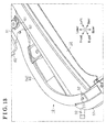
- Fig. 16 is a cross-sectional view corresponding to Fig. 4 , according to the fourth embodiment of this disclosure where a partition wall is formed on a guide rail.
- a front/rear direction refers to a forward/rearward direction relative to a traveling direction of the vehicle on which the roof apparatus 10 is mounted.
- An upper/lower direction or a vertical direction refers to an upper/lower direction or a vertical direction of the vehicle.
- a right/left direction or a width direction refers to a right/left direction or a width direction of the vehicle when the vehicle is traveling forward.
- the roof apparatus 10 for the vehicle opens and closes an opening portion 12 formed on a roof 11 of a vehicle 4 by means of a movable panel 13 in a similar manner used in a known sunroof apparatus.
- a pair of guide rails 14, 15, that is, a left side guide rail 14 and a right side guide rail 15, is provided below left side and right side edge portions of the opening portion 12 respectively so as to extend in the front/rear direction of the vehicle along the left side and the right side edge portions of the opening portion 12.
- a front housing 30 i.e., a housing
- the left side and the right side guide rails 14, 15 and the front housing 30 are fixedly attached to the roof 11.
- Each of the guide rails 14, 15 includes a uniform cross section that is perpendicular to a longitudinal direction thereof (the front/rear direction of the vehicle).
- the cross sections of the guide rails 14, 15 are symmetrical to each other in the width direction of the vehicle.
- the guide rails 14, 15 are formed from an extruded light metal material including aluminum alloy but not limited thereto.
- Link members 5, 6 each supporting the movable panel 13 from below are attached to the guide rails 14, 15 respectively so that the link members 5, 6 slide in the front/rear direction of the vehicle and are inclined or tiled upward toward a rear side of the vehicle.
- Shoe members 7, 8 for sliding the link members 5, 6 in the front/rear direction of the vehicle while inclining the link member 5, 6 upward toward the rear side of the vehicle are attached to the guide rails 14, 15 respectively in a manner that the shoe members 7, 8 slide along the guide rails 14, 15 in the front/rear direction of the vehicle.
- a left side guide portion 16 guiding an inner spur tooth rack belt 36 (i.e., a second spur tooth rack belt), which will be explained below, in the front/rear direction of the vehicle is provided at a left side portion of an inside of the right side guide rail 15.
- the left side guide portion 16 includes a bottom wall portion 17, a pair of restricting wall portions 18, 19 formed at left side and right side portions of the bottom wall portion 17 respectively in the width direction of the vehicle so as to upwardly protrude in the vertical direction of the vehicle, and an upper wall portion 21 formed on upper end portions of the restricting wall portions 18, 19 so as to protrude in the width direction of the vehicle and so as to connect the restricting wall portions 18, 19 with each other.
- a right side guide portion 22 guiding an outer spur tooth rack belt 35 (i.e., a first spur tooth rack belt), which will be explained below (refer to Figs. 4 and 5 ), in the front/rear direction of the vehicle is provided at a right side portion of the inside of the right side guide rail 15.
- the right side guide portion 22 includes a bottom wall portion 23, a pair of restricting wall portions 24, 25 formed at left side and right side portions of the bottom wall portion 23 in the width direction of the vehicle so as to upwardly protrude in the vertical direction of the vehicle, and an upper wall portion 26 formed on upper end portions of the restricting wall portions 24, 25 so as to protrude in the width direction of the vehicle and so as to connect the restricting wall portions 24, 25 with each other.
- a connecting bottom portion 27 is provided between the left side guide portions 16 and the right side guide portion 22 so as to connect the bottom wall portions 17 and 23.
- the connecting bottom portion 27, and the bottom portions 27 and 23 positioned at the left and right of the connecting bottom portion 27 respectively are coplanar to one another.
- the restricting wall portion 19 which is positioned closer to the connecting bottom wall portion 27 than the restricting wall portion 18 is positioned, is discontinued and separated in two at an intermediate portion thereof in the vertical direction of the vehicle.
- An upper portion and a lower portion of the restricting wall portion 19 will be identified as an upper restricting wall portion 19U and a lower restricting wall portion 19L respectively when necessary.
- the restricting wall portion 24 which is positioned closer to the connecting bottom wall portion 27 than the restricting wall portion 25 is positioned, is discontinued and separated in two at an intermediate portion thereof in the vertical direction of the vehicle.
- An upper portion and a lower portion of the restricting wall portion 24 will be identified as an upper restricting wall portion 24U and a lower restricting wall portion 24L respectively when necessary.
- the front housing 30 is formed by means of molding a synthetic resin material.
- the left and right end portions of the front housing 30 in the width direction of the vehicle are connected to front end portions of the guide rails 14, 15 respectively.
- a gutter portion 31 for receiving, for example, rain water entering an inside of the roof apparatus 10 through a front portion of the opening portion 12 is formed at an upper portion of the front housing 30 so as to be integral with the front housing 30 and to extend in the width direction of the vehicle.
- a drain pipe 32 is connected to each of the left and right portions of the gutter portion 31 in the width direction of the vehicle so that, for example, the rain water that drops into the gutter portion 31 is discharged outside the roof apparatus 10 through the drain pipes 32, 32.
- part of the front housing 30 constitutes part of each of a pair of casings 51, 52 provided on the left and right sides of the vehicle, which will be explained in details below.
- the outer spur tooth rack belt 35 and the inner spur tooth rack belt 36 are arranged substantially in parallel to each other in a longitudinal direction thereof in the casings 51, 52, the left side guide rail 14 and the right side guide rail 15.
- the outer spur tooth rack belt 35 extends in the width direction of the vehicle in the front housing 30 and extends in the front/rear direction of the vehicle in the guide rails 14, 15.
- the outer spur tooth rack belt 35 is arranged so as to curve at connecting portions between the left side and the right side portions of the front housing 30 (the casings 51, 52) and the guide rails 14, 15 respectively.
- the inner spur rack belt 36 is positioned rearward of the outer spur tooth rack belt 35 in the front/rear direction of the vehicle in the front housing 30, and is positioned inward of the outer spur tooth rack belt 35 in the width direction of the vehicle in the guide rails 14, 15, that is, closer to the lateral center of the vehicle. Due to the above-explained positional relationship, the outer spur tooth rack belt 35 and the inner spur tooth rack belt 36 do not intersect with each other at any point when viewed in a plane view. The outer spur tooth rack belt 35 and the inner spur tooth rack belt 36, however, may intersect with each other when viewed in the plane view.
- the outer spur tooth rack belt 35 includes plural spur teeth 35a (i.e., plural first spur teeth) formed on a surface facing the inner spur tooth rack belt 36 so that each of the spur teeth 35a protrudes in a direction perpendicular to the longitudinal direction of the outer spur tooth rack belt 35, that is, in the vertical direction of the vehicle.
- the inner spur tooth rack belt 36 includes plural spur teeth 36a (i.e., plural second spur teeth) formed on a surface facing the outer spur tooth rack belt 35 so that each of the spur teeth 36a protrudes in a direction perpendicular to the longitudinal direction of the outer spur tooth rack belt 36, that is, in the vertical direction of the vehicle.
- the outer spur tooth rack belt 35 and the inner spur tooth rack belt 36 transmit a drive force of the drive mechanism 40 to the movable panel 13.
- each of the outer spur tooth rack belt 35 and the inner spur tooth rack belt 36 of this embodiment has a substantially rectangular cross section.
- a drive mechanism 40 for driving the outer spur tooth rack belt 35 and the inner spur tooth rack belt 36 is supported by the front housing 30 so as to be positioned in a substantially central portion thereof in the width direction of the vehicle.
- the drive mechanism 40 is configured by, for example, an electric motor 41 fixedly mounted on the front housing 30 and by a spur gear 42 driven by the electric motor 41 to rotate.
- the spur gear 42 is disposed between the outer spur tooth rack belt 35 and the inner spur tooth rack belt 36 and engages with the spur teeth 35a and 36a.
- a reversible motor is used as the spur gear 42.
- the left side shoe member 7 is connected to one of the end portions of the outer spur tooth rack belt 35, that is, the end portion located on the left side relative to the spur gear 42 in the width direction of the vehicle.
- the other one of the end portions of the outer spur tooth rack belt 35, that is, the end portion located on the right side relative to the spur gear 42 refers to a free end portion 35f to which no shoe member is connected.
- the right side shoe member 8 is connected to one of the end portions of the inner spur tooth rack belt 36, that is, the end portion located on the right side relative to the spur gear 42 in the width direction of the vehicle.
- the other one of the end portions of the inner spur tooth rack belt 36, that is, the end portion located on the left side relative to the spur gear 42 refers to a free end portion 36f to which no shoe member is connected.
- the shoe member 8 connected to the inner spur tooth rack belt 36 is positioned on the left side and the free end portion 35f of the outer spur tooth rack belt 35 is positioned on the right side relative to each other in the width direction of the vehicle.
- the shoe member 7 connected to the outer spur tooth rack belt 35 is positioned on the left side and the free end portion 36f of the inner spur tooth rack belt 36 is positioned on the right side relative to each other in the width direction of the vehicle.
- the shoe members 7, 8 and the free end portions 35f, 36f are arranged in a similar manner in the left side guide rail 14 and in the right side guide rail 15 to each other, more specifically, the shoe members 7, 8 are positioned on the left side and the free end portions 35f, 36f are positioned on the right relative to each other in the width direction of the vehicle.
- the roof apparatus 10 for the vehicle includes the basic structure as explained above. Next, characteristic aspects of this embodiment will be explained below.
- a connecting structure between the left side and the right side casings 51, 52 and the left side and the right side guide rails 14, 15 are characteristic.
- the connecting structure between the left side casing 51 and the left side guide rail 14, and the connecting structure between the right side casing 52 and the right side guide rail 15 are identical except that the arrangements of the connecting structures are symmetrical to each other in the width direction of the vehicle. Therefore, the connecting structure between the right side casing 52 and the right side guide rail 15 will be explained and the explanation on the connecting structure between the left side casing 51 and the left side guide rail 14 will be omitted.
- a cutout portion 45 is formed at the front end portion of the right side guide rail 15 by cutting out, in the front/rear direction of the vehicle, the bottom wall portion 17 and the lower restricting wall portion 19L, both of which configure the left side guide portion 16.
- a cutout portion 46 is formed at the front end portion of the right side guide rail 15 by cutting out the bottom wall portion 23 and the lower restricting wall portion 24L, both of which configure the right side guide portion 22.
- the casing 52 is constituted by a casing body 53 and a casing cover 60.
- a bottom portion of a large part of the casing body 53 downwardly opens and the opening is covered and closed by the casing cover 60 from below.
- Part of the front housing 30 constitutes the casing body 53.
- Partition walls 54, 54 are formed on at least one of the casing body 53 and the casing cover 60.
- the partition walls 54, 54 partition a space formed by the casing body 53 and the casing cover 60 into passages in which the outer spur tooth rack belt 35 and the inner spur tooth rack belt 36 are guided to slide respectively while keeping a distance therebetween.
- a rear portion of the casing body 53 is inclined upward toward the rear side of the vehicle, thereby constituting an upper portion 70U of a slope portion 70.
- the casing cover 60 does not constitute any part of the upper portion 70U.
- the casing cover 60 is formed by means of molding the synthetic resin material of the same type as the material that forms the front housing 30.
- a rear portion of the casing cover 60 is inclined upward toward the rear side of the vehicle at a substantially similar gradient to that of the inclination of the casing body 53.
- the case cover 60 constitutes a large portion of a lower portion 70L of the slope portion 70.
- a portion of the casing body 53 is positioned forward of the bottom wall portions 17, 23 of the guide portion 16, 22 in the front/rear direction of the vehicle and, at the same time below the connecting bottom wall portion 27 in the vertical direction of the vehicle.
- the above-stated portion of the casing body 53 is also inclined toward the rear side of the vehicle and constitutes a slope configuring portion 55 configuring part of the lower portion 70L of the slope portion 70.
- a rear end portion of the casing cover 60 and the slope configuring portion 55 fill in the cutout portions 45, 46.
- the slope configuring portion 55 is fastened to the connecting bottom wall portion 27 together with a guide block 75, which guides a movement of the link member 6, by means of a bolt 76 and a nut 77.
- the partition walls 54, 54 are formed at left and right end portions of the slope configuring portion 55 in the width direction of the vehicle, that is, the portions facing the upper restricting wall portions 19U, 24U of the guide rails 15 respectively, in a manner that a portion of each of the partition walls 54, 54 upwardly protrudes in the vertical direction of the vehicle.
- the partition walls 54, 54 perform a function similar to that of the lower restricting wall portions 19L, 24L.
- the partition walls 54, 54 are also gradually inclined upward toward the rear side of the vehicle.
- Rear end portions of the partition walls 54, 54 are connected to the front end portions of the lower restricting wall portions 19L, 24L of the guide rail 15 respectively.
- An interior space (i.e., the passages) of each of the slope portions 70, 70 communicates with an interior space of the left side and the right side guide portions 16, 22 via the cutout portions 45, 46.
- a recess portion 56 which constitutes part of the casing body 53 and is positioned lower than the other portion of the slope configuring portion 55 is provided under the cutout portion 45, 46 in the vertical direction of the vehicle so as to be positioned forward of the slope configuring portion 55 in the front/rear direction of the vehicle.
- a recess portion (not shown) similar to the recess portion 56 is provided on the casing body 53 at an end portion thereof (refer to Fig. 13 ) closer to the drive mechanism 40.
- a boss 57 is formed at plural points so as to downwardly protrude.
- each of the left side and the right side casing covers 60, 60 is formed into a curved flat plate.
- a locking protrusion 61 i.e., the rear end portion
- the locking protrusion 61 is inserted into the recess portion 56 of the slope configuring portion 55 so as to engage therewith and is stopped by the recess portion 56.
- An upper surface of the locking protrusion 61 is inclined upward toward the rear side of the vehicle.
- a hole 62 is formed at plural points corresponding to the plural points at which the boss 57 is formed so as to receive therein the corresponding boss 57.
- the casing cover 60 is fastened to the casing body 53 in the above-explained manner, and thus the passages in which the outer spur tooth rack belt 35 and the inner spur tooth rack belt 36 slide are formed.
- the slope portion 70 is provided forward of each of the guide rails 14, 15 so as to be inclined upward toward the rear side.
- a pair of vertical walls 58, 58 is provide at the rear end portion of the casing body 53 so as to be positioned on the left side and the right side in the width direction of the vehicle while keeping a distance therebetween.
- the slope portion 70 is connected to the right side guide rail 15
- the front portion of the guide rail 15 comes into contact with or comes close to the pair of vertical walls 58, 58.
- Lugs 59, 59 each formed into an elongated shape are provided at lower end portions of the vertical walls 58, 58 so as to protrude in the rear direction of the vehicle.
- a clearance D having a substantially triangle shape when viewed from the width direction of the vehicle is formed between an upper surface of each of the outer spur tooth rack belt 35 and the inner spur tooth rack belt 36 both of which are inclined along the slope portion 70, and each of the upper wall portions 21, 26 of the guide portion 16, 22.
- the roof apparatus 10 for the vehicle of this embodiment includes the above-explained structure.
- the outer spur tooth rack belt 35 and the inner spur tooth rack belt 36 move in opposite directions with each other along the left side and the right side guide rails 14, 15, and along the passages formed by the casing body 53 and the casing cover 60 when the electric motor 41 of the drive mechanism 40 drives the spur gear 42 in the normal direction and the reverse direction.
- the outer spur tooth rack belt 35 and the inner spur tooth rack belt 36 move in the front/rear direction of the vehicle in the left side and the right side guide rails 14, 15.
- the shoe members 7, 8 are driven to move, and the movable panel 13 moves so as to open and close the opening portion 12.
- the outer spur tooth rack belt 35 moves in the rear direction of the vehicle in the left side guide rail 14 and moves in the front direction of the vehicle in the right side guide rail 15.
- the inner spur tooth rack belt 36 moves in the rear direction of the vehicle in the right side guide rail 14.
- the shoe member 7 As the outer spur tooth rack belt 35 moves in the rear direction of the vehicle in the left side guide rail 14, the shoe member 7 also moves in the rear direction. As the inner spur tooth rack belt 36 moves in the rear direction of the vehicle in the right side guide rail 15, the shoe member 8 also moves in the rear direction. As the shoe members 7, 8 move in the rear direction of the vehicle, the movable panel 13 moves in the rear direction, and thus the opening portion 12 is released.
- the teeth 35a, 36a are also inclined so that an upper portion of each of the spur teeth 35a, 36a is positioned forward and a lower portion thereof is positioned rearward in the front/rear direction of the vehicle as indicated by (A) in Fig. 11 .
- the partition walls 54, 54 of the left side and the right side casings 51, 52 are abutted and connected to a front end faces of each of the restricting wall portions 19, 24.
- the front end faces of the restricting wall portions 19, 24 are perpendicular (in this case, vertical) to the passages in which the outer spur tooth rack belt 35 and the inner spur tooth rack belt 36 slide.
- the spur teeth 35a, 36a of the outer spur tooth rack belt 35 and the inner spur tooth rack belt 36 move from the slope portions 70, 70 to the left and the right guide rails 14, 15, the spur teeth 35a, 36a are guided by the slope portion 70 to move diagonally upwardly from a position, which is in the casing 51, 52 and lower than the left side and the right side guide rails 14, 15 in the vertical direction of the vehicle.
- the spur teeth 35a, 36a are inclined in a manner that the upper portions of the spur teeth 35a, 36a are positioned forward and the lower portions thereof are positioned rearward in the front/rear direction of the vehicle.
- the spur teeth 35a, 36a pass through the cutout portions 45, 46 formed on the front end portion of the left and the right guide rails 14, 15 while maintaining the tilted state.
- the spur tooth 35a and the spur tooth 36a come into contact with the restricting wall portions 19, 24 which are formed at the left and right side portions of the bottom wall portion 17 respectively, while maintaining the tilted state as indicated by (B) in Fig. 11 .
- the spur tooth 35a and the spur tooth 36a first come into contact with the upper restricting wall portions 19U, 24U respectively while maintaining the tilted state.
- each of the spur teeth 36a of the inner spur tooth rack belt 36 does not come into contact with an edge portion, that is, a lower edge portion, of the front end face of the upper restricting wall portions 19U and with an edge portion, that is, an upper end portion, of the front end face of the lower restricting wall portions 19L at the same time.
- an abnormal noise caused by the spur tooth 36a coming into contact with the edge portion of the front end face of the upper restricting wall portion 19U and the edge portion of the front end face of the lower restricting wall portions 19L at the same time, may be controlled.
- the spur teeth 35a of the outer spur tooth rack belt 35 does not come into contact with an edge portion, that is, a lower edge portion, of the front end face of the upper restricting wall portions 24U and with an edge portion, that is, an upper edge portion, of the front end face of the lower restricting wall portions 24L at the same time.
- the tooth contact noise caused by the spur tooth 35a coming into contact with the edge portion of the front end face of the upper restricting wall portion 24U and the edge portion of the front end face of the lower restricting wall portions 24L at the same time, may be controlled.
- the spur teeth 35a, 36a pass through the slope configuring portion 55 of the casing 53 positioned forward of the bottom wall portions 17, 23 of the guide portion 16, 22 in the front/rear direction of the vehicle.
- the slope configuring portion 55 functions as part of the lower portion 70L of the slope portion 70.
- the spur teeth 35a, 36a of the outer spur tooth rack belt 35 and the inner spur tooth rack belt 36 pass through the slope configuring portion 55 in the tilted state when moving from the slope portion 70 to the guide rails 14, 15.
- a degree of inclination of the spur teeth 35a, 36a becomes gradually smaller as the spur teeth 35a, 36a move in the rear direction of the vehicle, that is, the spur teeth 35a, 36a gradually become vertically positioned.
- the spur tooth 35a as a whole and the spurt tooth 36a as a whole enter the guide portions 16, 22 after passing through the cutout portions 45, 46 respectively.
- the spur teeth 35a, 36a come into contact with the front end faces of the lower restricting portions 19L, 24L of the guide rail 14, 15.
- the generation of the abnormal noise may be controlled because the upper portions of the spur teeth 35a, 36a are supported by the upper restricting wall portions 19U, 24U respectively.
- the outer spur tooth rack belt 35 and the inner spur tooth rack belt 36 which entered the guide portions 16, 22 of the guide rails 14, 15 respectively, are guided by the bottom wall portions 17, 23 and by the restricting wall portions 18, 19, 24, 25 so as to move in the rear direction of the vehicle.
- the outer spur tooth rack belt 35 and the inner spur tooth rack belt 36 in the guide portions 16, 22 are supported from below by the bottom wall portions 17, 23 and restricted by the restricting wall portions 18, 19, 24, 25 from moving in the width direction of the vehicle.
- the slope portion 70 which constitutes part of each of the casing 51, 52 and which is inclined upward toward the rear side of the vehicle is provided forward of each of the left side and the right side guide rails 14, 15 in the front/rear direction of the vehicle.
- the pair of guide portions 16, 22 is provided at each of the guide rails 14, 15 so as to be positioned on the left side and the right side in the width direction of the vehicle while keeping a distance therebetween for guiding the outer spur tooth rack belt 35 and the inner spur tooth rack belt 36 respectively in the front/rear direction of the vehicle.
- the left side guide portion 16 includes the bottom wall portions 17 and the restricting wall portion 18, 19 formed at the left side and the right side portions of the bottom wall portion 17 respectively in the width direction of the vehicle.
- the right side guide portion 22 includes the bottom wall portions 23 and the restricting wall portions 24, 25 formed at the left side and the right side portions of the bottom wall portion 23 respectively in the width direction of the vehicle.
- the cutout portions 45, 46 are formed at the front end portion of each of the guide rails 14, 15 by cutting out the bottom wall portions 17, 23 of the guide portions 16, 22.
- the slope portions 70, 70 communicate with the guide portion 16, 22 via the cutout portions 45, 46 respectively (refer to Figs. 4 and 6 ).
- the spur teeth 35a, 36a of the outer spur tooth rack belt 35 and the inner spur tooth rack belt 36 become inclined while passing through the slope portion 70. Then, the spur teeth 35a, 36a enter the inside of the guide rails portions 16, 22 via the cutout portions 45, 46 formed at the front end portions of the guide rails 14, 15 while maintaining the tilted state. When entering the inside of the guide rails portions 16, 22, the spur teeth 35a, 36a come into contact with the restricting wall portions 19, 24 of the guide portion 16, 22 of the guide rails 14, 15 in the tilted state.
- Each of the casings 51, 52 is constituted by the casing body 53 whose bottom portion downwardly opens and the casing cover 60 closing the opening of the casing body 53 from below (refer to Fig. 2 ).
- the passages in which the outer spur tooth rack belt 35 and the inner spur tooth rack belt 36 are inserted are formed between the casing body 53 and the casing cover 60 in the vertical direction of the vehicle in a simple way.
- the slope portions 70, 70 are readily formed by the casing body 53 and the casing cover 60 so as to be positioned forward of the guide rails 14, 15 respectively in a manner that the slope portion 70 is inclined upward toward the rear side of the vehicle.
- the slope configuring portion 55 configuring part of the lower portion 70L of the slope portion 70 is provided at the casing body 53 at a position forward of the bottom wall portions 17, 23 of the guide portion 16, 22.
- the recess portion 56 is provided at a position forward of the slope configuring portion 55.
- the locking protrusion 61 provided at the rear end portion of the casing cover 60 engages with and is stopped by the recess portion 56 (refer to Figs. 2 and 4 ).
- each of the casings 51, 52 is constituted by the casing 53 and the casing cover 60, however, the casing cover 60 is assembled to the casing body 53 while being positioned relative to the casing body 53 by having the locking protrusion 61 engaged with and stopped by the recess 56 as explained above.
- the lug 59 is provided at the lower end portion of each of the pair of vertical wall portions 58, 58 provided at the rear end of the casing bodies 53 so that the lug 59 protrudes in the rear direction of the vehicle.
- Each of the lugs 59, 59 is inserted into the clearance D having the substantially triangle shape when viewed from the width direction of the vehicle.
- the clearance D is formed between the outer and the inner spur tooth rack belts 35, 36 inclined by means of the slope portions 70, 70 and the upper wall portions 21, 26 of the guide portions 16, 22 (refer to Figs. 10 and 11 ).
- the lugs 59, 59 restrict the slope portions 70, 70 (the casing bodies 53, 53) from moving relative to the guide rails 14, 15 in the width direction of the vehicle.
- the outer and the inner spur tooth rack belts 35, 36 are restricted by the lugs 59, 59 from moving, that is, flapping in the upper direction of the vehicle.
- Each of the guide rails 14, 15 is provided with the pair of guide portion 16, 22.
- the end portion of, for example, the outer spur tooth rack belt 35 to which the shoe member 7 is connected is guided.
- the free end 36f of the inner spur tooth rack belt 36 is guided.
- the end portion of, for example, the inner spur tooth rack belt 36 to which the shoe member 8 is connected is guided.
- the free end 35f of the outer spur tooth rack belt 35 is guided.
- the outer spur tooth rack belt 35 and the inner spur tooth rack belt 36 do not intersect with each other at any point when viewed in a plane view.
- one of the spur tooth rack belts 35 and 36 is set to be the outer spur tooth rack belt 35
- the other of the spur tooth belts 35 and 36 is set to be the inner spur tooth rack belt 36 that is positioned inward of the outer spur tooth rack belt 35 in the width direction of the vehicle and actuated to move.
- the shoe members 7, 8 and the free end portions 35f, 36f are arranged in a similar manner in the left side guide rail 14 and in the right side guide rail 15 to each other, more specifically, the shoe members 7, 8 are positioned on the left side and the free end portions 35f, 36f are positioned on the right side relative to each other.
- the casing cover 60 is made from the synthetic resin material of the same type as the material that forms the front housing 30.
- the casing cover 60 and the front housing 30 may be formed in one molding die at the same time, which may reduce a cost of the molding die and a processing cost.
- the entire bottom portion of the front end portion of the each of the guide rails 14, 15 needs to be cut out.
- a process for forming the cutout portions is easier compared to the case where only the cutout portions 45, 46 are formed by cutting out the front end portion of the bottom portion of the bottom wall portions 17, 23.
- the configuration of the slope portion 70 of each of the casings 51, 52 may be simplified compared to the case where only the cutout portions 45, 46 are formed by cutting out the front end portions of the bottom wall portions 17, 23.
- the partition wall 54 is formed on the slope configuring portion 55 of each of the casing bodies 53, 53 (refer to Figs. 4 and 5 ).
- the partition wall 54 may be, however, provided on each of the casing covers 60, 60 as shown in Fig. 15 (the third embodiment).
- the partition walls 54, 54 may be formed on the connecting bottom wall portion 27 at end portions thereof in the width direction of the vehicle while keeping a distance between the partition walls 54, 54 in the width direction of the vehicle (the fourth embodiment).
- the restricting wall portions 19, 24, which are positioned closer to the connecting bottom wall portion 27 than the restricting wall portions 18, 25 are positioned, is separated into the two portions in an area where the shoe members 7, 8 move in the front/rear direction of the vehicle. In this area, the communication needs to be established between the inside and the outside of each of the guide portions 16, 22 so that the outer spur tooth rack belt 35 and the inner spur tooth rack belt 36 accommodated in the guide portions 16, 22 respectively are connected to the shoe members 7, 8 positioned outside the guide portions 16, 22 respectively.
- the slope portion 70 is positioned to be away toward the front direction of the vehicle from the ranges of movement of the shoe members 7, 8.
- the upper restricting wall portion 19U and the lower restricting wall portion 19L may be connected with each other so as to form one restricting wall
- the upper restricting wall portion 24U and the lower restricting wall portion 24L may be connected with each other so as to form one restricting wall.
- the casing cover 60 may be made from a synthetic resin material which is different from that forms the casing body 53 (the front housing 30) or may be made from other material than the synthetic resin, including but not limited to a metal.
- the slope configuring portion 55 is formed to be part of the casing body 53 (front housing 30), however, the slope configuring portion 55 may be integrally formed to be part of casing cover 60.
- the entire casing 51 and the entire casing 52 may be constituted by the front housing 30. Further, the first, second, third and fourth embodiments are adapted to be used in the roof apparatus 10 for the vehicle, where the gutter portion 31 is formed separately from the housing 30.
Landscapes
- Engineering & Computer Science (AREA)
- Mechanical Engineering (AREA)
- Transmission Devices (AREA)
- Power-Operated Mechanisms For Wings (AREA)
- Fittings On The Vehicle Exterior For Carrying Loads, And Devices For Holding Or Mounting Articles (AREA)
- Body Structure For Vehicles (AREA)
Abstract
Description
- This disclosure generally relates to a roof apparatus for a vehicle.
- A known roof apparatus for a vehicle includes a pair of left side and right side guide rails, a movable panel, a housing and a pair of drive force transmitting members. The pair of guide rails extends along a front/rear direction of a vehicle along both side portions of an opening portion formed on a roof of the vehicle. The movable panel for opening and closing the opening portion is supported by the pair of guide rails so as to be slidable in the front/rear direction of the vehicle. The housing extends in the width direction of the vehicle along a front portion of the opening portion and is connected to a front end surface of each of the pair of guide rails. A drive mechanism and a casing are provided at the housing. The drive force transmitting member is inserted into the casing. The drive force transmitting member is guided by and slides along the casing and the pair of guide rails, and thus moves the sliding panel in the front/rear direction of the vehicle for opening and closing the opening.
- For example, a sunroof device for use in a vehicle in which drive cables are used as the drive force transmitting member is disclosed in JPH7-149153A (hereinafter referred to as Patent reference 1). The sunroof device for use of the vehicle according to the Patent reference 1 is constituted by the housing, and a guide plate which is fixedly attached to a lower face of the housing and into which the drive cables are inserted.
- In a sliding roof device disclosed in
JP3659632B - However, in case that the spur tooth rack belts disclosed in the Patent reference 2 are used as the drive force transmitting member of the sunroof device for use in the vehicle disclosed in the Patent reference 1, a tooth contact noise that will be explained may occur.
- Generally, in the roof apparatus for the vehicle in which the drive cables are used as the drive force transmitting member, a front end surface of each of the guide rails, against which the casing is abutted in order to connect the casing to each of the guide rails, is formed so as to be perpendicular to passages formed at the guide rails for having the driving cables inserted therein.
- In the roof apparatus for the vehicle in which the spur tooth rack belts are used as the drive force transmitting member, in case that the front end surface of each of the guide rails, to which the casing is connected, is formed so as to be perpendicular to the passages of the spur tooth rack belts, the front end surface is positioned parallel to each of the spur teeth of the spur tooth rack belts, that is, parallel to the direction in which each of the spur teeth protrudes.
- Consequently, in case that the casing is connected to each of the guide rails in an offset manner even slightly in the width direction of the vehicle, and thus a step is formed between an inner wall surface (a surface on which the spur teeth slide) of the casing and an inner wall surface (a surface on which the spur teeth slide) of the each of the guide rails, each of the spur teeth may come into contact with more than one edge portions of the front end surface of each of the guide rails at a time when passing through the connecting portion between the casing and each of the guide rails in order to move from the casing to the guide rails. This may cause a noise (the tooth contact noise).
- A need thus exists for a roof apparatus for a vehicle, which controls a tooth contact noise generated when a spur tooth of a spur tooth belt passes through a connecting portion between a casing and guide rails.
- According to an aspect of this disclosure, a roof apparatus for a vehicle includes a pair of guide rails extending in a front/rear direction of the vehicle along side end portions of an opening portion formed on a roof of a vehicle, a movable panel supported by the pair of guide rails and opening and closing the opening portion by moving in the front/rear direction of the vehicle, a housing extending in a width direction of the vehicle along a front end portion of the opening portion, being connected to a front end portion of each of the pair of guide rails and supporting a drive mechanism, a casing at least part of which is constituted by the housing, a first spur tooth rack belt and a second spur tooth rack belt both of which are accommodated in the pair of guide rails and in the casing in a manner that the first spur tooth rack belt and the second spur tooth rack belt slide along the pair of guide rails and along the casing for transmitting a drive force of the drive mechanism to the movable panel. The first spur tooth rack belt includes a plurality of first spur teeth formed on a surface of the first spur tooth rack belt which faces a surface of the second spur tooth rack belt on which a plurality of second spur teeth are formed in a manner that the plurality of first spur teeth and the plurality of second spur teeth protrude in a direction perpendicular to a lengthwise direction of the first spur tooth rack belt and the second spur tooth rack belt, a slope portion constituting part of the casing and being inclined upward toward a rear side of the vehicle is provided forward of each of the pair of guide rails relative to the front/rear direction of the vehicle, a pair of guide portions is provided at each of the guide rails, the guide portions positioned keeping a distance from each other in the width direction of the vehicle for guiding the first spur tooth rack belt and the second spur tooth rack belt respectively in the front/rear direction of the vehicle, each of the pair of guide portions includes a bottom wall portion and a pair of restricting wall positioned at side portions of the bottom wall portion relative to the width direction of the vehicle, and a front end portion of each of the pair of guide rails includes a cutout portion formed by cutting out the bottom wall portion, and the slope portion and each of the pair of guide portions are connected with each other in a manner that the slope portion communicates with each of the pair of guide portions via the cutout portion.
- Accordingly, when the first and second spur teeth of the first and second spur tooth rack belts move from the slope portions to the left and the right guide rails, the first and second spur teeth are guided by the slope portion to move gradually diagonally upward from a position, which is in the casing and which is lower than the left side and the right side guide rails in the vertical direction of the vehicle. At this time, the first and second spur teeth are inclined or tilted in a manner that upper portions of the first and second spur teeth are positioned forward and lower portions thereof are positioned rearward in the front/rear direction of the vehicle. Thus, the first and second spur teeth enter an inside of the guide rails portions via the cutout portions formed at the front end portions of the guide rails while maintaining the inclined or tilted state. When entering the inside of the guide rails portions, the first and second spur teeth come into contact with the restricting wall portions of the guide portion of the guide rails in the tilted state, and thus a generation of a tooth contact noise is controlled.
- Accordingly, the roof apparatus for the vehicle, which controls the tooth contact noise generated when the plurality of first and second spur teeth of the first and second spur tooth rack belts pass through a connecting portion between the casing and each of the pair of guide rails.
- According to another aspect of this disclosure, each of the pair of guide rails includes a connecting bottom wall portion provided between the pair of guide portions for connecting the bottom wall portions with each other and the front end portion of each of the pair of guide rails includes an intermediate cutout portion formed by cutting out the connecting bottom wall portion.
- Accordingly, at each of the front end portions of the guide rails, the connecting bottom wall portion is not directly involved in movements of the first spur tooth rack belt and the second spur tooth rack belt in the front/rear direction of the vehicle. Therefore, the intermediate cutout portion may be formed at the connecting bottom wall portion by cutting out, in the front/rear direction of the vehicle, a front end portion of the connecting bottom wall portion. In order to form the intermediate cutout portion at the connecting bottom wall portion in addition to the cutout portions, an entire bottom portion of the front end portion of the each of the guide rails needs to be cut out. In this case, a process for forming the cutout portions is easier compared to the case where only the cutout portions are formed by cutting out the front end portions of the bottom wall portions. Further, a configuration of the slope portion of each of the casings may be simplified.
- According to a further aspect of this disclosure, the casing includes a casing body whose bottom portion downwardly opens and a casing cover closing the casing body from below, and passages into which the first spur tooth rack belt and the second spur tooth rack belt are inserted are formed between the casing body and the casing cover. The slope portion includes an upper portion and a lower portion, and the upper portion is constituted by part of the casing body and at least part of the lower portion is constituted by part of the casing cover.
- Accordingly, the casing is constituted by the casing body and the casing cover. Thus, the passages in which the first spur tooth rack belt and the second spur tooth rack belt are inserted, and the slope portion are formed in a simple way.
- According to a further aspect of this disclosure, the casing body includes a slope configuring portion provided forward of the bottom wall portions of the pair of guide portions relative to the front/rear direction of the vehicle and constituting part of the lower portion of the slope portion, and a recessed portion provided forward of the slope configuring portion in the front/rear direction of the vehicle, and a rear end portion of the casing cover engages with and is stopped by the recessed portion.
- Accordingly, the slope configuring portion, which is positioned forward of the bottom wall portions of the guide portion relative to the front/rear direction of the vehicle, functions as part of the lower portion of the slope portion. Thus, the first and second spur teeth of the first and second spur tooth rack belts pass through the slope configuring portion in the tilted state when moving from the slope portion to the guide rails.
- Each of the casings is constituted by the casing and the casing cover, however, the casing cover is assembled to the casing body while being positioned relative to the casing body by having the locking protrusion engaged with and stopped by the recess.
- According to a further aspect of this disclosure, the slope configuring portion includes a pair of partition walls.
- Accordingly, the first spur tooth rack belt and the second spur tooth rack belt are restricted by the partition walls from moving in the width direction of the vehicle.
- The foregoing and additional features and characteristics of this disclosure will become more apparent from the following detailed description considered with the reference to the accompanying drawings, wherein:
-
Fig. 1 is a schematic plan view of a roof apparatus for a vehicle according to a first embodiment disclosed here; -
Fig. 2 is a cross-sectional view taken on line II-II ofFig. 1 ; -
Fig. 3 is a cross-sectional view taken on line III-III ofFig. 1 ; -
Fig. 4 is a cross-sectional view taken on line IV-IV ofFig. 1 ; -
Fig. 5 is a cross-sectional view taken on line V-V ofFig. 1 ; -
Fig. 6 is a cross-sectional view taken on line VI-VI ofFig. 1 ; -
Fig. 7 is a schematic partial view illustrating a right side portion of a front housing and a front end portion of a right side guide rail of the roof apparatus according to the first embodiment; -
Fig. 8 is a schematic plane view illustrating an arrangement of a pair of outer spur tooth rack belt and an inner spur tooth rack belt in the front housing, in the right side guide rail and in a left side guide rail of the roof apparatus according to the first, second, third and fourth embodiments; -
Fig. 9 is a partial plan view illustrating the outer and inner spur tooth rack belts, and a spur gear engaging with the outer and inner spur tooth rack belts of the roof apparatus according to the first, second, third and fourth embodiments; -
Fig. 10 is a perspective view illustrating a positional relationship between a connecting portion at which a casing is connected to the right side guide rail, and the outer and inner spur tooth rack belts of the roof apparatus according to the first embodiment; -
Fig. 11 is a cross-sectional view taken on line XI-XI ofFig. 10 ; -
Fig. 12 is a schematic bottom view illustrating the roof apparatus for the vehicle according to the first, second, third and fourth embodiments in a state where the left side guide rail is not connected thereto; -
Fig. 13 is a partial perspective view illustrating a portion G ofFig. 12 when viewed from a direction of the arrow XIII ofFig. 12 ; -
Fig. 14 is a cross-sectional view corresponding toFig. 4 , according to the second embodiment where an intermediate cutout portion is formed at a front end portion of a connecting bottom wall portion; -
Fig. 15 is a cross-sectional view corresponding toFig. 4 , according to the third embodiment of this disclosure where a partition wall is formed on a casing cover; and -
Fig. 16 is a cross-sectional view corresponding toFig. 4 , according to the fourth embodiment of this disclosure where a partition wall is formed on a guide rail. - A first embodiment of a
roof apparatus 10 related to this disclosure will be explained with reference toFigs. 1 to 13 of the attached drawing. In the explanation hereunder, a front/rear direction refers to a forward/rearward direction relative to a traveling direction of the vehicle on which theroof apparatus 10 is mounted. An upper/lower direction or a vertical direction refers to an upper/lower direction or a vertical direction of the vehicle. A right/left direction or a width direction refers to a right/left direction or a width direction of the vehicle when the vehicle is traveling forward. - As shown in at least one of
Figs. 1 and2 , theroof apparatus 10 for the vehicle opens and closes anopening portion 12 formed on aroof 11 of avehicle 4 by means of amovable panel 13 in a similar manner used in a known sunroof apparatus. - A pair of
guide rails side guide rail 14 and a rightside guide rail 15, is provided below left side and right side edge portions of the openingportion 12 respectively so as to extend in the front/rear direction of the vehicle along the left side and the right side edge portions of the openingportion 12. A front housing 30 (i.e., a housing) is provided below a front edge portion of the openingportion 12 so as to extend in the width direction of the vehicle along the front edge portion of the openingportion 12. The left side and the right side guide rails 14, 15 and thefront housing 30 are fixedly attached to theroof 11. - Each of the guide rails 14, 15 includes a uniform cross section that is perpendicular to a longitudinal direction thereof (the front/rear direction of the vehicle). The cross sections of the guide rails 14, 15 are symmetrical to each other in the width direction of the vehicle. The guide rails 14, 15 are formed from an extruded light metal material including aluminum alloy but not limited thereto.
Link members movable panel 13 from below are attached to the guide rails 14, 15 respectively so that thelink members link members link member - Next, a structure of the guide rails 14, 15 will be explained. The structure of the right
side guide rail 15 will be explained and an explanation on the structure of the leftside guide rail 14 will be omitted because the cross sections thereof are symmetrical to each other in the vertical direction of the vehicle as stated above. - As shown in
Fig. 6 , a leftside guide portion 16 guiding an inner spur tooth rack belt 36 (i.e., a second spur tooth rack belt), which will be explained below, in the front/rear direction of the vehicle is provided at a left side portion of an inside of the rightside guide rail 15. The leftside guide portion 16 includes abottom wall portion 17, a pair of restrictingwall portions bottom wall portion 17 respectively in the width direction of the vehicle so as to upwardly protrude in the vertical direction of the vehicle, and anupper wall portion 21 formed on upper end portions of the restrictingwall portions wall portions - A right
side guide portion 22 guiding an outer spur tooth rack belt 35 (i.e., a first spur tooth rack belt), which will be explained below (refer toFigs. 4 and 5 ), in the front/rear direction of the vehicle is provided at a right side portion of the inside of the rightside guide rail 15. The rightside guide portion 22 includes abottom wall portion 23, a pair of restrictingwall portions bottom wall portion 23 in the width direction of the vehicle so as to upwardly protrude in the vertical direction of the vehicle, and anupper wall portion 26 formed on upper end portions of the restrictingwall portions wall portions - A connecting
bottom portion 27 is provided between the leftside guide portions 16 and the rightside guide portion 22 so as to connect thebottom wall portions bottom portion 27, and thebottom portions bottom portion 27 respectively are coplanar to one another. - .... In the left
side guide portion 16, the restrictingwall portion 19, which is positioned closer to the connectingbottom wall portion 27 than the restrictingwall portion 18 is positioned, is discontinued and separated in two at an intermediate portion thereof in the vertical direction of the vehicle. An upper portion and a lower portion of the restrictingwall portion 19 will be identified as an upper restrictingwall portion 19U and a lower restrictingwall portion 19L respectively when necessary. - In the left
side guide portion 22, the restrictingwall portion 24, which is positioned closer to the connectingbottom wall portion 27 than the restrictingwall portion 25 is positioned, is discontinued and separated in two at an intermediate portion thereof in the vertical direction of the vehicle. An upper portion and a lower portion of the restrictingwall portion 24 will be identified as an upper restrictingwall portion 24U and a lower restrictingwall portion 24L respectively when necessary. - Because each of the restricting
wall portions bottom wall portion 27 than the restrictingwall portions guide portions tooth rack belt 35 and the inner spurtooth rack belt 36, which are accommodated inside theguide portion guide portions - Representation of the
link members Figs. 4 to 6 andFigs. 14 to 16 . Thefront housing 30 is formed by means of molding a synthetic resin material. As shown inFig. 7 , the left and right end portions of thefront housing 30 in the width direction of the vehicle are connected to front end portions of the guide rails 14, 15 respectively. As shown in at least one ofFigs. 1 to 3 , agutter portion 31 for receiving, for example, rain water entering an inside of theroof apparatus 10 through a front portion of the openingportion 12 is formed at an upper portion of thefront housing 30 so as to be integral with thefront housing 30 and to extend in the width direction of the vehicle. Adrain pipe 32 is connected to each of the left and right portions of thegutter portion 31 in the width direction of the vehicle so that, for example, the rain water that drops into thegutter portion 31 is discharged outside theroof apparatus 10 through thedrain pipes - As shown in
Fig. 12 , part of thefront housing 30 constitutes part of each of a pair ofcasings Fig. 8 , the outer spurtooth rack belt 35 and the inner spurtooth rack belt 36 are arranged substantially in parallel to each other in a longitudinal direction thereof in thecasings side guide rail 14 and the rightside guide rail 15. The outer spurtooth rack belt 35 extends in the width direction of the vehicle in thefront housing 30 and extends in the front/rear direction of the vehicle in the guide rails 14, 15. The outer spurtooth rack belt 35 is arranged so as to curve at connecting portions between the left side and the right side portions of the front housing 30 (thecasings 51, 52) and the guide rails 14, 15 respectively. The innerspur rack belt 36 is positioned rearward of the outer spurtooth rack belt 35 in the front/rear direction of the vehicle in thefront housing 30, and is positioned inward of the outer spurtooth rack belt 35 in the width direction of the vehicle in the guide rails 14, 15, that is, closer to the lateral center of the vehicle. Due to the above-explained positional relationship, the outer spurtooth rack belt 35 and the inner spurtooth rack belt 36 do not intersect with each other at any point when viewed in a plane view. The outer spurtooth rack belt 35 and the inner spurtooth rack belt 36, however, may intersect with each other when viewed in the plane view. - As shown in
Fig. 9 , the outer spurtooth rack belt 35 includesplural spur teeth 35a (i.e., plural first spur teeth) formed on a surface facing the inner spurtooth rack belt 36 so that each of thespur teeth 35a protrudes in a direction perpendicular to the longitudinal direction of the outer spurtooth rack belt 35, that is, in the vertical direction of the vehicle. In a similar manner, the inner spurtooth rack belt 36 includesplural spur teeth 36a (i.e., plural second spur teeth) formed on a surface facing the outer spurtooth rack belt 35 so that each of thespur teeth 36a protrudes in a direction perpendicular to the longitudinal direction of the outer spurtooth rack belt 36, that is, in the vertical direction of the vehicle. The outer spurtooth rack belt 35 and the inner spurtooth rack belt 36 transmit a drive force of thedrive mechanism 40 to themovable panel 13. - The outer spur
tooth rack belt 35 and the inner spurtooth rack belt 36 are formed of a synthetic resin material so as to be flexible. In addition, as shown inFigs. 4 and 5 , each of the outer spurtooth rack belt 35 and the inner spurtooth rack belt 36 of this embodiment has a substantially rectangular cross section. - As shown in at least one of
Figs. 1 to 9 and12 , adrive mechanism 40 for driving the outer spurtooth rack belt 35 and the inner spurtooth rack belt 36 is supported by thefront housing 30 so as to be positioned in a substantially central portion thereof in the width direction of the vehicle. Thedrive mechanism 40 is configured by, for example, anelectric motor 41 fixedly mounted on thefront housing 30 and by aspur gear 42 driven by theelectric motor 41 to rotate. Thespur gear 42 is disposed between the outer spurtooth rack belt 35 and the inner spurtooth rack belt 36 and engages with thespur teeth spur gear 42. - As shown in
Fig. 8 , in the leftside guide rail 14, the left side shoe member 7 is connected to one of the end portions of the outer spurtooth rack belt 35, that is, the end portion located on the left side relative to thespur gear 42 in the width direction of the vehicle. The other one of the end portions of the outer spurtooth rack belt 35, that is, the end portion located on the right side relative to thespur gear 42 refers to afree end portion 35f to which no shoe member is connected. - In the right
side guide rail 15, the right side shoe member 8 is connected to one of the end portions of the inner spurtooth rack belt 36, that is, the end portion located on the right side relative to thespur gear 42 in the width direction of the vehicle. The other one of the end portions of the inner spurtooth rack belt 36, that is, the end portion located on the left side relative to thespur gear 42 refers to afree end portion 36f to which no shoe member is connected. - Consequently, in the right
side guide rail 15, the shoe member 8 connected to the inner spurtooth rack belt 36 is positioned on the left side and thefree end portion 35f of the outer spurtooth rack belt 35 is positioned on the right side relative to each other in the width direction of the vehicle. In the leftside guide rail 14, the shoe member 7 connected to the outer spurtooth rack belt 35 is positioned on the left side and thefree end portion 36f of the inner spurtooth rack belt 36 is positioned on the right side relative to each other in the width direction of the vehicle. Thus, the shoe members 7, 8 and thefree end portions side guide rail 14 and in the rightside guide rail 15 to each other, more specifically, the shoe members 7, 8 are positioned on the left side and thefree end portions - Thus, the
roof apparatus 10 for the vehicle includes the basic structure as explained above. Next, characteristic aspects of this embodiment will be explained below. In this embodiment, a connecting structure between the left side and theright side casings - The connecting structure between the
left side casing 51 and the leftside guide rail 14, and the connecting structure between theright side casing 52 and the rightside guide rail 15 are identical except that the arrangements of the connecting structures are symmetrical to each other in the width direction of the vehicle. Therefore, the connecting structure between theright side casing 52 and the rightside guide rail 15 will be explained and the explanation on the connecting structure between theleft side casing 51 and the leftside guide rail 14 will be omitted. - As shown at least one of
Figs. 4 to 6 , acutout portion 45 is formed at the front end portion of the rightside guide rail 15 by cutting out, in the front/rear direction of the vehicle, thebottom wall portion 17 and the lower restrictingwall portion 19L, both of which configure the leftside guide portion 16. In addition, acutout portion 46 is formed at the front end portion of the rightside guide rail 15 by cutting out thebottom wall portion 23 and the lower restrictingwall portion 24L, both of which configure the rightside guide portion 22. - On the other hand, as shown in at least one of
Figs. 2 ,4 and 5 , thecasing 52 is constituted by acasing body 53 and acasing cover 60. A bottom portion of a large part of thecasing body 53 downwardly opens and the opening is covered and closed by thecasing cover 60 from below. Part of thefront housing 30 constitutes thecasing body 53.Partition walls casing body 53 and thecasing cover 60. Thepartition walls casing body 53 and thecasing cover 60 into passages in which the outer spurtooth rack belt 35 and the inner spurtooth rack belt 36 are guided to slide respectively while keeping a distance therebetween. - A rear portion of the
casing body 53 is inclined upward toward the rear side of the vehicle, thereby constituting anupper portion 70U of aslope portion 70. Thecasing cover 60 does not constitute any part of theupper portion 70U. - In this embodiment, the
casing cover 60 is formed by means of molding the synthetic resin material of the same type as the material that forms thefront housing 30. A rear portion of thecasing cover 60 is inclined upward toward the rear side of the vehicle at a substantially similar gradient to that of the inclination of thecasing body 53. The case cover 60 constitutes a large portion of alower portion 70L of theslope portion 70. A portion of thecasing body 53 is positioned forward of thebottom wall portions guide portion bottom wall portion 27 in the vertical direction of the vehicle. The above-stated portion of thecasing body 53 is also inclined toward the rear side of the vehicle and constitutes aslope configuring portion 55 configuring part of thelower portion 70L of theslope portion 70. A rear end portion of thecasing cover 60 and theslope configuring portion 55 fill in thecutout portions slope configuring portion 55 is fastened to the connectingbottom wall portion 27 together with aguide block 75, which guides a movement of thelink member 6, by means of abolt 76 and anut 77. - At the
slope configuring portion 55, thepartition walls slope configuring portion 55 in the width direction of the vehicle, that is, the portions facing the upper restrictingwall portions partition walls partition walls wall portions partition walls partition walls wall portions guide rail 15 respectively. An interior space (i.e., the passages) of each of theslope portions side guide portions cutout portions - A
recess portion 56 which constitutes part of thecasing body 53 and is positioned lower than the other portion of theslope configuring portion 55 is provided under thecutout portion slope configuring portion 55 in the front/rear direction of the vehicle. A recess portion (not shown) similar to therecess portion 56 is provided on thecasing body 53 at an end portion thereof (refer toFig. 13 ) closer to thedrive mechanism 40. On each of thecasing bodies boss 57 is formed at plural points so as to downwardly protrude. - On the other hand, each of the left side and the right side casing covers 60, 60 is formed into a curved flat plate. As shown at least one of
Figs. 4 and13 , a locking protrusion 61 (i.e., the rear end portion) provided at each end portion of the left side and the right side casing covers 60, 60. The lockingprotrusion 61 is inserted into therecess portion 56 of theslope configuring portion 55 so as to engage therewith and is stopped by therecess portion 56. An upper surface of the lockingprotrusion 61 is inclined upward toward the rear side of the vehicle. On each of the casing covers 60, 60 provided at the left and right sides of the vehicle, ahole 62 is formed at plural points corresponding to the plural points at which theboss 57 is formed so as to receive therein the correspondingboss 57. - The
casing cover 60 is fastened to thecasing body 53 in the above-explained manner, and thus the passages in which the outer spurtooth rack belt 35 and the inner spurtooth rack belt 36 slide are formed. In addition, theslope portion 70 is provided forward of each of the guide rails 14, 15 so as to be inclined upward toward the rear side. - I n addition, as shown in at least one of
Figs. 10 and11 , a pair ofvertical walls casing body 53 so as to be positioned on the left side and the right side in the width direction of the vehicle while keeping a distance therebetween. In a state where theslope portion 70 is connected to the rightside guide rail 15, the front portion of theguide rail 15 comes into contact with or comes close to the pair ofvertical walls Lugs vertical walls tooth rack belt 35 and the inner spurtooth rack belt 36 both of which are inclined along theslope portion 70, and each of theupper wall portions guide portion - Thus, the
roof apparatus 10 for the vehicle of this embodiment includes the above-explained structure. The outer spurtooth rack belt 35 and the inner spurtooth rack belt 36 move in opposite directions with each other along the left side and the right side guide rails 14, 15, and along the passages formed by thecasing body 53 and thecasing cover 60 when theelectric motor 41 of thedrive mechanism 40 drives thespur gear 42 in the normal direction and the reverse direction. The outer spurtooth rack belt 35 and the inner spurtooth rack belt 36 move in the front/rear direction of the vehicle in the left side and the right side guide rails 14, 15. As the outer spurtooth rack belt 35 and the inner spurtooth rack belt 36 move in the front/rear direction of the vehicle, the shoe members 7, 8 are driven to move, and themovable panel 13 moves so as to open and close the openingportion 12. - For example, in case that the
spur gear 42 is driven to rotate in the counterclockwise direction as indicated by the arrow inFig. 8 , the outer spurtooth rack belt 35 moves in the rear direction of the vehicle in the leftside guide rail 14 and moves in the front direction of the vehicle in the rightside guide rail 15. The inner spurtooth rack belt 36 moves in the rear direction of the vehicle in the rightside guide rail 14. - As the outer spur
tooth rack belt 35 moves in the rear direction of the vehicle in the leftside guide rail 14, the shoe member 7 also moves in the rear direction. As the inner spurtooth rack belt 36 moves in the rear direction of the vehicle in the rightside guide rail 15, the shoe member 8 also moves in the rear direction. As the shoe members 7, 8 move in the rear direction of the vehicle, themovable panel 13 moves in the rear direction, and thus the openingportion 12 is released. - In case that the
spur gear 42 is driven to rotate in the clockwise direction inFig. 8 , the outer spurtooth rack belt 35 and the inner spurtooth rack belt 36 move in the directions reverse to the above-explained directions, and thus themovable panel 13 moves in the front direction of the vehicle so as to close the openingportion 12. - When the
spur teeth 35a and thespur teeth 36a of the outer spurtooth rack belt 35 and the inner spurtooth rack belt 36 pass through theslope portions right side casings portion 12 to open, thespur tooth 35a and thespur tooth 36a of the outer spurtooth rack belt 35 and the inner spurtooth rack belt 36 are positioned perpendicular to a longitudinal direction of theslope portion 70 as shown inFig. 11 . InFig. 11 , only representative teeth from among theplural teeth slope portion 70 is inclined upward toward the rear side of the vehicle, theteeth spur teeth Fig. 11 . - On the other hand, in a state where the
slope portions right side casings partition walls right side casings wall portions wall portions tooth rack belt 35 and the inner spurtooth rack belt 36 slide. - Consequently, when the
spur teeth tooth rack belt 35 and the inner spurtooth rack belt 36 move from theslope portions spur teeth slope portion 70 to move diagonally upwardly from a position, which is in thecasing spur teeth spur teeth - Thus, the
spur teeth cutout portions spur tooth 35a and thespur tooth 36a come into contact with the restrictingwall portions bottom wall portion 17 respectively, while maintaining the tilted state as indicated by (B) inFig. 11 . More specifically, thespur tooth 35a and thespur tooth 36a first come into contact with the upper restrictingwall portions - Therefore, unlike in the state where the
spur teeth tooth rack belt 35 and the inner spurtooth rack belt 36 are parallel to the front end surfaces of the left and the right guide rails 14, 15 (i.e., the known sunroof apparatus), each of thespur teeth 36a of the inner spurtooth rack belt 36 does not come into contact with an edge portion, that is, a lower edge portion, of the front end face of the upper restrictingwall portions 19U and with an edge portion, that is, an upper end portion, of the front end face of the lower restrictingwall portions 19L at the same time. As a result, an abnormal noise (a tooth contact noise) caused by thespur tooth 36a coming into contact with the edge portion of the front end face of the upper restrictingwall portion 19U and the edge portion of the front end face of the lower restrictingwall portions 19L at the same time, may be controlled. In a same manner, thespur teeth 35a of the outer spurtooth rack belt 35 does not come into contact with an edge portion, that is, a lower edge portion, of the front end face of the upper restrictingwall portions 24U and with an edge portion, that is, an upper edge portion, of the front end face of the lower restrictingwall portions 24L at the same time. As a result, the tooth contact noise caused by thespur tooth 35a coming into contact with the edge portion of the front end face of the upper restrictingwall portion 24U and the edge portion of the front end face of the lower restrictingwall portions 24L at the same time, may be controlled. - As shown in at least one of the
Figs. 4 to 6 and11 , after passing through the position indicated by (B) in theFig. 11 , thespur teeth slope configuring portion 55 of thecasing 53 positioned forward of thebottom wall portions guide portion slope configuring portion 55 functions as part of thelower portion 70L of theslope portion 70. Thus, thespur teeth tooth rack belt 35 and the inner spurtooth rack belt 36 pass through theslope configuring portion 55 in the tilted state when moving from theslope portion 70 to the guide rails 14, 15. However, a degree of inclination of thespur teeth spur teeth spur teeth - The
spur tooth 35a as a whole and thespurt tooth 36a as a whole enter theguide portions cutout portions Fig. 11 , thespur teeth portions guide rail spur teeth wall portions - The outer spur
tooth rack belt 35 and the inner spurtooth rack belt 36, which entered theguide portions bottom wall portions wall portions tooth rack belt 35 and the inner spurtooth rack belt 36 in theguide portions bottom wall portions wall portions - As explained above, according to the
roof apparatus 10 for the vehicle of this embodiment, the following effects and advantages may be achieved. Theslope portion 70 which constitutes part of each of thecasing guide portions tooth rack belt 35 and the inner spurtooth rack belt 36 respectively in the front/rear direction of the vehicle. The leftside guide portion 16 includes thebottom wall portions 17 and the restrictingwall portion bottom wall portion 17 respectively in the width direction of the vehicle. The rightside guide portion 22 includes thebottom wall portions 23 and the restrictingwall portions bottom wall portion 23 respectively in the width direction of the vehicle. Thecutout portions bottom wall portions guide portions slope portions guide portion cutout portions Figs. 4 and 6 ). - Thus, the
spur teeth tooth rack belt 35 and the inner spurtooth rack belt 36 become inclined while passing through theslope portion 70. Then, thespur teeth guide rails portions cutout portions guide rails portions spur teeth wall portions guide portion - As a result, even in case that the
casings slope portions spur teeth wall portions wall portions - Thus, it is not necessary from a viewpoint of the tooth contact noise to connect the
casings slope portions - Each of the
casings casing body 53 whose bottom portion downwardly opens and thecasing cover 60 closing the opening of thecasing body 53 from below (refer toFig. 2 ). Thus, the passages in which the outer spurtooth rack belt 35 and the inner spurtooth rack belt 36 are inserted are formed between thecasing body 53 and thecasing cover 60 in the vertical direction of the vehicle in a simple way. In addition, theslope portions casing body 53 and thecasing cover 60 so as to be positioned forward of the guide rails 14, 15 respectively in a manner that theslope portion 70 is inclined upward toward the rear side of the vehicle. - The
slope configuring portion 55 configuring part of thelower portion 70L of theslope portion 70 is provided at thecasing body 53 at a position forward of thebottom wall portions guide portion recess portion 56 is provided at a position forward of theslope configuring portion 55. The lockingprotrusion 61 provided at the rear end portion of thecasing cover 60 engages with and is stopped by the recess portion 56 (refer toFigs. 2 and4 ). - According to the
roof apparatus 10 for the vehicle of this embodiment, each of thecasings casing 53 and thecasing cover 60, however, thecasing cover 60 is assembled to thecasing body 53 while being positioned relative to thecasing body 53 by having the lockingprotrusion 61 engaged with and stopped by therecess 56 as explained above. - The
lug 59 is provided at the lower end portion of each of the pair ofvertical wall portions casing bodies 53 so that thelug 59 protrudes in the rear direction of the vehicle. Each of thelugs tooth rack belts slope portions upper wall portions guide portions 16, 22 (refer toFigs. 10 and11 ). - Thus, the
lugs slope portions 70, 70 (thecasing bodies 53, 53) from moving relative to the guide rails 14, 15 in the width direction of the vehicle. In addition, in theslope portions tooth rack belts lugs - Each of the guide rails 14, 15 is provided with the pair of
guide portion guide portions side guide rail 14, the end portion of, for example, the outer spurtooth rack belt 35 to which the shoe member 7 is connected is guided. In the other one of theguide portions free end 36f of the inner spurtooth rack belt 36 is guided. In a similar manner to that explained above, in one of theguide portions side guide rail 15, the end portion of, for example, the inner spurtooth rack belt 36 to which the shoe member 8 is connected is guided. In the other one of theguide portions free end 35f of the outer spurtooth rack belt 35 is guided. - Consequently, the outer spur
tooth rack belt 35 and the inner spurtooth rack belt 36 do not intersect with each other at any point when viewed in a plane view. In addition, one of the spurtooth rack belts tooth rack belt 35, and the other of thespur tooth belts tooth rack belt 36 that is positioned inward of the outer spurtooth rack belt 35 in the width direction of the vehicle and actuated to move. - Thus, the shoe members 7, 8 and the
free end portions side guide rail 14 and in the rightside guide rail 15 to each other, more specifically, the shoe members 7, 8 are positioned on the left side and thefree end portions - The
casing cover 60 is made from the synthetic resin material of the same type as the material that forms thefront housing 30. Thus, thecasing cover 60 and thefront housing 30 may be formed in one molding die at the same time, which may reduce a cost of the molding die and a processing cost. - Variations or changes may be made to the above-explained first embodiment as follows. Second, third and fourth embodiments of a roof apparatus related to this disclosure will be explained with reference to illustrations of
Figs. 14 to 16 of the attached drawings. At each of the front end portions of the guide rails 14, 15, the connectingbottom wall portion 27 is not directly involved in the movement of the outer spurtooth rack belt 35 and the inner spurtooth rack belt 36 in the front/rear direction of the vehicle. Therefore, at the front end portion of each of the guide rails 14, 15, anintermediate cutout portion 47 may be formed at the connectingbottom wall portion 27 by cutting out, in the front/rear direction of the vehicle, the connecting bottom wall portion 27 (the second embodiment). - In order to form the
intermediate cutout portion 47 at the connectingbottom wall portion 27 in addition to thecutout portions cutout portions bottom wall portions - Further, in case that the
cutout portions intermediate cutout portion 47 are formed, the configuration of theslope portion 70 of each of thecasings cutout portions bottom wall portions - In the first embodiment, the
partition wall 54 is formed on theslope configuring portion 55 of each of thecasing bodies 53, 53 (refer toFigs. 4 and 5 ). Thepartition wall 54 may be, however, provided on each of the casing covers 60, 60 as shown inFig. 15 (the third embodiment). Alternatively, thepartition walls bottom wall portion 27 at end portions thereof in the width direction of the vehicle while keeping a distance between thepartition walls - The restricting
wall portions bottom wall portion 27 than the restrictingwall portions guide portions tooth rack belt 35 and the inner spurtooth rack belt 36 accommodated in theguide portions guide portions - On the other hand, the
slope portion 70 is positioned to be away toward the front direction of the vehicle from the ranges of movement of the shoe members 7, 8. Thus, at theslope portion 70, the upper restrictingwall portion 19U and the lower restrictingwall portion 19L may be connected with each other so as to form one restricting wall, and the upper restrictingwall portion 24U and the lower restrictingwall portion 24L may be connected with each other so as to form one restricting wall. - The
casing cover 60 may be made from a synthetic resin material which is different from that forms the casing body 53 (the front housing 30) or may be made from other material than the synthetic resin, including but not limited to a metal. - In the first embodiment, the
slope configuring portion 55 is formed to be part of the casing body 53 (front housing 30), however, theslope configuring portion 55 may be integrally formed to be part ofcasing cover 60. - The
entire casing 51 and theentire casing 52 may be constituted by thefront housing 30. Further, the first, second, third and fourth embodiments are adapted to be used in theroof apparatus 10 for the vehicle, where thegutter portion 31 is formed separately from thehousing 30.
Claims (5)
- A roof apparatus (10) for a vehicle, comprising:a pair of guide rails (14, 15) extending in a front/rear direction of the vehicle along side end portions of an opening portion (12) formed on a roof (11) of a vehicle (4);a movable panel (13) supported by the pair of guide rails (14, 15) and opening and closing the opening portion (12) by moving in the front/rear direction of the vehicle;a housing (30) extending in a width direction of the vehicle along a front end portion of the opening portion (12), being connected to a front end portion of each of the pair of guide rails (14, 15) and supporting a drive mechanism (40);a casing (51, 52) at least part of which is constituted by the housing (30);a first spur tooth rack belt (35) and a second spur tooth rack belt (36) both of which are accommodated in the pair of guide rails (14, 15) and in the casing (51, 52) in a manner that the first spur tooth rack belt (35) and the second spur tooth rack belt (36) slide along the pair of guide rails (14, 15) and along the casing (51, 52) for transmitting a drive force of the drive mechanism (40) to the movable panel (13); whereinthe first spur tooth rack belt (35) includes a plurality of first spur teeth (35a) formed on a surface of the first spur tooth rack belt (35) which faces a surface of the second spur tooth rack belt (36) on which a plurality of second spur teeth (36a) are formed in a manner that the plurality of first spur teeth (35a) and the plurality of second spur teeth (36a) protrude in a direction perpendicular to a lengthwise direction of the first spur tooth rack belt (35) and the second spur tooth rack belt (36);a slope portion (70) constituting part of the casing (51, 52) and being inclined upward toward a rear side of the vehicle is provided forward of each of the pair of guide rails (14, 15) relative to the front/rear direction of the vehicle;a pair of guide portions (16, 22) is provided at each of the guide rails (14, 15), the guide portions (16, 22) positioned keeping a distance from each other in the width direction of the vehicle for guiding the first spur tooth rack belt (35) and the second spur tooth rack belt (36) respectively in the front/rear direction of the vehicle;each of the pair of guide portions (16, 22) includes a bottom wall portion (17, 23) and a pair of restricting wall portions (18, 19, 24, 25) positioned at side portions of the bottom wall portion (17, 23) relative to the width direction of the vehicle; anda front end portion of each of the pair of guide rails (14, 15) includes a cutout portion (45, 46) formed by cutting out the bottom wall portion (17, 23), and the slope portion (70) and each of the pair of guide portions (16, 22) are connected with each other in a manner that the slope portion (70) communicates with each of the pair of guide portions (16, 22) via the cutout portion (45, 46).
- The roof apparatus (10) for the vehicle according to claim 1, wherein
each of the pair of guide rails (14, 15) includes a connecting bottom wall portion (27) provided between the pair of guide portions (16, 22) for connecting the bottom wall portions (17, 23) with each other and
the front end portion of each of the pair of guide rails (14, 15) includes an intermediate cutout portion (47) formed by cutting out the connecting bottom wall portion (27). - The roof apparatus (10) for the vehicle according to either claim 1 or 2, wherein
the casing (51, 52) includes a casing body (53) whose bottom portion downwardly opens and a casing cover (60) closing the casing body (53) from below, and passages into which the first spur tooth rack belt (35) and the second spur tooth rack belt (36) are inserted are formed between the casing body (53) and the casing cover (60), and
the slope portion (70) includes an upper portion (70U) and a lower portion (70L), and the upper portion (70L) is constituted by part of the casing body (53) and at least part of the lower portion (70L) is constituted by part of the casing cover (60). - The roof apparatus (10) for the vehicle according to claim 3, wherein
the casing body (53) includes a slope configuring portion (55) provided forward of the bottom wall portions (17, 23) of the pair of guide portions (16, 22) relative to the front/rear direction of the vehicle and constituting part of the lower portion (70L) of the slope portion (70), and a recessed portion (56) provided forward of the slope configuring portion (55) relative to the front/rear direction of the vehicle, and
a rear end portion (61) of the casing cover (60) engages with and is stopped by the recessed portion (56). - The roof apparatus (10) for the vehicle according to claim 4, wherein
the slope configuring portion (55) includes a pair of partition walls (54, 54).
Applications Claiming Priority (1)
| Application Number | Priority Date | Filing Date | Title |
|---|---|---|---|
| JP2010248133A JP5598263B2 (en) | 2010-11-05 | 2010-11-05 | Vehicle roof device |
Publications (3)
| Publication Number | Publication Date |
|---|---|
| EP2450212A2 true EP2450212A2 (en) | 2012-05-09 |
| EP2450212A3 EP2450212A3 (en) | 2012-12-26 |
| EP2450212B1 EP2450212B1 (en) | 2016-04-13 |
Family
ID=44905360
Family Applications (1)
| Application Number | Title | Priority Date | Filing Date |
|---|---|---|---|
| EP11177047.5A Not-in-force EP2450212B1 (en) | 2010-11-05 | 2011-08-10 | Roof apparatus for vehicle |
Country Status (4)
| Country | Link |
|---|---|
| US (1) | US8292359B2 (en) |
| EP (1) | EP2450212B1 (en) |
| JP (1) | JP5598263B2 (en) |
| CN (1) | CN102463878B (en) |
Families Citing this family (11)
| Publication number | Priority date | Publication date | Assignee | Title |
|---|---|---|---|---|
| JP6090599B2 (en) * | 2012-05-22 | 2017-03-08 | アイシン精機株式会社 | Sunroof device |
| JP6295823B2 (en) * | 2014-05-20 | 2018-03-20 | アイシン精機株式会社 | Vehicle roof device |
| DE102015113755A1 (en) * | 2015-08-19 | 2017-02-23 | Webasto SE | Frame assembly and system for a vehicle roof and method for producing a guide rail |
| JP6627423B2 (en) * | 2015-10-29 | 2020-01-08 | アイシン精機株式会社 | Moving equipment |
| JP6561781B2 (en) * | 2015-11-06 | 2019-08-21 | アイシン精機株式会社 | Sunroof device |
| JP7043860B2 (en) * | 2017-04-05 | 2022-03-30 | 株式会社アイシン | Sunroof device |
| US10525801B1 (en) | 2018-08-29 | 2020-01-07 | AISIN Technical Center of America, Inc. | Sunroof adjustable housing |
| US10857862B2 (en) * | 2019-02-15 | 2020-12-08 | AISIN Technical Center of America, Inc. | Dual panel sunroof systems and apparatus for use with vehicles |
| JP7435042B2 (en) * | 2020-03-06 | 2024-02-21 | 株式会社アイシン | sunroof device |
| CN213925675U (en) * | 2020-10-14 | 2021-08-10 | 福州明芳汽车部件工业有限公司 | Silencing guide rail |
| US11697330B2 (en) * | 2021-11-24 | 2023-07-11 | AISIN Technical Center of America, Inc. | Perimeter frame for a sunshade module |
Citations (1)
| Publication number | Priority date | Publication date | Assignee | Title |
|---|---|---|---|---|
| JP3659632B2 (en) | 2000-11-21 | 2005-06-15 | アイシン精機株式会社 | Sliding roof equipment |
Family Cites Families (11)
| Publication number | Priority date | Publication date | Assignee | Title |
|---|---|---|---|---|
| US5026113A (en) * | 1988-09-09 | 1991-06-25 | Sky-Top Sunroofs Ltd. | Sliding and venting sunroof |
| DE4014487C1 (en) * | 1990-05-07 | 1991-08-14 | Webasto Ag Fahrzeugtechnik, 8035 Stockdorf, De | |
| JPH07149153A (en) | 1993-11-29 | 1995-06-13 | Aisin Seiki Co Ltd | Vehicle sunroof device |
| DE10053531B4 (en) | 1999-10-29 | 2005-05-25 | Aisin Seiki K.K., Kariya | sunroof |
| JP4374680B2 (en) * | 1999-10-29 | 2009-12-02 | アイシン精機株式会社 | Sunroof device |
| JP2002052934A (en) * | 2000-08-09 | 2002-02-19 | Yachiyo Industry Co Ltd | Body opening and closing device |
| JP2002187429A (en) * | 2000-12-20 | 2002-07-02 | Toyoda Gosei Co Ltd | Rail for movable roof |
| DE10203904B4 (en) * | 2002-01-31 | 2004-07-15 | Arvinmeritor Gmbh | Drive device for motor vehicle sunroofs |
| JP5076840B2 (en) * | 2007-11-28 | 2012-11-21 | アイシン精機株式会社 | Opening / closing body driving rack belt and opening / closing body driving apparatus using the opening / closing body driving rack belt |
| JP5169619B2 (en) * | 2008-08-25 | 2013-03-27 | アイシン精機株式会社 | Belt holding device for vehicle roof and roof device for vehicle |
| JP2010228624A (en) * | 2009-03-27 | 2010-10-14 | Aisin Seiki Co Ltd | Vehicle roof device |
-
2010
- 2010-11-05 JP JP2010248133A patent/JP5598263B2/en not_active Expired - Fee Related
-
2011
- 2011-07-21 US US13/137,112 patent/US8292359B2/en not_active Expired - Fee Related
- 2011-08-10 EP EP11177047.5A patent/EP2450212B1/en not_active Not-in-force
- 2011-09-29 CN CN201110305611.3A patent/CN102463878B/en not_active Expired - Fee Related
Patent Citations (1)
| Publication number | Priority date | Publication date | Assignee | Title |
|---|---|---|---|---|
| JP3659632B2 (en) | 2000-11-21 | 2005-06-15 | アイシン精機株式会社 | Sliding roof equipment |
Also Published As
| Publication number | Publication date |
|---|---|
| CN102463878B (en) | 2015-01-21 |
| CN102463878A (en) | 2012-05-23 |
| EP2450212A3 (en) | 2012-12-26 |
| JP5598263B2 (en) | 2014-10-01 |
| JP2012096741A (en) | 2012-05-24 |
| US20120112496A1 (en) | 2012-05-10 |
| EP2450212B1 (en) | 2016-04-13 |
| US8292359B2 (en) | 2012-10-23 |
Similar Documents
| Publication | Publication Date | Title |
|---|---|---|
| EP2450212B1 (en) | Roof apparatus for vehicle | |
| JP7058578B2 (en) | Seat slide device | |
| US9834075B2 (en) | Roof system for an automotive vehicle | |
| US7125070B2 (en) | Sunroof apparatus | |
| CN101780758B (en) | Sunroof system | |
| US11279209B2 (en) | Vehicle door glass elevating/lowering device, door frame assembly, vehicle door opening/closing member driving device, and vehicle door opening/closing member driving device assembling method | |
| JP4722262B2 (en) | Open roof structure for vehicles | |
| EP2955042B1 (en) | Vehicle sunroof device | |
| JP2007210362A (en) | Sunroof device | |
| US20120032476A1 (en) | Roof device for vehicle | |
| CN102139618B (en) | Roof assembly | |
| EP2481618B1 (en) | Roof apparatus | |
| US20160031300A1 (en) | Sunroof drain device | |
| US6964450B2 (en) | Sliding roof device for vehicles | |
| JPH07149153A (en) | Vehicle sunroof device | |
| KR100520594B1 (en) | Vehicle door | |
| US8534749B2 (en) | Roof apparatus for vehicle | |
| CN212098381U (en) | Sunroof device | |
| US7934768B2 (en) | Belt supporting apparatus for vehicle roof and roof device for vehicle | |
| JP5076840B2 (en) | Opening / closing body driving rack belt and opening / closing body driving apparatus using the opening / closing body driving rack belt | |
| KR20140106192A (en) | Opening and closing apparatus for sunroof | |
| WO2022270246A1 (en) | Door wiring module and door planar member | |
| EP3165386B1 (en) | Restricting device | |
| US8024893B2 (en) | Powered slider drive interface and drive assembly | |
| JP2004009928A (en) | Mounting structure of shielding member on sunroof |
Legal Events
| Date | Code | Title | Description |
|---|---|---|---|
| PUAI | Public reference made under article 153(3) epc to a published international application that has entered the european phase |
Free format text: ORIGINAL CODE: 0009012 |
|
| AK | Designated contracting states |
Kind code of ref document: A2 Designated state(s): AL AT BE BG CH CY CZ DE DK EE ES FI FR GB GR HR HU IE IS IT LI LT LU LV MC MK MT NL NO PL PT RO RS SE SI SK SM TR |
|
| AX | Request for extension of the european patent |
Extension state: BA ME |
|
| PUAL | Search report despatched |
Free format text: ORIGINAL CODE: 0009013 |
|
| AK | Designated contracting states |
Kind code of ref document: A3 Designated state(s): AL AT BE BG CH CY CZ DE DK EE ES FI FR GB GR HR HU IE IS IT LI LT LU LV MC MK MT NL NO PL PT RO RS SE SI SK SM TR |
|
| AX | Request for extension of the european patent |
Extension state: BA ME |
|
| RIC1 | Information provided on ipc code assigned before grant |
Ipc: B60J 7/043 20060101ALI20121121BHEP Ipc: B60J 7/057 20060101AFI20121121BHEP Ipc: B60J 7/02 20060101ALI20121121BHEP Ipc: B60J 7/04 20060101ALI20121121BHEP |
|
| 17P | Request for examination filed |
Effective date: 20130123 |
|
| GRAP | Despatch of communication of intention to grant a patent |
Free format text: ORIGINAL CODE: EPIDOSNIGR1 |
|
| INTG | Intention to grant announced |
Effective date: 20151007 |
|
| GRAS | Grant fee paid |
Free format text: ORIGINAL CODE: EPIDOSNIGR3 |
|
| GRAA | (expected) grant |
Free format text: ORIGINAL CODE: 0009210 |
|
| AK | Designated contracting states |
Kind code of ref document: B1 Designated state(s): AL AT BE BG CH CY CZ DE DK EE ES FI FR GB GR HR HU IE IS IT LI LT LU LV MC MK MT NL NO PL PT RO RS SE SI SK SM TR |
|
| REG | Reference to a national code |
Ref country code: GB Ref legal event code: FG4D |
|
| REG | Reference to a national code |
Ref country code: AT Ref legal event code: REF Ref document number: 789712 Country of ref document: AT Kind code of ref document: T Effective date: 20160415 Ref country code: CH Ref legal event code: EP |
|
| REG | Reference to a national code |
Ref country code: IE Ref legal event code: FG4D |
|
| REG | Reference to a national code |
Ref country code: DE Ref legal event code: R096 Ref document number: 602011025210 Country of ref document: DE |
|
| REG | Reference to a national code |
Ref country code: FR Ref legal event code: PLFP Year of fee payment: 6 |
|
| REG | Reference to a national code |
Ref country code: LT Ref legal event code: MG4D |
|
| REG | Reference to a national code |
Ref country code: AT Ref legal event code: MK05 Ref document number: 789712 Country of ref document: AT Kind code of ref document: T Effective date: 20160413 |
|
| REG | Reference to a national code |
Ref country code: NL Ref legal event code: MP Effective date: 20160413 |
|
| PG25 | Lapsed in a contracting state [announced via postgrant information from national office to epo] |
Ref country code: PL Free format text: LAPSE BECAUSE OF FAILURE TO SUBMIT A TRANSLATION OF THE DESCRIPTION OR TO PAY THE FEE WITHIN THE PRESCRIBED TIME-LIMIT Effective date: 20160413 Ref country code: NL Free format text: LAPSE BECAUSE OF FAILURE TO SUBMIT A TRANSLATION OF THE DESCRIPTION OR TO PAY THE FEE WITHIN THE PRESCRIBED TIME-LIMIT Effective date: 20160413 Ref country code: NO Free format text: LAPSE BECAUSE OF FAILURE TO SUBMIT A TRANSLATION OF THE DESCRIPTION OR TO PAY THE FEE WITHIN THE PRESCRIBED TIME-LIMIT Effective date: 20160713 Ref country code: LT Free format text: LAPSE BECAUSE OF FAILURE TO SUBMIT A TRANSLATION OF THE DESCRIPTION OR TO PAY THE FEE WITHIN THE PRESCRIBED TIME-LIMIT Effective date: 20160413 Ref country code: FI Free format text: LAPSE BECAUSE OF FAILURE TO SUBMIT A TRANSLATION OF THE DESCRIPTION OR TO PAY THE FEE WITHIN THE PRESCRIBED TIME-LIMIT Effective date: 20160413 |
|
| PG25 | Lapsed in a contracting state [announced via postgrant information from national office to epo] |
Ref country code: AT Free format text: LAPSE BECAUSE OF FAILURE TO SUBMIT A TRANSLATION OF THE DESCRIPTION OR TO PAY THE FEE WITHIN THE PRESCRIBED TIME-LIMIT Effective date: 20160413 Ref country code: RS Free format text: LAPSE BECAUSE OF FAILURE TO SUBMIT A TRANSLATION OF THE DESCRIPTION OR TO PAY THE FEE WITHIN THE PRESCRIBED TIME-LIMIT Effective date: 20160413 Ref country code: SE Free format text: LAPSE BECAUSE OF FAILURE TO SUBMIT A TRANSLATION OF THE DESCRIPTION OR TO PAY THE FEE WITHIN THE PRESCRIBED TIME-LIMIT Effective date: 20160413 Ref country code: PT Free format text: LAPSE BECAUSE OF FAILURE TO SUBMIT A TRANSLATION OF THE DESCRIPTION OR TO PAY THE FEE WITHIN THE PRESCRIBED TIME-LIMIT Effective date: 20160816 Ref country code: ES Free format text: LAPSE BECAUSE OF FAILURE TO SUBMIT A TRANSLATION OF THE DESCRIPTION OR TO PAY THE FEE WITHIN THE PRESCRIBED TIME-LIMIT Effective date: 20160413 Ref country code: LV Free format text: LAPSE BECAUSE OF FAILURE TO SUBMIT A TRANSLATION OF THE DESCRIPTION OR TO PAY THE FEE WITHIN THE PRESCRIBED TIME-LIMIT Effective date: 20160413 Ref country code: GR Free format text: LAPSE BECAUSE OF FAILURE TO SUBMIT A TRANSLATION OF THE DESCRIPTION OR TO PAY THE FEE WITHIN THE PRESCRIBED TIME-LIMIT Effective date: 20160714 Ref country code: HR Free format text: LAPSE BECAUSE OF FAILURE TO SUBMIT A TRANSLATION OF THE DESCRIPTION OR TO PAY THE FEE WITHIN THE PRESCRIBED TIME-LIMIT Effective date: 20160413 |
|
| PG25 | Lapsed in a contracting state [announced via postgrant information from national office to epo] |
Ref country code: BE Free format text: LAPSE BECAUSE OF FAILURE TO SUBMIT A TRANSLATION OF THE DESCRIPTION OR TO PAY THE FEE WITHIN THE PRESCRIBED TIME-LIMIT Effective date: 20160413 Ref country code: IT Free format text: LAPSE BECAUSE OF FAILURE TO SUBMIT A TRANSLATION OF THE DESCRIPTION OR TO PAY THE FEE WITHIN THE PRESCRIBED TIME-LIMIT Effective date: 20160413 |
|
| REG | Reference to a national code |
Ref country code: DE Ref legal event code: R097 Ref document number: 602011025210 Country of ref document: DE |
|
| PG25 | Lapsed in a contracting state [announced via postgrant information from national office to epo] |
Ref country code: RO Free format text: LAPSE BECAUSE OF FAILURE TO SUBMIT A TRANSLATION OF THE DESCRIPTION OR TO PAY THE FEE WITHIN THE PRESCRIBED TIME-LIMIT Effective date: 20160413 Ref country code: SK Free format text: LAPSE BECAUSE OF FAILURE TO SUBMIT A TRANSLATION OF THE DESCRIPTION OR TO PAY THE FEE WITHIN THE PRESCRIBED TIME-LIMIT Effective date: 20160413 Ref country code: EE Free format text: LAPSE BECAUSE OF FAILURE TO SUBMIT A TRANSLATION OF THE DESCRIPTION OR TO PAY THE FEE WITHIN THE PRESCRIBED TIME-LIMIT Effective date: 20160413 Ref country code: DK Free format text: LAPSE BECAUSE OF FAILURE TO SUBMIT A TRANSLATION OF THE DESCRIPTION OR TO PAY THE FEE WITHIN THE PRESCRIBED TIME-LIMIT Effective date: 20160413 Ref country code: CZ Free format text: LAPSE BECAUSE OF FAILURE TO SUBMIT A TRANSLATION OF THE DESCRIPTION OR TO PAY THE FEE WITHIN THE PRESCRIBED TIME-LIMIT Effective date: 20160413 |
|
| PLBE | No opposition filed within time limit |
Free format text: ORIGINAL CODE: 0009261 |
|
| STAA | Information on the status of an ep patent application or granted ep patent |
Free format text: STATUS: NO OPPOSITION FILED WITHIN TIME LIMIT |
|
| PG25 | Lapsed in a contracting state [announced via postgrant information from national office to epo] |
Ref country code: SM Free format text: LAPSE BECAUSE OF FAILURE TO SUBMIT A TRANSLATION OF THE DESCRIPTION OR TO PAY THE FEE WITHIN THE PRESCRIBED TIME-LIMIT Effective date: 20160413 |
|
| 26N | No opposition filed |
Effective date: 20170116 |
|
| PG25 | Lapsed in a contracting state [announced via postgrant information from national office to epo] |
Ref country code: MC Free format text: LAPSE BECAUSE OF FAILURE TO SUBMIT A TRANSLATION OF THE DESCRIPTION OR TO PAY THE FEE WITHIN THE PRESCRIBED TIME-LIMIT Effective date: 20160413 |
|
| REG | Reference to a national code |
Ref country code: CH Ref legal event code: PL |
|
| GBPC | Gb: european patent ceased through non-payment of renewal fee |
Effective date: 20160810 |
|
| PG25 | Lapsed in a contracting state [announced via postgrant information from national office to epo] |
Ref country code: CH Free format text: LAPSE BECAUSE OF NON-PAYMENT OF DUE FEES Effective date: 20160831 Ref country code: LI Free format text: LAPSE BECAUSE OF NON-PAYMENT OF DUE FEES Effective date: 20160831 |
|
| PG25 | Lapsed in a contracting state [announced via postgrant information from national office to epo] |
Ref country code: SI Free format text: LAPSE BECAUSE OF FAILURE TO SUBMIT A TRANSLATION OF THE DESCRIPTION OR TO PAY THE FEE WITHIN THE PRESCRIBED TIME-LIMIT Effective date: 20160413 |
|
| REG | Reference to a national code |
Ref country code: IE Ref legal event code: MM4A |
|
| REG | Reference to a national code |
Ref country code: FR Ref legal event code: PLFP Year of fee payment: 7 |
|
| PG25 | Lapsed in a contracting state [announced via postgrant information from national office to epo] |
Ref country code: GB Free format text: LAPSE BECAUSE OF NON-PAYMENT OF DUE FEES Effective date: 20160810 Ref country code: IE Free format text: LAPSE BECAUSE OF NON-PAYMENT OF DUE FEES Effective date: 20160810 |
|
| PG25 | Lapsed in a contracting state [announced via postgrant information from national office to epo] |
Ref country code: LU Free format text: LAPSE BECAUSE OF NON-PAYMENT OF DUE FEES Effective date: 20160810 |
|
| PG25 | Lapsed in a contracting state [announced via postgrant information from national office to epo] |
Ref country code: HU Free format text: LAPSE BECAUSE OF FAILURE TO SUBMIT A TRANSLATION OF THE DESCRIPTION OR TO PAY THE FEE WITHIN THE PRESCRIBED TIME-LIMIT; INVALID AB INITIO Effective date: 20110810 Ref country code: CY Free format text: LAPSE BECAUSE OF FAILURE TO SUBMIT A TRANSLATION OF THE DESCRIPTION OR TO PAY THE FEE WITHIN THE PRESCRIBED TIME-LIMIT Effective date: 20160413 |
|
| PG25 | Lapsed in a contracting state [announced via postgrant information from national office to epo] |
Ref country code: IS Free format text: LAPSE BECAUSE OF FAILURE TO SUBMIT A TRANSLATION OF THE DESCRIPTION OR TO PAY THE FEE WITHIN THE PRESCRIBED TIME-LIMIT Effective date: 20160413 Ref country code: TR Free format text: LAPSE BECAUSE OF FAILURE TO SUBMIT A TRANSLATION OF THE DESCRIPTION OR TO PAY THE FEE WITHIN THE PRESCRIBED TIME-LIMIT Effective date: 20160413 Ref country code: MK Free format text: LAPSE BECAUSE OF FAILURE TO SUBMIT A TRANSLATION OF THE DESCRIPTION OR TO PAY THE FEE WITHIN THE PRESCRIBED TIME-LIMIT Effective date: 20160413 Ref country code: MT Free format text: LAPSE BECAUSE OF NON-PAYMENT OF DUE FEES Effective date: 20160831 |
|
| REG | Reference to a national code |
Ref country code: FR Ref legal event code: PLFP Year of fee payment: 8 |
|
| PG25 | Lapsed in a contracting state [announced via postgrant information from national office to epo] |
Ref country code: BG Free format text: LAPSE BECAUSE OF FAILURE TO SUBMIT A TRANSLATION OF THE DESCRIPTION OR TO PAY THE FEE WITHIN THE PRESCRIBED TIME-LIMIT Effective date: 20160413 |
|
| PG25 | Lapsed in a contracting state [announced via postgrant information from national office to epo] |
Ref country code: AL Free format text: LAPSE BECAUSE OF FAILURE TO SUBMIT A TRANSLATION OF THE DESCRIPTION OR TO PAY THE FEE WITHIN THE PRESCRIBED TIME-LIMIT Effective date: 20160413 |
|
| PGFP | Annual fee paid to national office [announced via postgrant information from national office to epo] |
Ref country code: FR Payment date: 20200715 Year of fee payment: 10 Ref country code: DE Payment date: 20200729 Year of fee payment: 10 |
|
| REG | Reference to a national code |
Ref country code: DE Ref legal event code: R119 Ref document number: 602011025210 Country of ref document: DE |
|
| PG25 | Lapsed in a contracting state [announced via postgrant information from national office to epo] |
Ref country code: FR Free format text: LAPSE BECAUSE OF NON-PAYMENT OF DUE FEES Effective date: 20210831 Ref country code: DE Free format text: LAPSE BECAUSE OF NON-PAYMENT OF DUE FEES Effective date: 20220301 |