EP2450199A2 - Pneumatic tire - Google Patents
Pneumatic tire Download PDFInfo
- Publication number
- EP2450199A2 EP2450199A2 EP11008555A EP11008555A EP2450199A2 EP 2450199 A2 EP2450199 A2 EP 2450199A2 EP 11008555 A EP11008555 A EP 11008555A EP 11008555 A EP11008555 A EP 11008555A EP 2450199 A2 EP2450199 A2 EP 2450199A2
- Authority
- EP
- European Patent Office
- Prior art keywords
- groove
- shoulder
- tire
- block
- center
- Prior art date
- Legal status (The legal status is an assumption and is not a legal conclusion. Google has not performed a legal analysis and makes no representation as to the accuracy of the status listed.)
- Granted
Links
- 210000002832 shoulder Anatomy 0.000 claims 16
- 230000002708 enhancing effect Effects 0.000 abstract description 7
- XLYOFNOQVPJJNP-UHFFFAOYSA-N water Substances O XLYOFNOQVPJJNP-UHFFFAOYSA-N 0.000 description 12
- 238000012360 testing method Methods 0.000 description 6
- 238000000034 method Methods 0.000 description 4
- 238000009434 installation Methods 0.000 description 3
- 239000010426 asphalt Substances 0.000 description 2
- 230000000694 effects Effects 0.000 description 2
- 238000011156 evaluation Methods 0.000 description 2
- 230000001953 sensory effect Effects 0.000 description 2
- 230000000052 comparative effect Effects 0.000 description 1
- 238000013461 design Methods 0.000 description 1
- 238000011161 development Methods 0.000 description 1
- 238000006073 displacement reaction Methods 0.000 description 1
- NQLVQOSNDJXLKG-UHFFFAOYSA-N prosulfocarb Chemical class CCCN(CCC)C(=O)SCC1=CC=CC=C1 NQLVQOSNDJXLKG-UHFFFAOYSA-N 0.000 description 1
- 238000010998 test method Methods 0.000 description 1
Images


Classifications
-
- B—PERFORMING OPERATIONS; TRANSPORTING
- B60—VEHICLES IN GENERAL
- B60C—VEHICLE TYRES; TYRE INFLATION; TYRE CHANGING; CONNECTING VALVES TO INFLATABLE ELASTIC BODIES IN GENERAL; DEVICES OR ARRANGEMENTS RELATED TO TYRES
- B60C11/00—Tyre tread bands; Tread patterns; Anti-skid inserts
- B60C11/03—Tread patterns
- B60C11/0306—Patterns comprising block rows or discontinuous ribs
-
- B—PERFORMING OPERATIONS; TRANSPORTING
- B60—VEHICLES IN GENERAL
- B60C—VEHICLE TYRES; TYRE INFLATION; TYRE CHANGING; CONNECTING VALVES TO INFLATABLE ELASTIC BODIES IN GENERAL; DEVICES OR ARRANGEMENTS RELATED TO TYRES
- B60C11/00—Tyre tread bands; Tread patterns; Anti-skid inserts
- B60C11/03—Tread patterns
- B60C11/0302—Tread patterns directional pattern, i.e. with main rolling direction
-
- B—PERFORMING OPERATIONS; TRANSPORTING
- B60—VEHICLES IN GENERAL
- B60C—VEHICLE TYRES; TYRE INFLATION; TYRE CHANGING; CONNECTING VALVES TO INFLATABLE ELASTIC BODIES IN GENERAL; DEVICES OR ARRANGEMENTS RELATED TO TYRES
- B60C11/00—Tyre tread bands; Tread patterns; Anti-skid inserts
- B60C11/03—Tread patterns
- B60C11/11—Tread patterns in which the raised area of the pattern consists only of isolated elements, e.g. blocks
-
- B—PERFORMING OPERATIONS; TRANSPORTING
- B60—VEHICLES IN GENERAL
- B60C—VEHICLE TYRES; TYRE INFLATION; TYRE CHANGING; CONNECTING VALVES TO INFLATABLE ELASTIC BODIES IN GENERAL; DEVICES OR ARRANGEMENTS RELATED TO TYRES
- B60C11/00—Tyre tread bands; Tread patterns; Anti-skid inserts
- B60C11/03—Tread patterns
- B60C2011/0337—Tread patterns characterised by particular design features of the pattern
- B60C2011/0339—Grooves
- B60C2011/0341—Circumferential grooves
- B60C2011/0346—Circumferential grooves with zigzag shape
-
- B—PERFORMING OPERATIONS; TRANSPORTING
- B60—VEHICLES IN GENERAL
- B60C—VEHICLE TYRES; TYRE INFLATION; TYRE CHANGING; CONNECTING VALVES TO INFLATABLE ELASTIC BODIES IN GENERAL; DEVICES OR ARRANGEMENTS RELATED TO TYRES
- B60C11/00—Tyre tread bands; Tread patterns; Anti-skid inserts
- B60C11/03—Tread patterns
- B60C2011/0337—Tread patterns characterised by particular design features of the pattern
- B60C2011/0339—Grooves
- B60C2011/0358—Lateral grooves, i.e. having an angle of 45 to 90 degees to the equatorial plane
- B60C2011/0372—Lateral grooves, i.e. having an angle of 45 to 90 degees to the equatorial plane with particular inclination angles
-
- B—PERFORMING OPERATIONS; TRANSPORTING
- B60—VEHICLES IN GENERAL
- B60C—VEHICLE TYRES; TYRE INFLATION; TYRE CHANGING; CONNECTING VALVES TO INFLATABLE ELASTIC BODIES IN GENERAL; DEVICES OR ARRANGEMENTS RELATED TO TYRES
- B60C11/00—Tyre tread bands; Tread patterns; Anti-skid inserts
- B60C11/03—Tread patterns
- B60C2011/0337—Tread patterns characterised by particular design features of the pattern
- B60C2011/0339—Grooves
- B60C2011/0381—Blind or isolated grooves
-
- B—PERFORMING OPERATIONS; TRANSPORTING
- B60—VEHICLES IN GENERAL
- B60C—VEHICLE TYRES; TYRE INFLATION; TYRE CHANGING; CONNECTING VALVES TO INFLATABLE ELASTIC BODIES IN GENERAL; DEVICES OR ARRANGEMENTS RELATED TO TYRES
- B60C11/00—Tyre tread bands; Tread patterns; Anti-skid inserts
- B60C11/03—Tread patterns
- B60C2011/0337—Tread patterns characterised by particular design features of the pattern
- B60C2011/0386—Continuous ribs
- B60C2011/0388—Continuous ribs provided at the equatorial plane
Definitions
- the present i nventi on rel ates to a pneumatic tire in which shapes of grooves formed in a middle portion are improved, thereby enhancing drainage performance while maintaining uneven wear resistance.
- a pneumatic tire of a block pattern in which a plurality of blocks is formed on a tread portion of the tire is known.
- To enhance the drainage performance it is necessary to smoothly discharge, toward a ground-contact end, a water film between the tread portion and a road surface, especially a water film near a tire equator.
- To smoothly discharge such a water film it is known to increase a width and/or a depth of a groove in a middle portion which lies between the ground-contact end and the tire equator.
- the present invention has been accomplished in view of such a problem, and shapes of grooves formed in the middle portion are improved. Based on this, it is a main object of the i nventi on to provide a pneumatic tire capable of enhancing the drainage performance while maintaining uneven wear resistance by securing rigidity of the block.
- a pneumatic tire is provided at a tread portion with a pair of center main grooves which continuously extend on both sides of a tire equator in a tire circumferential direction, and a pair of shoulder main grooves whi ch continuously extend on outer sides of the center main grooves in the tire circumferential direction, thereby dividing the tread portion into a center land portion located between the center main grooves, a middle land portion located between the center main groove and the shoulder main groove, and a pair of shoulder land portions which extend on outer sides of the shoulder main grooves in a tire axial direction.
- the center main groove is formed into a zigzag shape by connecting arc groove pieces to each other in the tire circumferential direction, each of the arc groove pieces includes an arc portion which is curved to swell toward the tire equator.
- Such a center main groove can efficiently discharge a water film between a road surface and a portion of the tread portion near the tire equator.
- a zigzag amplitude of the center main groove is 2 to 5% of a tread wi dth, water can efficiently be di scharged while securing rigidity of the land portion of the center land portion.
- the middle land po rti on i s p rovi ded wi th a mi ddl e inclined groove extending from an intersection portion of the arc groove pieces toward the shoulder main groove at an angle of 12 to 30° wi th respect to the ti re circumferential direction.
- a middle inclined groove drainage in the center main groove is guided to the shoulder main groove utilizing rotation of the tie, and the drainage performance can further be enhanced.
- the middle inclined groove extending at such an angle can exert the drainage function without excessively lowering the rigidity of the middle land portion. Therefore, the uneven wear resistance and the steering stability are maintained.
- a tip end angle of a land portion sandwiched between the middle inclined groove and the center main groove is in a range of 30 to 75°.
- a groove width of the middle inclined groove i s gradually reduced toward a ground-contact end.
- Such a middle inclined groove increases a fl owi ng speed of water in the mi ddl e inclined groove toward the ground-contact end, and enhances lateral rigidity of a region of the middle land portion on an outer side in the axial direction where a ground-contact pressure is increased at the time of cornering. Therefore, the uneven wear resistance and the drainage performance are maintained in well balance.
- a pneumatic tire (hereinafter, also referred to simply as "tire") 1 is preferably utilized as a tire for a passenger vehicle.
- a tread porti on 2 of the pneumatic tire 1 of the embodiment is provided with a pair of center main grooves 3 continuously extending in a tire circumferential direction on both sides of a tire equator C, and a pair of shoulder main grooves 4 continuously extending in the tire circumferential direction on outer si des of the center main grooves 3.
- the tread portion 2 of the embodiment is divided into one center land portion 5a extending between the center main grooves 3, a pair of middle land portions 5b extending between the center main grooves 3 and the shoulder main grooves 4, and a pair of shoulder land portions 5c extending on outer sides of the shoulder main grooves 4 in a tire axial direction.
- a tread pattern of the embodiment is formed substantially into a point symmetric pattern around an arbitrary poi nt on the ti re equator C except variable pitch.
- Groove widths of the center main grooves 3 and the shoulder main grooves 4 can variously be defined in accordance with customary practice. However, if the groove widths w1 and w2 and/or groove depths are excessively large, there is a possibility that a ground-contact area is reduced and ri gi di ti es of the land porti ons 5a to 5c are lowered and, on the other hand, if the groove widths and/or the groove depths are excessively small, there is a possibility that drainage performance is deteriorated.
- the groove widths w1 and w2 of the center main grooves 3 and the shoulder main grooves 4 are in a range of 3.0 to 8.0% of the tread width TW, for example.
- the groove depths of the center main grooves 3 and the shoulder main grooves 4 are preferably in a range of 11.0 to 15.0 mm.
- Installation positions of the center main grooves 3 and the shoulder main groove 4 are not especially limited, but a distance L1 between a center line G1 of the center main groove 3 and the tire equator C in the tire axial direction is preferably in a range of 7 to 15% of the tread width TW. Similarly, a di stance L2 between a center line G2 of the shoulder main groove 4 and a ground-contact end Te in the tire axial direction is preferably in a range of 15 to 30% of the tread width TW. According to this, the rigidities of the land portions 5a to 5c are secured in well balance, and steering stability and uneven wear resistance can be enhanced.
- the center lines G1 and G2 of the embodiment are formed into corrugated non-linear shapes, and the distances L1 and L2 in the ti re axial direction are speci fi ed by cente rs of amplitudes of the center lines G1 and G2.
- the tread width TW is a distance between the ground-contact ends Te in the following state: i.e., a normal load is applied to the pneumatic ti re 1 in a normal state where a tire is mounted around a normal rim and normal internal pressure is charged into the ti re, and the ti re is brought into contact with a flat surface at a camber angle of 0°. Sizes of various portions of the ti re are values as measured in the normal state unless otherwise specified.
- the "normal rim” is a rim determined for each tire by a specification standard including a specification on which the tire is based, and is a "standard rim” specified in JATMA, a "Design Rim” in TRA, and a “Measuring Rim” in ETRTO.
- the "normal internal pressure” is an air pressure determined for each tire by the specification standard including the specification on which the tire is based, and is "a maximum air pressure” specified in JATMA, a maximum value described in "TIRE LOAD LIMITS AT VARIOUS COLD INFLATION PRESSURES" in TRA, and "INFLATION PRESSURE” in ETRTO. when the tire is for a passenger vehicle, the normal internal pressure is 180 kPa.
- the "normal load” is a load determined for each tire by the specification standard including the specification on which the tire is based, and is "maximum load ability" specified in JATMA, a maximum value described in the Table “TIRE LOAD LIMITS AT VARIOUS COLD INFLATION PRESSURES" in TRA, and a "LOAD CAPACITY” in ETRTO.
- the normal load is 88% of each of the above loads.
- each of the center main grooves 3 is formed into a zigzag shape by connecting arc groove pieces 6 to one another in the tire circumferential direction.
- Each of the arc groove pieces 6 includes an arc portion 7 which is curved to swell toward the tire equator C (rightward in the case of the tread half located on the left side of the tire equator C). That is, each of the center main grooves 3 is formed such that the arc groove piece 6 is a minimum configuration unit of repeated patterns.
- Such an arc groove piece 6 prevents rigidity of the center land portion 5a from being deteriorated, and can efficiently discharge a water film between a road surface and a portion of the tread portion 2 near the tire equator C. Therefore, drainage performance is enhanced without impairing straight stability.
- the arc groove piece 6 enhances the rigidity of the middle land portion 5b in the tire axial direction, thereby helping to enhance the uneven wear resistance of the tire.
- each of the arc groove pieces 6 of this embodiment includes the arc portion 7 and a straight portion 8.
- the straight portion 8 includes a groove edge 6a on the side of the tire equator C forming an intersection portion K of the arc groove pieces 6.
- the groove edge 6a straightly extends in the tire circumferential direction.
- Such a straight portion 8 is of help to smoothly discharge drainage in the center main groove 3 toward a last-come side of a rotation direction utilizing rotation of the tire. Since the straight portion 8 is of help to secure rigidity of the center land portion 5a in the tire circumferential direction, the uneven wear resistance and steering stability can be maintained.
- a zigzag amplitude a1 of the center main groove 3 is in a range of 2 to 5% of the tread width TW. If the zigzag amplitude a1 i s smaller than 2% of the tread wi dth TW, a water film on the tread portion 2 near the tire equator C cannot be discharged efficiently. If the zigzag amplitude a1 exceeds 5% of the tread width TW on the other hand, the rigidity of the center land portion 5a is excessively lowered, and the uneven wear resistance and the steering stability are deteriorated. From such a viewpoint, the zigzag amplitude a1 is preferably 2.5% or more and 4.5% or less of the tread width TW.
- the amplitude a1 is equal to a distance in the tire axial direction between an outermost point Po of the center line G1 of the center main groove 3 in the tire axial direction and an innermost point Pi of the center line G1 in the tire axial direction (hereinafter, this definition is also applied to amplitudes of other grooves).
- an angle (angle of tangent) ⁇ 1 between the center main groove 3 and the tire circumferential direction is preferably 5° or more, and more preferably 15° or more, and preferably 40° or less, and more preferably 30° or less.
- the middle land porti on 5b is provided with a middle inclined groove 9.
- the middle inclined groove 9 extends to the shoulder main groove 4 from the intersection portion K at which the arc groove pieces 6 that are adjacent to each other in the tire circumferential direction in the center main groove 3 are connected to each other.
- the middle inclined groove 9 can guide a portion of drainage in the center main groove 3 into the shoulder main groove 4 utilizing rotation of the tire. Therefore, the drainage performance is enhanced.
- the middle inclined groove 9 is formed at an angle ⁇ 2 of 12 to 30° with respect to the tire circumferential direction. If this angle ⁇ 2 exceeds 30°, a drainage resistance in the middle inclined groove 9 is increased to deteriorate the drainage performance. If the angle ⁇ 2 is smaller than 12° on the contrary, the rigidity of the middle land portion 5b between the middle inclined groove 9 and the center main groove 3 is reduced to deteriorate the uneven wear resistance and the steering stability. From such a viewpoint, it is preferable that the angle ⁇ 2 is 14° or more and 28° or less.
- a ti p end angle ⁇ 1 of the middle land porti on 5b sandwiched between the middle inclined groove 9 and the center main groove 3 is in a range of 30 to 75°. If the tip end angle ⁇ 1 exceeds 75°, drainage in the center main groove 3 is less prone to flow toward the last-come side of the center main groove 3 in the tire rotation direction and/or the middle inclined groove 9 to deteriorate the drainage performance. If the tip end angle ⁇ 1 is less than 30° on the other hand, the ri gi di ty of the mi ddl e land portion 5b is lowered to deteriorate the uneven wear resistance and the steering stability.
- the tip end angle ⁇ 1 is 35° or more and 70° or less.
- the tip end angle ⁇ 1 should be an angle between tangents of a land edge (not shown) of the middle land portion 5b located 2 mm away from a tip end 5b1 in the tire circumferential direction.
- a groove width w3 of the middle inclined groove 9 is gradually reduced from the tire equator C toward the ground-contact end Te.
- Such a middle inclined groove 9 increases a flowing speed of drainage from the tire equator C toward the ground-contact end Te. Therefore, the drainage in the center main groove 3 is prone to be smoothly discharged toward the ground-contact end Te.
- Rigidity of such a middle inclined groove 9 is relatively increased in a region on an outer side of the middle land portion 5b in the tire axial direction where a ground-contact pressure is prone to be increased at the time of cornering. Therefore, the drainage performance and the uneven wear resistance are maintained in well balance.
- the tread width Tw of the groove width W3 is preferably 2.0% or more, more preferably 2.5% or more, and preferably 4.0% or less, and more preferably 3.5% or less.
- a groove depth of the middle inclined groove 9 is preferably 50% or more of a groove depth of the center main groove 3, more preferably 55% or more, and preferably 70% or less, and more preferably 65% or less.
- the groove depth of the mi ddl e inclined groove 9 may be constant, but to ensure the rigidity of the middle land portion 5b in the intermediate term of wear, the middle inclined groove 9 may be provided with a step portion 9c in which the groove depth is gradually reduced toward the shoulder main groove 4.
- the step portion 9c is provided at a position of 45 to 55% of a length L3 of the middle inclined groove 9 in the ti re circumferential direction.
- a groove edge 9a of the middle inclined groove 9 of the embodiment on an outer side in the tire axial direction and a groove edge 6b of the arc groove piece 6 on an outer side in the ti re axial direction are smoothly connected to each other. According to this, high rigidity of the middle land portion 5b is maintained, and water can smoothly be discharged from the arc groove piece 6 of the center main groove 3 to the middle inclined groove 9.
- An outer end of the middle inclined groove 9 of the embodiment in the tire axial direction is connected to the shoulder main groove 4.
- drainage in the center main groove 3 can be di scharged to the ground-contact end Te and/or the last-come side in the tire rotation direction through the shoulder main groove 4, thereby further enhancing the drainage performance.
- the middle land portion 5b includes middle blocks 11 which are provided at a distance from each other in the tire circumferential direction, the middle blocks 11 are divided by the shoulder main groove 4, the center main groove 3, and the middle inclined grooves 9 by connecting the middle inclined grooves 9 to the shoulder main groove 4.
- the shoulder main groove 4 is formed by connecting curved groove pieces 12 to one another in the tire circumferential direction.
- Each of the curved groove pieces 12 is curved to swell toward the tire equator C. That is, the shoulder main groove 4 is formed into a zigzag shape such that the curved groove piece 12 is a minimum configuration unit of repeated patterns.
- Such a shoulder main groove 4 effectively takes in awater film between a road surface and a shoulder portion of the tread portion 2, thereby enhancing the drainage performance.
- the zigzag amplitude a2 of the curved groove piece 12 is formed larger than the zigzag amplitude a1 of the arc groove piece 6. Rigidity of such a curved groove piece 12 is increased in the shoulder land portion 5c in the tire axial direction where a relatively large ground-contact pressure is applied at the time of cornering. Therefore, the steering stability is enhanced and generation of shoulder wear of the shoulder land portion 5c is suppressed. If the zigzag amplitude a2 is increased, there is a tendency that the rigidity of the middle land portion 5b is reduced. Therefore, the zigzag amplitude a2 of the curved groove piece 12 is preferably 3% or more of the tread width TW, more preferably 4% or more, and preferably 7% or less, and more preferably 6% or less.
- an angle ⁇ 3 between the shoulder main groove 4 and the tire circumferential direction is preferably 20° or more, more preferably 30° or more, and preferably 60° or less, and more preferably 55° or less.
- a length L4 of the curved groove piece 12 in the tire circumferential direction is smaller than a length L5 of the arc groove piece 6 of the center main groove 3 in the tire circumferential direction. That is, the number of curved groove pieces 12 of the larger zigzag amplitude a2 is greater than the number of arc groove pieces 6. Therefore, the pneumatic tire 1 of the embodiment can obtain sufficient drainage performance at the shoulder portion.
- the shoulder land portion 5c includes shoulder lug grooves 13 which are provided at a distance from each other in the ti re circumferential direction, the shoulder lug grooves 13 extend from one end 12a of the curved groove piece 12 in the tire circumferential direction beyond the ground-contact end Te.
- the shoulder land portion 5c includes shoulder blocks 14 which are provided at a di stance from each other in the tire circumferential direction, the shoulder blocks 14 are divided by the shoulder main groove 4, the ground-contact end Te and the shoulder lug grooves 13.
- the shoulder lug groove 13 is smoothly connected to the end 12a of the curved groove piece 12. More specifically, in this embodiment, one side groove edge 13a (lower side in this example) of the shoulder lug groove 13 in the tire circumferential direction and an outer side edge 12b of the curved groove piece 12 in the tire axial direction are smoothly connected to each other. According to this, drainage resistance from the shoulder main groove 4 to the shoulder lug groove 13 is reduced, thereby obtaining excellent drainage performance. Since high rigidity of a corner portion of the shoulder block 14 is maintained, the uneven wear resistance is excellent.
- an angle ⁇ 4 of the shoulder lug groove 13 with respect to the tire axial direction is preferably 2° or more, more preferably 6° or more, and preferably 20° or less, and more preferably 16° or less.
- a groove width W4 of the shoulder lug groove 13 is gradually increased toward the ground-contact end Te.
- the groove width W4 is preferably 5.0 mm or more, more preferably 6.0 mm or more, and preferably 15.0 mm or less, and more preferably 13.5 mm or less.
- a groove depth of the shoulder lug groove 13 is preferably 50% or more of a groove depth of the shoulder main groove 4, more preferably 55% or more, and preferably 70% or less, and more preferably 65% or less.
- the shoulder land portion 5c is provided with a shoulder inclined groove 15.
- the shoulder inclined groove 15 extends from one end 12a of the curved groove piece 12 of the shoulder main groove 4 in the tire circumferential direction to the shoulder lug groove 13 such that the shoulder inclined groove 15 has an opposite inclination to the shoulder lug groove 13 with respect to the tire axial direction. According to this, drainage in the shoulder main groove 4 can more effectively be discharged into the shoulder lug groove 13 and therefore into the ground-contact end Te through the shoulder inclined groove 15.
- the shoulder block 14 i s divided, by the shoulder inclined groove 15, into an outer shoulder block 14a on an outer side in the tire axial direction and an inner shoulder block 14b in the tire axial direction.
- an angle ⁇ 5 of the shoulder inclined groove 15 with respect to the tire circumferential direction is preferably 15° or more, more preferably 20° or more, and preferably 55° or less, and more preferably 45° or less.
- a groove width W5 of the shoulder inclined groove 15 is preferably 1.5% or more of the tread width TW, more preferably 2.5% or more, and preferably 4.5% or less, and more preferably 3.5% or less.
- a groove depth of the shoulder inclined groove 15 is preferably 15% or more of a groove depth of the shoulder main groove 4, more preferably 20% or more, and preferably 50% or less, and more preferably 40% or less.
- the groove width W5 of the shoulder inclined groove 15 may be constant, but may be gradually reduced toward the ground-contact end Te.
- the shoulder inclined groove 15 of the embodiment includes a reduced portion 15a whose groove width W5 is locally reduced. According to such a shoulder inclined groove 15, the flowing speed of drainage toward the ground-contact end Te can be increased and the drainage performance can further be enhanced while maintaining the rigidity of the shoulder block 14.
- the shoulder inclined groove 15, the curved groove piece 12, and the middle inclined groove 9 are smoothly connected with each other substantially straightly. That is, these grooves are connected to each other such that the middle inclined groove 9 continuously extends to the shoulder lug groove 13 through the curved groove piece 12 and the shoulder inclined groove 15. Therefore, drainage in the center main groove 3 is smoothly discharged to the ground-contact end Te, thereby further enhancing the drainage performance.
- the mi ddl e block 11 includes a fi rst middle auxiliary groove 16 whose one end is connected to a top 12c of the curved groove piece 12 of the shoulder main groove 4 on the side of the tire equator C and whose other end is connected to the intersection portion K of the arc groove piece 6 of the center main groove 3, and a second middle auxiliary groove 17 which is deviated in position from the first middle auxiliary groove 16 in the tire circumferential direction and which connects the curved groove piece 12 and the middle inclined groove 9 with each other.
- the middle block 11 is divided into three blocks, i.e., a first block 18 formed on the si de of the ti re equator C, a thi rd block 20 formed on the side of the ground-contact end Te, and a second block 19 located between the fi rst block 18 and the thi rd block 20.
- a groove width W6 of the first middle auxiliary groove 16 may be constant, but it is preferable that the first middle auxiliary groove 16 includes an enlarged portion 16a in which the groove width W6 is locally enlarged toward the ground-contact end Te. According to such a middle auxiliary groove 16, a large groove width on the side of the ground-contact end Te is secured and the drainage performance i s enhanced while maintaining rigidities of the first block 18 and the second block 19.
- the groove width W6 of the first middle auxiliary groove is in a range of 5 to 10 mm
- a groove width W7 of the second middle auxiliary groove 17 is in a range of 1.5 to 3.5 mm.
- a groove depth of the first middle auxiliary groove 16 and a groove depth of the second middle auxiliary groove 17 are preferably in a range of 55 to 65% of a groove depth of the center main groove 3.
- the groove depth of the first middle auxiliary groove 16 may be constant, but to smoothen the drainage toward the ground-contact end Te, the first middle auxiliary groove 16 may be provided with a step portion 16b whose groove depth is gradually increased toward the ground-contact end Te.
- the second block 19 i s di vi ded by a thi rd mi ddl e auxiliary groove 21 into a second inner block 19a on the side of the tire equator C and a second outer block 19b on the side of the ground-contact end Te.
- One end of the third middle auxiliary groove 21 is connected to a portion of the curved groove piece 12 near its top on the side of the ti re equator C, and the other end of the third middle auxiliary groove 21 is connected to the first middle auxiliary groove 16.
- a groove width W8 of the third middle auxiliary groove 21 is in a range of 2 to 5 mm, and a groove depth of the third middle auxiliary groove 21 is in a range of 2 to 5% of the groove depth of the center main groove 3.
- An angle ⁇ 6 of the thi rd middle auxiliary groove 21 wi th respect to the tire circumferential direction is preferably in a range of 15 to 35°.
- a large ground-contact pressure is prone to be applied to the second outer block 19b and the third block 20. Therefore, to enhance the uneven wear resistance, it is preferable that a tread area of the second outer block 19b and a tread area of the thi rd block 20 whi ch are adjacent to each other in the ti re circumferential direction are substantially equal to each other.
- a difference between the tread area S2b of the second outer block 19b and the tread area S3 of the third block 20 is 30% or less of the tread area S2b or S3 of smaller one of the second outer block 19b or the third block 20, and more preferably 15% or less.
- the fi rst block 18 has a substantially triangular shape formed between the middle inclined groove 9 and the center main groove 3.
- the second inner block 19a, the second outer block 19b and the thi rd block 20 have substantially rectangular shapes.
- the rigidity of the first block 18 is prone to be the smallest, and there is a tendency that uneven wear is easily generated in the first block 18.
- a tread area S1 of the first block 18 is formed larger than the tread area S2a of the second inner block 19a, the tread area S2b of the second outer block 19b, and the tread area S3 of the third block 20.
- the tread area S1 of the fi rst block 18 becomes large, a rigidity balance between the second inner block 19a, the second outer block 19b, and the third block 20 is deteriorated, and there is a possibility that the uneven wear resistance is lowered.
- the tread area S2a of the second inner block 19a, the tread area S2b of the second outer block 19b, and the tread area S3 of the thi rd block 20 are 40% or more of the tread area S1 of the first block 18, more preferably 50% or more, and preferably 90% or less, and more preferably 80% or less.
- the first block 18 is provided with a middle lug groove 25 which extends from the first middle auxiliary groove 16 toward the middle inclined groove 9 and terminates without coming into contact with the middle inclined groove 9.
- a middle lug groove 25 is of help to moderate the rigidity of the first block 18 and to exert the uneven wear resistance.
- the first middle auxiliary groove 16, the curved groove piece 12 and the shoulder lug groove 13 are smoothly connected to each other. That is, they are connected to each other such that the first middle auxiliary groove 16 substantially continuously extends to the shoulder lug groove 13 through the curved groove piece 12.
- the second middle auxiliary groove 17, the curved groove piece 12 and the shoulder lug groove 13 are smoothly connected to each other. That is, they are connected to each other such that the second middle auxiliary groove 17 substantially continuously extends to the shoulder lug groove 13 through the curved groove piece 12.
- a drainage path formed by the first middle auxiliary groove 16, the curved groove piece 12 and the shoulder lug groove 13, and a drainage path formed by the second middle auxiliary groove 17, the curved groove piece 12 and the shoulder lug groove 13 are inclined diagonally left up in the example of the tread portion 2 on the left side of the tire equator C in Fig. 1 .
- a drainage path formed by the middle inclined groove 9, the curved groove piece 12 and the shoulder inclined groove 15 is inclined diagonally left down in this example. Therefore, the pneumatic tire 1 of the embodiment can exert great drainage performance without depending upon the tire rotation direction.
- the center land portion 5a includes center slots 22 which are provided at a di stance from each other in the tire circumferential direction, the center slots 22 extend from the arc groove pieces 6 with an inclination in the same direction as that of the middle inclined groove 9 and terminate without reaching the tire equator C. Since such center slots 22 can more reliably discharge a water film between a road surface and the tread portion 2 on the side of the tire equator C, it is possible to further enhance the drainage performance. Especially, since a groove width W9 of the center slot 22 of the embodiment is gradually increased toward the center main groove 3, it is possible to reliably discharge the water film.
- the center land portion 5a is provided with a plurality of center lateral grooves 23 coming across the center land portion 5a.
- the center lateral grooves 23 are inclined with respect to the tire axial direction.
- the center land portion 5a is provided with a chamfered portion 10 formed by diagonally notching the straight portion 8 in a constant width.
- a chamfered portion 10 is of help to moderate stress concentration generated on the groove edge 6a on the side of the tire equator C to whi ch a relatively large ground-contact pressure is applied at the time of straight running, and to enhance the uneven wear resistance.
- the center land portion 5a, the third block 20 and the inner shoulder block 14b of the embodiment are provided with sipings 24.
- Such sipings 24 are of help to moderate the rigidity of the blocks provided with the sipings, and to exert the uneven wear resistance.
- a siping width of the siping 24 is in a range of 1.5 to 3.5 mm
- a depth thereof is in a range of 20 to 30% of a groove depth of the center main groove 3
- a length of the siping 24 in the tire axial direction is in a range of 40 to 60% of a width of each block in the tire axial direction.
- Length L4 of curved groove pi ece in tire circumferential direction 21.0 to 30.5 mm
- Length L5 of arc groove piece in tire circumferential direction 43.0 to 59.5 mm
- the prototyped ti res were assembled around rims of 16x8.0 and mounted on all of wheels of a four-wheel-drive vehicle of 4800cc displacement under conditions of an internal pressure of 275 kPa and a vertical load of 8.53 kN, only a driver rode in the vehicle, and a lane change was repeated at 60 km/h on a dry asphalt road of a tire test course.
- Steering stability of each test tire was evaluated in a five-point method by a driver's sensory evaluation. The greater the numeric value is, the more excellent the steering stability is.
- the prototyped tires were mounted on all of the wheels of the test vehicle under the above conditions, only a driver rode in the vehicle, and steering stability when a lane change was repeated at 60 km/h on a wet asphalt road of water depth of 4 to 6 mm was evaluated in a five-point method by a driver's sensory evaluation. The greater the numeric value is, the more excellent the steering stability is.
- the prototyped tires were mounted on all of the wheels of the test vehicle under the above conditions, the vehicle was made to run 24,000 km on a public road, and it was checked by the naked eye whether shoulder portions were unevenly worn. A degree of uneven wear was evaluated in a five-point method. The greater the numeric value is, the more excellent the result is.
Landscapes
- Engineering & Computer Science (AREA)
- Mechanical Engineering (AREA)
- Tires In General (AREA)
Abstract
Description
- The present i nventi on rel ates to a pneumatic tire in which shapes of grooves formed in a middle portion are improved, thereby enhancing drainage performance while maintaining uneven wear resistance.
- A pneumatic tire of a block pattern in which a plurality of blocks is formed on a tread portion of the tire is known. In recent years, it is desired to further enhance drainage performance of the pneumatic tire. To enhance the drainage performance, it is necessary to smoothly discharge, toward a ground-contact end, a water film between the tread portion and a road surface, especially a water film near a tire equator. To smoothly discharge such a water film, it is known to increase a width and/or a depth of a groove in a middle portion which lies between the ground-contact end and the tire equator.
- However, the above-descri bed techni que has a probl em that since rigidity of the block is lowered, the uneven wear resistance is prone to be deteriorated. Enhancement of the drainage performance and securement of rigidity of the block are in an antinomic relation, and it is difficult to satisfy both of them. There is a related art as follows:
-
- [Patent Document 1] Japanese Patent Application Publication No.
2000-135904 - The present invention has been accomplished in view of such a problem, and shapes of grooves formed in the middle portion are improved. Based on this, it is a main object of the i nventi on to provide a pneumatic tire capable of enhancing the drainage performance while maintaining uneven wear resistance by securing rigidity of the block.
- In accordance with an aspect of the present invention, a pneumatic tire is provided at a tread portion with a pair of center main grooves which continuously extend on both sides of a tire equator in a tire circumferential direction, and a pair of shoulder main grooves whi ch continuously extend on outer sides of the center main grooves in the tire circumferential direction, thereby dividing the tread portion into a center land portion located between the center main grooves, a middle land portion located between the center main groove and the shoulder main groove, and a pair of shoulder land portions which extend on outer sides of the shoulder main grooves in a tire axial direction. The center main groove is formed into a zigzag shape by connecting arc groove pieces to each other in the tire circumferential direction, each of the arc groove pieces includes an arc portion which is curved to swell toward the tire equator. Such a center main groove can efficiently discharge a water film between a road surface and a portion of the tread portion near the tire equator. Especially, since a zigzag amplitude of the center main groove is 2 to 5% of a tread wi dth, water can efficiently be di scharged while securing rigidity of the land portion of the center land portion.
- Further, the middle land po rti on i s p rovi ded wi th a mi ddl e inclined groove extending from an intersection portion of the arc groove pieces toward the shoulder main groove at an angle of 12 to 30° wi th respect to the ti re circumferential direction. According to such a middle inclined groove, drainage in the center main groove is guided to the shoulder main groove utilizing rotation of the tie, and the drainage performance can further be enhanced. The middle inclined groove extending at such an angle can exert the drainage function without excessively lowering the rigidity of the middle land portion. Therefore, the uneven wear resistance and the steering stability are maintained.
- A tip end angle of a land portion sandwiched between the middle inclined groove and the center main groove is in a range of 30 to 75°. Hence, a portion of the drainage in the center main groove is smoothly discharged to a last-come side of the center main groove in a tire rotation direction and/or to the middle inclined groove, and it is possible to prevent rigidity of the land portion sandwiched between the middle inclined groove and the center main groove from being lowered. Therefore, the uneven wear resistance and the steering stability are maintained, and the drainage performance is enhanced.
- A groove width of the middle inclined groove i s gradually reduced toward a ground-contact end. Such a middle inclined groove increases a fl owi ng speed of water in the mi ddl e inclined groove toward the ground-contact end, and enhances lateral rigidity of a region of the middle land portion on an outer side in the axial direction where a ground-contact pressure is increased at the time of cornering. Therefore, the uneven wear resistance and the drainage performance are maintained in well balance.
-
-
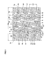
Fig. 1 is a development view of a tread portion showing a pneumatic tire according to an embodiment of the present invention; -
Fig. 2 is an enlarged vi ew of a center land porti on shown inFig. 1 ; - Fi g. 3 is an enl arged vi ew of a middle land porti on shown in
Fig. 1 ; and, -
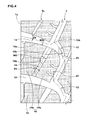
Fig. 4 is an enlarged view of a shoulder land portion shown inFig. 1 . - An embodiment of the present invention will be described below based on drawings.
- As shown in
Fig. 1 , a pneumatic tire (hereinafter, also referred to simply as "tire") 1 is preferably utilized as a tire for a passenger vehicle. - A tread porti on 2 of the pneumatic tire 1 of the embodiment is provided with a pair of center
main grooves 3 continuously extending in a tire circumferential direction on both sides of a tire equator C, and a pair of shouldermain grooves 4 continuously extending in the tire circumferential direction on outer si des of the centermain grooves 3. According ng to this, the tread portion 2 of the embodiment is divided into onecenter land portion 5a extending between the centermain grooves 3, a pair ofmiddle land portions 5b extending between the centermain grooves 3 and the shouldermain grooves 4, and a pair ofshoulder land portions 5c extending on outer sides of the shouldermain grooves 4 in a tire axial direction. A tread pattern of the embodiment is formed substantially into a point symmetric pattern around an arbitrary poi nt on the ti re equator C except variable pitch. - Groove widths of the center
main grooves 3 and the shoulder main grooves 4 (the groove widths are perpendicular to a longitudinal direction of the grooves, and this defi ni ti on is applied also to other grooves) w1 and w2 can variously be defined in accordance with customary practice. However, if the groove widths w1 and w2 and/or groove depths are excessively large, there is a possibility that a ground-contact area is reduced and ri gi di ti es of the land porti ons 5a to 5c are lowered and, on the other hand, if the groove widths and/or the groove depths are excessively small, there is a possibility that drainage performance is deteriorated. Hence, it is preferable that the groove widths w1 and w2 of the centermain grooves 3 and the shouldermain grooves 4 are in a range of 3.0 to 8.0% of the tread width TW, for example. The groove depths of the centermain grooves 3 and the shouldermain grooves 4 are preferably in a range of 11.0 to 15.0 mm. - Installation positions of the center
main grooves 3 and the shouldermain groove 4 are not especially limited, but a distance L1 between a center line G1 of the centermain groove 3 and the tire equator C in the tire axial direction is preferably in a range of 7 to 15% of the tread width TW. Similarly, a di stance L2 between a center line G2 of the shouldermain groove 4 and a ground-contact end Te in the tire axial direction is preferably in a range of 15 to 30% of the tread width TW. According to this, the rigidities of theland portions 5a to 5c are secured in well balance, and steering stability and uneven wear resistance can be enhanced. The center lines G1 and G2 of the embodiment are formed into corrugated non-linear shapes, and the distances L1 and L2 in the ti re axial direction are speci fi ed by cente rs of amplitudes of the center lines G1 and G2. - The tread width TW is a distance between the ground-contact ends Te in the following state: i.e., a normal load is applied to the pneumatic ti re 1 in a normal state where a tire is mounted around a normal rim and normal internal pressure is charged into the ti re, and the ti re is brought into contact with a flat surface at a camber angle of 0°. Sizes of various portions of the ti re are values as measured in the normal state unless otherwise specified.
- The "normal rim" is a rim determined for each tire by a specification standard including a specification on which the tire is based, and is a "standard rim" specified in JATMA, a "Design Rim" in TRA, and a "Measuring Rim" in ETRTO.
- Further, the "normal internal pressure" is an air pressure determined for each tire by the specification standard including the specification on which the tire is based, and is "a maximum air pressure" specified in JATMA, a maximum value described in "TIRE LOAD LIMITS AT VARIOUS COLD INFLATION PRESSURES" in TRA, and "INFLATION PRESSURE" in ETRTO. when the tire is for a passenger vehicle, the normal internal pressure is 180 kPa.
- Further, the "normal load" is a load determined for each tire by the specification standard including the specification on which the tire is based, and is "maximum load ability" specified in JATMA, a maximum value described in the Table "TIRE LOAD LIMITS AT VARIOUS COLD INFLATION PRESSURES" in TRA, and a "LOAD CAPACITY" in ETRTO. When the tire is for a passenger vehicle, the normal load is 88% of each of the above loads.
- As shown in
Fig. 2 in a close-up manner, each of the centermain grooves 3 is formed into a zigzag shape by connectingarc groove pieces 6 to one another in the tire circumferential direction. Each of thearc groove pieces 6 includes anarc portion 7 which is curved to swell toward the tire equator C (rightward in the case of the tread half located on the left side of the tire equator C). That is, each of the centermain grooves 3 is formed such that thearc groove piece 6 is a minimum configuration unit of repeated patterns. Such anarc groove piece 6 prevents rigidity of thecenter land portion 5a from being deteriorated, and can efficiently discharge a water film between a road surface and a portion of the tread portion 2 near the tire equator C. Therefore, drainage performance is enhanced without impairing straight stability. Furthermore, thearc groove piece 6 enhances the rigidity of themiddle land portion 5b in the tire axial direction, thereby helping to enhance the uneven wear resistance of the tire. - In the tread half on the left side of the tire equator C in
Fig. 2 , each of thearc groove pieces 6 of this embodiment includes thearc portion 7 and astraight portion 8. Thestraight portion 8 includes agroove edge 6a on the side of the tire equator C forming an intersection portion K of thearc groove pieces 6. Thegroove edge 6a straightly extends in the tire circumferential direction. Such astraight portion 8 is of help to smoothly discharge drainage in the centermain groove 3 toward a last-come side of a rotation direction utilizing rotation of the tire. Since thestraight portion 8 is of help to secure rigidity of thecenter land portion 5a in the tire circumferential direction, the uneven wear resistance and steering stability can be maintained. - It is necessary that a zigzag amplitude a1 of the center
main groove 3 is in a range of 2 to 5% of the tread width TW. If the zigzag amplitude a1 i s smaller than 2% of the tread wi dth TW, a water film on the tread portion 2 near the tire equator C cannot be discharged efficiently. If the zigzag amplitude a1 exceeds 5% of the tread width TW on the other hand, the rigidity of thecenter land portion 5a is excessively lowered, and the uneven wear resistance and the steering stability are deteriorated. From such a viewpoint, the zigzag amplitude a1 is preferably 2.5% or more and 4.5% or less of the tread width TW. The amplitude a1 is equal to a distance in the tire axial direction between an outermost point Po of the center line G1 of the centermain groove 3 in the tire axial direction and an innermost point Pi of the center line G1 in the tire axial direction (hereinafter, this definition is also applied to amplitudes of other grooves). - To further exert the above-described effect, an angle (angle of tangent) θ1 between the center
main groove 3 and the tire circumferential direction is preferably 5° or more, and more preferably 15° or more, and preferably 40° or less, and more preferably 30° or less. - As shown in
Fig. 3 , the middle land porti on 5b is provided with a middleinclined groove 9. The middleinclined groove 9 extends to the shouldermain groove 4 from the intersection portion K at which thearc groove pieces 6 that are adjacent to each other in the tire circumferential direction in the centermain groove 3 are connected to each other. The middleinclined groove 9 can guide a portion of drainage in the centermain groove 3 into the shouldermain groove 4 utilizing rotation of the tire. Therefore, the drainage performance is enhanced. - The middle
inclined groove 9 is formed at an angle θ2 of 12 to 30° with respect to the tire circumferential direction. If this angle θ2 exceeds 30°, a drainage resistance in the middleinclined groove 9 is increased to deteriorate the drainage performance. If the angle θ2 is smaller than 12° on the contrary, the rigidity of themiddle land portion 5b between the middleinclined groove 9 and the centermain groove 3 is reduced to deteriorate the uneven wear resistance and the steering stability. From such a viewpoint, it is preferable that the angle θ2 is 14° or more and 28° or less. - A ti p end angle α1 of the middle land porti on 5b sandwiched between the middle
inclined groove 9 and the centermain groove 3 is in a range of 30 to 75°. If the tip end angle α1 exceeds 75°, drainage in the centermain groove 3 is less prone to flow toward the last-come side of the centermain groove 3 in the tire rotation direction and/or the middleinclined groove 9 to deteriorate the drainage performance. If the tip end angle α1 is less than 30° on the other hand, the ri gi di ty of the mi ddl eland portion 5b is lowered to deteriorate the uneven wear resistance and the steering stability. From such a viewpoint, it is preferable that the tip end angle α1 is 35° or more and 70° or less. When a tip end portion of themiddle land portion 5b is formed into an arc shape, the tip end angle α1 should be an angle between tangents of a land edge (not shown) of themiddle land portion 5b located 2 mm away from a tip end 5b1 in the tire circumferential direction. - A groove width w3 of the middle
inclined groove 9 is gradually reduced from the tire equator C toward the ground-contact end Te. Such a middleinclined groove 9 increases a flowing speed of drainage from the tire equator C toward the ground-contact end Te. Therefore, the drainage in the centermain groove 3 is prone to be smoothly discharged toward the ground-contact end Te. Rigidity of such a middleinclined groove 9 is relatively increased in a region on an outer side of themiddle land portion 5b in the tire axial direction where a ground-contact pressure is prone to be increased at the time of cornering. Therefore, the drainage performance and the uneven wear resistance are maintained in well balance. From such a viewpoint, the tread width Tw of the groove width W3 is preferably 2.0% or more, more preferably 2.5% or more, and preferably 4.0% or less, and more preferably 3.5% or less. - Further, from such a viewpoint, a groove depth of the middle
inclined groove 9 is preferably 50% or more of a groove depth of the centermain groove 3, more preferably 55% or more, and preferably 70% or less, and more preferably 65% or less. The groove depth of the mi ddl einclined groove 9 may be constant, but to ensure the rigidity of themiddle land portion 5b in the intermediate term of wear, the middleinclined groove 9 may be provided with astep portion 9c in which the groove depth is gradually reduced toward the shouldermain groove 4. To secure the drainage performance and the rigidity of themiddle land portion 5b in well balance, it is preferable that thestep portion 9c is provided at a position of 45 to 55% of a length L3 of the middleinclined groove 9 in the ti re circumferential direction. - It is preferable that a
groove edge 9a of the middleinclined groove 9 of the embodiment on an outer side in the tire axial direction and agroove edge 6b of thearc groove piece 6 on an outer side in the ti re axial direction are smoothly connected to each other. According to this, high rigidity of themiddle land portion 5b is maintained, and water can smoothly be discharged from thearc groove piece 6 of the centermain groove 3 to the middleinclined groove 9. - An outer end of the middle
inclined groove 9 of the embodiment in the tire axial direction is connected to the shouldermain groove 4. According to such a middleinclined groove 9, drainage in the centermain groove 3 can be di scharged to the ground-contact end Te and/or the last-come side in the tire rotation direction through the shouldermain groove 4, thereby further enhancing the drainage performance. - The
middle land portion 5b includesmiddle blocks 11 which are provided at a distance from each other in the tire circumferential direction, the middle blocks 11 are divided by the shouldermain groove 4, the centermain groove 3, and the middleinclined grooves 9 by connecting the middleinclined grooves 9 to the shouldermain groove 4. - As shown in
Figs. 1 and4 , the shouldermain groove 4 is formed by connectingcurved groove pieces 12 to one another in the tire circumferential direction. Each of thecurved groove pieces 12 is curved to swell toward the tire equator C. That is, the shouldermain groove 4 is formed into a zigzag shape such that thecurved groove piece 12 is a minimum configuration unit of repeated patterns. Such a shouldermain groove 4 effectively takes in awater film between a road surface and a shoulder portion of the tread portion 2, thereby enhancing the drainage performance. - It is preferable that the zigzag amplitude a2 of the
curved groove piece 12 is formed larger than the zigzag amplitude a1 of thearc groove piece 6. Rigidity of such acurved groove piece 12 is increased in theshoulder land portion 5c in the tire axial direction where a relatively large ground-contact pressure is applied at the time of cornering. Therefore, the steering stability is enhanced and generation of shoulder wear of theshoulder land portion 5c is suppressed. If the zigzag amplitude a2 is increased, there is a tendency that the rigidity of themiddle land portion 5b is reduced. Therefore, the zigzag amplitude a2 of thecurved groove piece 12 is preferably 3% or more of the tread width TW, more preferably 4% or more, and preferably 7% or less, and more preferably 6% or less. - Further, from such a viewpoint, an angle θ3 between the shoulder
main groove 4 and the tire circumferential direction is preferably 20° or more, more preferably 30° or more, and preferably 60° or less, and more preferably 55° or less. - As shown in
Fig. 1 , it is preferable that a length L4 of thecurved groove piece 12 in the tire circumferential direction is smaller than a length L5 of thearc groove piece 6 of the centermain groove 3 in the tire circumferential direction. That is, the number ofcurved groove pieces 12 of the larger zigzag amplitude a2 is greater than the number ofarc groove pieces 6. Therefore, the pneumatic tire 1 of the embodiment can obtain sufficient drainage performance at the shoulder portion. - As shown in
Fig. 4 , theshoulder land portion 5c includesshoulder lug grooves 13 which are provided at a distance from each other in the ti re circumferential direction, theshoulder lug grooves 13 extend from oneend 12a of thecurved groove piece 12 in the tire circumferential direction beyond the ground-contact end Te. According to this, theshoulder land portion 5c includes shoulder blocks 14 which are provided at a di stance from each other in the tire circumferential direction, the shoulder blocks 14 are divided by the shouldermain groove 4, the ground-contact end Te and theshoulder lug grooves 13. - In the embodiment, the
shoulder lug groove 13 is smoothly connected to theend 12a of thecurved groove piece 12. More specifically, in this embodiment, oneside groove edge 13a (lower side in this example) of theshoulder lug groove 13 in the tire circumferential direction and anouter side edge 12b of thecurved groove piece 12 in the tire axial direction are smoothly connected to each other. According to this, drainage resistance from the shouldermain groove 4 to theshoulder lug groove 13 is reduced, thereby obtaining excellent drainage performance. Since high rigidity of a corner portion of theshoulder block 14 is maintained, the uneven wear resistance is excellent. - To secure the drainage performance and the rigidity of the
shoulder block 14 in the tire circumferential direction in well balance, an angle θ4 of theshoulder lug groove 13 with respect to the tire axial direction is preferably 2° or more, more preferably 6° or more, and preferably 20° or less, and more preferably 16° or less. - To enhance the drainage performance, it is preferable that a groove width W4 of the
shoulder lug groove 13 is gradually increased toward the ground-contact end Te. To achieve balance between the drainage performance and the rigidity of theshoulder block 14, the groove width W4 is preferably 5.0 mm or more, more preferably 6.0 mm or more, and preferably 15.0 mm or less, and more preferably 13.5 mm or less. Similarly, a groove depth of theshoulder lug groove 13 is preferably 50% or more of a groove depth of the shouldermain groove 4, more preferably 55% or more, and preferably 70% or less, and more preferably 65% or less. - The
shoulder land portion 5c is provided with a shoulderinclined groove 15. The shoulder inclinedgroove 15 extends from oneend 12a of thecurved groove piece 12 of the shouldermain groove 4 in the tire circumferential direction to theshoulder lug groove 13 such that the shoulder inclinedgroove 15 has an opposite inclination to theshoulder lug groove 13 with respect to the tire axial direction. According to this, drainage in the shouldermain groove 4 can more effectively be discharged into theshoulder lug groove 13 and therefore into the ground-contact end Te through the shoulder inclinedgroove 15. - The
shoulder block 14 i s divided, by the shoulder inclinedgroove 15, into anouter shoulder block 14a on an outer side in the tire axial direction and aninner shoulder block 14b in the tire axial direction. - To ensure block rigidities of the
outer shoulder block 14a and theshoulder block 14b and to enhance the drainage performance, an angle θ5 of the shoulder inclinedgroove 15 with respect to the tire circumferential direction is preferably 15° or more, more preferably 20° or more, and preferably 55° or less, and more preferably 45° or less. Similarly, a groove width W5 of the shoulder inclinedgroove 15 is preferably 1.5% or more of the tread width TW, more preferably 2.5% or more, and preferably 4.5% or less, and more preferably 3.5% or less. A groove depth of the shoulder inclinedgroove 15 is preferably 15% or more of a groove depth of the shouldermain groove 4, more preferably 20% or more, and preferably 50% or less, and more preferably 40% or less. - The groove width W5 of the shoulder inclined
groove 15 may be constant, but may be gradually reduced toward the ground-contact end Te. The shoulder inclinedgroove 15 of the embodiment includes a reducedportion 15a whose groove width W5 is locally reduced. According to such a shoulderinclined groove 15, the flowing speed of drainage toward the ground-contact end Te can be increased and the drainage performance can further be enhanced while maintaining the rigidity of theshoulder block 14. - As shown in
Fig. 1 , in this embodiment, the shoulder inclinedgroove 15, thecurved groove piece 12, and the middleinclined groove 9 are smoothly connected with each other substantially straightly. That is, these grooves are connected to each other such that the middleinclined groove 9 continuously extends to theshoulder lug groove 13 through thecurved groove piece 12 and the shoulder inclinedgroove 15. Therefore, drainage in the centermain groove 3 is smoothly discharged to the ground-contact end Te, thereby further enhancing the drainage performance. - As shown in
Fig. 3 , the mi ddl eblock 11 includes a fi rst middleauxiliary groove 16 whose one end is connected to a top 12c of thecurved groove piece 12 of the shouldermain groove 4 on the side of the tire equator C and whose other end is connected to the intersection portion K of thearc groove piece 6 of the centermain groove 3, and a second middleauxiliary groove 17 which is deviated in position from the first middleauxiliary groove 16 in the tire circumferential direction and which connects thecurved groove piece 12 and the middleinclined groove 9 with each other. According to this, themiddle block 11 is divided into three blocks, i.e., afirst block 18 formed on the si de of the ti re equator C, athi rd block 20 formed on the side of the ground-contact end Te, and asecond block 19 located between thefi rst block 18 and thethi rd block 20. - A groove width W6 of the first middle
auxiliary groove 16 may be constant, but it is preferable that the first middleauxiliary groove 16 includes anenlarged portion 16a in which the groove width W6 is locally enlarged toward the ground-contact end Te. According to such a middleauxiliary groove 16, a large groove width on the side of the ground-contact end Te is secured and the drainage performance i s enhanced while maintaining rigidities of thefirst block 18 and thesecond block 19. - To achieve a balance between the enhancement of the drainage performance and the securement of rigidities of the fi rst to
third blocks 18 to 20, it is preferable that the groove width W6 of the first middle auxiliary groove is in a range of 5 to 10 mm, and a groove width W7 of the second middleauxiliary groove 17 is in a range of 1.5 to 3.5 mm. Similarly, a groove depth of the first middleauxiliary groove 16 and a groove depth of the second middleauxiliary groove 17 are preferably in a range of 55 to 65% of a groove depth of the centermain groove 3. The groove depth of the first middleauxiliary groove 16 may be constant, but to smoothen the drainage toward the ground-contact end Te, the first middleauxiliary groove 16 may be provided with astep portion 16b whose groove depth is gradually increased toward the ground-contact end Te. - The
second block 19 i s di vi ded by a thi rd mi ddl eauxiliary groove 21 into a secondinner block 19a on the side of the tire equator C and a secondouter block 19b on the side of the ground-contact end Te. One end of the third middleauxiliary groove 21 is connected to a portion of thecurved groove piece 12 near its top on the side of the ti re equator C, and the other end of the third middleauxiliary groove 21 is connected to the first middleauxiliary groove 16. - To achieve a balance between the rigidity of the
second block 19 and the enhancement of the drainage performance, it is preferable that a groove width W8 of the third middleauxiliary groove 21 is in a range of 2 to 5 mm, and a groove depth of the third middleauxiliary groove 21 is in a range of 2 to 5% of the groove depth of the centermain groove 3. An angle θ6 of the thi rd middleauxiliary groove 21 wi th respect to the tire circumferential direction is preferably in a range of 15 to 35°. - As shown in
Fig. 3 , since theshoulder lug grooves 13 are formed on outer sides of the secondouter block 19b and thethi rd block 20 in the ti re axial direction in this embodiment, a large ground-contact pressure is prone to be applied to the secondouter block 19b and thethird block 20. Therefore, to enhance the uneven wear resistance, it is preferable that a tread area of the secondouter block 19b and a tread area of thethi rd block 20 whi ch are adjacent to each other in the ti re circumferential direction are substantially equal to each other. More preferably, it is preferable that a difference between the tread area S2b of the secondouter block 19b and the tread area S3 of thethird block 20 is 30% or less of the tread area S2b or S3 of smaller one of the secondouter block 19b or thethird block 20, and more preferably 15% or less. - In this embodi ment, the
fi rst block 18 has a substantially triangular shape formed between the middleinclined groove 9 and the centermain groove 3. On the other hand, the secondinner block 19a, the secondouter block 19b and thethi rd block 20 have substantially rectangular shapes. Hence, in themiddle land portion 5b of the embodiment, the rigidity of thefirst block 18 is prone to be the smallest, and there is a tendency that uneven wear is easily generated in thefirst block 18. Hence, it is necessary to relatively increase the tread area of thefi rst block 18, and to enhance the uneven wear resistance. From such a viewpoint, it is preferable that a tread area S1 of thefirst block 18 is formed larger than the tread area S2a of the secondinner block 19a, the tread area S2b of the secondouter block 19b, and the tread area S3 of thethird block 20. - On the other hand, if the tread area S1 of the
fi rst block 18 becomes large, a rigidity balance between the secondinner block 19a, the secondouter block 19b, and thethird block 20 is deteriorated, and there is a possibility that the uneven wear resistance is lowered. From such a viewpoint, it is preferable that the tread area S2a of the secondinner block 19a, the tread area S2b of the secondouter block 19b, and the tread area S3 of thethi rd block 20 are 40% or more of the tread area S1 of thefirst block 18, more preferably 50% or more, and preferably 90% or less, and more preferably 80% or less. - The
first block 18 is provided with amiddle lug groove 25 which extends from the first middleauxiliary groove 16 toward the middleinclined groove 9 and terminates without coming into contact with the middleinclined groove 9. Such amiddle lug groove 25 is of help to moderate the rigidity of thefirst block 18 and to exert the uneven wear resistance. - In the embodiment, as shown in
Figs. 1 and3 , the first middleauxiliary groove 16, thecurved groove piece 12 and theshoulder lug groove 13 are smoothly connected to each other. That is, they are connected to each other such that the first middleauxiliary groove 16 substantially continuously extends to theshoulder lug groove 13 through thecurved groove piece 12. similarly, the second middleauxiliary groove 17, thecurved groove piece 12 and theshoulder lug groove 13 are smoothly connected to each other. That is, they are connected to each other such that the second middleauxiliary groove 17 substantially continuously extends to theshoulder lug groove 13 through thecurved groove piece 12. According to this, drainage in the centermain groove 3 and/or the middleinclined groove 9 is more smoothly discharged to the ground-contact end Te, thereby further enhancing the drainage performance. - A drainage path formed by the first middle
auxiliary groove 16, thecurved groove piece 12 and theshoulder lug groove 13, and a drainage path formed by the second middleauxiliary groove 17, thecurved groove piece 12 and theshoulder lug groove 13 are inclined diagonally left up in the example of the tread portion 2 on the left side of the tire equator C inFig. 1 . On the other hand, a drainage path formed by the middleinclined groove 9, thecurved groove piece 12 and the shoulder inclinedgroove 15 is inclined diagonally left down in this example. Therefore, the pneumatic tire 1 of the embodiment can exert great drainage performance without depending upon the tire rotation direction. - As shown in
Fig. 2 , thecenter land portion 5a includescenter slots 22 which are provided at a di stance from each other in the tire circumferential direction, thecenter slots 22 extend from thearc groove pieces 6 with an inclination in the same direction as that of the middleinclined groove 9 and terminate without reaching the tire equator C. Sincesuch center slots 22 can more reliably discharge a water film between a road surface and the tread portion 2 on the side of the tire equator C, it is possible to further enhance the drainage performance. Especially, since a groove width W9 of thecenter slot 22 of the embodiment is gradually increased toward the centermain groove 3, it is possible to reliably discharge the water film. - The
center land portion 5a is provided with a plurality of centerlateral grooves 23 coming across thecenter land portion 5a. The centerlateral grooves 23 are inclined with respect to the tire axial direction. - It is preferable that the
center land portion 5a is provided with a chamferedportion 10 formed by diagonally notching thestraight portion 8 in a constant width. Such a chamferedportion 10 is of help to moderate stress concentration generated on thegroove edge 6a on the side of the tire equator C to whi ch a relatively large ground-contact pressure is applied at the time of straight running, and to enhance the uneven wear resistance. - As shown in
Fig. 1 , it is preferable that thecenter land portion 5a, thethird block 20 and theinner shoulder block 14b of the embodiment are provided withsipings 24. Such sipings 24 are of help to moderate the rigidity of the blocks provided with the sipings, and to exert the uneven wear resistance. It is preferable that a siping width of thesiping 24 is in a range of 1.5 to 3.5 mm, a depth thereof is in a range of 20 to 30% of a groove depth of the centermain groove 3, and a length of thesiping 24 in the tire axial direction is in a range of 40 to 60% of a width of each block in the tire axial direction. - Although the embodiment of the invention has been described in detail, the invention is not limited to the embodiment and the invention can variously be modified and carried out of course.
- To confi rm the effects of the invention, pneumatic tires (size LT315/75R16 121S) having the pattern shown in
Fig. 1 were prototyped based on the specification shown in Table 1. various ki nds of performances of them were eval uated. Concrete sizes are as follows. All of conditions except the specification of Table 1 are the same. - Groove width W1/ground-contact width TW: 3.5 to 6.0%
- Groove depth: 12.8 to 13.2 mm
- Angle θ1 wi th respect to ti re circumferential direction: 15 to 25°
- Installation position L1/TW: 8%
- Groove width w2/ground-contact width TW: 3.0 to 4.5%
- Groove depth: 12.8 to 13.2 mm
- Angle θ3 with respect to ti re circumferential direction: 25 to 35°
- Installation position L2/TW: 18%
- Groove width W3: 1.6 to 3.6 mm
- Groove depth: 3.0 to 8.2 mm
- Groove width W4: 2.5 to 6.5 mm
- Groove depth: 7.2 to 13.7 mm
- Angle θ4 with respect to tire axial direction: 6.5 to 14.0°
- Groove width W5: 1.3 to 3.2 mm
- Groove depth: 2.8 to 5.2 mm
- Angle θ5 with respect to ti re circumferential direction: 27 to 38°
- Length L4 of curved groove pi ece in tire circumferential direction: 21.0 to 30.5 mm
- Length L5 of arc groove piece in tire circumferential direction: 43.0 to 59.5 mm
- Area ratio S2a/S1 between first block and second inner block: 53%
- Area ratio S3/S1 between first block and third block: 58%
- Tread width TW: 242 mm
- Test method is as follows:
- The prototyped ti res were assembled around rims of 16x8.0 and mounted on all of wheels of a four-wheel-drive vehicle of 4800cc displacement under conditions of an internal pressure of 275 kPa and a vertical load of 8.53 kN, only a driver rode in the vehicle, and a lane change was repeated at 60 km/h on a dry asphalt road of a tire test course. Steering stability of each test tire was evaluated in a five-point method by a driver's sensory evaluation. The greater the numeric value is, the more excellent the steering stability is.
- The prototyped tires were mounted on all of the wheels of the test vehicle under the above conditions, only a driver rode in the vehicle, and steering stability when a lane change was repeated at 60 km/h on a wet asphalt road of water depth of 4 to 6 mm was evaluated in a five-point method by a driver's sensory evaluation. The greater the numeric value is, the more excellent the steering stability is.
- The prototyped tires were mounted on all of the wheels of the test vehicle under the above conditions, the vehicle was made to run 24,000 km on a public road, and it was checked by the naked eye whether shoulder portions were unevenly worn. A degree of uneven wear was evaluated in a five-point method. The greater the numeric value is, the more excellent the result is.
- Results and the like of the test are shown in Table 1.
[Table 1-1] Com. Ex. 1 Com. Ex. 2 Ex. 1 Ex. 2 Ex. 3 Com. Ex. 3 Com. Ex. 4 Ex. 4 Ex. 5 Com. Ex. 5 Com. Ex. 6 Ratio a1/TW (%) between zigzag amplitude a1 of center main groove and tread width TW 1 6 3.5 2 5 3.5 3.5 3.5 3.5 3.5 3.5 Angle θ2 (°) of middle inclined groove 20 20 20 20 20 10 40 12 30 20 20 Tip end angle α1 (°) of land portion sandwiched between middle inclined groove and center main groove 45 45 45 45 45 45 45 45 45 20 80 Area ratio SPA/58 (%) of road surface 5 5 5 5 5 5 5 5 5 5 5 Ratio a2/TW between zigzag amplitude a2 of shoulder main groove and tread width TW 5 5 5 5 5 5 5 5 5 5 5 Drainage performance 3 2 5 4 3 5 1 5 3 4 1 Uneven wear resistance 3 3 5 5 4 2 5 3 5 2 3 steering stability 3 3 5 4 4 2 3 4 3 3 5 SA: absolute value of difference between tread area S2b of second outer block and tread area S3 of third block
SB: area of smaller one of tread area S2b of second outer block and tread area S3 of third block[Table 1-2] Ex. 6 Ex. 7 Ex. 8 Ex. 9 Ex. 10 Ex. 11 Ex. 12 Ex. 13 Ex. 14 Ex. 15 Ratio a1/TW (%) between zigzag amplitude a1 of center main groove and tread width TW 3.5 3.5 3.5 3.5 3.5 3.5 3.5 3.5 3.5 3.5 Angle θ2 (°) of middle inclined groove 20 20 20 20 20 20 20 20 20 20 Tip end angle α1 (°) of land portion sandwiched between middle inclined groove and center main groove 30 75 45 45 45 45 45 45 45 45 Area ratio SA/SB (%) of road surface 5 5 40 20 25 30 5 5 5 5 Ratio a2/TW between zigzag amplitude a2 of shoulder main groove and tread width TW 5 5 5 5 5 5 2 8 3 7 Drainage performance 4 3 5 5 5 5 4 5 4 5 uneven wear resistance 3 4 1 4 3 2 4 3 5 4 Steering stability 4 5 5 5 5 5 4 5 4 5 - As a result of the test, it could be confirmed that the steeri ng stability and the uneven wear resi stance of the ti res of the embodiment were enhanced while maintaining drainage performance compared with those of tires of the comparative examples.
Claims (9)
- A pneumatic tire in which a tread portion is provided with a pai r of center main grooves which continuously extend on both sides of a ti re equator in a ti re ci rcumferential direction, and a pair of shoulder main grooves which continuously extend on outer sides of the center main grooves in the tire circumferential direction, thereby dividing the tread portion into a center land portion located between the center main grooves, a middle land portion located between the center main groove and the shoulder main groove, and a pair of shoulder land portions which extend on outer sides of the shoul der mai n grooves in a tire axial direction, wherein
the center main groove is formed into a zigzag shape by connecting arc groove pieces to each other in the tire circumferential direction, each of the arc groove pieces includes an arc portion which is curved to swell toward the tire equator, a zigzag amplitude of the center main groove is 2 to 5% of a tread width,
the middle land portion is provided with a middle inclined groove extending from an intersection portion of the arc groove pieces toward the shoulder main groove at an angle of 12 to 30° with respect to the ti re circumferential di recti on,
a tip end angle of a land portion sandwiched between the middle inclined groove and the center main groove is 30 to 75°, and
a groove wi dth of the mi ddl e inclined groove is gradually reduced toward a ground-contact end. - The pneumatic tire according to claim 1, wherein the center main groove includes a straight portion in which a groove edge of the intersection portion of the arc groove pieces and on the side of the ti re equator straightly extends in the tire circumferential direction.
- The pneumatic tire according to claim 1 or 2, wherein the shoulder main groove is formed into a zigzag shape by connecting curved groove pieces to each other in the tire circumferential direction, each of the curved groove pieces is curved to swell toward the tire equator, and
a zigzag amplitude of the cu rved groove pi ece is larger than a zigzag amplitude of the arc groove piece. - The pneumatic tire according to claim 3, wherein the shoulder land portion is provided with a shoulder lug groove which extends from one ti re circumferential end of the curved groove piece beyond the ground-contact end at an angle of 2 to 20° with respect to the ti re circumferential direction, and a shoulder inclined groove which extends from one tire circumferential end of the curved groove piece to the shoulder lug groove at an angle of 15 to 55° with respect tot he tire circumferential direction such that the shoulder inclined groove has an opposite inclination to the shoulder lug groove.
- The pneumatic tire according to claim 4, wherein a groove width of the shoulder inclined groove is gradually reduced toward the ground-contact end.
- The pneumatic tire accordi ng to any one of claims 3 to 5, wherein a length of the curved groove piece in the tire circumferential direction is shorter than a length of the arc groove piece in the tire circumferential direction.
- The pneumatic ti re according to any one of claims 3 to 6,
wherein the middle land portion includes middle blocks which are provided at a distance from each other in the tire circumferential direction, the middle blocks are divided by the shoulder main groove, the center main groove, and the middle inclined grooves by connecting the middle inclined grooves to the shoulder main groove,
each of the middle blocks is divided into a first block on a side of the tire equator C, a third block on a side of the ground-contact end Te, and a second block between the fi rst block and the third block by a first middle auxiliary groove which connects the shoulder main groove and the arc groove piece of the center main groove with each other and by a second middle auxiliary groove which connects the curved groove piece and the middle inclined groove with each other,
the second block is divided into a second inner block on the side of the tire equator and a second outer block on the side of the ground-contact end Te by a third middle auxiliary groove, one end of the thi rd middle auxiliary groove is connected to a portion of the curved groove piece near its top on the side of the tire equator and the other end thereof is connected to the first middle auxiliary groove, and
a difference between a tread area of the second outer block and a tread area of the third block is 30% or less of the tread area of smaller one of the second outer block and the third block. - The pneumatic tire according to claim 7, wherein a tread area of the first block is larger than the each tread area of the second inner block, the second outer block and the third block.
- The pneumatic tire accordi ng to any one of claims 1 to 8, wherein center slots are provided in the center land portion at a distance from each other, each of the center slots extends from the arc groove piece with an inclination in the same direction as that of the middle inclined groove, and the center slot is terminated without reaching the tire equator C.
Applications Claiming Priority (1)
| Application Number | Priority Date | Filing Date | Title |
|---|---|---|---|
| JP2010249008A JP5081289B2 (en) | 2010-11-05 | 2010-11-05 | Pneumatic tire |
Publications (3)
| Publication Number | Publication Date |
|---|---|
| EP2450199A2 true EP2450199A2 (en) | 2012-05-09 |
| EP2450199A3 EP2450199A3 (en) | 2012-10-03 |
| EP2450199B1 EP2450199B1 (en) | 2013-07-31 |
Family
ID=45445695
Family Applications (1)
| Application Number | Title | Priority Date | Filing Date |
|---|---|---|---|
| EP11008555.2A Not-in-force EP2450199B1 (en) | 2010-11-05 | 2011-10-25 | Pneumatic tire |
Country Status (6)
| Country | Link |
|---|---|
| US (1) | US8813800B2 (en) |
| EP (1) | EP2450199B1 (en) |
| JP (1) | JP5081289B2 (en) |
| KR (1) | KR101754428B1 (en) |
| CN (1) | CN102555679B (en) |
| BR (1) | BRPI1107098A2 (en) |
Cited By (4)
| Publication number | Priority date | Publication date | Assignee | Title |
|---|---|---|---|---|
| EP2767415A3 (en) * | 2013-02-19 | 2014-12-03 | Sumitomo Rubber Industries, Ltd. | Pneumatic tire |
| EP2692546A4 (en) * | 2011-03-28 | 2015-06-03 | Bridgestone Corp | PNEUMATIC |
| WO2016082947A1 (en) * | 2014-11-25 | 2016-06-02 | Continental Reifen Deutschland Gmbh | Vehicle tires |
| CN119610952A (en) * | 2024-12-06 | 2025-03-14 | 天津万达轮胎有限公司 | A sand tire |
Families Citing this family (18)
| Publication number | Priority date | Publication date | Assignee | Title |
|---|---|---|---|---|
| USD684525S1 (en) * | 2011-04-22 | 2013-06-18 | Toyo Tire & Rubber Co., Ltd. | Tire |
| USD687765S1 (en) * | 2011-04-26 | 2013-08-13 | Toyo Tire & Rubber Co., Ltd. | Tire |
| JP5913192B2 (en) * | 2013-05-15 | 2016-04-27 | 住友ゴム工業株式会社 | Pneumatic tire |
| WO2016027647A1 (en) * | 2014-08-19 | 2016-02-25 | 横浜ゴム株式会社 | Pneumatic tire |
| KR101709240B1 (en) | 2016-06-20 | 2017-02-23 | (주)대우건설 | Mortar composition for recovering cross section of eco-friendly cement with sulphate resistance |
| JP6881962B2 (en) * | 2016-12-08 | 2021-06-02 | Toyo Tire株式会社 | Pneumatic tires |
| JP6838421B2 (en) * | 2017-02-16 | 2021-03-03 | 住友ゴム工業株式会社 | tire |
| JP7115132B2 (en) * | 2018-08-10 | 2022-08-09 | 横浜ゴム株式会社 | pneumatic tire |
| JP7198080B2 (en) * | 2018-12-27 | 2022-12-28 | Toyo Tire株式会社 | pneumatic tire |
| JP7268430B2 (en) * | 2019-03-20 | 2023-05-08 | 住友ゴム工業株式会社 | tire |
| JP7268431B2 (en) * | 2019-03-20 | 2023-05-08 | 住友ゴム工業株式会社 | tire |
| JP7255361B2 (en) * | 2019-05-31 | 2023-04-11 | 住友ゴム工業株式会社 | tire |
| JP7255363B2 (en) * | 2019-05-31 | 2023-04-11 | 住友ゴム工業株式会社 | tire |
| JP7255362B2 (en) * | 2019-05-31 | 2023-04-11 | 住友ゴム工業株式会社 | tire |
| JP7291032B2 (en) * | 2019-08-07 | 2023-06-14 | Toyo Tire株式会社 | pneumatic tire |
| CN112622530B (en) * | 2019-10-08 | 2024-03-08 | 住友橡胶工业株式会社 | Tire with a tire body |
| EP3838626B1 (en) | 2019-12-16 | 2023-04-26 | Sumitomo Rubber Industries, Ltd. | Tire |
| JP7495604B2 (en) * | 2020-04-30 | 2024-06-05 | 横浜ゴム株式会社 | tire |
Citations (1)
| Publication number | Priority date | Publication date | Assignee | Title |
|---|---|---|---|---|
| JP2000135904A (en) | 1998-10-30 | 2000-05-16 | Sumitomo Rubber Ind Ltd | Pneumatic tire |
Family Cites Families (18)
| Publication number | Priority date | Publication date | Assignee | Title |
|---|---|---|---|---|
| US4424843A (en) * | 1982-03-17 | 1984-01-10 | The Goodyear Tire & Rubber Company | Pneumatic tire tread |
| JPS60189608A (en) * | 1984-03-09 | 1985-09-27 | Yokohama Rubber Co Ltd:The | Pneumatic tire |
| JPS61157405A (en) * | 1984-12-28 | 1986-07-17 | Yokohama Rubber Co Ltd:The | Pneumatic tire |
| JPH0834211A (en) * | 1994-07-21 | 1996-02-06 | Bridgestone Corp | Pneumatic radial tire |
| JPH08276708A (en) * | 1995-04-07 | 1996-10-22 | Yokohama Rubber Co Ltd:The | Pneumatic tire for heavy duty |
| JP3177466B2 (en) * | 1997-02-06 | 2001-06-18 | 住友ゴム工業株式会社 | Pneumatic tire |
| JP4397494B2 (en) * | 2000-01-26 | 2010-01-13 | 住友ゴム工業株式会社 | Pneumatic tire |
| JP4275283B2 (en) * | 2000-02-16 | 2009-06-10 | 株式会社ブリヂストン | Pneumatic tire |
| JP4716551B2 (en) * | 2000-10-03 | 2011-07-06 | 株式会社ブリヂストン | Pneumatic tires for winter |
| JP4632593B2 (en) * | 2001-08-31 | 2011-02-16 | 住友ゴム工業株式会社 | Pneumatic tire |
| JP4596706B2 (en) * | 2001-08-31 | 2010-12-15 | 住友ゴム工業株式会社 | Pneumatic tire |
| JP4184674B2 (en) * | 2002-02-14 | 2008-11-19 | 株式会社ブリヂストン | Pneumatic tire |
| JP4869089B2 (en) * | 2007-01-22 | 2012-02-01 | 株式会社ブリヂストン | Pneumatic tire |
| JP5038739B2 (en) * | 2007-02-22 | 2012-10-03 | 住友ゴム工業株式会社 | studless tire |
| US8261789B2 (en) * | 2007-10-25 | 2012-09-11 | Continental Tire North America, Inc. | Tire tread having three different sipe types |
| JP4653831B2 (en) * | 2008-10-28 | 2011-03-16 | 住友ゴム工業株式会社 | Pneumatic tire |
| USD613242S1 (en) * | 2009-03-18 | 2010-04-06 | Sumitomo Rubber Industries, Ltd. | Tire for automobile |
| JP5222337B2 (en) * | 2010-09-27 | 2013-06-26 | 住友ゴム工業株式会社 | Pneumatic tire |
-
2010
- 2010-11-05 JP JP2010249008A patent/JP5081289B2/en not_active Expired - Fee Related
-
2011
- 2011-10-13 US US13/272,271 patent/US8813800B2/en not_active Expired - Fee Related
- 2011-10-25 EP EP11008555.2A patent/EP2450199B1/en not_active Not-in-force
- 2011-10-28 KR KR1020110111190A patent/KR101754428B1/en not_active Expired - Fee Related
- 2011-10-28 CN CN201110338977.0A patent/CN102555679B/en not_active Expired - Fee Related
- 2011-11-07 BR BRPI1107098-6A patent/BRPI1107098A2/en not_active Application Discontinuation
Patent Citations (1)
| Publication number | Priority date | Publication date | Assignee | Title |
|---|---|---|---|---|
| JP2000135904A (en) | 1998-10-30 | 2000-05-16 | Sumitomo Rubber Ind Ltd | Pneumatic tire |
Cited By (5)
| Publication number | Priority date | Publication date | Assignee | Title |
|---|---|---|---|---|
| EP2692546A4 (en) * | 2011-03-28 | 2015-06-03 | Bridgestone Corp | PNEUMATIC |
| US10137739B2 (en) | 2011-03-28 | 2018-11-27 | Bridgestone Corporation | Pneumatic tire |
| EP2767415A3 (en) * | 2013-02-19 | 2014-12-03 | Sumitomo Rubber Industries, Ltd. | Pneumatic tire |
| WO2016082947A1 (en) * | 2014-11-25 | 2016-06-02 | Continental Reifen Deutschland Gmbh | Vehicle tires |
| CN119610952A (en) * | 2024-12-06 | 2025-03-14 | 天津万达轮胎有限公司 | A sand tire |
Also Published As
| Publication number | Publication date |
|---|---|
| US8813800B2 (en) | 2014-08-26 |
| CN102555679B (en) | 2016-03-09 |
| BRPI1107098A2 (en) | 2013-04-24 |
| KR20120048487A (en) | 2012-05-15 |
| JP5081289B2 (en) | 2012-11-28 |
| EP2450199B1 (en) | 2013-07-31 |
| KR101754428B1 (en) | 2017-07-05 |
| CN102555679A (en) | 2012-07-11 |
| EP2450199A3 (en) | 2012-10-03 |
| JP2012101572A (en) | 2012-05-31 |
| US20120111466A1 (en) | 2012-05-10 |
Similar Documents
| Publication | Publication Date | Title |
|---|---|---|
| EP2450199B1 (en) | Pneumatic tire | |
| EP3326840B1 (en) | Tire | |
| EP3178668B1 (en) | Pneumatic tire | |
| EP3056359B1 (en) | Pneumatic tire | |
| EP2620299B1 (en) | Pneumatic tire | |
| EP2193935B1 (en) | Pneumatic tire with asymetric tread pattern | |
| EP3539798B1 (en) | Tyre | |
| EP2058143B1 (en) | Pneumatic tire | |
| EP3025875A1 (en) | Pneumatic tire | |
| EP3153333B1 (en) | Pneumatic tire | |
| EP2457746B1 (en) | Racing kart tire | |
| US20180178589A1 (en) | Tire | |
| EP2127907B1 (en) | Pneumatic tire | |
| EP3318421B1 (en) | Tire | |
| EP3375633B1 (en) | Tire | |
| EP2602127B1 (en) | Tire | |
| US20070163692A1 (en) | Pneumatic tire | |
| US8281828B2 (en) | Pneumatic tire with tread having lug grooves and sipes | |
| EP3323638B1 (en) | Tire | |
| EP2862728B1 (en) | Tire | |
| EP3970996B1 (en) | Tire | |
| EP2821257B1 (en) | Pneumatic tire | |
| EP3666552B1 (en) | Tyre | |
| EP3936351B1 (en) | Pneumatic tire | |
| EP3626483B1 (en) | Tyre |
Legal Events
| Date | Code | Title | Description |
|---|---|---|---|
| PUAI | Public reference made under article 153(3) epc to a published international application that has entered the european phase |
Free format text: ORIGINAL CODE: 0009012 |
|
| AK | Designated contracting states |
Kind code of ref document: A2 Designated state(s): AL AT BE BG CH CY CZ DE DK EE ES FI FR GB GR HR HU IE IS IT LI LT LU LV MC MK MT NL NO PL PT RO RS SE SI SK SM TR |
|
| AX | Request for extension of the european patent |
Extension state: BA ME |
|
| PUAL | Search report despatched |
Free format text: ORIGINAL CODE: 0009013 |
|
| AK | Designated contracting states |
Kind code of ref document: A3 Designated state(s): AL AT BE BG CH CY CZ DE DK EE ES FI FR GB GR HR HU IE IS IT LI LT LU LV MC MK MT NL NO PL PT RO RS SE SI SK SM TR |
|
| AX | Request for extension of the european patent |
Extension state: BA ME |
|
| RIC1 | Information provided on ipc code assigned before grant |
Ipc: B60C 11/11 20060101ALI20120827BHEP Ipc: B60C 11/03 20060101ALI20120827BHEP Ipc: B60C 11/04 20060101AFI20120827BHEP |
|
| 17P | Request for examination filed |
Effective date: 20130319 |
|
| GRAP | Despatch of communication of intention to grant a patent |
Free format text: ORIGINAL CODE: EPIDOSNIGR1 |
|
| RIC1 | Information provided on ipc code assigned before grant |
Ipc: B60C 11/03 20060101ALI20130418BHEP Ipc: B60C 11/11 20060101ALI20130418BHEP Ipc: B60C 11/04 20060101AFI20130418BHEP |
|
| INTG | Intention to grant announced |
Effective date: 20130513 |
|
| GRAS | Grant fee paid |
Free format text: ORIGINAL CODE: EPIDOSNIGR3 |
|
| GRAA | (expected) grant |
Free format text: ORIGINAL CODE: 0009210 |
|
| AK | Designated contracting states |
Kind code of ref document: B1 Designated state(s): AL AT BE BG CH CY CZ DE DK EE ES FI FR GB GR HR HU IE IS IT LI LT LU LV MC MK MT NL NO PL PT RO RS SE SI SK SM TR |
|
| REG | Reference to a national code |
Ref country code: GB Ref legal event code: FG4D Ref country code: CH Ref legal event code: EP |
|
| REG | Reference to a national code |
Ref country code: AT Ref legal event code: REF Ref document number: 624381 Country of ref document: AT Kind code of ref document: T Effective date: 20130815 |
|
| REG | Reference to a national code |
Ref country code: IE Ref legal event code: FG4D |
|
| REG | Reference to a national code |
Ref country code: DE Ref legal event code: R096 Ref document number: 602011002487 Country of ref document: DE Effective date: 20130926 |
|
| REG | Reference to a national code |
Ref country code: AT Ref legal event code: MK05 Ref document number: 624381 Country of ref document: AT Kind code of ref document: T Effective date: 20130731 |
|
| REG | Reference to a national code |
Ref country code: NL Ref legal event code: VDEP Effective date: 20130731 |
|
| REG | Reference to a national code |
Ref country code: LT Ref legal event code: MG4D |
|
| PG25 | Lapsed in a contracting state [announced via postgrant information from national office to epo] |
Ref country code: PT Free format text: LAPSE BECAUSE OF FAILURE TO SUBMIT A TRANSLATION OF THE DESCRIPTION OR TO PAY THE FEE WITHIN THE PRESCRIBED TIME-LIMIT Effective date: 20131202 Ref country code: BE Free format text: LAPSE BECAUSE OF FAILURE TO SUBMIT A TRANSLATION OF THE DESCRIPTION OR TO PAY THE FEE WITHIN THE PRESCRIBED TIME-LIMIT Effective date: 20130731 Ref country code: NO Free format text: LAPSE BECAUSE OF FAILURE TO SUBMIT A TRANSLATION OF THE DESCRIPTION OR TO PAY THE FEE WITHIN THE PRESCRIBED TIME-LIMIT Effective date: 20131031 Ref country code: IS Free format text: LAPSE BECAUSE OF FAILURE TO SUBMIT A TRANSLATION OF THE DESCRIPTION OR TO PAY THE FEE WITHIN THE PRESCRIBED TIME-LIMIT Effective date: 20131130 Ref country code: LT Free format text: LAPSE BECAUSE OF FAILURE TO SUBMIT A TRANSLATION OF THE DESCRIPTION OR TO PAY THE FEE WITHIN THE PRESCRIBED TIME-LIMIT Effective date: 20130731 Ref country code: AT Free format text: LAPSE BECAUSE OF FAILURE TO SUBMIT A TRANSLATION OF THE DESCRIPTION OR TO PAY THE FEE WITHIN THE PRESCRIBED TIME-LIMIT Effective date: 20130731 Ref country code: HR Free format text: LAPSE BECAUSE OF FAILURE TO SUBMIT A TRANSLATION OF THE DESCRIPTION OR TO PAY THE FEE WITHIN THE PRESCRIBED TIME-LIMIT Effective date: 20130731 Ref country code: CY Free format text: LAPSE BECAUSE OF FAILURE TO SUBMIT A TRANSLATION OF THE DESCRIPTION OR TO PAY THE FEE WITHIN THE PRESCRIBED TIME-LIMIT Effective date: 20130821 Ref country code: SE Free format text: LAPSE BECAUSE OF FAILURE TO SUBMIT A TRANSLATION OF THE DESCRIPTION OR TO PAY THE FEE WITHIN THE PRESCRIBED TIME-LIMIT Effective date: 20130731 |
|
| PG25 | Lapsed in a contracting state [announced via postgrant information from national office to epo] |
Ref country code: GR Free format text: LAPSE BECAUSE OF FAILURE TO SUBMIT A TRANSLATION OF THE DESCRIPTION OR TO PAY THE FEE WITHIN THE PRESCRIBED TIME-LIMIT Effective date: 20131101 Ref country code: NL Free format text: LAPSE BECAUSE OF FAILURE TO SUBMIT A TRANSLATION OF THE DESCRIPTION OR TO PAY THE FEE WITHIN THE PRESCRIBED TIME-LIMIT Effective date: 20130731 Ref country code: FI Free format text: LAPSE BECAUSE OF FAILURE TO SUBMIT A TRANSLATION OF THE DESCRIPTION OR TO PAY THE FEE WITHIN THE PRESCRIBED TIME-LIMIT Effective date: 20130731 Ref country code: SI Free format text: LAPSE BECAUSE OF FAILURE TO SUBMIT A TRANSLATION OF THE DESCRIPTION OR TO PAY THE FEE WITHIN THE PRESCRIBED TIME-LIMIT Effective date: 20130731 Ref country code: LV Free format text: LAPSE BECAUSE OF FAILURE TO SUBMIT A TRANSLATION OF THE DESCRIPTION OR TO PAY THE FEE WITHIN THE PRESCRIBED TIME-LIMIT Effective date: 20130731 Ref country code: PL Free format text: LAPSE BECAUSE OF FAILURE TO SUBMIT A TRANSLATION OF THE DESCRIPTION OR TO PAY THE FEE WITHIN THE PRESCRIBED TIME-LIMIT Effective date: 20130731 |
|
| PG25 | Lapsed in a contracting state [announced via postgrant information from national office to epo] |
Ref country code: CY Free format text: LAPSE BECAUSE OF FAILURE TO SUBMIT A TRANSLATION OF THE DESCRIPTION OR TO PAY THE FEE WITHIN THE PRESCRIBED TIME-LIMIT Effective date: 20130731 |
|
| PG25 | Lapsed in a contracting state [announced via postgrant information from national office to epo] |
Ref country code: EE Free format text: LAPSE BECAUSE OF FAILURE TO SUBMIT A TRANSLATION OF THE DESCRIPTION OR TO PAY THE FEE WITHIN THE PRESCRIBED TIME-LIMIT Effective date: 20130731 Ref country code: CZ Free format text: LAPSE BECAUSE OF FAILURE TO SUBMIT A TRANSLATION OF THE DESCRIPTION OR TO PAY THE FEE WITHIN THE PRESCRIBED TIME-LIMIT Effective date: 20130731 Ref country code: DK Free format text: LAPSE BECAUSE OF FAILURE TO SUBMIT A TRANSLATION OF THE DESCRIPTION OR TO PAY THE FEE WITHIN THE PRESCRIBED TIME-LIMIT Effective date: 20130731 Ref country code: RO Free format text: LAPSE BECAUSE OF FAILURE TO SUBMIT A TRANSLATION OF THE DESCRIPTION OR TO PAY THE FEE WITHIN THE PRESCRIBED TIME-LIMIT Effective date: 20130731 Ref country code: SK Free format text: LAPSE BECAUSE OF FAILURE TO SUBMIT A TRANSLATION OF THE DESCRIPTION OR TO PAY THE FEE WITHIN THE PRESCRIBED TIME-LIMIT Effective date: 20130731 |
|
| PG25 | Lapsed in a contracting state [announced via postgrant information from national office to epo] |
Ref country code: ES Free format text: LAPSE BECAUSE OF FAILURE TO SUBMIT A TRANSLATION OF THE DESCRIPTION OR TO PAY THE FEE WITHIN THE PRESCRIBED TIME-LIMIT Effective date: 20130731 Ref country code: MC Free format text: LAPSE BECAUSE OF FAILURE TO SUBMIT A TRANSLATION OF THE DESCRIPTION OR TO PAY THE FEE WITHIN THE PRESCRIBED TIME-LIMIT Effective date: 20130731 Ref country code: IT Free format text: LAPSE BECAUSE OF FAILURE TO SUBMIT A TRANSLATION OF THE DESCRIPTION OR TO PAY THE FEE WITHIN THE PRESCRIBED TIME-LIMIT Effective date: 20130731 |
|
| PLBE | No opposition filed within time limit |
Free format text: ORIGINAL CODE: 0009261 |
|
| STAA | Information on the status of an ep patent application or granted ep patent |
Free format text: STATUS: NO OPPOSITION FILED WITHIN TIME LIMIT |
|
| 26N | No opposition filed |
Effective date: 20140502 |
|
| REG | Reference to a national code |
Ref country code: IE Ref legal event code: MM4A |
|
| REG | Reference to a national code |
Ref country code: DE Ref legal event code: R097 Ref document number: 602011002487 Country of ref document: DE Effective date: 20140502 |
|
| PG25 | Lapsed in a contracting state [announced via postgrant information from national office to epo] |
Ref country code: IE Free format text: LAPSE BECAUSE OF NON-PAYMENT OF DUE FEES Effective date: 20131025 |
|
| PG25 | Lapsed in a contracting state [announced via postgrant information from national office to epo] |
Ref country code: SM Free format text: LAPSE BECAUSE OF FAILURE TO SUBMIT A TRANSLATION OF THE DESCRIPTION OR TO PAY THE FEE WITHIN THE PRESCRIBED TIME-LIMIT Effective date: 20130731 |
|
| REG | Reference to a national code |
Ref country code: CH Ref legal event code: PL |
|
| PG25 | Lapsed in a contracting state [announced via postgrant information from national office to epo] |
Ref country code: TR Free format text: LAPSE BECAUSE OF FAILURE TO SUBMIT A TRANSLATION OF THE DESCRIPTION OR TO PAY THE FEE WITHIN THE PRESCRIBED TIME-LIMIT Effective date: 20130731 |
|
| PG25 | Lapsed in a contracting state [announced via postgrant information from national office to epo] |
Ref country code: LI Free format text: LAPSE BECAUSE OF NON-PAYMENT OF DUE FEES Effective date: 20141031 Ref country code: LU Free format text: LAPSE BECAUSE OF NON-PAYMENT OF DUE FEES Effective date: 20131025 Ref country code: RS Free format text: LAPSE BECAUSE OF FAILURE TO SUBMIT A TRANSLATION OF THE DESCRIPTION OR TO PAY THE FEE WITHIN THE PRESCRIBED TIME-LIMIT Effective date: 20131031 Ref country code: MK Free format text: LAPSE BECAUSE OF FAILURE TO SUBMIT A TRANSLATION OF THE DESCRIPTION OR TO PAY THE FEE WITHIN THE PRESCRIBED TIME-LIMIT Effective date: 20130731 Ref country code: HU Free format text: LAPSE BECAUSE OF FAILURE TO SUBMIT A TRANSLATION OF THE DESCRIPTION OR TO PAY THE FEE WITHIN THE PRESCRIBED TIME-LIMIT; INVALID AB INITIO Effective date: 20111025 Ref country code: BG Free format text: LAPSE BECAUSE OF FAILURE TO SUBMIT A TRANSLATION OF THE DESCRIPTION OR TO PAY THE FEE WITHIN THE PRESCRIBED TIME-LIMIT Effective date: 20130731 Ref country code: CH Free format text: LAPSE BECAUSE OF NON-PAYMENT OF DUE FEES Effective date: 20141031 |
|
| PG25 | Lapsed in a contracting state [announced via postgrant information from national office to epo] |
Ref country code: MT Free format text: LAPSE BECAUSE OF FAILURE TO SUBMIT A TRANSLATION OF THE DESCRIPTION OR TO PAY THE FEE WITHIN THE PRESCRIBED TIME-LIMIT Effective date: 20130731 |
|
| GBPC | Gb: european patent ceased through non-payment of renewal fee |
Effective date: 20151025 |
|
| PG25 | Lapsed in a contracting state [announced via postgrant information from national office to epo] |
Ref country code: GB Free format text: LAPSE BECAUSE OF NON-PAYMENT OF DUE FEES Effective date: 20151025 |
|
| REG | Reference to a national code |
Ref country code: FR Ref legal event code: PLFP Year of fee payment: 6 |
|
| REG | Reference to a national code |
Ref country code: FR Ref legal event code: PLFP Year of fee payment: 7 |
|
| REG | Reference to a national code |
Ref country code: FR Ref legal event code: PLFP Year of fee payment: 8 |
|
| PG25 | Lapsed in a contracting state [announced via postgrant information from national office to epo] |
Ref country code: AL Free format text: LAPSE BECAUSE OF FAILURE TO SUBMIT A TRANSLATION OF THE DESCRIPTION OR TO PAY THE FEE WITHIN THE PRESCRIBED TIME-LIMIT Effective date: 20130731 |
|
| PGFP | Annual fee paid to national office [announced via postgrant information from national office to epo] |
Ref country code: FR Payment date: 20200914 Year of fee payment: 10 |
|
| PGFP | Annual fee paid to national office [announced via postgrant information from national office to epo] |
Ref country code: DE Payment date: 20201013 Year of fee payment: 10 |
|
| REG | Reference to a national code |
Ref country code: DE Ref legal event code: R119 Ref document number: 602011002487 Country of ref document: DE |
|
| PG25 | Lapsed in a contracting state [announced via postgrant information from national office to epo] |
Ref country code: DE Free format text: LAPSE BECAUSE OF NON-PAYMENT OF DUE FEES Effective date: 20220503 |
|
| PG25 | Lapsed in a contracting state [announced via postgrant information from national office to epo] |
Ref country code: FR Free format text: LAPSE BECAUSE OF NON-PAYMENT OF DUE FEES Effective date: 20211031 |