EP2450126A2 - Die casting system and method utilizing high melting temperature materials - Google Patents
Die casting system and method utilizing high melting temperature materials Download PDFInfo
- Publication number
- EP2450126A2 EP2450126A2 EP11187963A EP11187963A EP2450126A2 EP 2450126 A2 EP2450126 A2 EP 2450126A2 EP 11187963 A EP11187963 A EP 11187963A EP 11187963 A EP11187963 A EP 11187963A EP 2450126 A2 EP2450126 A2 EP 2450126A2
- Authority
- EP
- European Patent Office
- Prior art keywords
- die
- shot tube
- casting system
- die casting
- plunger
- Prior art date
- Legal status (The legal status is an assumption and is not a legal conclusion. Google has not performed a legal analysis and makes no representation as to the accuracy of the status listed.)
- Withdrawn
Links
Images

Classifications
-
- B—PERFORMING OPERATIONS; TRANSPORTING
- B22—CASTING; POWDER METALLURGY
- B22D—CASTING OF METALS; CASTING OF OTHER SUBSTANCES BY THE SAME PROCESSES OR DEVICES
- B22D17/00—Pressure die casting or injection die casting, i.e. casting in which the metal is forced into a mould under high pressure
- B22D17/20—Accessories: Details
- B22D17/2015—Means for forcing the molten metal into the die
- B22D17/2023—Nozzles or shot sleeves
-
- B—PERFORMING OPERATIONS; TRANSPORTING
- B22—CASTING; POWDER METALLURGY
- B22D—CASTING OF METALS; CASTING OF OTHER SUBSTANCES BY THE SAME PROCESSES OR DEVICES
- B22D17/00—Pressure die casting or injection die casting, i.e. casting in which the metal is forced into a mould under high pressure
- B22D17/20—Accessories: Details
- B22D17/22—Dies; Die plates; Die supports; Cooling equipment for dies; Accessories for loosening and ejecting castings from dies
- B22D17/2209—Selection of die materials
Definitions
- This disclosure relates generally to casting and, more particularly, to a die casting system for casting high temperature materials.
- Die casting involves injecting molten metal directly into a reusable die to yield a net-shaped component. Die casting has typically been used to produce components that do not require high thermal mechanical performance. For example, die casting is commonly used to produce components made from relatively low melting temperature metals, such as, but not limited to: aluminum, zinc, magnesium, and copper. The products produced from these alloy systems are not generally subjected to extreme operating conditions.
- Gas turbine engines include multiple components that are subjected to extreme temperatures during operation.
- the compressor section and turbine section of the gas turbine engine each include blades and vanes that are subjected to relatively extreme temperatures, such as temperatures exceeding approximately 1500°F (815°C).
- Gas turbine engine components for use in these applications are produced through several processes, such as, but not limited to, investment casting and forging.
- Investment casting involves pouring molten metal into a ceramic shell having a cavity in the shape of the component to be cast.
- the shape of the component to be produced is derived from a wax pattern or SLA pattern to form the exterior shape of the component.
- the investment casting process is capital intensive, requires significant manual labor, and can be time intensive to produce the final component.
- Forging of a component is accomplished through the application of localized forces to the desired metal using shaped tooling to plastically deform the metal into the final shape. While forging is generally less expensive than investment casting there is still a significant amount of lead time and capital investment required to produce components by this methodology. Wrought product can be subsequently machined into the desired shape, but is less cost effective for large volumes of components due to excessive material losses due to machining.
- An example die casting system includes a die comprised of a plurality of die components that define a die cavity, metal delivery system, and part removal system configured to receive a molten metal.
- One or more of the die components comprises a material or materials that are suitable for use with the molten metal and has a melting temperature above 815 degrees Celsius.
- An example die casting system includes a die comprised of a plurality of die components that define a die cavity configured to receive a molten metal, wherein at least one of the plurality of die components comprises a material selected from a group consisting of a nickel based super alloy, a cobalt based super alloy, an iron-nickel based super alloy, a suitably alloyed iron based alloy, a suitably alloyed copper alloy, and a refractory metal alloy where the refractory metal is either: tungsten, molybdenum, rehenium, niobium, or tantalum.
- An example die casting system includes a die comprised of a plurality of die components that define a die cavity configured to receive a molten metal that has a melting temperature above 815 degrees Celsius.
- One of the die components comprises a ceramic material, or a composite material such as: a metal matrix composite, a ceramic matrix composite, or a combination of independent ceramic and metallic components that comprise the die components.
- an example die casting system 50 including a reusable die 52 having a plurality of die elements 54, 56 that function to cast a component 55.
- a reusable die 52 having a plurality of die elements 54, 56 that function to cast a component 55.
- die elements 54, 56 are depicted in Figure 1 , it should be understood that the die 52 could include more or fewer die elements, as well as other parts and configurations.
- the die 52 is assembled by positioning the die elements 54, 56 together and holding the die elements 54, 56 at a desired positioning via a mechanism 58.
- the mechanism 58 could include a clamping mechanism of appropriate hydraulic, pneumatic, electromechanical and/or other configurations.
- the mechanism 58 also separates the die elements 54, 56 subsequent to casting.
- the die elements 54, 56 define internal surfaces 62 that cooperate to define a die cavity 60.
- a shot tube 64 is in fluid communication with the die cavity 60 via one or more ports 66 located in the die element 54, the die element 56, or both.
- a plunger tip and rod 68 are received within the shot tube 64 and is moveable between a retracted and injection position (in the direction of arrow A) within the shot tube 64 by a mechanism 80.
- the mechanism 80 could include a hydraulic assembly or other suitable mechanism, including, but not limited to, hydraulic, pneumatic, electromechanical, or any combination thereof.
- the shot tube 64 is positioned to receive a molten metal from a melting unit 82, such as a crucible, for example.
- the melting unit 82 may utilize any known technique for melting an ingot of metallic material to prepare a molten metal for delivery to the shot tube 64, including but not limited to, vacuum induction melting, electron beam melting, induction skull melting, and resistance melting.
- the molten metal to be used to manufacture the part is melted in the melting unit 82 at a location that is separate from the shot tube 64 and the die cavity 60.
- the melting unit 82 is positioned in close proximity to the shot tube 64 to reduce the required transfer distance between the molten metal and the shot tube 64.
- Example molten metals capable of being used to die cast a component 55 include, but are not limited to, nickel based super alloys, titanium alloys, high temperature aluminum alloys, copper based alloys, iron alloys, molybdenum, tungsten, niobium, or other refractory metals. This disclosure is not limited to the disclosed alloys, and it should be understood that any material having a high melting temperature may be utilized to die cast the component 55. As used herein, the term "high melting temperature” is intended to describe component materials having a melting temperature of approximately 1500°F (815°C) or higher.
- the molten metal is transferred from the melting unit 82 to the shot tube 64 in a known manner, such as pouring the molten metal into a pour hole 63 in the shot tube 64, for example.
- a sufficient amount of molten metal is poured into the shot tube 64 to fill the die cavity 60.
- the shot tube plunger 68 is actuated to inject the molten metal under pressure from the shot tube 64 into the die cavity 60 to cast the component 55.
- the die casting system 50 could be configured to cast multiple components in a single shot.
- the example die casting system 50 depicted in Figure 1 is illustrative only and could include more or less sections, parts and/or components. This disclosure extends to all forms of die casting, including but not limited to, horizontal or vertical, or inclined die casting systems.
- Figures 3A and 3B illustrate portions of the die casting system 50 during casting ( Figure 3A ) and after the die elements 54, 56 separate ( Figure 3B ).
- the die elements 54, 56 are disassembled relative to the component 55 by opening the die 52 via the mechanism 58.
- ejector pins 84 are used to move the component 55 from the die cavity 60.
- the example die casting system 50 includes portions that are made from high temperature system materials that are able to withstand high temperatures associated with casting the molten metal into the component 55.
- the die elements 54, 56 are made entirely of the high temperature system material.
- a portion of the die elements 54, 56 are made of the high temperature system material.
- the areas of the cavity 70 establishing areas of the component 55 prone to microfractures or thermo-mechanical induced fatigue, such as tight radii areas of the cast component, could be made of the high temperature system material.
- the areas of the die elements 54, 56 establishing the cavity could be coated with the high temperature system material.
- portions of the shot tube 64, the shot tube plunger 68, or the ejector pins 84 include the high temperature system material in some examples.
- the example high temperature system material does not reactively interact with the molten material. That is, there is no substantial chemical reaction, melting, welding, soldering, or alloying between the high temperature system material and the molten material.
- the die elements 54, 56 could incorporate the high temperature system material by casting, machining, slip casting, injection molding, isostatic pressing (hot or cold), sintering, stamping, forging, direct metal laser sintering etc.
- Example materials that could be used as the high temperature system material include metallic materials, such as a nickel based super alloy, a cobalt based super alloy, a iron-nickel based super alloy, a suitably alloyed iron based alloy, a suitably alloyed copper alloy, or a refractory metal (tungsten, molybdenum, rehenium, niobium, or tantalum) based alloy.
- metallic materials such as a nickel based super alloy, a cobalt based super alloy, a iron-nickel based super alloy, a suitably alloyed iron based alloy, a suitably alloyed copper alloy, or a refractory metal (tungsten, molybdenum, rehenium, niobium, or tantalum) based alloy.
- tungsten, molybdenum, rehenium, niobium, or tantalum refractory metal
- Example nickel based super alloys include: IN100, IN713C, IN792 forged; First generation nickel base single crystal alloys (0% Rhenium) such as those disclosed in US 4209348 and US4597809 ; Second generation nickel base single crystal alloys (3% Rhenium) such as those disclosed in US4719080 ; Third generation nickel base single crystal alloys (6% Rhenium) such as those disclosed in US5366695 ; Fourth generation nickel base single crystal alloys (6% Rhenium, 3% Ruthenium) such as those disclosed in US6007645 ; Fifth generation nickel base nickel base single crystal alloys (6+% Rhenium, 6+% Ruthenium) such as TMS-173; Directionally solidified first generation (0% Rhenium) columnar structure alloys such as those disclosed in US3785809 ; and second generation (3% Rhenium) columnar structure alloys such as those disclosed in US5068084 .
- Example nickel-iron super alloys include Invar 909, IN718.
- Example alloyed based iron alloys include: H23, H42, M35, M36, M42, M46, M62 and Greek Ascoloy.
- Example cobalt cast alloys include Mar-M-509, and Stellite 31.
- Example refractory metal alloys include: Anvilloy 1150, TZM (tungsten-molybdenum-zirconium), molybdenum-rhenium systems, tantalum -10% tungsten, and tungsten-rhenium systems.
- Example materials that can be used as the high temperature system material include ceramic materials, such as boron nitride, silicon nitride, silicon aluminum oxy nitride (SiAlON), aluminum nitride, aluminum oxide, silicon carbide, titanium carbide, tungsten carbide, zirconium oxide, boron carbide, titanium diboride, niobium boride, zirconium boride, hafnium diboride, niobium carbide, zirconium carbide, hafnium carbide, graphite etc.
- ceramic materials such as boron nitride, silicon nitride, silicon aluminum oxy nitride (SiAlON), aluminum nitride, aluminum oxide, silicon carbide, titanium carbide, tungsten carbide, zirconium oxide, boron carbide, titanium diboride, niobium boride, zirconium boride, hafnium diboride, niobium carbide
- Example materials that can be used as the high temperature system material include metal matrix composite materials, such as copper-tungsten, copper-molybdenum, copper-molybdenumcopper-copper, copper-niobium, Silvar, aluminium silicon carbide.
- Example materials that can be used as the high temperature system material include ceramic matrix composite materials, such as C-SiC, SiC-SiC, SiC-Si 3 N 4 , C-ZrC, C-HfC, C-SiC-ZrC, C-SiC-HfC, C-TaC and C-TaC-HfC.
- ceramic matrix composite materials such as C-SiC, SiC-SiC, SiC-Si 3 N 4 , C-ZrC, C-HfC, C-SiC-ZrC, C-SiC-HfC, C-TaC and C-TaC-HfC.
- the example component 55 is casted using the example die casting system 50 described above.
- the die casted component 55 is a blade for the gas turbine engine (not shown), such as a turbine blade for a turbine section of the gas turbine engine.
- this disclosure is not limited to the casting of blades.
- the example die casting system 50 of this disclosure may be utilized to cast aeronautical components including blades, vanes, combustor panels, blade outer air seals, or any other component subjected to extreme environments, including non-aeronautical components.
- the example component 55 includes tightly radiused areas 86 that are more susceptible to thermo mechanical fatigue that other areas of the component 55.
- the areas of the die elements 54, 56 that interface with the areas 86 include a layer of high temperature system material, for example.
- a die casting system that includes system materials that are have a relatively high melt point and that are non-reactive with a component material.
- the system materials facilitate die casting of components that are made from component materials having a high melt point.
- the system materials reduce thermo-mechanical fatigue in the cast component.
- the system materials are effective for moving thermal energy away from the cast component.
- the system materials absorb the heat input from molten metals.
Landscapes
- Engineering & Computer Science (AREA)
- Mechanical Engineering (AREA)
- Chemical & Material Sciences (AREA)
- Materials Engineering (AREA)
- Molds, Cores, And Manufacturing Methods Thereof (AREA)
- Turbine Rotor Nozzle Sealing (AREA)
Abstract
Description
- This disclosure relates generally to casting and, more particularly, to a die casting system for casting high temperature materials.
- Die casting involves injecting molten metal directly into a reusable die to yield a net-shaped component. Die casting has typically been used to produce components that do not require high thermal mechanical performance. For example, die casting is commonly used to produce components made from relatively low melting temperature metals, such as, but not limited to: aluminum, zinc, magnesium, and copper. The products produced from these alloy systems are not generally subjected to extreme operating conditions.
- Gas turbine engines include multiple components that are subjected to extreme temperatures during operation. For example, the compressor section and turbine section of the gas turbine engine each include blades and vanes that are subjected to relatively extreme temperatures, such as temperatures exceeding approximately 1500°F (815°C).
- Gas turbine engine components for use in these applications are produced through several processes, such as, but not limited to, investment casting and forging. Investment casting involves pouring molten metal into a ceramic shell having a cavity in the shape of the component to be cast. Generally, the shape of the component to be produced is derived from a wax pattern or SLA pattern to form the exterior shape of the component. The investment casting process is capital intensive, requires significant manual labor, and can be time intensive to produce the final component. Forging of a component is accomplished through the application of localized forces to the desired metal using shaped tooling to plastically deform the metal into the final shape. While forging is generally less expensive than investment casting there is still a significant amount of lead time and capital investment required to produce components by this methodology. Wrought product can be subsequently machined into the desired shape, but is less cost effective for large volumes of components due to excessive material losses due to machining.
- An example die casting system includes a die comprised of a plurality of die components that define a die cavity, metal delivery system, and part removal system configured to receive a molten metal. One or more of the die components comprises a material or materials that are suitable for use with the molten metal and has a melting temperature above 815 degrees Celsius.
- An example die casting system includes a die comprised of a plurality of die components that define a die cavity configured to receive a molten metal, wherein at least one of the plurality of die components comprises a material selected from a group consisting of a nickel based super alloy, a cobalt based super alloy, an iron-nickel based super alloy, a suitably alloyed iron based alloy, a suitably alloyed copper alloy, and a refractory metal alloy where the refractory metal is either: tungsten, molybdenum, rehenium, niobium, or tantalum.
- An example die casting system includes a die comprised of a plurality of die components that define a die cavity configured to receive a molten metal that has a melting temperature above 815 degrees Celsius. One of the die components comprises a ceramic material, or a composite material such as: a metal matrix composite, a ceramic matrix composite, or a combination of independent ceramic and metallic components that comprise the die components.
- The various features and advantages of this disclosure will become apparent to those skilled in the art from the following detailed description. The drawings that accompany the detailed description can be briefly described as follows.
-
-
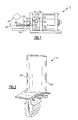
Figure 1 illustrates an example die casting system used to cast components. -
Figure 2 illustrates an example component cast with the die casting system ofFigure 1 . -
Figure 3A illustrates the die casting system ofFigure 1 during casting of a component. -
Figure 3B illustrates the die casting system ofFigure 1 upon separation from a cast component. - Referring to
Figures 1 and 2 , an exampledie casting system 50 including areusable die 52 having a plurality of dieelements component 55. Although twodie elements Figure 1 , it should be understood that the die 52 could include more or fewer die elements, as well as other parts and configurations. - The die 52 is assembled by positioning the die
elements elements mechanism 58. Themechanism 58 could include a clamping mechanism of appropriate hydraulic, pneumatic, electromechanical and/or other configurations. Themechanism 58 also separates the dieelements - The die
elements internal surfaces 62 that cooperate to define a diecavity 60. Ashot tube 64 is in fluid communication with thedie cavity 60 via one ormore ports 66 located in the dieelement 54, thedie element 56, or both. - A plunger tip and
rod 68 are received within theshot tube 64 and is moveable between a retracted and injection position (in the direction of arrow A) within theshot tube 64 by amechanism 80. Themechanism 80 could include a hydraulic assembly or other suitable mechanism, including, but not limited to, hydraulic, pneumatic, electromechanical, or any combination thereof. - The
shot tube 64 is positioned to receive a molten metal from amelting unit 82, such as a crucible, for example. Themelting unit 82 may utilize any known technique for melting an ingot of metallic material to prepare a molten metal for delivery to theshot tube 64, including but not limited to, vacuum induction melting, electron beam melting, induction skull melting, and resistance melting. The molten metal to be used to manufacture the part is melted in themelting unit 82 at a location that is separate from theshot tube 64 and thedie cavity 60. In this example, themelting unit 82 is positioned in close proximity to theshot tube 64 to reduce the required transfer distance between the molten metal and theshot tube 64. - Example molten metals capable of being used to die cast a
component 55 include, but are not limited to, nickel based super alloys, titanium alloys, high temperature aluminum alloys, copper based alloys, iron alloys, molybdenum, tungsten, niobium, or other refractory metals. This disclosure is not limited to the disclosed alloys, and it should be understood that any material having a high melting temperature may be utilized to die cast thecomponent 55. As used herein, the term "high melting temperature" is intended to describe component materials having a melting temperature of approximately 1500°F (815°C) or higher. - The molten metal is transferred from the
melting unit 82 to theshot tube 64 in a known manner, such as pouring the molten metal into apour hole 63 in theshot tube 64, for example. A sufficient amount of molten metal is poured into theshot tube 64 to fill thedie cavity 60. Theshot tube plunger 68 is actuated to inject the molten metal under pressure from theshot tube 64 into thedie cavity 60 to cast thecomponent 55. Although the casting of a single component is depicted, thedie casting system 50 could be configured to cast multiple components in a single shot. - The example
die casting system 50 depicted inFigure 1 is illustrative only and could include more or less sections, parts and/or components. This disclosure extends to all forms of die casting, including but not limited to, horizontal or vertical, or inclined die casting systems. -
Figures 3A and 3B illustrate portions of thedie casting system 50 during casting (Figure 3A ) and after the dieelements Figure 3B ). After the molten metal solidifies within the die cavity 70, the dieelements component 55 by opening the die 52 via themechanism 58. In one example,ejector pins 84 are used to move thecomponent 55 from thedie cavity 60. - The example
die casting system 50 includes portions that are made from high temperature system materials that are able to withstand high temperatures associated with casting the molten metal into thecomponent 55. - In one example, the die
elements - In another example, a portion of the
die elements component 55 prone to microfractures or thermo-mechanical induced fatigue, such as tight radii areas of the cast component, could be made of the high temperature system material. Also, the areas of thedie elements - In addition to the
die elements shot tube 64, theshot tube plunger 68, or theejector pins 84 include the high temperature system material in some examples. - Notably, the example high temperature system material does not reactively interact with the molten material. That is, there is no substantial chemical reaction, melting, welding, soldering, or alloying between the high temperature system material and the molten material.
- Many techniques could be used to incorporate the high temperature system material into the
die casting system 50. For example, the dieelements - Example materials that could be used as the high temperature system material include metallic materials, such as a nickel based super alloy, a cobalt based super alloy, a iron-nickel based super alloy, a suitably alloyed iron based alloy, a suitably alloyed copper alloy, or a refractory metal (tungsten, molybdenum, rehenium, niobium, or tantalum) based alloy. These materials can be manufactured into suitable die blocks using a variety or processing techniques including, but not limited to: cold forging, hot forging, conventional casting, directional solidified casings with or without orientation control, extrusions, or hot isostatic compaction of powder metallurgy products. Example nickel based super alloys include: IN100, IN713C, IN792 forged; First generation nickel base single crystal alloys (0% Rhenium) such as those disclosed in
US 4209348 andUS4597809 ; Second generation nickel base single crystal alloys (3% Rhenium) such as those disclosed inUS4719080 ; Third generation nickel base single crystal alloys (6% Rhenium) such as those disclosed inUS5366695 ; Fourth generation nickel base single crystal alloys (6% Rhenium, 3% Ruthenium) such as those disclosed inUS6007645 ; Fifth generation nickel base nickel base single crystal alloys (6+% Rhenium, 6+% Ruthenium) such as TMS-173; Directionally solidified first generation (0% Rhenium) columnar structure alloys such as those disclosed inUS3785809 ; and second generation (3% Rhenium) columnar structure alloys such as those disclosed inUS5068084 . Example nickel-iron super alloys include Invar 909, IN718. Example alloyed based iron alloys include: H23, H42, M35, M36, M42, M46, M62 and Greek Ascoloy. Example cobalt cast alloys include Mar-M-509, and Stellite 31. Example refractory metal alloys include: Anvilloy 1150, TZM (tungsten-molybdenum-zirconium), molybdenum-rhenium systems, tantalum -10% tungsten, and tungsten-rhenium systems. - Example materials that can be used as the high temperature system material include ceramic materials, such as boron nitride, silicon nitride, silicon aluminum oxy nitride (SiAlON), aluminum nitride, aluminum oxide, silicon carbide, titanium carbide, tungsten carbide, zirconium oxide, boron carbide, titanium diboride, niobium boride, zirconium boride, hafnium diboride, niobium carbide, zirconium carbide, hafnium carbide, graphite etc.
- Example materials that can be used as the high temperature system material include metal matrix composite materials, such as copper-tungsten, copper-molybdenum, copper-molybdenumcopper-copper, copper-niobium, Silvar, aluminium silicon carbide.
- Example materials that can be used as the high temperature system material include ceramic matrix composite materials, such as C-SiC, SiC-SiC, SiC-Si3N4, C-ZrC, C-HfC, C-SiC-ZrC, C-SiC-HfC, C-TaC and C-TaC-HfC.
- The
example component 55 is casted using the example diecasting system 50 described above. In this example, the die castedcomponent 55 is a blade for the gas turbine engine (not shown), such as a turbine blade for a turbine section of the gas turbine engine. However, this disclosure is not limited to the casting of blades. For example, the example diecasting system 50 of this disclosure may be utilized to cast aeronautical components including blades, vanes, combustor panels, blade outer air seals, or any other component subjected to extreme environments, including non-aeronautical components. - The
example component 55 includes tightly radiusedareas 86 that are more susceptible to thermo mechanical fatigue that other areas of thecomponent 55. The areas of thedie elements areas 86 include a layer of high temperature system material, for example. - Features of the disclosed examples include a die casting system that includes system materials that are have a relatively high melt point and that are non-reactive with a component material. The system materials facilitate die casting of components that are made from component materials having a high melt point. The system materials reduce thermo-mechanical fatigue in the cast component. The system materials are effective for moving thermal energy away from the cast component. The system materials absorb the heat input from molten metals.
- The preceding description is exemplary rather than limiting in nature. Variations and modifications to the disclosed examples may become apparent to those skilled in the art that do not necessarily depart from the essence of this disclosure. Thus, the scope of legal protection given to this disclosure can only be determined by studying the following claims.
Claims (15)
- A die casting system (50), comprising:a die (52) comprising a plurality of die components (54, 56) that define a die cavity (60) configured to receive a molten metal, wherein at least one of the plurality of die components (54, 56) comprises a material that is not reactive with the molten metal and has a melting temperature above 815 degrees Celsius.
- The die casting system of claim 1, comprising a shot tube (64) in fluid communication with said die cavity (60), a shot tube plunger (68) moveable within said shot tube (64) to communicate the molten metal into said die cavity, wherein at least one of the shot tube (64) and the shot tube plunger (68) comprises the material.
- The die casting system of claim 2, wherein a tip of the shot tube plunger (68) comprises the material.
- The die casting system of any preceding claim, comprising at least one ejector pin (84) configured to be moved relative to the die cavity, wherein the at least one ejector pin (84) comprises the material.
- A die casting system, comprising:a die (52) comprising of a plurality of die components (54, 56) that define a die cavity (60) configured to receive a molten metal, wherein at least one of the plurality of die components comprises a material selected from a group consisting of a nickel based super alloy, a cobalt based super alloy, an iron-nickel based super alloy, a suitably alloyed iron based alloy, a suitably alloyed copper alloy, and a refractory metal based alloy.
- The die casting system of claim 5, comprising a shot tube (64) in fluid communication with said die cavity (60) and a shot tube plunger (68) moveable within said shot tube (64) to communicate the molten metal into said die cavity (60), wherein at least one of the shot tube (64) and the shot tube plunger (68) comprises the material, for example wherein a tip of the shot tube plunger (68) comprises the material.
- The die casting system of claim 5 or 6, wherein the at least one of the plurality of die components comprises a die.
- The die casting system of claim 5, 6 or 7, wherein another of the plurality of die components comprises a material that is not in the group.
- The die casting system of any of claims 5 to 8, wherein the refractory metal comprises a material selected from a group consisting of tungsten, molybdenum, rehenium, niobium, and tantalum.
- A die casting system, comprising:a die comprising a plurality of die components (54, 56) that define a die cavity configured to receive a molten metal that has a melting temperature above 815 degrees Celsius, wherein at least one of the plurality of die components comprises a material that is a ceramic material, a metal matrix composite material, a ceramic matrix composite material, or some combination of these.
- The die casting system of claim 10, comprising a shot tube (64) in fluid communication with said die cavity (60) and a shot tube plunger (68) moveable within said shot tube (64) to communicate the molten metal into said die cavity (60), wherein at least one of the shot tube (64) and the shot tube plunger (68) comprises the material, for example wherein the leading contact surface of the plunger tip or the entire plunger comprises the material.
- The die casting system of claim 10 or 11, wherein the material comprises a material selected from a group consisting of boron nitride, silicon nitride, silicon aluminum oxy nitride (SiAlON), aluminum nitride, aluminum oxide, silicon carbide, titanium carbide, tungsten carbide, zirconium oxide, boron carbide, titanium diboride, niobium boride, zirconium boride, hafnium diboride, niobium carbide, zirconium carbide, hafnium carbide, and graphite.
- The die casting system of claim 12, comprising a shot tube (64) in fluid communication with said die cavity (60) and a shot tube plunger (28) moveable within said shot tube (64) to communicate the molten metal into said die cavity (60), wherein at least one of the die components and the shot tube plunger comprises the material.
- The die casting system of claim 10 or 11, wherein the metal matrix composite material comprises a material selected from a group consisting of copper-tungsten, copper-molybdenum, copper-molybdenumcopper-copper, copper-niobium, Silvar, aluminium silicon carbide; and/or wherein the ceramic material comprises a material selected from a group consisting of C-SiC, SiC-SiC, SiC-Si3N4, C-ZrC, C-HfC, C-SiC-ZrC, C-SiC-HfC, C-TaC and C-TaC-HfC.
- The die casting system of any of claims 5 to 14, comprising at least one ejector pin (84) configured to be moved relative to the die cavity (60), wherein the ejector pin (84) comprises the material.
Applications Claiming Priority (1)
| Application Number | Priority Date | Filing Date | Title |
|---|---|---|---|
| US12/940,263 US20120111526A1 (en) | 2010-11-05 | 2010-11-05 | Die casting system and method utilizing high melting temperature materials |
Publications (2)
| Publication Number | Publication Date |
|---|---|
| EP2450126A2 true EP2450126A2 (en) | 2012-05-09 |
| EP2450126A3 EP2450126A3 (en) | 2016-01-06 |
Family
ID=44905708
Family Applications (1)
| Application Number | Title | Priority Date | Filing Date |
|---|---|---|---|
| EP11187963.1A Withdrawn EP2450126A3 (en) | 2010-11-05 | 2011-11-04 | Die casting system and method utilizing high melting temperature materials |
Country Status (3)
| Country | Link |
|---|---|
| US (2) | US20120111526A1 (en) |
| EP (1) | EP2450126A3 (en) |
| SG (1) | SG180155A1 (en) |
Cited By (4)
| Publication number | Priority date | Publication date | Assignee | Title |
|---|---|---|---|---|
| WO2016039715A1 (en) * | 2014-09-08 | 2016-03-17 | Siemens Aktiengesellschaft | Hybrid die cast system for forming a component usable in a gas turbine engine |
| EP3287212A1 (en) * | 2016-08-26 | 2018-02-28 | United Technologies Corporation | Low modulus shot sleeve for high temperature die casting |
| EP3360624A1 (en) * | 2017-02-08 | 2018-08-15 | United Technologies Corporation | Axisymmetic single crystal shot tube for high temperature die casting |
| EP3409400A1 (en) * | 2017-05-30 | 2018-12-05 | United Technologies Corporation | Oxidation resistant shot sleeve for high temperature die casting and method of making |
Families Citing this family (1)
| Publication number | Priority date | Publication date | Assignee | Title |
|---|---|---|---|---|
| CN114737072B (en) * | 2022-04-21 | 2022-09-23 | 无锡凯斯特铸业有限公司 | A kind of K417G nickel-based superalloy refining preparation and forming method |
Citations (7)
| Publication number | Priority date | Publication date | Assignee | Title |
|---|---|---|---|---|
| US3785809A (en) | 1971-06-15 | 1974-01-15 | United Aircraft Corp | Nickel-base superalloy |
| US4209348A (en) | 1976-11-17 | 1980-06-24 | United Technologies Corporation | Heat treated superalloy single crystal article and process |
| US4597809A (en) | 1984-02-10 | 1986-07-01 | United Technologies Corporation | High strength hot corrosion resistant single crystals containing tantalum carbide |
| US4719080A (en) | 1985-06-10 | 1988-01-12 | United Technologies Corporation | Advanced high strength single crystal superalloy compositions |
| US5068084A (en) | 1986-01-02 | 1991-11-26 | United Technologies Corporation | Columnar grain superalloy articles |
| US5366695A (en) | 1992-06-29 | 1994-11-22 | Cannon-Muskegon Corporation | Single crystal nickel-based superalloy |
| US6007645A (en) | 1996-12-11 | 1999-12-28 | United Technologies Corporation | Advanced high strength, highly oxidation resistant single crystal superalloy compositions having low chromium content |
Family Cites Families (12)
| Publication number | Priority date | Publication date | Assignee | Title |
|---|---|---|---|---|
| US3201835A (en) * | 1963-03-11 | 1965-08-24 | Titanium Metals Corp | Casting refractory metals |
| US3532561A (en) * | 1967-05-11 | 1970-10-06 | Gen Electric | Ferrous metal die casting process and products |
| US3841846A (en) * | 1970-01-25 | 1974-10-15 | Mallory & Co Inc P R | Liquid phase sintered molybdenum base alloys having additives and shaping members made therefrom |
| US3810505A (en) * | 1970-12-07 | 1974-05-14 | R Cross | Die casting method |
| US3988118A (en) * | 1973-05-21 | 1976-10-26 | P. R. Mallory & Co., Inc. | Tungsten-nickel-iron-molybdenum alloys |
| JPS53105515A (en) * | 1977-02-25 | 1978-09-13 | Nissan Motor | Die cast tool |
| EP0225523B1 (en) * | 1985-11-30 | 1989-11-15 | Akio Nakano | Molding die for use in casting |
| JPH0730429B2 (en) * | 1986-12-16 | 1995-04-05 | 三菱マテリアル株式会社 | Dispersion-strengthened sintered alloy steel die for Zn and Zn alloy die casting |
| JPS63203262A (en) * | 1987-02-19 | 1988-08-23 | Hitachi Metals Ltd | Die |
| EP1013363B1 (en) * | 1998-12-23 | 2005-03-02 | United Technologies Corporation | Apparatus for die casting material having a high melting temperature |
| US20020005233A1 (en) * | 1998-12-23 | 2002-01-17 | John J. Schirra | Die cast nickel base superalloy articles |
| US6479013B1 (en) * | 2000-08-10 | 2002-11-12 | Sumitomo Metal Industries, Ltd. | Casting components made from a tool steel |
-
2010
- 2010-11-05 US US12/940,263 patent/US20120111526A1/en not_active Abandoned
-
2011
- 2011-11-04 EP EP11187963.1A patent/EP2450126A3/en not_active Withdrawn
- 2011-11-04 SG SG2011081452A patent/SG180155A1/en unknown
-
2019
- 2019-04-15 US US16/384,083 patent/US20190299278A1/en not_active Abandoned
Patent Citations (7)
| Publication number | Priority date | Publication date | Assignee | Title |
|---|---|---|---|---|
| US3785809A (en) | 1971-06-15 | 1974-01-15 | United Aircraft Corp | Nickel-base superalloy |
| US4209348A (en) | 1976-11-17 | 1980-06-24 | United Technologies Corporation | Heat treated superalloy single crystal article and process |
| US4597809A (en) | 1984-02-10 | 1986-07-01 | United Technologies Corporation | High strength hot corrosion resistant single crystals containing tantalum carbide |
| US4719080A (en) | 1985-06-10 | 1988-01-12 | United Technologies Corporation | Advanced high strength single crystal superalloy compositions |
| US5068084A (en) | 1986-01-02 | 1991-11-26 | United Technologies Corporation | Columnar grain superalloy articles |
| US5366695A (en) | 1992-06-29 | 1994-11-22 | Cannon-Muskegon Corporation | Single crystal nickel-based superalloy |
| US6007645A (en) | 1996-12-11 | 1999-12-28 | United Technologies Corporation | Advanced high strength, highly oxidation resistant single crystal superalloy compositions having low chromium content |
Cited By (6)
| Publication number | Priority date | Publication date | Assignee | Title |
|---|---|---|---|---|
| WO2016039715A1 (en) * | 2014-09-08 | 2016-03-17 | Siemens Aktiengesellschaft | Hybrid die cast system for forming a component usable in a gas turbine engine |
| CN106604791A (en) * | 2014-09-08 | 2017-04-26 | 西门子公司 | Hybrid die cast system for forming component usable in gas turbine engine |
| EP3287212A1 (en) * | 2016-08-26 | 2018-02-28 | United Technologies Corporation | Low modulus shot sleeve for high temperature die casting |
| US10245637B2 (en) | 2016-08-26 | 2019-04-02 | United Technologies Corporation | Low modulus shot sleeve for high temperature die casting |
| EP3360624A1 (en) * | 2017-02-08 | 2018-08-15 | United Technologies Corporation | Axisymmetic single crystal shot tube for high temperature die casting |
| EP3409400A1 (en) * | 2017-05-30 | 2018-12-05 | United Technologies Corporation | Oxidation resistant shot sleeve for high temperature die casting and method of making |
Also Published As
| Publication number | Publication date |
|---|---|
| US20120111526A1 (en) | 2012-05-10 |
| EP2450126A3 (en) | 2016-01-06 |
| US20190299278A1 (en) | 2019-10-03 |
| SG180155A1 (en) | 2012-05-30 |
Similar Documents
| Publication | Publication Date | Title |
|---|---|---|
| US20190299278A1 (en) | Die casting system and method utilizing high melting temperature materials | |
| US6676381B2 (en) | Method and apparatus for casting near-net shape articles | |
| EP2450125B1 (en) | Die casting system machine configurations | |
| US20210346947A1 (en) | Die casting system and method | |
| US9908175B2 (en) | Die casting system and method utilizing sacrificial core | |
| IL143931A (en) | Die casting of high melting temperature material | |
| EP2450127B1 (en) | High temperature die casting apparatus and method therefor | |
| EP2486994B1 (en) | Shot tube plunger for a die casting system | |
| US20160074933A1 (en) | Die casting of component having integral seal | |
| EP2450124A2 (en) | Shot tube plunger for a die casting system | |
| US7332123B2 (en) | Method for manufacturing composite articles and the articles obtained therefrom | |
| EP2450131B1 (en) | Melting unit for a die casting system | |
| EP3360624A1 (en) | Axisymmetic single crystal shot tube for high temperature die casting | |
| EP2841224A1 (en) | Shot tube plunger tip portion | |
| EP2574413A2 (en) | Method and system for die casting a hybrid component | |
| GB2536483B (en) | A method of Forming a Metal Component |
Legal Events
| Date | Code | Title | Description |
|---|---|---|---|
| PUAI | Public reference made under article 153(3) epc to a published international application that has entered the european phase |
Free format text: ORIGINAL CODE: 0009012 |
|
| AK | Designated contracting states |
Kind code of ref document: A2 Designated state(s): AL AT BE BG CH CY CZ DE DK EE ES FI FR GB GR HR HU IE IS IT LI LT LU LV MC MK MT NL NO PL PT RO RS SE SI SK SM TR |
|
| AX | Request for extension of the european patent |
Extension state: BA ME |
|
| PUAL | Search report despatched |
Free format text: ORIGINAL CODE: 0009013 |
|
| AK | Designated contracting states |
Kind code of ref document: A3 Designated state(s): AL AT BE BG CH CY CZ DE DK EE ES FI FR GB GR HR HU IE IS IT LI LT LU LV MC MK MT NL NO PL PT RO RS SE SI SK SM TR |
|
| AX | Request for extension of the european patent |
Extension state: BA ME |
|
| RIC1 | Information provided on ipc code assigned before grant |
Ipc: B22D 17/20 20060101AFI20151201BHEP Ipc: B22D 17/22 20060101ALI20151201BHEP |
|
| 17P | Request for examination filed |
Effective date: 20160706 |
|
| RBV | Designated contracting states (corrected) |
Designated state(s): AL AT BE BG CH CY CZ DE DK EE ES FI FR GB GR HR HU IE IS IT LI LT LU LV MC MK MT NL NO PL PT RO RS SE SI SK SM TR |
|
| RAP1 | Party data changed (applicant data changed or rights of an application transferred) |
Owner name: UNITED TECHNOLOGIES CORPORATION |
|
| STAA | Information on the status of an ep patent application or granted ep patent |
Free format text: STATUS: EXAMINATION IS IN PROGRESS |
|
| 17Q | First examination report despatched |
Effective date: 20180328 |
|
| STAA | Information on the status of an ep patent application or granted ep patent |
Free format text: STATUS: THE APPLICATION HAS BEEN WITHDRAWN |
|
| 18W | Application withdrawn |
Effective date: 20190902 |