EP2450119A1 - A shape adjusting tool - Google Patents
A shape adjusting tool Download PDFInfo
- Publication number
- EP2450119A1 EP2450119A1 EP11185551A EP11185551A EP2450119A1 EP 2450119 A1 EP2450119 A1 EP 2450119A1 EP 11185551 A EP11185551 A EP 11185551A EP 11185551 A EP11185551 A EP 11185551A EP 2450119 A1 EP2450119 A1 EP 2450119A1
- Authority
- EP
- European Patent Office
- Prior art keywords
- adjustment ring
- adjusting tool
- shape adjusting
- tool
- adjuster
- Prior art date
- Legal status (The legal status is an assumption and is not a legal conclusion. Google has not performed a legal analysis and makes no representation as to the accuracy of the status listed.)
- Granted
Links
Images

Classifications
-
- B—PERFORMING OPERATIONS; TRANSPORTING
- B21—MECHANICAL METAL-WORKING WITHOUT ESSENTIALLY REMOVING MATERIAL; PUNCHING METAL
- B21D—WORKING OR PROCESSING OF SHEET METAL OR METAL TUBES, RODS OR PROFILES WITHOUT ESSENTIALLY REMOVING MATERIAL; PUNCHING METAL
- B21D3/00—Straightening or restoring form of metal rods, metal tubes, metal profiles, or specific articles made therefrom, whether or not in combination with sheet metal parts
- B21D3/14—Recontouring
-
- B—PERFORMING OPERATIONS; TRANSPORTING
- B21—MECHANICAL METAL-WORKING WITHOUT ESSENTIALLY REMOVING MATERIAL; PUNCHING METAL
- B21C—MANUFACTURE OF METAL SHEETS, WIRE, RODS, TUBES, PROFILES OR LIKE SEMI-MANUFACTURED PRODUCTS OTHERWISE THAN BY ROLLING; AUXILIARY OPERATIONS USED IN CONNECTION WITH METAL-WORKING WITHOUT ESSENTIALLY REMOVING MATERIAL
- B21C37/00—Manufacture of metal sheets, rods, wire, tubes, profiles or like semi-manufactured products, not otherwise provided for; Manufacture of tubes of special shape
- B21C37/06—Manufacture of metal sheets, rods, wire, tubes, profiles or like semi-manufactured products, not otherwise provided for; Manufacture of tubes of special shape of tubes or metal hoses; Combined procedures for making tubes, e.g. for making multi-wall tubes
- B21C37/30—Finishing tubes, e.g. sizing, burnishing
-
- B—PERFORMING OPERATIONS; TRANSPORTING
- B29—WORKING OF PLASTICS; WORKING OF SUBSTANCES IN A PLASTIC STATE IN GENERAL
- B29C—SHAPING OR JOINING OF PLASTICS; SHAPING OF MATERIAL IN A PLASTIC STATE, NOT OTHERWISE PROVIDED FOR; AFTER-TREATMENT OF THE SHAPED PRODUCTS, e.g. REPAIRING
- B29C53/00—Shaping by bending, folding, twisting, straightening or flattening; Apparatus therefor
- B29C53/16—Straightening or flattening
- B29C53/20—Straightening or flattening of tubes
-
- Y—GENERAL TAGGING OF NEW TECHNOLOGICAL DEVELOPMENTS; GENERAL TAGGING OF CROSS-SECTIONAL TECHNOLOGIES SPANNING OVER SEVERAL SECTIONS OF THE IPC; TECHNICAL SUBJECTS COVERED BY FORMER USPC CROSS-REFERENCE ART COLLECTIONS [XRACs] AND DIGESTS
- Y10—TECHNICAL SUBJECTS COVERED BY FORMER USPC
- Y10T—TECHNICAL SUBJECTS COVERED BY FORMER US CLASSIFICATION
- Y10T29/00—Metal working
- Y10T29/49—Method of mechanical manufacture
- Y10T29/49718—Repairing
-
- Y—GENERAL TAGGING OF NEW TECHNOLOGICAL DEVELOPMENTS; GENERAL TAGGING OF CROSS-SECTIONAL TECHNOLOGIES SPANNING OVER SEVERAL SECTIONS OF THE IPC; TECHNICAL SUBJECTS COVERED BY FORMER USPC CROSS-REFERENCE ART COLLECTIONS [XRACs] AND DIGESTS
- Y10—TECHNICAL SUBJECTS COVERED BY FORMER USPC
- Y10T—TECHNICAL SUBJECTS COVERED BY FORMER US CLASSIFICATION
- Y10T29/00—Metal working
- Y10T29/49—Method of mechanical manufacture
- Y10T29/49718—Repairing
- Y10T29/49732—Repairing by attaching repair preform, e.g., remaking, restoring, or patching
-
- Y—GENERAL TAGGING OF NEW TECHNOLOGICAL DEVELOPMENTS; GENERAL TAGGING OF CROSS-SECTIONAL TECHNOLOGIES SPANNING OVER SEVERAL SECTIONS OF THE IPC; TECHNICAL SUBJECTS COVERED BY FORMER USPC CROSS-REFERENCE ART COLLECTIONS [XRACs] AND DIGESTS
- Y10—TECHNICAL SUBJECTS COVERED BY FORMER USPC
- Y10T—TECHNICAL SUBJECTS COVERED BY FORMER US CLASSIFICATION
- Y10T29/00—Metal working
- Y10T29/49—Method of mechanical manufacture
- Y10T29/49826—Assembling or joining
- Y10T29/49863—Assembling or joining with prestressing of part
- Y10T29/4987—Elastic joining of parts
- Y10T29/49872—Confining elastic part in socket
-
- Y—GENERAL TAGGING OF NEW TECHNOLOGICAL DEVELOPMENTS; GENERAL TAGGING OF CROSS-SECTIONAL TECHNOLOGIES SPANNING OVER SEVERAL SECTIONS OF THE IPC; TECHNICAL SUBJECTS COVERED BY FORMER USPC CROSS-REFERENCE ART COLLECTIONS [XRACs] AND DIGESTS
- Y10—TECHNICAL SUBJECTS COVERED BY FORMER USPC
- Y10T—TECHNICAL SUBJECTS COVERED BY FORMER US CLASSIFICATION
- Y10T29/00—Metal working
- Y10T29/51—Plural diverse manufacturing apparatus including means for metal shaping or assembling
- Y10T29/5176—Plural diverse manufacturing apparatus including means for metal shaping or assembling including machining means
- Y10T29/5177—Plural diverse manufacturing apparatus including means for metal shaping or assembling including machining means and work-holder for assembly
Definitions
- This invention relates to a shape adjusting tool, and is particularly, although not exclusively, concerned with a tool for correcting the circularity of hollow cylindrical components.
- split collets have been used which have an annular expander core which reduces obstruction, but the expander core is driven by an array of bolts distributed around it, and these must be tightened in exact unison to ensure equal expansion around the periphery of the split collet.
- a shape adjusting tool for adjusting the shape of a hollow component, the tool comprising a base structure carrying a plurality of adjuster elements which are distributed circumferentially about an axis of the tool, the tool also comprising an adjustment ring which is mounted on the base structure for rotation about the axis, a respective ramp arrangement being provided between each adjuster element and the adjustment ring whereby rotation of the adjustment ring about the axis causes radial displacement of each adjuster element.
- a shape adjusting tool in accordance with the present invention can be assembled from sheet metal parts, and consequently can be relatively light in weight. Also, the base structure can have an annular form to permit access to the interior of the hollow component while the shape adjusting tool is deployed.
- the adjustment ring may be resilient in the circumferential direction.
- the adjustment ring may include a circumferentially resilient element.
- the adjustment ring may comprise a plurality of segments, with the resilient element situated at one of the junctions between adjacent segments. The other junctions between adjacent segments may be rigid in the circumferential direction.
- Each segment may engage two of the adjuster elements through the respective ramp arrangements.
- the adjustment ring may comprise six of the segments, and may comprise twelve adjuster elements.
- Each ramp arrangement may comprise a ramp surface on the adjustment ring which directly engages the respective adjuster element.
- There may be a linear relationship between the angular position of the adjustment ring and the radial position of each adjuster element. The relationship may be the same for all of the adjuster elements, so that the adjuster elements move in unison on rotation of the adjustment ring.
- the adjustment ring may be supported on the base structure by bearing rollers which are distributed circumferentially about the axis.
- a respective roller may be provided at the same angular position as each adjuster element.
- each segment may be supported by two of the rollers.
- the tool may comprise means for rotating the adjustment ring.
- the rotating means may comprise a circumferentially extending rack on the adjustment ring and a pinion on the base structure.
- the adjusting tool may be adapted to engage the inside surface of the hollow component, in which case the ramp arrangements may be disposed to drive the adjustment elements radially outwards as the adjustment ring is rotated. In alternative embodiments, the adjusting tool may be adapted to engage the outer surface of the hollow component. Furthermore, although the adjusting tool may be configured to correct the circularity of a cylindrical hollow component, the adjuster elements may be disposed and actuated by means of the adjustment ring so as to correct the shape of a hollow component having a nominal shape which is non-circular.
- the tool comprises a base structure 2 comprising a supporting plate 4.
- the supporting plate 4 carries an array of adjuster elements 6 or plungers and an adjustment ring 8.
- the supporting plate 4 has a double-layered structure, comprising a base plate 10 and guide plates 12 which guide movement of the adjuster elements 6 and the adjustment ring 8 and which define the spacing between the base plate 10 and a cover plate 18.
- a circumferential inner web 14 and radial webs 16 are secured to the supporting plate 4 to enhance its rigidity.
- cover plates 18 are secured over the supporting plate 4 to retain the adjuster elements 6 and the adjustment ring 8.
- the cover plate is provided with a series of cut-outs, or windows, which permits visual access to portions of the adjustment ring when the cover plate is in position.
- the cover plates 18 are not shown in Figures 2 to 5 .
- the adjustment ring 8 comprises six identical segments 20, one of which is shown in Figure 3 .
- Each segment 20 has an undercut notch 22 at each end and subtends an angle between its ends of slightly less than 30 degrees.
- the segment 20 is fitted with a circumferentially extending toothed rack 24.
- a scale 28 is provided along each ramp surface 26, and part of each scale 28 is visible through a window 30 in the respective cover plate 18 (see Figure 1 ).
- Figure 4 shows, at least in part, three of the segments 20 mounted on the supporting plate 4.
- the middle one of the segments 20 is connected to the one to its left by a rigid link 32 which engages the respective notches 22 in the segments 20.
- the middle segment 20 is connected to the segment 20 on its right by a resilient link 34, which also engages the respective notches 22.
- Apart from the single resilient link 34 shown in Figure 4 all of the other junctions between adjacent segments 20 are made by way of rigid links 32.
- the adjustment ring 8 is supported for rotation on the supporting plate 4 by means of fixed-axis bearing rollers 36 which are distributed regularly around the supporting plate 4.
- Each segment 20 is supported by two rollers 36, and the resilient link 34 enables the circumferential length of the adjustment ring 8 to vary slightly in order to ensure that the adjustment ring 8 as a whole is in contact with each one of the rollers 36.
- the supporting plate 4 also carries a respective pinion 38 for the rack 24 of each segment 20.
- Each pinion 38 has a square, or otherwise non-circular, opening for receiving a drive tool.
- rollers 36 are at the same angular positions as the adjuster elements 6 around the adjustment ring 8. Consequently, forces applied to the adjuster elements 6 by the component to be corrected are transmitted through the segments 20 directly to the rollers 36, so causing no bending moment to be applied to the segments 20.
- the adjusting tool may be supported within the component to be corrected by any suitable means.
- a pivotable clip 42 is shown in Figure 2 , which can be swung into engagement with a flange at one end of the component in order to retain the tool in position.
- the tool is supported within the hollow component to be corrected or adjusted, for example by means of the clips 42, so that the tool sits perpendicular to the axis of the hollow component.
- the pinion 38 is then turned so as to displace the adjustment ring 8 to extend the adjuster elements 6 radially outwardly of the base structure 2.
- the ramp surfaces 26 are identical to each other, and consequently the adjuster elements 6 move in unison such that their radially outer tips always lie on a common radius from the central axis of the tool, as indicated at X in Figure 1 .
- the tips of the adjuster elements 6 are profiled to contact the inside surface of the component to be adjusted.
- the application of torque to the respective pinion 38 generates sufficient force at the tips of the adjuster elements 6 to deform the component to the desired shape, which would be circular in the embodiment described with reference to the drawings.
- the tool can thus be used to hold the component in the desired shape while further machining or other processing takes place on the component.
- each ramp 26, defined as radial displacement of the surface with respect to angular rotation of the adjustment ring 8 may be linear so that the scale 28 can represent the resulting displacement of the adjuster elements 6 from a nominal position in regular increments.
- the sheet metal components of the tool can be formed very accurately, for example by laser cutting, from sheets of an appropriate material, for example steel. It is consequently possible to manufacture the tool with very close tolerances so that accurate shape adjustment of hollow components can be achieved.
- the overall diameter of the tool i.e. diametrically from tip to tip of opposite elements 6 is:
- the radius R from the axis X to the centre of the mounting hole for the roller 36, is therefore critical and requires that the laser cut position of the hole is controlled as tightly as possible.
- the resulting roundness tolerance for the plungers has been measured and seen to be consistently better than 0.1 mm.
- the ramp surface 26 may have a radial difference between its ends of 0.6 mm over 110 mm giving a ramp of approximately 5 ⁇ m/mm of circumferential displacement.
Landscapes
- Engineering & Computer Science (AREA)
- Mechanical Engineering (AREA)
- Details Of Cutting Devices (AREA)
- Bending Of Plates, Rods, And Pipes (AREA)
- Cutting Tools, Boring Holders, And Turrets (AREA)
Abstract
Description
- This invention relates to a shape adjusting tool, and is particularly, although not exclusively, concerned with a tool for correcting the circularity of hollow cylindrical components.
- Large-diameter thin-walled hollow components some times need to be rounded, or corrected for circularity, in the course of manufacture or repair. Various tools have been used for roundness correction, such as expanding split collets and tools having an array of levers actuated by a central plunger. Such tools tend to have considerable mass, and can introduce further distortions into the component to be corrected. Also, known tools tend to fill the interior of the component to be corrected, and so obstruct other measuring or machining operations.
- Split collets have been used which have an annular expander core which reduces obstruction, but the expander core is driven by an array of bolts distributed around it, and these must be tightened in exact unison to ensure equal expansion around the periphery of the split collet.
- According to the present invention, there is provided a shape adjusting tool for adjusting the shape of a hollow component, the tool comprising a base structure carrying a plurality of adjuster elements which are distributed circumferentially about an axis of the tool, the tool also comprising an adjustment ring which is mounted on the base structure for rotation about the axis, a respective ramp arrangement being provided between each adjuster element and the adjustment ring whereby rotation of the adjustment ring about the axis causes radial displacement of each adjuster element.
- A shape adjusting tool in accordance with the present invention can be assembled from sheet metal parts, and consequently can be relatively light in weight. Also, the base structure can have an annular form to permit access to the interior of the hollow component while the shape adjusting tool is deployed.
- The adjustment ring may be resilient in the circumferential direction. In one embodiment, the adjustment ring may include a circumferentially resilient element. The adjustment ring may comprise a plurality of segments, with the resilient element situated at one of the junctions between adjacent segments. The other junctions between adjacent segments may be rigid in the circumferential direction.
- Each segment may engage two of the adjuster elements through the respective ramp arrangements. The adjustment ring may comprise six of the segments, and may comprise twelve adjuster elements.
- Each ramp arrangement may comprise a ramp surface on the adjustment ring which directly engages the respective adjuster element. There may be a linear relationship between the angular position of the adjustment ring and the radial position of each adjuster element. The relationship may be the same for all of the adjuster elements, so that the adjuster elements move in unison on rotation of the adjustment ring.
- The adjustment ring may be supported on the base structure by bearing rollers which are distributed circumferentially about the axis. A respective roller may be provided at the same angular position as each adjuster element.
- If the adjustment ring is segmented, each segment may be supported by two of the rollers.
- The tool may comprise means for rotating the adjustment ring. The rotating means may comprise a circumferentially extending rack on the adjustment ring and a pinion on the base structure.
- The adjusting tool may be adapted to engage the inside surface of the hollow component, in which case the ramp arrangements may be disposed to drive the adjustment elements radially outwards as the adjustment ring is rotated. In alternative embodiments, the adjusting tool may be adapted to engage the outer surface of the hollow component. Furthermore, although the adjusting tool may be configured to correct the circularity of a cylindrical hollow component, the adjuster elements may be disposed and actuated by means of the adjustment ring so as to correct the shape of a hollow component having a nominal shape which is non-circular.
- For a better understanding of the present invention, and to show more clearly how it may be carried into effect, reference will now be made, by way of example, to the accompanying drawings, in which:-
-
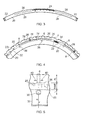
Figure 1 is an axial view of a shape adjusting tool; -
Figure 2 is a partial perspective view of the tool ofFigure 1 ; -
Figure 3 shows a segment of an adjustment ring of the tool ofFigures 1 and 2 ; -
Figure 4 shows part of the tool; and -
Figure 5 is an enlarged view of part of the tool as shown inFigure 4 . - With reference to
Figures 1 and 2 , the tool comprises abase structure 2 comprising a supportingplate 4. The supportingplate 4 carries an array ofadjuster elements 6 or plungers and anadjustment ring 8. The supportingplate 4 has a double-layered structure, comprising abase plate 10 andguide plates 12 which guide movement of theadjuster elements 6 and theadjustment ring 8 and which define the spacing between thebase plate 10 and acover plate 18. A circumferentialinner web 14 andradial webs 16 are secured to the supportingplate 4 to enhance its rigidity. As shown inFigure 1 ,cover plates 18 are secured over the supportingplate 4 to retain theadjuster elements 6 and theadjustment ring 8. The cover plate is provided with a series of cut-outs, or windows, which permits visual access to portions of the adjustment ring when the cover plate is in position. Thecover plates 18 are not shown inFigures 2 to 5 . - The
adjustment ring 8 comprises sixidentical segments 20, one of which is shown inFigure 3 . Eachsegment 20 has anundercut notch 22 at each end and subtends an angle between its ends of slightly less than 30 degrees. In its central region, thesegment 20 is fitted with a circumferentially extendingtoothed rack 24. On each side of therack 24 there is aramp surface 26. Thus, the radial thickness of thesegment 20 increases from the left-hand of eachramp 26 towards the right-hand end, as viewed inFigure 3 . Ascale 28 is provided along eachramp surface 26, and part of eachscale 28 is visible through awindow 30 in the respective cover plate 18 (seeFigure 1 ). -
Figure 4 shows, at least in part, three of thesegments 20 mounted on the supportingplate 4. The middle one of thesegments 20 is connected to the one to its left by arigid link 32 which engages therespective notches 22 in thesegments 20. Themiddle segment 20 is connected to thesegment 20 on its right by aresilient link 34, which also engages therespective notches 22. Apart from the singleresilient link 34 shown inFigure 4 , all of the other junctions betweenadjacent segments 20 are made by way ofrigid links 32. - The
adjustment ring 8 is supported for rotation on the supportingplate 4 by means of fixed-axis bearingrollers 36 which are distributed regularly around the supportingplate 4. Eachsegment 20 is supported by tworollers 36, and theresilient link 34 enables the circumferential length of theadjustment ring 8 to vary slightly in order to ensure that theadjustment ring 8 as a whole is in contact with each one of therollers 36. - The supporting
plate 4 also carries arespective pinion 38 for therack 24 of eachsegment 20. Eachpinion 38 has a square, or otherwise non-circular, opening for receiving a drive tool. - In the position shown in
Figure 4 , theadjustment ring 8 is positioned so that the left-hand end of therack 24 engages thepinion 38. Similarly, eachadjuster element 6 is situated at the left-hand end of therespective ramp surface 26. This is the lower end of theramp surface 26, and so eachadjuster element 6 is fully retracted in the radial inwards direction under the action of resilient limbs 40 (Figure 5 ). Rotation by a suitable tool of any one of thepinions 38 in the clockwise direction will cause counter clockwise rotation of theadjustment ring 8, so displacing theramp surfaces 26 to the left (as seen inFigure 4 ), so causing theadjuster elements 6 to be displaced radially outwardly. The extent to which theadjuster elements 6 are displaced can be read from thescales 28 as visible through thewindows 30. - It will be appreciated that the
rollers 36 are at the same angular positions as theadjuster elements 6 around theadjustment ring 8. Consequently, forces applied to theadjuster elements 6 by the component to be corrected are transmitted through thesegments 20 directly to therollers 36, so causing no bending moment to be applied to thesegments 20. - The adjusting tool may be supported within the component to be corrected by any suitable means. By way of example, a
pivotable clip 42 is shown inFigure 2 , which can be swung into engagement with a flange at one end of the component in order to retain the tool in position. - It will be appreciated that, for operation, the tool is supported within the hollow component to be corrected or adjusted, for example by means of the
clips 42, so that the tool sits perpendicular to the axis of the hollow component. Thepinion 38 is then turned so as to displace theadjustment ring 8 to extend theadjuster elements 6 radially outwardly of thebase structure 2. Theramp surfaces 26 are identical to each other, and consequently theadjuster elements 6 move in unison such that their radially outer tips always lie on a common radius from the central axis of the tool, as indicated at X inFigure 1 . The tips of theadjuster elements 6 are profiled to contact the inside surface of the component to be adjusted. After contact with the component by at least some of theadjuster elements 6, the application of torque to therespective pinion 38 generates sufficient force at the tips of theadjuster elements 6 to deform the component to the desired shape, which would be circular in the embodiment described with reference to the drawings. The tool can thus be used to hold the component in the desired shape while further machining or other processing takes place on the component. - The slope of each
ramp 26, defined as radial displacement of the surface with respect to angular rotation of theadjustment ring 8, may be linear so that thescale 28 can represent the resulting displacement of theadjuster elements 6 from a nominal position in regular increments. - Because two
rollers 36 support eachsegment 20 and because the segments can pivot relatively to one another by way of therigid links 32 and theresilient link 34, it is possible to ensure that theindividual segments 20 remain in contact with both of therespective rollers 36 at all times. Eachsegment 20 can thus move over itsrollers 36 in a stable manner to ensure that radial displacement of theadjuster elements 6 is consistent and is replicated equally for all of theadjuster elements 6 of the tool. - The sheet metal components of the tool can be formed very accurately, for example by laser cutting, from sheets of an appropriate material, for example steel. It is consequently possible to manufacture the tool with very close tolerances so that accurate shape adjustment of hollow components can be achieved.
- Thus, with reference to
Figure 5 , the overall diameter of the tool, i.e. diametrically from tip to tip ofopposite elements 6 is: - Overall diameter = 2 x R + B + 2 x RAMP + 2 x PL, where
- R = Radius to the centre of the
rollers 36 - B = Diameter of
rollers 36 - RAMP = Radial width of the
segment 20 at theramp surface 26 - PL = The length of the
adjuster element 6 - As the tolerance achievable on the roller diameter B is very high this can be ignored. Therefore the overall tolerance is dependent upon 2 x (R + RAMP+ PL). The tolerance on the RAMP and PL is purely dependent upon the repeatability of the laser used to cut the parts and is therefore less than 10µm for each part.
- The radius R from the axis X to the centre of the mounting hole for the
roller 36, is therefore critical and requires that the laser cut position of the hole is controlled as tightly as possible. The resulting roundness tolerance for the plungers has been measured and seen to be consistently better than 0.1 mm. - By way of specific example, the
ramp surface 26 may have a radial difference between its ends of 0.6 mm over 110 mm giving a ramp of approximately 5µm/mm of circumferential displacement. As a result, any small amount of error in the circumferential positioning between the circular strips results in only a very small change in the diameter and is therefore virtually eliminated. - Because only a single
resilient link 34 is provided, thesegments 20 move as one once installed over therollers 36. Consequently, errors in displacement between theadjuster elements 6 are eliminated. - For hollow components having a relatively large axial length, it is possible to employ two or more stacked tools along the length of the component in order to ensure the required circularity of the component along its length.
- Although the embodiment described above comprises six
segments 20, each having twoadjuster elements 6, it will be appreciated that other numbers ofsegments 20 andadjuster elements 6 are possible. Also, it is possible for the tool to be modified to cause theadjuster elements 6 to engage the outer surface of the component to be adjusted.
Claims (15)
- A shape adjusting tool for adjusting the shape of a hollow component, the tool comprising a base structure carrying a plurality of adjuster elements which are distributed circumferentially about an axis of the tool, the tool also comprising an adjustment ring which is mounted on the base structure for rotation about the axis, a respective ramp arrangement being provided between each adjuster element and the adjustment ring whereby rotation of the adjustment ring about the axis causes radial displacement of each adjuster element.
- A shape adjusting tool as claimed in claim 1, in which the adjustment ring is resilient in the circumferential direction.
- A shape adjusting tool as claimed in claim 2, in which the adjustment ring includes a resilient element which is resilient in the circumferential direction of the adjustment ring.
- A shape adjusting tool as claimed in claim 3, in which the adjustment ring comprises a plurality of segments, the resilient element being disposed at one of the junctions between adjacent segments.
- A shape adjusting tool as claimed in claim 4, in which the other junctions between adjacent segments are rigid in the circumferential direction.
- A shape adjusting tool as claimed in any one of the preceding claims, in which each segment engages two of the adjuster elements through respective ramp arrangements.
- A shape adjusting tool as claimed in any one of claims 4 to 6, in which there are six of the segments.
- A shape adjusting tool as claimed in any one of the preceding claims, in which each ramp arrangement comprises a ramp surface on the adjustment ring which directly engages a respective one of the adjuster elements.
- A shape adjusting tool as claimed in claim 8, in which there is a linear relationship between the angular position of the adjustment ring and the radial position of each adjuster element.
- A shape adjusting tool as claimed in claim 9, in which the linear relationship is the same for all of the adjuster elements, whereby the adjuster elements move in unison upon rotation of the adjustment ring.
- A shape adjusting tool as claimed in any one of the preceding claims, in which the adjustment ring is supported on the base structure by circumferentially distributed bearing rollers.
- A shape adjusting tool as claimed in claim 11, in which the bearing rollers are disposed respectively at the same angular positions as the adjuster elements.
- A shape adjusting tool as claimed in claim 11 or 12, when appendant to claim 4, in which each segment is supported by two bearing rollers.
- A shape adjusting tool as claimed in any one of the preceding claims, in which the adjustment ring comprising a circumferentially extending toothed rack and the base structure comprises a pinion, whereby rotation of the pinion causes rotation of the adjustment ring.
- A shape adjusting tool as claimed in any one of the preceding claims, in which the ramp arrangement is disposed so as to drive the adjuster elements radially outwardly on rotation of the adjustment ring.
Applications Claiming Priority (1)
| Application Number | Priority Date | Filing Date | Title |
|---|---|---|---|
| GBGB1018756.5A GB201018756D0 (en) | 2010-11-08 | 2010-11-08 | A shape adjusting tool |
Publications (2)
| Publication Number | Publication Date |
|---|---|
| EP2450119A1 true EP2450119A1 (en) | 2012-05-09 |
| EP2450119B1 EP2450119B1 (en) | 2015-02-25 |
Family
ID=43414454
Family Applications (1)
| Application Number | Title | Priority Date | Filing Date |
|---|---|---|---|
| EP11185551.6A Active EP2450119B1 (en) | 2010-11-08 | 2011-10-18 | A shape adjusting tool |
Country Status (3)
| Country | Link |
|---|---|
| US (1) | US8474298B2 (en) |
| EP (1) | EP2450119B1 (en) |
| GB (1) | GB201018756D0 (en) |
Cited By (2)
| Publication number | Priority date | Publication date | Assignee | Title |
|---|---|---|---|---|
| FR3060438A1 (en) * | 2016-12-15 | 2018-06-22 | Safran Aircraft Engines | METHOD AND TOOLING FOR FORMING A BLOWER HOUSING |
| CN108928020A (en) * | 2017-05-27 | 2018-12-04 | 贺尔碧格(上海)有限公司 | A kind of nonmetallic ring circularity regulating device |
Families Citing this family (3)
| Publication number | Priority date | Publication date | Assignee | Title |
|---|---|---|---|---|
| CN104722609B (en) * | 2015-03-02 | 2017-06-16 | 共享铸钢有限公司 | A kind of devices and methods therefor for correcting c-type steel-casting |
| US9777600B2 (en) | 2015-06-04 | 2017-10-03 | General Electric Company | Installation apparatus and related methods for coupling flow sleeve and transition piece |
| CN114734279B (en) * | 2022-03-31 | 2024-03-01 | 江阴市博汇机械成套设备有限公司 | Thin-wall sleeve cylindricity error micro-digital correction clamp and correction method |
Citations (4)
| Publication number | Priority date | Publication date | Assignee | Title |
|---|---|---|---|---|
| GB1201435A (en) * | 1968-02-07 | 1970-08-05 | Ogden & Company Pipeline Const | A device for correcting out-of-roundness in pipes |
| US5203197A (en) * | 1991-08-19 | 1993-04-20 | Cogsdill Tool Products, Inc. | Clamp assembly |
| US5444902A (en) * | 1994-06-29 | 1995-08-29 | The United States Of America As Represented By The United States National Aeronautics And Space Administration | Cylinder rounding/holding tool |
| WO2000024546A1 (en) * | 1998-10-23 | 2000-05-04 | Proline Pipe Equipment Inc. | Internal backup ring system |
Family Cites Families (7)
| Publication number | Priority date | Publication date | Assignee | Title |
|---|---|---|---|---|
| US1823047A (en) * | 1926-12-08 | 1931-09-15 | American Can Co | Method of and apparatus for beading of formed sheet metal articles |
| US3109477A (en) * | 1962-09-25 | 1963-11-05 | Crose United Corp | Mandrel for pipe bending machines |
| FI791227A7 (en) | 1979-04-17 | 1981-01-01 | Jorma Lillbacka | Pressing device. |
| US4406151A (en) * | 1981-04-23 | 1983-09-27 | Amca International Corporation | Collapsible fixture for manufacture of tunnel tubes |
| US4778252A (en) | 1987-02-27 | 1988-10-18 | Newport Corporation | Self-centering holder for objects of various sizes |
| FR2755042B1 (en) * | 1996-10-24 | 1998-12-24 | Lemforder Nacam Sa | PROCESS FOR OBTAINING SPLINES ON A TREE |
| JP4866428B2 (en) * | 2006-12-18 | 2012-02-01 | 積水化学工業株式会社 | Pipe making apparatus and rehabilitation method of existing pipe using this pipe making apparatus |
-
2010
- 2010-11-08 GB GBGB1018756.5A patent/GB201018756D0/en not_active Ceased
-
2011
- 2011-10-18 EP EP11185551.6A patent/EP2450119B1/en active Active
- 2011-10-18 US US13/275,537 patent/US8474298B2/en active Active
Patent Citations (4)
| Publication number | Priority date | Publication date | Assignee | Title |
|---|---|---|---|---|
| GB1201435A (en) * | 1968-02-07 | 1970-08-05 | Ogden & Company Pipeline Const | A device for correcting out-of-roundness in pipes |
| US5203197A (en) * | 1991-08-19 | 1993-04-20 | Cogsdill Tool Products, Inc. | Clamp assembly |
| US5444902A (en) * | 1994-06-29 | 1995-08-29 | The United States Of America As Represented By The United States National Aeronautics And Space Administration | Cylinder rounding/holding tool |
| WO2000024546A1 (en) * | 1998-10-23 | 2000-05-04 | Proline Pipe Equipment Inc. | Internal backup ring system |
Cited By (4)
| Publication number | Priority date | Publication date | Assignee | Title |
|---|---|---|---|---|
| FR3060438A1 (en) * | 2016-12-15 | 2018-06-22 | Safran Aircraft Engines | METHOD AND TOOLING FOR FORMING A BLOWER HOUSING |
| US10759122B2 (en) | 2016-12-15 | 2020-09-01 | Safran Aircraft Engines | Method and tooling for shaping a fan casing |
| CN108928020A (en) * | 2017-05-27 | 2018-12-04 | 贺尔碧格(上海)有限公司 | A kind of nonmetallic ring circularity regulating device |
| CN108928020B (en) * | 2017-05-27 | 2024-05-07 | 贺尔碧格(上海)有限公司 | Non-metal ring roundness adjusting device |
Also Published As
| Publication number | Publication date |
|---|---|
| US8474298B2 (en) | 2013-07-02 |
| US20120111084A1 (en) | 2012-05-10 |
| GB201018756D0 (en) | 2010-12-22 |
| EP2450119B1 (en) | 2015-02-25 |
Similar Documents
| Publication | Publication Date | Title |
|---|---|---|
| US8474298B2 (en) | Shape adjusting tool | |
| CA2733807C (en) | Centering mandrel | |
| RU2557353C2 (en) | Tool for consecutive indexing of balancing check for rotor balancing check | |
| US20050252001A1 (en) | Method of manufacturing thin wall isogrid casings | |
| US8032998B2 (en) | Manufacturing apparatus for a foil bearing | |
| JP7759903B2 (en) | Hollow Encoder Calibration Device | |
| CN111185609A (en) | Aligning chuck and measurement compensation device applied to pipe cutting device | |
| US4059036A (en) | Shearing hollow stock | |
| US5263575A (en) | Drive sprocket systems for registration of spaced metal laminations across the width of plastic conveyor belts | |
| KR20140051114A (en) | Motion control apparatus | |
| WO2000067253A1 (en) | Method and apparatus for balancing a spindle in a hard disk drive | |
| EP3254791B1 (en) | Placement apparatus for shaft body inserts | |
| WO2004008076A1 (en) | Scale reading apparatus | |
| US20150252825A1 (en) | Support structure for radial application | |
| US20050235502A1 (en) | Rotary scale | |
| EA030873B1 (en) | Transmission gear, roller reducer comprising the transmission gear, and method of assembly thereof | |
| KR20230036608A (en) | Measuring method of inner diameter of needle bearing in CVVD manufacturing process | |
| CN215893475U (en) | Device based on radial measurement steel pipe external diameter | |
| CN112855858A (en) | Rotary driving device | |
| US20080272769A1 (en) | Pulse Generator Wheel, Preferably for Shafts, and Method for Manufacturing such a Pulse Generator Wheel | |
| CN111660281A (en) | Parallel robot assembling method and auxiliary tool thereof | |
| US20120000868A1 (en) | Ring supporting device | |
| US5666738A (en) | Calibration and measuring tool | |
| EP4253916A1 (en) | Method of mounting a rotary scale member | |
| WO2022171994A1 (en) | Rotary encoder |
Legal Events
| Date | Code | Title | Description |
|---|---|---|---|
| PUAI | Public reference made under article 153(3) epc to a published international application that has entered the european phase |
Free format text: ORIGINAL CODE: 0009012 |
|
| AK | Designated contracting states |
Kind code of ref document: A1 Designated state(s): AL AT BE BG CH CY CZ DE DK EE ES FI FR GB GR HR HU IE IS IT LI LT LU LV MC MK MT NL NO PL PT RO RS SE SI SK SM TR |
|
| AX | Request for extension of the european patent |
Extension state: BA ME |
|
| 17P | Request for examination filed |
Effective date: 20120919 |
|
| GRAP | Despatch of communication of intention to grant a patent |
Free format text: ORIGINAL CODE: EPIDOSNIGR1 |
|
| RIC1 | Information provided on ipc code assigned before grant |
Ipc: B21C 37/30 20060101ALI20141023BHEP Ipc: B21D 3/14 20060101AFI20141023BHEP Ipc: B29C 53/20 20060101ALI20141023BHEP |
|
| INTG | Intention to grant announced |
Effective date: 20141113 |
|
| GRAS | Grant fee paid |
Free format text: ORIGINAL CODE: EPIDOSNIGR3 |
|
| GRAA | (expected) grant |
Free format text: ORIGINAL CODE: 0009210 |
|
| AK | Designated contracting states |
Kind code of ref document: B1 Designated state(s): AL AT BE BG CH CY CZ DE DK EE ES FI FR GB GR HR HU IE IS IT LI LT LU LV MC MK MT NL NO PL PT RO RS SE SI SK SM TR |
|
| REG | Reference to a national code |
Ref country code: GB Ref legal event code: FG4D |
|
| REG | Reference to a national code |
Ref country code: CH Ref legal event code: EP |
|
| REG | Reference to a national code |
Ref country code: IE Ref legal event code: FG4D |
|
| REG | Reference to a national code |
Ref country code: DE Ref legal event code: R096 Ref document number: 602011013928 Country of ref document: DE Effective date: 20150409 |
|
| REG | Reference to a national code |
Ref country code: AT Ref legal event code: REF Ref document number: 711477 Country of ref document: AT Kind code of ref document: T Effective date: 20150415 |
|
| REG | Reference to a national code |
Ref country code: NL Ref legal event code: VDEP Effective date: 20150225 |
|
| REG | Reference to a national code |
Ref country code: AT Ref legal event code: MK05 Ref document number: 711477 Country of ref document: AT Kind code of ref document: T Effective date: 20150225 |
|
| REG | Reference to a national code |
Ref country code: LT Ref legal event code: MG4D |
|
| RAP2 | Party data changed (patent owner data changed or rights of a patent transferred) |
Owner name: ROLLS-ROYCE PLC |
|
| PG25 | Lapsed in a contracting state [announced via postgrant information from national office to epo] |
Ref country code: HR Free format text: LAPSE BECAUSE OF FAILURE TO SUBMIT A TRANSLATION OF THE DESCRIPTION OR TO PAY THE FEE WITHIN THE PRESCRIBED TIME-LIMIT Effective date: 20150225 Ref country code: SE Free format text: LAPSE BECAUSE OF FAILURE TO SUBMIT A TRANSLATION OF THE DESCRIPTION OR TO PAY THE FEE WITHIN THE PRESCRIBED TIME-LIMIT Effective date: 20150225 Ref country code: LT Free format text: LAPSE BECAUSE OF FAILURE TO SUBMIT A TRANSLATION OF THE DESCRIPTION OR TO PAY THE FEE WITHIN THE PRESCRIBED TIME-LIMIT Effective date: 20150225 Ref country code: ES Free format text: LAPSE BECAUSE OF FAILURE TO SUBMIT A TRANSLATION OF THE DESCRIPTION OR TO PAY THE FEE WITHIN THE PRESCRIBED TIME-LIMIT Effective date: 20150225 Ref country code: FI Free format text: LAPSE BECAUSE OF FAILURE TO SUBMIT A TRANSLATION OF THE DESCRIPTION OR TO PAY THE FEE WITHIN THE PRESCRIBED TIME-LIMIT Effective date: 20150225 Ref country code: NO Free format text: LAPSE BECAUSE OF FAILURE TO SUBMIT A TRANSLATION OF THE DESCRIPTION OR TO PAY THE FEE WITHIN THE PRESCRIBED TIME-LIMIT Effective date: 20150525 |
|
| PG25 | Lapsed in a contracting state [announced via postgrant information from national office to epo] |
Ref country code: AT Free format text: LAPSE BECAUSE OF FAILURE TO SUBMIT A TRANSLATION OF THE DESCRIPTION OR TO PAY THE FEE WITHIN THE PRESCRIBED TIME-LIMIT Effective date: 20150225 Ref country code: LV Free format text: LAPSE BECAUSE OF FAILURE TO SUBMIT A TRANSLATION OF THE DESCRIPTION OR TO PAY THE FEE WITHIN THE PRESCRIBED TIME-LIMIT Effective date: 20150225 Ref country code: RS Free format text: LAPSE BECAUSE OF FAILURE TO SUBMIT A TRANSLATION OF THE DESCRIPTION OR TO PAY THE FEE WITHIN THE PRESCRIBED TIME-LIMIT Effective date: 20150225 Ref country code: IS Free format text: LAPSE BECAUSE OF FAILURE TO SUBMIT A TRANSLATION OF THE DESCRIPTION OR TO PAY THE FEE WITHIN THE PRESCRIBED TIME-LIMIT Effective date: 20150625 Ref country code: GR Free format text: LAPSE BECAUSE OF FAILURE TO SUBMIT A TRANSLATION OF THE DESCRIPTION OR TO PAY THE FEE WITHIN THE PRESCRIBED TIME-LIMIT Effective date: 20150526 |
|
| PG25 | Lapsed in a contracting state [announced via postgrant information from national office to epo] |
Ref country code: NL Free format text: LAPSE BECAUSE OF FAILURE TO SUBMIT A TRANSLATION OF THE DESCRIPTION OR TO PAY THE FEE WITHIN THE PRESCRIBED TIME-LIMIT Effective date: 20150225 |
|
| REG | Reference to a national code |
Ref country code: FR Ref legal event code: PLFP Year of fee payment: 5 |
|
| PG25 | Lapsed in a contracting state [announced via postgrant information from national office to epo] |
Ref country code: DK Free format text: LAPSE BECAUSE OF FAILURE TO SUBMIT A TRANSLATION OF THE DESCRIPTION OR TO PAY THE FEE WITHIN THE PRESCRIBED TIME-LIMIT Effective date: 20150225 Ref country code: SK Free format text: LAPSE BECAUSE OF FAILURE TO SUBMIT A TRANSLATION OF THE DESCRIPTION OR TO PAY THE FEE WITHIN THE PRESCRIBED TIME-LIMIT Effective date: 20150225 Ref country code: CZ Free format text: LAPSE BECAUSE OF FAILURE TO SUBMIT A TRANSLATION OF THE DESCRIPTION OR TO PAY THE FEE WITHIN THE PRESCRIBED TIME-LIMIT Effective date: 20150225 Ref country code: EE Free format text: LAPSE BECAUSE OF FAILURE TO SUBMIT A TRANSLATION OF THE DESCRIPTION OR TO PAY THE FEE WITHIN THE PRESCRIBED TIME-LIMIT Effective date: 20150225 Ref country code: RO Free format text: LAPSE BECAUSE OF FAILURE TO SUBMIT A TRANSLATION OF THE DESCRIPTION OR TO PAY THE FEE WITHIN THE PRESCRIBED TIME-LIMIT Effective date: 20150225 |
|
| REG | Reference to a national code |
Ref country code: DE Ref legal event code: R097 Ref document number: 602011013928 Country of ref document: DE |
|
| PG25 | Lapsed in a contracting state [announced via postgrant information from national office to epo] |
Ref country code: PL Free format text: LAPSE BECAUSE OF FAILURE TO SUBMIT A TRANSLATION OF THE DESCRIPTION OR TO PAY THE FEE WITHIN THE PRESCRIBED TIME-LIMIT Effective date: 20150225 |
|
| PG25 | Lapsed in a contracting state [announced via postgrant information from national office to epo] |
Ref country code: IT Free format text: LAPSE BECAUSE OF FAILURE TO SUBMIT A TRANSLATION OF THE DESCRIPTION OR TO PAY THE FEE WITHIN THE PRESCRIBED TIME-LIMIT Effective date: 20150225 |
|
| PLBE | No opposition filed within time limit |
Free format text: ORIGINAL CODE: 0009261 |
|
| STAA | Information on the status of an ep patent application or granted ep patent |
Free format text: STATUS: NO OPPOSITION FILED WITHIN TIME LIMIT |
|
| 26N | No opposition filed |
Effective date: 20151126 |
|
| PG25 | Lapsed in a contracting state [announced via postgrant information from national office to epo] |
Ref country code: SI Free format text: LAPSE BECAUSE OF FAILURE TO SUBMIT A TRANSLATION OF THE DESCRIPTION OR TO PAY THE FEE WITHIN THE PRESCRIBED TIME-LIMIT Effective date: 20150225 |
|
| REG | Reference to a national code |
Ref country code: DE Ref legal event code: R082 Ref document number: 602011013928 Country of ref document: DE Representative=s name: HERNANDEZ, YORCK, DIPL.-ING., DE |
|
| PG25 | Lapsed in a contracting state [announced via postgrant information from national office to epo] |
Ref country code: BE Free format text: LAPSE BECAUSE OF FAILURE TO SUBMIT A TRANSLATION OF THE DESCRIPTION OR TO PAY THE FEE WITHIN THE PRESCRIBED TIME-LIMIT Effective date: 20150225 Ref country code: LU Free format text: LAPSE BECAUSE OF FAILURE TO SUBMIT A TRANSLATION OF THE DESCRIPTION OR TO PAY THE FEE WITHIN THE PRESCRIBED TIME-LIMIT Effective date: 20151018 |
|
| REG | Reference to a national code |
Ref country code: CH Ref legal event code: PL |
|
| PG25 | Lapsed in a contracting state [announced via postgrant information from national office to epo] |
Ref country code: MC Free format text: LAPSE BECAUSE OF FAILURE TO SUBMIT A TRANSLATION OF THE DESCRIPTION OR TO PAY THE FEE WITHIN THE PRESCRIBED TIME-LIMIT Effective date: 20150225 |
|
| REG | Reference to a national code |
Ref country code: IE Ref legal event code: MM4A |
|
| PG25 | Lapsed in a contracting state [announced via postgrant information from national office to epo] |
Ref country code: CH Free format text: LAPSE BECAUSE OF NON-PAYMENT OF DUE FEES Effective date: 20151031 Ref country code: LI Free format text: LAPSE BECAUSE OF NON-PAYMENT OF DUE FEES Effective date: 20151031 |
|
| REG | Reference to a national code |
Ref country code: FR Ref legal event code: PLFP Year of fee payment: 6 |
|
| PG25 | Lapsed in a contracting state [announced via postgrant information from national office to epo] |
Ref country code: IE Free format text: LAPSE BECAUSE OF NON-PAYMENT OF DUE FEES Effective date: 20151018 |
|
| PG25 | Lapsed in a contracting state [announced via postgrant information from national office to epo] |
Ref country code: SM Free format text: LAPSE BECAUSE OF FAILURE TO SUBMIT A TRANSLATION OF THE DESCRIPTION OR TO PAY THE FEE WITHIN THE PRESCRIBED TIME-LIMIT Effective date: 20150225 Ref country code: BG Free format text: LAPSE BECAUSE OF FAILURE TO SUBMIT A TRANSLATION OF THE DESCRIPTION OR TO PAY THE FEE WITHIN THE PRESCRIBED TIME-LIMIT Effective date: 20150225 Ref country code: HU Free format text: LAPSE BECAUSE OF FAILURE TO SUBMIT A TRANSLATION OF THE DESCRIPTION OR TO PAY THE FEE WITHIN THE PRESCRIBED TIME-LIMIT; INVALID AB INITIO Effective date: 20111018 |
|
| PG25 | Lapsed in a contracting state [announced via postgrant information from national office to epo] |
Ref country code: CY Free format text: LAPSE BECAUSE OF FAILURE TO SUBMIT A TRANSLATION OF THE DESCRIPTION OR TO PAY THE FEE WITHIN THE PRESCRIBED TIME-LIMIT Effective date: 20150225 |
|
| PG25 | Lapsed in a contracting state [announced via postgrant information from national office to epo] |
Ref country code: MT Free format text: LAPSE BECAUSE OF FAILURE TO SUBMIT A TRANSLATION OF THE DESCRIPTION OR TO PAY THE FEE WITHIN THE PRESCRIBED TIME-LIMIT Effective date: 20150225 Ref country code: TR Free format text: LAPSE BECAUSE OF FAILURE TO SUBMIT A TRANSLATION OF THE DESCRIPTION OR TO PAY THE FEE WITHIN THE PRESCRIBED TIME-LIMIT Effective date: 20150225 |
|
| REG | Reference to a national code |
Ref country code: FR Ref legal event code: PLFP Year of fee payment: 7 |
|
| PG25 | Lapsed in a contracting state [announced via postgrant information from national office to epo] |
Ref country code: MK Free format text: LAPSE BECAUSE OF FAILURE TO SUBMIT A TRANSLATION OF THE DESCRIPTION OR TO PAY THE FEE WITHIN THE PRESCRIBED TIME-LIMIT Effective date: 20150225 Ref country code: PT Free format text: LAPSE BECAUSE OF FAILURE TO SUBMIT A TRANSLATION OF THE DESCRIPTION OR TO PAY THE FEE WITHIN THE PRESCRIBED TIME-LIMIT Effective date: 20150225 |
|
| REG | Reference to a national code |
Ref country code: FR Ref legal event code: PLFP Year of fee payment: 8 |
|
| PG25 | Lapsed in a contracting state [announced via postgrant information from national office to epo] |
Ref country code: AL Free format text: LAPSE BECAUSE OF FAILURE TO SUBMIT A TRANSLATION OF THE DESCRIPTION OR TO PAY THE FEE WITHIN THE PRESCRIBED TIME-LIMIT Effective date: 20150225 |
|
| P01 | Opt-out of the competence of the unified patent court (upc) registered |
Effective date: 20230528 |
|
| PGFP | Annual fee paid to national office [announced via postgrant information from national office to epo] |
Ref country code: DE Payment date: 20251028 Year of fee payment: 15 |
|
| PGFP | Annual fee paid to national office [announced via postgrant information from national office to epo] |
Ref country code: GB Payment date: 20251023 Year of fee payment: 15 |
|
| PGFP | Annual fee paid to national office [announced via postgrant information from national office to epo] |
Ref country code: FR Payment date: 20251027 Year of fee payment: 15 |