EP2450011A1 - Method for producing bodily fluid-absorbing pad and production device therefor - Google Patents
Method for producing bodily fluid-absorbing pad and production device therefor Download PDFInfo
- Publication number
- EP2450011A1 EP2450011A1 EP09846835A EP09846835A EP2450011A1 EP 2450011 A1 EP2450011 A1 EP 2450011A1 EP 09846835 A EP09846835 A EP 09846835A EP 09846835 A EP09846835 A EP 09846835A EP 2450011 A1 EP2450011 A1 EP 2450011A1
- Authority
- EP
- European Patent Office
- Prior art keywords
- bodily fluid
- fluid absorbent
- paired
- row
- rolls
- Prior art date
- Legal status (The legal status is an assumption and is not a legal conclusion. Google has not performed a legal analysis and makes no representation as to the accuracy of the status listed.)
- Withdrawn
Links
Images






Classifications
-
- A—HUMAN NECESSITIES
- A61—MEDICAL OR VETERINARY SCIENCE; HYGIENE
- A61F—FILTERS IMPLANTABLE INTO BLOOD VESSELS; PROSTHESES; DEVICES PROVIDING PATENCY TO, OR PREVENTING COLLAPSING OF, TUBULAR STRUCTURES OF THE BODY, e.g. STENTS; ORTHOPAEDIC, NURSING OR CONTRACEPTIVE DEVICES; FOMENTATION; TREATMENT OR PROTECTION OF EYES OR EARS; BANDAGES, DRESSINGS OR ABSORBENT PADS; FIRST-AID KITS
- A61F13/00—Bandages or dressings; Absorbent pads
- A61F13/15—Absorbent pads, e.g. sanitary towels, swabs or tampons for external or internal application to the body; Supporting or fastening means therefor; Tampon applicators
- A61F13/15577—Apparatus or processes for manufacturing
- A61F13/15707—Mechanical treatment, e.g. notching, twisting, compressing, shaping
- A61F13/15731—Treating webs, e.g. for giving them a fibrelike appearance, e.g. by embossing
-
- A—HUMAN NECESSITIES
- A61—MEDICAL OR VETERINARY SCIENCE; HYGIENE
- A61F—FILTERS IMPLANTABLE INTO BLOOD VESSELS; PROSTHESES; DEVICES PROVIDING PATENCY TO, OR PREVENTING COLLAPSING OF, TUBULAR STRUCTURES OF THE BODY, e.g. STENTS; ORTHOPAEDIC, NURSING OR CONTRACEPTIVE DEVICES; FOMENTATION; TREATMENT OR PROTECTION OF EYES OR EARS; BANDAGES, DRESSINGS OR ABSORBENT PADS; FIRST-AID KITS
- A61F13/00—Bandages or dressings; Absorbent pads
- A61F13/15—Absorbent pads, e.g. sanitary towels, swabs or tampons for external or internal application to the body; Supporting or fastening means therefor; Tampon applicators
- A61F13/15577—Apparatus or processes for manufacturing
- A61F13/15699—Forming webs by bringing together several webs, e.g. by laminating or folding several webs, with or without additional treatment of the webs
-
- A—HUMAN NECESSITIES
- A61—MEDICAL OR VETERINARY SCIENCE; HYGIENE
- A61F—FILTERS IMPLANTABLE INTO BLOOD VESSELS; PROSTHESES; DEVICES PROVIDING PATENCY TO, OR PREVENTING COLLAPSING OF, TUBULAR STRUCTURES OF THE BODY, e.g. STENTS; ORTHOPAEDIC, NURSING OR CONTRACEPTIVE DEVICES; FOMENTATION; TREATMENT OR PROTECTION OF EYES OR EARS; BANDAGES, DRESSINGS OR ABSORBENT PADS; FIRST-AID KITS
- A61F13/00—Bandages or dressings; Absorbent pads
- A61F13/15—Absorbent pads, e.g. sanitary towels, swabs or tampons for external or internal application to the body; Supporting or fastening means therefor; Tampon applicators
- A61F13/15577—Apparatus or processes for manufacturing
- A61F13/15707—Mechanical treatment, e.g. notching, twisting, compressing, shaping
- A61F13/15723—Partitioning batts; Cutting
-
- A—HUMAN NECESSITIES
- A61—MEDICAL OR VETERINARY SCIENCE; HYGIENE
- A61F—FILTERS IMPLANTABLE INTO BLOOD VESSELS; PROSTHESES; DEVICES PROVIDING PATENCY TO, OR PREVENTING COLLAPSING OF, TUBULAR STRUCTURES OF THE BODY, e.g. STENTS; ORTHOPAEDIC, NURSING OR CONTRACEPTIVE DEVICES; FOMENTATION; TREATMENT OR PROTECTION OF EYES OR EARS; BANDAGES, DRESSINGS OR ABSORBENT PADS; FIRST-AID KITS
- A61F13/00—Bandages or dressings; Absorbent pads
- A61F13/15—Absorbent pads, e.g. sanitary towels, swabs or tampons for external or internal application to the body; Supporting or fastening means therefor; Tampon applicators
- A61F13/45—Absorbent pads, e.g. sanitary towels, swabs or tampons for external or internal application to the body; Supporting or fastening means therefor; Tampon applicators characterised by the shape
- A61F13/47—Sanitary towels, incontinence pads or napkins
- A61F13/475—Sanitary towels, incontinence pads or napkins characterised by edge leakage prevention means
- A61F13/4751—Sanitary towels, incontinence pads or napkins characterised by edge leakage prevention means the means preventing fluid flow in a transversal direction
- A61F13/4756—Sanitary towels, incontinence pads or napkins characterised by edge leakage prevention means the means preventing fluid flow in a transversal direction the means consisting of grooves, e.g. channels, depressions or embossments, resulting in a heterogeneous surface level
-
- Y—GENERAL TAGGING OF NEW TECHNOLOGICAL DEVELOPMENTS; GENERAL TAGGING OF CROSS-SECTIONAL TECHNOLOGIES SPANNING OVER SEVERAL SECTIONS OF THE IPC; TECHNICAL SUBJECTS COVERED BY FORMER USPC CROSS-REFERENCE ART COLLECTIONS [XRACs] AND DIGESTS
- Y10—TECHNICAL SUBJECTS COVERED BY FORMER USPC
- Y10T—TECHNICAL SUBJECTS COVERED BY FORMER US CLASSIFICATION
- Y10T156/00—Adhesive bonding and miscellaneous chemical manufacture
- Y10T156/12—Surface bonding means and/or assembly means with cutting, punching, piercing, severing or tearing
-
- Y—GENERAL TAGGING OF NEW TECHNOLOGICAL DEVELOPMENTS; GENERAL TAGGING OF CROSS-SECTIONAL TECHNOLOGIES SPANNING OVER SEVERAL SECTIONS OF THE IPC; TECHNICAL SUBJECTS COVERED BY FORMER USPC CROSS-REFERENCE ART COLLECTIONS [XRACs] AND DIGESTS
- Y10—TECHNICAL SUBJECTS COVERED BY FORMER USPC
- Y10T—TECHNICAL SUBJECTS COVERED BY FORMER US CLASSIFICATION
- Y10T83/00—Cutting
- Y10T83/04—Processes
- Y10T83/0405—With preparatory or simultaneous ancillary treatment of work
- Y10T83/0419—By distorting within elastic limit
- Y10T83/0429—By compressing
-
- Y—GENERAL TAGGING OF NEW TECHNOLOGICAL DEVELOPMENTS; GENERAL TAGGING OF CROSS-SECTIONAL TECHNOLOGIES SPANNING OVER SEVERAL SECTIONS OF THE IPC; TECHNICAL SUBJECTS COVERED BY FORMER USPC CROSS-REFERENCE ART COLLECTIONS [XRACs] AND DIGESTS
- Y10—TECHNICAL SUBJECTS COVERED BY FORMER USPC
- Y10T—TECHNICAL SUBJECTS COVERED BY FORMER US CLASSIFICATION
- Y10T83/00—Cutting
- Y10T83/343—With means to deform work temporarily
Definitions
- the present invention relates to methods and apparatuses to make bodily fluid absorbent pads suitable to use in the form of various articles such as panty liners and sanitary napkins.
- Bodily fluid absorbent pad such as panty liners are well known. Such pads shaped to be symmetric with respect to a longitudinal center line as well as a transverse center line are also well known.
- an absorbent article disclosed in PTL 1 is shaped to be symmetric with respect to a longitudinal center line as well as a transverse center line and comprises a pair of absorbent article components being same in shape as well as in size put flat together in a thickness direction and partially compressed under heating so as to be detachably attached to each other along compressed lines.
- the upper absorbent article component When the upper absorbent article component has been contacted with a wearer's skin and soiled with bodily fluids, the upper absorbent article component may be peeled off from the lower absorbent article component and in turn, this lower one may be contacted with the wearer's skin.
- Each of the absorbent articles has a dimension in the transverse direction or the width of the article is larger in end regions opposite in the longitudinal direction than in an intermediate region defined between the end regions.
- the compressed lines along which the upper and lower absorbent article components are attached together extend in the longitudinal direction along the side edges of the article.
- the individual absorbent article components line up sideways and each pair of the adjacent absorbent article components leaves therebetween a relatively large space since the width of the absorbent article component is larger in the opposite end regions than in the intermediate region.
- the step of cutting out the individual absorbent article components inevitably generates scrap in large quantity.
- a fibrous web having a thickness in a range of 0.5 to 2 mm is used as the web formed with compressed lines, the depth and the appearance of the compressed lines might become uneven depending on the individual absorbent article components.
- the present invention intends to solve such problems occurring in the course of making the bodily fluid absorbent pad.
- the present invention includes a first aspect relating to a method for making a bodily fluid absorbent pad and a second aspect relating to an apparatus for making such bodily fluid absorbent pad.
- a method for making a bodily fluid absorbent pad the pad having a longitudinal direction, a transverse direction and a thickness direction being orthogonal one to another and shaped so as to be relatively long in the longitudinal direction, wherein the pad having a skin-contact surface and a skin-noncontact surface being an opposite surface of the skin-contact surface as viewed in the thickness direction, and a dimension in the transverse direction being larger in first and second end regions opposite to each other in the longitudinal direction than in an intermediate region extending between the first and second end regions, and wherein the pad is formed on the skin-contact surface with compressed lines extending in the longitudinal direction inside respective side edges extending in parallel with each other in the longitudinal direction thereof.
- the present invention on the first aspect thereof includes the steps as follow: feeding a bodily fluid absorbent web in a machine direction through paired compression rolls to partially compress the bodily fluid absorbent web and thereby to form the compressed lines including first and second compressed segments in the first and second end regions, respectively, and third compressed segments extending in the intermediate region, wherein compressing units for forming the compressed lines are provided on and projecting from a peripheral surface of at least one roll constituting the paired compression rolls and the compressing units are adapted to form one row extending in a circumferential direction and also wherein at least one additional row of the compressing units which is adjacent to and in parallel with the one row is provided in an axial direction of the one roll; and wherein there is an offset in the circumferential direction between the compressing units in the one row and the compressing unit in the one additional row so that the first and second compressed segments formed by the compressing units in the one row are lateral to the third compressed segment formed by the compressing unit in the one additional row, respectively; and making two or more rows of the bodily fluid absorb
- the method further includes a step of feeding a bodily fluid absorbent web through paired cutter rolls provided on downstream of the paired compression rolls in the machine direction to cut out the bodily fluid absorbent pads from the bodily fluid absorbent web having passed through the paired compression rolls wherein knife edges are provided on a peripheral surface of one cutter roll constituting the paired cutter rolls and arranged in an arrangement corresponding to an arrangement of the compressing units provided on said one compression roll constituting the paired compression rolls in the circumferential direction as well as in the axial direction.
- the method further includes, between the step of feeding the bodily fluid absorbent web through the paired compression rolls and the step of feeding the bodily fluid absorbent web through the paired cutter rolls, a step of permanently attaching bodily fluid impervious web defining the skin-noncontact surface in the bodily fluid absorbent pad to the bodily fluid absorbent web.
- the method further includes before the step of feeding the bodily fluid absorbent web through the paired compression rolls, a step of placing a second bodily fluid absorbent web upon a skin-contact surface of the bodily fluid absorbent web destined to be the skin-contact surface of the bodily fluid absorbent pad and then separably attaching the bodily fluid absorbent web and the second bodily fluid absorbent web to each other to make bodily fluid absorbent composite pads comprising the bodily fluid absorbent pads.
- the method further characterized in that at least one compression roll constituting the paired compression rolls is formed so as to receive a rod heater inserted thereinto wherein said rod heater is designed so that a watt density is higher at end regions thereof opposite to each other in the axial direction than in an intermediate region thereof extending between the end regions thereof.
- an apparatus for implementation of the method for making the bodily fluid absorbent pad there is provided an apparatus for implementation of the method for making the bodily fluid absorbent pad.
- one compression roll constituting the paired compression rolls adapted to compress the bodily fluid absorbent web has the compressing units projecting from the peripheral surface thereof and arranged in one row extending in a circumferential direction and also arranged in at least one additional row of said compressing units adjacent in an axial direction and extending in parallel with the one row of compressing units and there is an offset in the circumferential direction between the compressing unit in the one row and the compressing unit in the one additional row; and a third region in the one row adapted to form the third compressed segments are lateral to first and second regions in the additional row adapted to form the first and second compressed segments and opposed to each other in the circumferential direction.
- paired cutter rolls used to cut out the bodily fluid absorbent pads from the bodily fluid absorbent web is provided on downstream of the paired compression rolls in the machine direction and one cutter roll constituting the paired cutter rolls is provided on a peripheral surface thereof with knife edges in an arrangement corresponding to an arrangement of the compressing units on the one compression roll constituting the paired compression rolls in the circumferential direction as well as in the axial direction wherein the knife edges project from the peripheral surface of the one cutter roll constituting the paired cutter rolls and the other cutter roll of the paired cutter rolls has a smooth peripheral surface.
- compressing units are provided on and projected from the peripheral surface of the other one compression roll constituting the paired compression rolls and cooperate with the compressing units on the one compression roll constituting the paired compression rolls to compress the bodily fluid absorbent web.
- the peripheral surface of the one compression roll constituting the paired compression rolls includes regions each surrounded by the third region and the first and second regions opposed to each other in the circumferential direction, and each of these surrounded regions is formed with a small projection adapted to form an additional compressed line appearing in the bodily fluid absorbent web but not in the bodily fluid absorbent pad.
- the compressing units formed on the paired compression rolls adapted to act on the web running in the machine direction are set in array so as to form two or more rows in the machine direction and, in each pair of the rows being adjacent in the cross direction, the regions of the compressing units in one row adapted to form in the end regions of the pad with the compressed end segments are lateral to the regions of the compressing units in the adjacent row adapted to form in the intermediate region of the pad with the compressed intermediate segments.
- the individual pads can be cut out from such web with scrap as reduced as possible. Furthermore, there is no risk that the area over which the paired compression rolls used to form the pads with the compressed lines come in contact with the web might be abruptly changed and thereby might damage the web and/or the paired compression rolls.
- panty liner as a typical embodiment of the bodily fluid absorbent pad made by a method and an apparatus according to the present invention.
- Fig. 1 is a partially cutaway perspective view of a panty liner 10.
- a panty liner 10 has a longitudinal direction P, a transverse direction Q and a thickness direction R which are orthogonal one to another, and is symmetrically shaped with respect to the center line M bisecting the dimension thereof in the transverse direction Q as well as the center line N bisecting the dimension thereof in the longitudinal direction P.
- the liner 10 is contoured by a pair of side edges 11a, 11b extending in parallel with each other in the longitudinal direction P and a pair of end edges 11c, 11d extending in the transverse direction Q wherein these end edges 11c, 11d are connected to the side edges 11a, 11b, respectively.
- the liner 10 is shaped so as to be relatively long in the longitudinal direction P.
- the liner 10 is relatively wide in opposite end regions 31, 32 and zones having the maximum width A 1 are included in these end regions 31, 32.
- an intermediate region 33 extending between the end regions 31, 32 is narrower than the end regions 31, 32 and includes a zone having the minimum width B 1 .
- the end edges 11c, 11d describe curved lines which are convex outwardly of the liner 10 and, in the intermediate region 33, the side edges 11a, 11b describe curved lines which are convex inwardly of the liner 10.
- the liner 10 further includes a top-sheet 40, first and second intermediate sheets 41, 42, a back-sheet 43 and a release paper 44 so that a pressure-sensitive adhesive (not shown) coated on the back-sheet 43 can be exposed as the release paper 44 is peeled off from the back-sheet 43.
- the liner 10 is formed along the side edge 11a thereof with a first compressed line 21 and along the side edge 11b thereof with a second compressed line 22 which is symmetric with the first compressed line 21 in the transverse direction Q.
- Both the first compressed line 21 and the second compressed line 22 are assemblies comprising a plurality of small compressed spots 20 arranged in the longitudinal direction P so as to be spaced apart one from another and to define respective queues extending into the opposite end regions 31, 32 of the liner 10.
- the first compressed line 21 and the second compressed line 22 are spaced from each other by a dimension W as measured in the transverse direction Q.
- the first compressed line 21 includes compressed end segments 21c, 21d in the respective end regions 31, 32, and a compressed intermediate segment 21e in the intermediate region 33 between the compressed end segments 21c, 21d.
- the second compressed line 22 includes compressed end segments 22c, 22d and a compressed intermediate segment 22e.
- the top-sheet 40 and the first and second intermediate sheets 41, 42 put flat together to form a bodily fluid absorbent structure of the liner 10 are locally compressed by the paired compression rolls with or without heating to obtain the small compressed spots 20.
- materials respectively forming these sheets 40, 41, 42 are mechanically entangled one with another to prevent peel-off of these sheets 40, 41, 42 occurring in vicinities of the side edges 11a, 11b and, at the same time, to provide the liner 10 with a decorative effect.
- Such liner 10 has basically a laminated structure comprising the bodily fluid pervious top-sheet 40 made of a non-woven fabric containing thermoplastic synthetic fibers or a perforated plastic film, the first and second intermediate sheets 41, 42 which are bodily fluid absorbent and made of a non-woven fabric containing thermoplastic synthetic fibers and the back-sheet 43 made of a plastic film or a non-woven fabric containing thermoplastic synthetic fibers.
- thermoplastic synthetic fibers contained in the bodily fluid absorbing/containing layer are preferably modified to become hydrophilic. This layer may contain liquid-absorbent fibers such as pulp fibers.
- the top-sheet 40 defines the skin-contact surface of the liner 10 and the back-sheet 43 defines the skin-noncontact surface of the liner 10 opposed to the skin-contact surface, i.e., the garment-contact surface 43a adapted to be put in contact with the wearer's garment (not shown).
- This garment-contact surface 43a is coated with pressure-sensitive adhesive (not shown) which is, in turn, protectively covered with a separator 44.
- the exemplarily illustrated liner 10 is shaped to be symmetric with respect to the center line M as well as the center line N so that the liner 10 can be properly put on the wearer's body whether the end 11c is in front or the end 11d is in front.
- Fig. 2 exemplarily and schematically illustrates a process of making the liner 10.
- the process includes a first section A to obtain the bodily fluid absorbent layer of the liner 10, a second section B to obtain the bodily fluid impervious layer after the bodily fluid absorbent layer has been formed with the first and second compressed lines 21, 22, and a third section C following the second section B.
- the first section A includes a first step 105 through a third step 107. Specifically, in the first step 105, a first web 124 from which the top-sheet 40 will be obtained and a second web 125 from which the first intermediate sheet 41 will be obtained are fed from the right hand as viewed in Fig. 2 in a machine direction MD. Also in the first step 105, a coater 204 is used to coat one surface of the second web 125 with hot melt adhesive (not shown).
- the first and second webs 124, 125 are fed to paired rolls 209 and attached to each other by hot melt adhesive coated on the second web 125 to obtain a first laminated web 114.
- a third web 126 from which the second intermediate sheet 42 will be obtained is fed in the machine direction MD and, in the course of feeding this third web 126, a coater 212 is used to coat one surface of the third web 126 with hot melt adhesive (not shown). Also in the third step 107, paired rolls 213 rotating in the machine direction MD is used to attach the first laminated web 114 to the third web 126 having been coated with hot melt adhesive and thereby to obtain a second laminated web 115.
- the second section B includes a fourth step 108 and a fifth step 110.
- the fourth step 108 the second laminated web 115 being kept by a tension controller 301 under a predetermined tension in the machine direction MD is fed to paired compression rolls 302 consisting of a first roll 302a and a second roll 302b.
- the first roll 302a is formed on its peripheral surface with projections 351 (See Figs. 3 and 4 ) corresponding to the respective small compressed spots 20 (See Fig. 1 ) while the second roll 302b is formed on its peripheral surface with anvil-mode projections 361 (See Figs. 5 and 6 ) opposed to the associated projections 351.
- regions of the second laminated web 115 in which the first compressed line 21 and the second compressed line 22 will be formed are compressed so that at least the first, second and third webs 124, 125, 126 constituting the second laminated web 115 may be mechanically entangled together. In this way, a first composite web 116 is obtained.
- a coater 303 is used to coat the third web 126 constituting the first composite web 116 with hot melt adhesive (not shown).
- a fourth web 127, a bodily fluid impervious web from which the back-sheet 43 of the liner 10 will be obtained and a fifth web 128 from which the separator 47 of the liner 10 will be obtained are fed in the machine direction MD.
- a coater 306 is used to coat one surface of the fifth web 128 with hot melt adhesive (not shown).
- the fourth web 127 and the fifth web 128 are fed to paired rolls 318 to attach these fourth and fifth webs 127, 128 to each other by adhesive previously coated on the fifth web 128.
- the fourth web 127 is put flat upon the third web 126 of the first composite web 116 previously coated with adhesive by the coater 303.
- the fourth web 127, the fifth web 128 and the first composite web 116 are fed so as to pass through paired rolls 319 and to be attached together. In this way, a second composite web 117 is obtained.
- the second composite web 117 is continuously fed to paired cutter rolls 330 consisting of two rolls 331a, 331b rotating in the machine direction MD and thereby individual composites 350, i.e., the individual liners 10 as shown in Fig. 1 are successively cut out from the web 117.
- appropriate means such as paired conveyer rolls 321 or an endless belt 322 is used to convey the individual composites 350 in the machine direction MD and, in the course of conveying, these composites 350 are successively wrapped, for example, by the plastic film to obtain envelopes each containing therein the liner 10.
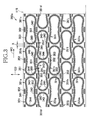
- Fig. 3 illustrates the peripheral surface of the first roll 302a constituting the paired compression rolls 302 used in the process illustrated in Fig. 2 as has been flatly developed and Fig. 4 is a sectional view taken along line IV-IV in Fig. 3 .
- the first roll 302a depicted in Fig. 3 is formed on the peripheral surface thereof with, in addition to a plurality of loop-shaped projections 351 adapted to form the first compressed line 21 and the second compressed line 22, a plurality of small projections 352 extending in the machine direction MD.
- These projections 351 and the small projections 352 have profiles as illustrated by Fig. 4 .
- each of the projections 351 is necessary and sufficient to form all compressed lines included in the individual liner 10 and, from the viewpoint of this, each of the projections 351 can be referred to as "compressing unit".
- projections 351 formed on the peripheral surface of the first roll 302a are arranged in five rows each extending to the machine direction MD wherein the first row includes the projections 351a, 351b and 351c; the second row includes the projections 351d, 351e and 351f; the third row includes the projections 351g, 351h and 351i; the fourth row includes the projections 351j, 351k and 351l; and the fifth row includes the projections 351m, 351n and 351o.
- projections 351a through 351o referred to herein generically as the projection 351 are the same in shape as well as in size and respectively include in addition to lateral projection segments 341, 342 having planar shapes corresponding to the compressed intermediate segments 21e, 22e in the first and second compressed lines 21, 22, end region projection segments 343, 344 extending between the lateral projection segments 341, 342 and adapted to form the compressed end segments 21c, 21d, 22c, 22d in the respective end regions 31, 32.
- each pair of projections 351 being adjacent in the machine direction MD may be spaced from each other by a dimension X.
- the end region projection segment 343 of the projection 351d and the end region projection segment 344 of the projection 351e in the second row are positioned adjacent the lateral projection segment 342 of the projection 351a in the first row as viewed in the cross direction CD.
- the offset is in the length of approximately by a half of the length of the projection 351.
- the first row includes the projections 351a - 351c as the projection 351 and the second row includes the projection 351d - 351f as the projection 351.
- the end region projection segment 343 of the projection 351d is opposed to the end region projection segment 344 of the projection 351e in the machine direction MD.
- the lateral projection segment 342 of the projection 351a in the first row, the end region projection segment 343 of the projection 351d and the end region projection segment 344 of the projection 351e surround a region 360 in which the small projection 352 is formed.
- Such small projection 352 has the same height as that of the projection 351.
- the second laminated web 115 fed to the paired compression rolls 302 is indicated by imaginary lines.
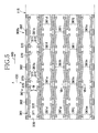
- Fig. 5 illustrates the peripheral surface of the second roll 302b constituting the paired compression rolls 302 as has been flatly developed and Fig. 6 is a sectional view taken along line VI-VI in Fig. 5 .
- the second laminated web 115 is indicated by imaginary lines.
- the second roll 302b provides anvils adapted to cooperate with the associated projections 351 on the first roll 302a and, more specifically, the second roll 302b is formed on its peripheral surface with anvil-mode projections 361 opposed to the associated projections 351 by the intermediary with the second laminated web 115 and anvil-mode small projections 362 opposed to the associated small projections 352.
- each of the anvil-mode projections 361 comprises an anvil-mode first projection 371 and an anvil-mode second projection 372 spaced from and opposite to each other in the cross direction CD.
- the anvil-mode first projection 371 cooperates with the associated projection 351 to form the first compressed line 21 in the liner 10 and has the same planar shape as the first compressed line 21.
- the anvil-mode second projection 372 cooperates with the associated projection 351 to form the second compressed line 22 in the liner 10 and has a same planar shape as the second compressed line 22.
- the second roll 302b is provided with a region 370 between respective ends of these anvil-mode first and second projections spaced from each other in the cross direction CD by a dimension W and this region 370 leaves a non-compressed region in the second laminated web 115.
- These anvil-mode projections 361 are compressing units adapted to complement the associated projections 351.
- anvil-mode projections 361 are arranged in the machine direction MD to form rows wherein a first row includes the anvil-mode projections 361a, 361b and 361c, a second row includes the anvil-mode projections 361d, 361e and 361f, a third row includes the anvil-mode projections 361g, 361h and 361i, a fourth row includes the anvil-mode projections 361j, 361k and 361l, and fifth row includes the anvil-mode projections 361m, 361n and 361o.
- the anvil-mode projections 361 in these five rows cooperate with the associated projections 351 in the five rows to form the second laminated web 115 with the first and second compressed lines 21, 22.
- the anvil-mode small projections 362 cooperate with the associated small projections 352 to compress the second laminated web 115.
- the liners 10 can be obtained in a plurality of rows at once and, in the respective rows, the liners 10 can be obtained intermittently in the machine direction MD.
- the end region projection segment 343 of the projection 351d and the end region projection segment 344 of the projection 351e both describing convexly curved lines in the second row are positioned closely to, as viewed in the cross direction CD, the concavely curved line describing lateral projection segment 342 of the projection 351a in the first row.
- Such arrangement allows a given area of the second laminated web 115 to be used to make the liners 10 as efficiently as possible and thereby allows scrap inevitably generated when the liners 10 are cut out from the second laminated web 115 to be reduced.
- the projections 351 and the anvil-mode projections 361 as illustrated by Figs. 3 and 5 , it is assumed that these projections 351 and anvil-mode projections 361 of the respective rows are aligned in the cross direction CD. In this case, between each pair of the concavely curved line describing lateral compression segments 341, 342 being adjacent and opposed to each other in the cross direction CD would leave therebetween a relatively large area as scrap which will be generated after the liners 10 have been cut out from the second laminated web 115.
- the regions used to compress the bodily fluid absorbent web 115 includes the projections 351 formed on the peripheral surface of the first roll 302a and the anvil-mode projections 361 formed on the peripheral surface of the second roll 302b.
- the first and second rolls 302a, 302b are sufficiently spaced from each other in regions defined around these projections 351, 361 to assure that the web can move into these regions around the respective projections 351, 361 in the machine direction MD as well as in the cross direction CD during the step of compression. In this way, the first compressed line 21 and the second compressed line 22 can be neatly formed.
- the presence of the small projections 352 and the anvil-mode small projections 362 provide another advantageous effect. More specifically, these small projections 352 and anvil-mode small projections 362 also anticipate to compress the second laminated web 115 and, in consequence, an area over which the first roll 302a and the second roll 302b come in contact with the second laminated web 115 is not be abruptly changed. In this way, the possibility that the second laminated web 115 and the first and second rolls 302a, 302b might be damaged can be significantly decreased in comparison with the case in which the paired compression rolls 302 is formed with neither the small projections 352 nor the anvil-mode small projections 362.
- the first roll 302a is formed with the small projections 352 not only at opposite ends in the axial direction but also between each pair of the adjacent rows of the projections 351.
- the second roll 302b is formed with the anvil-mode small projections 362 not only at opposite ends in the axial direction but also between each pair of the adjacent rows of the anvil-mode projections 361.
- the bodily fluid absorbent web 115 can be evenly compressed not only at the transversely opposite side regions thereof but also at the intermediate region thereof in the step of compressing the web 115 and thereby it is possible to restrict the bodily fluid absorbent web over its full width from undesirable displacement in the machine direction MD as well as in the cross direction CD. It is thus easy for the first and second rolls 302a, 302b to prevent compression of the web 115 from being biased in the cross direction CD.
- Fig. 7 illustrates the first cutter roll 331a constituting the paired cutter rolls 330 illustrated in Fig. 2 as has been flatly developed and Fig. 8 is a sectional view taken along line VIII-VIII in Fig. 7 .
- the first cutter roll 331a is formed on its peripheral surface with a plurality of oval knife edges 381 each having a shape conforming to the contour shape of the liner 10 shown in Fig. 1 .
- the knife edges 381 are arranged in the machine direction MD at the same pitch as the pitch at which the projections 351 are arranged in the machine direction MD on the first compression roll 302a so that a plurality of rows of the knife edges 381 may be formed.
- each pair of the rows being adjacent in the cross direction CD there is an offset between the one row having the knife edges 381 arranged in the machine direction MD and the other row having the knife edges 381 arranged in the machine direction MD and the offset is in the length of approximately by a half of the inner diameter of the individual knife edge 281 as measured in the machine direction MD.
- the second cutter roll 331b cooperating with such first cutter roll 331a has a smooth peripheral surface.
- Fig. 9 is a side view of a rod heater 380 adapted to be inserted into shaft (s) of the first roll 302a and/or the second roll 302b of the paired compression rolls 302 and thereby to control a surface temperature of the projections 351 and/or the anvil-mode projections 361 at a desired temperature level.
- the rod heater 380 is used to maintain the peripheral surface of the roll incorporated with the rod heater 380 at an even temperature in the axial direction and thereby to assure two or more liners 10 arranged in the cross direction CD to have the first and second lateral compressed segments 21, 22 formed under the same condition of the temperature.
- the rod heater 380 is designed to have a watt density higher at longitudinally opposite end regions than in a longitudinally intermediate region.
- the watt density distribution of the rod heater 380 in the longitudinal direction thereof is previously adjusted in order to compensate the heat loss.
- the rod heater 380 as illustrated in Fig. 9 will be essential since it is important to assure that the first and second compressed lines 21, 22 for each of the liners 10 are properly formed.
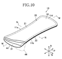
- Fig. 10 is a view similar to Fig. 1 , showing another embodiment of the liner 10 which may be made by the method and the apparatus according to the present invention.
- the first and second compressed lines 21, 22 formed along the side edges 11a, 11b of the liner 10 are connected to each other in the end regions 31, 32 of the liner 10 so as to describe a loop-shaped compressed line 25.
- the second roll 302b constituting the paired compression rolls 302 formed with the anvil-mode first projections 371 and the anvil-mode second projections 372 as exemplarily illustrated by Fig. 5 may be replaced by a second roll 302b formed with a loop-shaped anvil-mode projections corresponding to the compressed loop-shaped line 25 or replaced by the second roll 302b having a smooth peripheral surface.
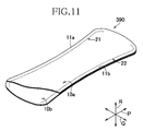
- Fig. 11 also is a view similar to Fig. 1 , showing a still another embodiment of the liner which can be made by the method and the apparatus according to the present invention.
- the liner shown by Fig. 11 is the composite liner 390 comprising an upper liner 10a and a lower liner 10b separably attached together wherein both the upper liner 10a and the lower liner 10b may be same as the liner 10 as shown in Fig. 1 .
- fibrous material (not shown) forming the upper liner 10a is forced into the lower liner 10b along the first compressed line 21 and the second compressed line 22 formed in the upper liner 10a and mechanically entangled with fibrous material (not shown) forming the lower liner 10b.
- Such composite liner 390 may be obtained by, in the process schematically illustrated in Fig. 2 , placing a laminated web 113 indicated by the imaginary lines upon the second laminated web 115 and then feeding these two webs 113, 115 so as to pass through the paired compression rolls 302 in the machine direction MD.
- the laminated web 113 is bodily fluid absorbent web provided on its side facing the second laminated web 115 with a bodily fluid impervious web formed, e.g., by a plastic film.
- the height, pressure and temperature of the projections 351 and the small projections 352 formed on the first roll 302a should be adjusted so that the small compressed spots 20 may extend through the laminated web 113 into the second laminated web 115.
- peel strength of the upper liner 10a along the first and second compressed lines 21, 22 should be substantially of the same degree. Also with respect to a plurality of the composite liners 390 obtained simultaneously in a plurality of rows in the process schematically illustrated in Fig. 2 , the peel strength of the respective composite liners 10a should be substantially of the same degree.
- Such requirements are easily met by using the exemplarily illustrated paired compression rolls 302 according to the present invention since such roll pair facilitates the bodily fluid absorbent web 115 to be evenly compressed over the full width thereof and thereby assures the peel strength of the upper liners 10a of the respective composite liners 390 to be stabilized and to be uniform.
Landscapes
- Health & Medical Sciences (AREA)
- Engineering & Computer Science (AREA)
- Epidemiology (AREA)
- Life Sciences & Earth Sciences (AREA)
- Biomedical Technology (AREA)
- Heart & Thoracic Surgery (AREA)
- Vascular Medicine (AREA)
- Animal Behavior & Ethology (AREA)
- General Health & Medical Sciences (AREA)
- Public Health (AREA)
- Veterinary Medicine (AREA)
- Manufacturing & Machinery (AREA)
- Mechanical Engineering (AREA)
- Fluid Mechanics (AREA)
- Physics & Mathematics (AREA)
- Absorbent Articles And Supports Therefor (AREA)
Abstract
Description
- The present invention relates to methods and apparatuses to make bodily fluid absorbent pads suitable to use in the form of various articles such as panty liners and sanitary napkins.
- Bodily fluid absorbent pad such as panty liners are well known. Such pads shaped to be symmetric with respect to a longitudinal center line as well as a transverse center line are also well known.
- For example, an absorbent article disclosed in
PTL 1 is shaped to be symmetric with respect to a longitudinal center line as well as a transverse center line and comprises a pair of absorbent article components being same in shape as well as in size put flat together in a thickness direction and partially compressed under heating so as to be detachably attached to each other along compressed lines. When the upper absorbent article component has been contacted with a wearer's skin and soiled with bodily fluids, the upper absorbent article component may be peeled off from the lower absorbent article component and in turn, this lower one may be contacted with the wearer's skin. Each of the absorbent articles has a dimension in the transverse direction or the width of the article is larger in end regions opposite in the longitudinal direction than in an intermediate region defined between the end regions. The compressed lines along which the upper and lower absorbent article components are attached together extend in the longitudinal direction along the side edges of the article. -
- PTL 1:
JP 2006-305243 A - In a bodily fluid absorbent web from which the absorbent article components used for the absorbent article disclosed in
PTL 1 are cut out, the individual absorbent article components line up sideways and each pair of the adjacent absorbent article components leaves therebetween a relatively large space since the width of the absorbent article component is larger in the opposite end regions than in the intermediate region. As a consequence, in the step of cutting out the individual absorbent article components inevitably generates scrap in large quantity. Furthermore, when a fibrous web having a thickness in a range of 0.5 to 2 mm is used as the web formed with compressed lines, the depth and the appearance of the compressed lines might become uneven depending on the individual absorbent article components. - The present invention intends to solve such problems occurring in the course of making the bodily fluid absorbent pad.
- The present invention includes a first aspect relating to a method for making a bodily fluid absorbent pad and a second aspect relating to an apparatus for making such bodily fluid absorbent pad.
- According to the present invention on the first aspect, there is provided a method for making a bodily fluid absorbent pad, the pad having a longitudinal direction, a transverse direction and a thickness direction being orthogonal one to another and shaped so as to be relatively long in the longitudinal direction, wherein the pad having a skin-contact surface and a skin-noncontact surface being an opposite surface of the skin-contact surface as viewed in the thickness direction, and a dimension in the transverse direction being larger in first and second end regions opposite to each other in the longitudinal direction than in an intermediate region extending between the first and second end regions, and wherein the pad is formed on the skin-contact surface with compressed lines extending in the longitudinal direction inside respective side edges extending in parallel with each other in the longitudinal direction thereof.
- The present invention on the first aspect thereof includes the steps as follow: feeding a bodily fluid absorbent web in a machine direction through paired compression rolls to partially compress the bodily fluid absorbent web and thereby to form the compressed lines including first and second compressed segments in the first and second end regions, respectively, and third compressed segments extending in the intermediate region, wherein compressing units for forming the compressed lines are provided on and projecting from a peripheral surface of at least one roll constituting the paired compression rolls and the compressing units are adapted to form one row extending in a circumferential direction and also wherein at least one additional row of the compressing units which is adjacent to and in parallel with the one row is provided in an axial direction of the one roll; and wherein there is an offset in the circumferential direction between the compressing units in the one row and the compressing unit in the one additional row so that the first and second compressed segments formed by the compressing units in the one row are lateral to the third compressed segment formed by the compressing unit in the one additional row, respectively; and
making two or more rows of the bodily fluid absorbent pads from the bodily fluid absorbent web. - According to one embodiment of the present invention on the first aspect thereof, the method further includes a step of feeding a bodily fluid absorbent web through paired cutter rolls provided on downstream of the paired compression rolls in the machine direction to cut out the bodily fluid absorbent pads from the bodily fluid absorbent web having passed through the paired compression rolls wherein knife edges are provided on a peripheral surface of one cutter roll constituting the paired cutter rolls and arranged in an arrangement corresponding to an arrangement of the compressing units provided on said one compression roll constituting the paired compression rolls in the circumferential direction as well as in the axial direction.
- According to another embodiment of the present invention on the first aspect thereof, the method further includes, between the step of feeding the bodily fluid absorbent web through the paired compression rolls and the step of feeding the bodily fluid absorbent web through the paired cutter rolls, a step of permanently attaching bodily fluid impervious web defining the skin-noncontact surface in the bodily fluid absorbent pad to the bodily fluid absorbent web.
- According to still another embodiment of the present invention on the first aspect thereof, the method further includes before the step of feeding the bodily fluid absorbent web through the paired compression rolls, a step of placing a second bodily fluid absorbent web upon a skin-contact surface of the bodily fluid absorbent web destined to be the skin-contact surface of the bodily fluid absorbent pad and then separably attaching the bodily fluid absorbent web and the second bodily fluid absorbent web to each other to make bodily fluid absorbent composite pads comprising the bodily fluid absorbent pads.
- According to yet another embodiment of the present invention on the first aspect thereof, the method further characterized in that at least one compression roll constituting the paired compression rolls is formed so as to receive a rod heater inserted thereinto wherein said rod heater is designed so that a watt density is higher at end regions thereof opposite to each other in the axial direction than in an intermediate region thereof extending between the end regions thereof.
- According to the present invention on the second aspect thereof, there is provided an apparatus for implementation of the method for making the bodily fluid absorbent pad.
- The present invention on the second aspect thereof includes in the following features: one compression roll constituting the paired compression rolls adapted to compress the bodily fluid absorbent web has the compressing units projecting from the peripheral surface thereof and arranged in one row extending in a circumferential direction and also arranged in at least one additional row of said compressing units adjacent in an axial direction and extending in parallel with the one row of compressing units and there is an offset in the circumferential direction between the compressing unit in the one row and the compressing unit in the one additional row; and a third region in the one row adapted to form the third compressed segments are lateral to first and second regions in the additional row adapted to form the first and second compressed segments and opposed to each other in the circumferential direction.
- According to one embodiment according to the present invention on the second aspect thereof, paired cutter rolls used to cut out the bodily fluid absorbent pads from the bodily fluid absorbent web is provided on downstream of the paired compression rolls in the machine direction and one cutter roll constituting the paired cutter rolls is provided on a peripheral surface thereof with knife edges in an arrangement corresponding to an arrangement of the compressing units on the one compression roll constituting the paired compression rolls in the circumferential direction as well as in the axial direction wherein the knife edges project from the peripheral surface of the one cutter roll constituting the paired cutter rolls and the other cutter roll of the paired cutter rolls has a smooth peripheral surface.
- According to another embodiment according to the present invention on the second aspect thereof, compressing units are provided on and projected from the peripheral surface of the other one compression roll constituting the paired compression rolls and cooperate with the compressing units on the one compression roll constituting the paired compression rolls to compress the bodily fluid absorbent web.
- According to still another embodiment according to the present invention on the second aspect thereof, the peripheral surface of the one compression roll constituting the paired compression rolls includes regions each surrounded by the third region and the first and second regions opposed to each other in the circumferential direction, and each of these surrounded regions is formed with a small projection adapted to form an additional compressed line appearing in the bodily fluid absorbent web but not in the bodily fluid absorbent pad.
- The method and the apparatus according to the present invention for making the disposable bodily fluid absorbent pad provide advantageous effect as follows: In the process of continuously making the pads, the compressing units formed on the paired compression rolls adapted to act on the web running in the machine direction are set in array so as to form two or more rows in the machine direction and, in each pair of the rows being adjacent in the cross direction, the regions of the compressing units in one row adapted to form in the end regions of the pad with the compressed end segments are lateral to the regions of the compressing units in the adjacent row adapted to form in the intermediate region of the pad with the compressed intermediate segments. The individual pads can be cut out from such web with scrap as reduced as possible. Furthermore, there is no risk that the area over which the paired compression rolls used to form the pads with the compressed lines come in contact with the web might be abruptly changed and thereby might damage the web and/or the paired compression rolls.
-
- {
FIG. 1 }
Fig. 1 is a partially cutaway perspective view of the liner. - {
FIG. 2 }
Fig. 2 is a diagram schematically illustrating a process of making a liner. - {
FIG. 3 }
Fig. 3 illustrates a peripheral surface of the first roll constituting a paired compression rolls as has been flatly developed. - {
FIG. 4 }
Fig. 4 is a sectional view taken along line IV-IV inFig. 3 . - {
FIG. 5 }
Fig. 5 illustrates a peripheral surface of the second roll constituting a paired compression rolls as has been flatly developed. - {
FIG. 6 }
Fig. 6 is a sectional view taken along line VI-VI inFig. 5 . - {
FIG. 7 }
Fig. 7 illustrates a second cutter roll as has been flatly developed. - {
FIG. 8 }
Fig. 8 is a sectional view taken along line VIII-VIII inFig. 7 . - {
FIG. 9 }
Fig. 9 is a side view of a heater. - {
FIG. 10 }
Fig. 10 is a view similar toFig. 1 , showing another embodiment of the liner. - {
FIG. 11 }
Fig. 11 is a view similar toFig. 1 , showing a still another embodiment of the liner. -
- 10
- pad (liner)
- 11
- first pad (upper liner)
- 11a
- side edge
- 11b
- side edge
- 11c
- end edge
- 11d
- end edge
- 20
- small compressed spot(s)
- 21
- compressed line (first compressed line)
- 21c
- first compressed end segment
- 21d
- second compressed end segment
- 21e
- third compressed segment
- 22
- compressed line (second compressed line)
- 22c
- first compressed end segment
- 22d
- second compressed end segment
- 22e
- third compressed segment
- 31
- first end region
- 32
- second end region
- 33
- intermediate region
- 43a
- skin-noncontact surface
- 113
- second bodily fluid absorbent web
- 115
- bodily fluid absorbent web (second laminated web)
- 116
- first composite web
- 117
- second composite web
- 127
- bodily fluid impervious web
- 302
- paired compression rolls
- 302a
- first compression roll
- 302b
- second compression roll
- 330
- cutter roll pair
- 331a
- first cutter roll
- 331b
- second cutter roll
- 341
- third region
- 342
- third region
- 343
- first region
- 344
- second region
- 351
- compressing unit (projection)
- 352
- first projection (small projection)
- 360
- surrounded region
- 361
- second compressing unit (anvil-mode projection)
- 362
- second projection (anvil-mode projection)
- 380
- heater
- 381
- knife edge
- 390
- composite pad
- The present invention will be described in more details in reference to the accompanying drawings on the basis of the panty liner as a typical embodiment of the bodily fluid absorbent pad made by a method and an apparatus according to the present invention.
-
Fig. 1 is a partially cutaway perspective view of apanty liner 10. Apanty liner 10 has a longitudinal direction P, a transverse direction Q and a thickness direction R which are orthogonal one to another, and is symmetrically shaped with respect to the center line M bisecting the dimension thereof in the transverse direction Q as well as the center line N bisecting the dimension thereof in the longitudinal direction P. Theliner 10 is contoured by a pair ofside edges end edges end edges side edges liner 10 is shaped so as to be relatively long in the longitudinal direction P. In the transverse direction Q, theliner 10 is relatively wide inopposite end regions end regions intermediate region 33 extending between theend regions end regions end regions liner 10 and, in theintermediate region 33, theside edges liner 10. - The
liner 10 further includes a top-sheet 40, first and secondintermediate sheets sheet 43 and arelease paper 44 so that a pressure-sensitive adhesive (not shown) coated on the back-sheet 43 can be exposed as therelease paper 44 is peeled off from the back-sheet 43. Theliner 10 is formed along theside edge 11a thereof with a firstcompressed line 21 and along theside edge 11b thereof with a secondcompressed line 22 which is symmetric with the firstcompressed line 21 in the transverse direction Q. Both the firstcompressed line 21 and the secondcompressed line 22 are assemblies comprising a plurality of smallcompressed spots 20 arranged in the longitudinal direction P so as to be spaced apart one from another and to define respective queues extending into theopposite end regions liner 10. In theend regions compressed line 21 and the secondcompressed line 22 are spaced from each other by a dimension W as measured in the transverse direction Q. The firstcompressed line 21 includescompressed end segments respective end regions intermediate segment 21e in theintermediate region 33 between thecompressed end segments compressed line 22 includescompressed end segments intermediate segment 22e. As will be described later more in detail, the top-sheet 40 and the first and secondintermediate sheets liner 10 are locally compressed by the paired compression rolls with or without heating to obtain the smallcompressed spots 20. In each of these smallcompressed spots 20, materials respectively forming thesesheets sheets side edges liner 10 with a decorative effect. -
Such liner 10 has basically a laminated structure comprising the bodily fluid pervious top-sheet 40 made of a non-woven fabric containing thermoplastic synthetic fibers or a perforated plastic film, the first and secondintermediate sheets sheet 43 made of a plastic film or a non-woven fabric containing thermoplastic synthetic fibers. These sheets placed one upon another are permanently attached together by hot melt adhesive (not shown) so that the top-sheet 40 cooperates with the first and secondintermediate sheets sheet 43 forms a bodily fluid impervious layer adapted to prevent bodily fluids from transferring to the wearer's garment. The thermoplastic synthetic fibers contained in the bodily fluid absorbing/containing layer are preferably modified to become hydrophilic. This layer may contain liquid-absorbent fibers such as pulp fibers. The top-sheet 40 defines the skin-contact surface of theliner 10 and the back-sheet 43 defines the skin-noncontact surface of theliner 10 opposed to the skin-contact surface, i.e., the garment-contact surface 43a adapted to be put in contact with the wearer's garment (not shown). This garment-contact surface 43a is coated with pressure-sensitive adhesive (not shown) which is, in turn, protectively covered with aseparator 44. - The exemplarily illustrated
liner 10 is shaped to be symmetric with respect to the center line M as well as the center line N so that theliner 10 can be properly put on the wearer's body whether theend 11c is in front or theend 11d is in front. However, it is not essential for theliner 10 to be symmetric with respect to the center line N and it is possible to shape theliner 10 asymmetrically with respect to the center line N depending on the intended purpose. -
Fig. 2 exemplarily and schematically illustrates a process of making theliner 10. The process includes a first section A to obtain the bodily fluid absorbent layer of theliner 10, a second section B to obtain the bodily fluid impervious layer after the bodily fluid absorbent layer has been formed with the first and secondcompressed lines - The first section A includes a
first step 105 through athird step 107. Specifically, in thefirst step 105, afirst web 124 from which the top-sheet 40 will be obtained and asecond web 125 from which the firstintermediate sheet 41 will be obtained are fed from the right hand as viewed inFig. 2 in a machine direction MD. Also in thefirst step 105, acoater 204 is used to coat one surface of thesecond web 125 with hot melt adhesive (not shown). - In the
second step 106, the first andsecond webs rolls 209 and attached to each other by hot melt adhesive coated on thesecond web 125 to obtain a firstlaminated web 114. - In the
third step 107, athird web 126 from which the secondintermediate sheet 42 will be obtained is fed in the machine direction MD and, in the course of feeding thisthird web 126, a coater 212 is used to coat one surface of thethird web 126 with hot melt adhesive (not shown). Also in thethird step 107, paired rolls 213 rotating in the machine direction MD is used to attach the firstlaminated web 114 to thethird web 126 having been coated with hot melt adhesive and thereby to obtain a secondlaminated web 115. - The second section B includes a
fourth step 108 and afifth step 110. Specifically, in thefourth step 108, the secondlaminated web 115 being kept by atension controller 301 under a predetermined tension in the machine direction MD is fed to paired compression rolls 302 consisting of afirst roll 302a and asecond roll 302b. Thefirst roll 302a is formed on its peripheral surface with projections 351 (SeeFigs. 3 and4 ) corresponding to the respective small compressed spots 20 (SeeFig. 1 ) while thesecond roll 302b is formed on its peripheral surface with anvil-mode projections 361 (SeeFigs. 5 and6 ) opposed to the associatedprojections 351. Passing through the paired compression rolls 302, regions of the secondlaminated web 115 in which the firstcompressed line 21 and the secondcompressed line 22 will be formed are compressed so that at least the first, second andthird webs laminated web 115 may be mechanically entangled together. In this way, a firstcomposite web 116 is obtained. To enhance a compressing effect, it is also possible to use the first and second compression rolls 302a, 302b under heating. Also in thefourth step 108, acoater 303 is used to coat thethird web 126 constituting the firstcomposite web 116 with hot melt adhesive (not shown). - In the
fifth step 109, afourth web 127, a bodily fluid impervious web from which the back-sheet 43 of theliner 10 will be obtained and afifth web 128 from which the separator 47 of theliner 10 will be obtained are fed in the machine direction MD. Acoater 306 is used to coat one surface of thefifth web 128 with hot melt adhesive (not shown). Thefourth web 127 and thefifth web 128 are fed to pairedrolls 318 to attach these fourth andfifth webs fifth web 128. Then thefourth web 127 is put flat upon thethird web 126 of the firstcomposite web 116 previously coated with adhesive by thecoater 303. Thefourth web 127, thefifth web 128 and the firstcomposite web 116 are fed so as to pass through pairedrolls 319 and to be attached together. In this way, a secondcomposite web 117 is obtained. - In the
sixth step 110 of the third section C, the secondcomposite web 117 is continuously fed to paired cutter rolls 330 consisting of tworolls individual composites 350, i.e., theindividual liners 10 as shown inFig. 1 are successively cut out from theweb 117. - In downstream steps subsequent to the
sixth step 110, appropriate means such as paired conveyer rolls 321 or anendless belt 322 is used to convey theindividual composites 350 in the machine direction MD and, in the course of conveying, thesecomposites 350 are successively wrapped, for example, by the plastic film to obtain envelopes each containing therein theliner 10. - Referring to
Figs. 3 and4 ,Fig. 3 illustrates the peripheral surface of thefirst roll 302a constituting the paired compression rolls 302 used in the process illustrated inFig. 2 as has been flatly developed andFig. 4 is a sectional view taken along line IV-IV inFig. 3 . Thefirst roll 302a depicted inFig. 3 is formed on the peripheral surface thereof with, in addition to a plurality of loop-shapedprojections 351 adapted to form the firstcompressed line 21 and the secondcompressed line 22, a plurality ofsmall projections 352 extending in the machine direction MD. Theseprojections 351 and thesmall projections 352 have profiles as illustrated byFig. 4 . Theprojections 351 and thesmall projections 352 shaded inFig. 3 for convenience of illustration respectively havetop surfaces top surfaces 353 are formed with a plurality of small projections shaped so as to correspond to the smallcompressed spots 20 as shown byFig. 1 . Each of theprojections 351 is necessary and sufficient to form all compressed lines included in theindividual liner 10 and, from the viewpoint of this, each of theprojections 351 can be referred to as "compressing unit". Theseprojections 351 formed on the peripheral surface of thefirst roll 302a are arranged in five rows each extending to the machine direction MD wherein the first row includes theprojections projections projections projections projections projections 351a through 351o referred to herein generically as theprojection 351 are the same in shape as well as in size and respectively include in addition tolateral projection segments intermediate segments compressed lines region projection segments lateral projection segments compressed end segments respective end regions projections 351 being adjacent in the machine direction MD may be spaced from each other by a dimension X. In each pair of the rows being adjacent in the cross direction CD, for example, in the first and second rows, the endregion projection segment 343 of theprojection 351d and the endregion projection segment 344 of theprojection 351e in the second row are positioned adjacent thelateral projection segment 342 of theprojection 351a in the first row as viewed in the cross direction CD. In this manner, there is an offset between theprojection 351 of the first row and theprojection 351 of the second row and the offset is in the length of approximately by a half of the length of theprojection 351. As explained, the first row includes theprojections 351a - 351c as theprojection 351 and the second row includes theprojection 351d - 351f as theprojection 351. The endregion projection segment 343 of theprojection 351d is opposed to the endregion projection segment 344 of theprojection 351e in the machine direction MD. On suchfirst roll 302a, thelateral projection segment 342 of theprojection 351a in the first row, the endregion projection segment 343 of theprojection 351d and the endregion projection segment 344 of theprojection 351e surround aregion 360 in which thesmall projection 352 is formed. Suchsmall projection 352 has the same height as that of theprojection 351. Referring toFig. 3 , the secondlaminated web 115 fed to the paired compression rolls 302 is indicated by imaginary lines. -
Fig. 5 illustrates the peripheral surface of thesecond roll 302b constituting the paired compression rolls 302 as has been flatly developed andFig. 6 is a sectional view taken along line VI-VI inFig. 5 . Referring toFig. 5 , the secondlaminated web 115 is indicated by imaginary lines. Thesecond roll 302b provides anvils adapted to cooperate with the associatedprojections 351 on thefirst roll 302a and, more specifically, thesecond roll 302b is formed on its peripheral surface with anvil-mode projections 361 opposed to the associatedprojections 351 by the intermediary with the secondlaminated web 115 and anvil-modesmall projections 362 opposed to the associatedsmall projections 352. It should be appreciated that each of the anvil-mode projections 361 comprises an anvil-modefirst projection 371 and an anvil-modesecond projection 372 spaced from and opposite to each other in the cross direction CD. The anvil-modefirst projection 371 cooperates with the associatedprojection 351 to form the firstcompressed line 21 in theliner 10 and has the same planar shape as the firstcompressed line 21. The anvil-modesecond projection 372 cooperates with the associatedprojection 351 to form the secondcompressed line 22 in theliner 10 and has a same planar shape as the secondcompressed line 22. Thesecond roll 302b is provided with aregion 370 between respective ends of these anvil-mode first and second projections spaced from each other in the cross direction CD by a dimension W and thisregion 370 leaves a non-compressed region in the secondlaminated web 115. These anvil-mode projections 361 are compressing units adapted to complement the associatedprojections 351. These anvil-mode projections 361 are arranged in the machine direction MD to form rows wherein a first row includes the anvil-mode projections mode projections mode projections mode projections mode projections mode projections 361 in these five rows cooperate with the associatedprojections 351 in the five rows to form the secondlaminated web 115 with the first and secondcompressed lines small projections 362 cooperate with the associatedsmall projections 352 to compress the secondlaminated web 115. - With the paired compression rolls 302 designed as has been described above, the
liners 10 can be obtained in a plurality of rows at once and, in the respective rows, theliners 10 can be obtained intermittently in the machine direction MD. On thefirst roll 302a, the endregion projection segment 343 of theprojection 351d and the endregion projection segment 344 of theprojection 351e both describing convexly curved lines in the second row are positioned closely to, as viewed in the cross direction CD, the concavely curved line describinglateral projection segment 342 of theprojection 351a in the first row. Such arrangement allows a given area of the secondlaminated web 115 to be used to make theliners 10 as efficiently as possible and thereby allows scrap inevitably generated when theliners 10 are cut out from the secondlaminated web 115 to be reduced. In contrast with the arrangement of theprojections 351 and the anvil-mode projections 361 as illustrated byFigs. 3 and5 , it is assumed that theseprojections 351 and anvil-mode projections 361 of the respective rows are aligned in the cross direction CD. In this case, between each pair of the concavely curved line describinglateral compression segments liners 10 have been cut out from the secondlaminated web 115. - In the paired compression rolls 302, the regions used to compress the bodily fluid
absorbent web 115 includes theprojections 351 formed on the peripheral surface of thefirst roll 302a and the anvil-mode projections 361 formed on the peripheral surface of thesecond roll 302b. Consequentially, the first andsecond rolls projections respective projections compressed line 21 and the secondcompressed line 22 can be neatly formed. - With the paired compression rolls 302 as illustrated in
Figs. 3 through 6 , the presence of thesmall projections 352 and the anvil-modesmall projections 362 provide another advantageous effect. More specifically, thesesmall projections 352 and anvil-modesmall projections 362 also anticipate to compress the secondlaminated web 115 and, in consequence, an area over which thefirst roll 302a and thesecond roll 302b come in contact with the secondlaminated web 115 is not be abruptly changed. In this way, the possibility that the secondlaminated web 115 and the first andsecond rolls small projections 352 nor the anvil-modesmall projections 362. Furthermore, thefirst roll 302a is formed with thesmall projections 352 not only at opposite ends in the axial direction but also between each pair of the adjacent rows of theprojections 351. In a similar way, thesecond roll 302b is formed with the anvil-modesmall projections 362 not only at opposite ends in the axial direction but also between each pair of the adjacent rows of the anvil-mode projections 361. With this unique arrangement, the bodily fluidabsorbent web 115 can be evenly compressed not only at the transversely opposite side regions thereof but also at the intermediate region thereof in the step of compressing theweb 115 and thereby it is possible to restrict the bodily fluid absorbent web over its full width from undesirable displacement in the machine direction MD as well as in the cross direction CD. It is thus easy for the first andsecond rolls web 115 from being biased in the cross direction CD. -
Fig. 7 illustrates thefirst cutter roll 331a constituting the paired cutter rolls 330 illustrated inFig. 2 as has been flatly developed andFig. 8 is a sectional view taken along line VIII-VIII inFig. 7 . Referring toFig. 7 , thefirst cutter roll 331a is formed on its peripheral surface with a plurality of oval knife edges 381 each having a shape conforming to the contour shape of theliner 10 shown inFig. 1 . The knife edges 381 are arranged in the machine direction MD at the same pitch as the pitch at which theprojections 351 are arranged in the machine direction MD on thefirst compression roll 302a so that a plurality of rows of the knife edges 381 may be formed. In each pair of the rows being adjacent in the cross direction CD, there is an offset between the one row having the knife edges 381 arranged in the machine direction MD and the other row having the knife edges 381 arranged in the machine direction MD and the offset is in the length of approximately by a half of the inner diameter of the individual knife edge 281 as measured in the machine direction MD. Thesecond cutter roll 331b cooperating with suchfirst cutter roll 331a has a smooth peripheral surface. -
Fig. 9 is a side view of arod heater 380 adapted to be inserted into shaft (s) of thefirst roll 302a and/or thesecond roll 302b of the paired compression rolls 302 and thereby to control a surface temperature of theprojections 351 and/or the anvil-mode projections 361 at a desired temperature level. Therod heater 380 is used to maintain the peripheral surface of the roll incorporated with therod heater 380 at an even temperature in the axial direction and thereby to assure two ormore liners 10 arranged in the cross direction CD to have the first and second lateralcompressed segments rod heater 380 is designed to have a watt density higher at longitudinally opposite end regions than in a longitudinally intermediate region. Specifically, taking account of a fact that thefirst roll 302a and/or thesecond roll 302b may typically have heat loss higher in the axially opposite end region than in the axially intermediate region, the watt density distribution of therod heater 380 in the longitudinal direction thereof is previously adjusted in order to compensate the heat loss. When the first and secondcompressed lines Fig. 11 ), use of therod heater 380 as illustrated inFig. 9 will be essential since it is important to assure that the first and secondcompressed lines liners 10 are properly formed. -
Fig. 10 is a view similar toFig. 1 , showing another embodiment of theliner 10 which may be made by the method and the apparatus according to the present invention. In theliner 10 shown inFig. 10 , the first and secondcompressed lines side edges liner 10 are connected to each other in theend regions liner 10 so as to describe a loop-shapedcompressed line 25. To obtain such loop-shapedcompressed line 25, thesecond roll 302b constituting the paired compression rolls 302 formed with the anvil-modefirst projections 371 and the anvil-modesecond projections 372 as exemplarily illustrated byFig. 5 may be replaced by asecond roll 302b formed with a loop-shaped anvil-mode projections corresponding to the compressed loop-shapedline 25 or replaced by thesecond roll 302b having a smooth peripheral surface. -
Fig. 11 also is a view similar toFig. 1 , showing a still another embodiment of the liner which can be made by the method and the apparatus according to the present invention. The liner shown byFig. 11 is thecomposite liner 390 comprising anupper liner 10a and alower liner 10b separably attached together wherein both theupper liner 10a and thelower liner 10b may be same as theliner 10 as shown inFig. 1 . However, it should be appreciated that fibrous material (not shown) forming theupper liner 10a is forced into thelower liner 10b along the firstcompressed line 21 and the secondcompressed line 22 formed in theupper liner 10a and mechanically entangled with fibrous material (not shown) forming thelower liner 10b. Suchcomposite liner 390 may be obtained by, in the process schematically illustrated inFig. 2 , placing alaminated web 113 indicated by the imaginary lines upon the secondlaminated web 115 and then feeding these twowebs laminated web 113 is bodily fluid absorbent web provided on its side facing the secondlaminated web 115 with a bodily fluid impervious web formed, e.g., by a plastic film. In the paired compression rolls 302 used for this embodiment, height, pressure and temperature of theprojections 351 and thesmall projections 352 formed on thefirst roll 302a should be adjusted so that the smallcompressed spots 20 may extend through thelaminated web 113 into the secondlaminated web 115. In the individualcomposite liner 390, peel strength of theupper liner 10a along the first and secondcompressed lines composite liners 390 obtained simultaneously in a plurality of rows in the process schematically illustrated inFig. 2 , the peel strength of the respectivecomposite liners 10a should be substantially of the same degree. Such requirements are easily met by using the exemplarily illustrated paired compression rolls 302 according to the present invention since such roll pair facilitates the bodily fluidabsorbent web 115 to be evenly compressed over the full width thereof and thereby assures the peel strength of theupper liners 10a of the respectivecomposite liners 390 to be stabilized and to be uniform.
Claims (9)
- A method for making a bodily fluid absorbent pad, the pad having a longitudinal direction, a transverse direction and a thickness direction being orthogonal one to another and shaped so as to be relatively long in the longitudinal direction, wherein the pad has a skin-contact surface and a skin-noncontact surface being an opposite surface to the skin-contact surface as viewed in the thickness direction, and a dimension in the transverse direction being larger in first and second end regions opposite to each other in the longitudinal direction than in an intermediate region extending between the first and second end regions, and wherein the pad is formed on the skin-contact surface with compressed lines extending in the longitudinal direction inside respective side edges extending in parallel with each other in the longitudinal direction thereof, the method comprising the steps of:feeding a bodily fluid absorbent web in a machine direction through paired compression rolls to partially compress the bodily fluid absorbent web and thereby to form the compressed lines comprising first and second compressed segments in the first and second end regions, respectively, and third compressed segments extending in the intermediate region, wherein compressing units for forming the compressed lines are provided on and projecting from a peripheral surface of at least one roll constituting the paired compression rolls and the compressing units are adapted to form one row extending in a circumferential direction of the one roll, and also wherein at least one additional row of the compressing units is provided which is parallel with the one row and adjacent in an axial direction of the one roll; and wherein there is an offset in the circumferential direction between the compressing unit in the one row and the compressing unit in the one additional row so that the first and second compressed segments formed by the compressing units in the one row are lateral to the third compressed segment formed by the compressing unit in the one additional row, respectively; andmaking two or more rows of the bodily fluid absorbent pads from the bodily fluid absorbent web.
- The method according to Claim 1, further including a step of:feeding a bodily fluid absorbent web through paired cutter rolls provided downstream of the paired compression rolls in the machine direction to cut out the bodily fluid absorbent pads from the bodily fluid absorbent web having passed through the paired compression rolls wherein knife edges are provided on a peripheral surface of one cutter roll constituting the paired cutter rolls and arranged in an arrangement corresponding to an arrangement of the compressing units provided on the one compression roll constituting the paired compression rolls in the circumferential direction as well as in the axial direction.
- The method according to Claim 1 or 2, further including, between the step of feeding the bodily fluid absorbent web through the paired compression rolls and the step of feeding the bodily fluid absorbent web through the paired cutter rolls, a step of permanently attaching a bodily fluid impervious web defining the skin-noncontact surface of the bodily fluid absorbent pad to the bodily fluid absorbent web.
- The method according to any one of Claims 1 through 3, including, before the step of feeding the bodily fluid absorbent web through the paired compression rolls, a step of placing a second bodily fluid absorbent web upon a skin-contact surface of the bodily fluid absorbent web destined to be the skin-contact surface of the bodily fluid absorbent pad and then separably attaching the bodily fluid absorbent web and the second bodily fluid absorbent web to each other to make bodily fluid absorbent composite pads comprising the bodily fluid absorbent pads.
- The method according to any one of Claims 1 through 4, further includes at least one compression roll constituting the paired compression rolls being formed so as to receive a rod heater inserted thereinto wherein the rod heater is designed so that a watt density is higher at end regions thereof opposite to each other in the axial direction than in an intermediate region thereof extending between the end regions.
- An apparatus for implementation of the method according to Claim 1, the apparatus includes:one compression roll constituting the paired compression rolls adapted to compress the bodily fluid absorbent web having the compressing units projecting from the peripheral surface thereof and arranged in one row extending in a circumferential direction and also arranged in at least one additional row of the compressing units adjacent in an axial direction and extending in parallel with the one row of compressing units and there being an offset in the circumferential direction between the compressing unit in the one row and the compressing unit in the one additional row; anda third region in the one row adapted to form the third compressed segments being lateral to first and second regions in the additional row adapted to form the first and second compressed segments and opposed to each other in the circumferential direction.
- The apparatus according to Claim 6, wherein paired cutter rolls used to cut out the bodily fluid absorbent pads from the bodily fluid absorbent web are provided downstream of the paired compression rolls in the machine direction and one cutter roll constituting the paired cutter pair is provided on a peripheral surface thereof with knife edges in an arrangement corresponding to an arrangement of the compressing units on the one compression roll constituting the paired compression rolls in the circumferential direction as well as in the axial direction wherein the knife edges project from the peripheral surface of the one cutter roll constituting the paired cutter rolls and the other cutter roll of the paired cutter rolls has a smooth peripheral surface.
- The apparatus according to Claim 6 or 7, wherein compressing units are provided on and projected from the peripheral surface of the other one compression roll constituting the paired compression rolls and cooperate with the compressing units on the one compression roll constituting the paired compression rolls to compress the bodily fluid absorbent web.
- The apparatus according to any one of Claims 6 through 8, wherein the peripheral surface of the one compression roll constituting the paired compression rolls includes regions each surrounded by the third region and the first and second regions opposed to each other in the circumferential direction, and each of these surrounded regions is formed with a small projection adapted to form an additional compressed line appearing in the bodily fluid absorbent web but not in the bodily fluid absorbent pad.
Applications Claiming Priority (2)
| Application Number | Priority Date | Filing Date | Title |
|---|---|---|---|
| JP2009156295A JP5414106B2 (en) | 2009-06-30 | 2009-06-30 | Method and apparatus for manufacturing body fluid absorbent pad |
| PCT/JP2009/063021 WO2011001543A1 (en) | 2009-06-30 | 2009-07-21 | Method for producing bodily fluid-absorbing pad and production device therefor |
Publications (2)
| Publication Number | Publication Date |
|---|---|
| EP2450011A1 true EP2450011A1 (en) | 2012-05-09 |
| EP2450011A4 EP2450011A4 (en) | 2014-03-05 |
Family
ID=42629412
Family Applications (1)
| Application Number | Title | Priority Date | Filing Date |
|---|---|---|---|
| EP09846835.8A Withdrawn EP2450011A4 (en) | 2009-06-30 | 2009-07-21 | Method for producing bodily fluid-absorbing pad and production device therefor |
Country Status (11)
| Country | Link |
|---|---|
| US (2) | US8268211B2 (en) |
| EP (1) | EP2450011A4 (en) |
| JP (1) | JP5414106B2 (en) |
| CN (1) | CN102458328A (en) |
| AR (1) | AR077299A1 (en) |
| AU (1) | AU2009324277A1 (en) |
| BR (1) | BRPI0924470A2 (en) |
| CO (1) | CO6361879A2 (en) |
| SG (1) | SG176690A1 (en) |
| TW (1) | TW201116262A (en) |
| WO (1) | WO2011001543A1 (en) |
Families Citing this family (2)
| Publication number | Priority date | Publication date | Assignee | Title |
|---|---|---|---|---|
| JP5604231B2 (en) | 2010-08-31 | 2014-10-08 | ユニ・チャーム株式会社 | Press device and press method for absorbent article |
| CN103517693B (en) * | 2011-03-15 | 2015-11-25 | Sca卫生用品公司 | For pruning the method and apparatus of material from web |
Family Cites Families (7)
| Publication number | Priority date | Publication date | Assignee | Title |
|---|---|---|---|---|
| US4862574A (en) * | 1987-02-24 | 1989-09-05 | Personal Products Company | Panty protector |
| AU1688397A (en) * | 1996-01-26 | 1997-08-20 | Kimberly-Clark Worldwide, Inc. | A knife shaft assembly |
| US6913718B2 (en) * | 2001-11-05 | 2005-07-05 | Rayonier Products & Financial Services Company | Method of making shaped components for disposable absorbent articles |
| JP4162609B2 (en) * | 2004-02-05 | 2008-10-08 | 花王株式会社 | Method for manufacturing absorbent article |
| JP4017616B2 (en) * | 2004-07-09 | 2007-12-05 | 花王株式会社 | Embossed groove formability evaluation method |
| JP2006158538A (en) * | 2004-12-03 | 2006-06-22 | Kao Corp | Method for manufacturing absorbent article |
| JP4738049B2 (en) * | 2005-05-02 | 2011-08-03 | ユニ・チャーム株式会社 | Absorbent articles |
-
2009
- 2009-06-30 JP JP2009156295A patent/JP5414106B2/en not_active Expired - Fee Related
- 2009-07-21 US US12/524,085 patent/US8268211B2/en not_active Expired - Fee Related
- 2009-07-21 AU AU2009324277A patent/AU2009324277A1/en not_active Abandoned
- 2009-07-21 SG SG2011090073A patent/SG176690A1/en unknown
- 2009-07-21 EP EP09846835.8A patent/EP2450011A4/en not_active Withdrawn
- 2009-07-21 CN CN2009801601737A patent/CN102458328A/en active Pending
- 2009-07-21 BR BRPI0924470A patent/BRPI0924470A2/en not_active IP Right Cessation
- 2009-07-21 WO PCT/JP2009/063021 patent/WO2011001543A1/en not_active Ceased
-
2010
- 2010-06-29 TW TW99121236A patent/TW201116262A/en unknown
- 2010-06-30 AR ARP100102336 patent/AR077299A1/en unknown
- 2010-08-06 CO CO10096560A patent/CO6361879A2/en active IP Right Grant
-
2012
- 2012-08-15 US US13/586,313 patent/US9314379B2/en not_active Expired - Fee Related
Also Published As
| Publication number | Publication date |
|---|---|
| CN102458328A (en) | 2012-05-16 |
| TW201116262A (en) | 2011-05-16 |
| US20110154964A1 (en) | 2011-06-30 |
| WO2011001543A1 (en) | 2011-01-06 |
| BRPI0924470A2 (en) | 2016-02-16 |
| US9314379B2 (en) | 2016-04-19 |
| CO6361879A2 (en) | 2012-01-20 |
| US8268211B2 (en) | 2012-09-18 |
| AU2009324277A1 (en) | 2010-08-05 |
| SG176690A1 (en) | 2012-01-30 |
| JP2011010772A (en) | 2011-01-20 |
| EP2450011A4 (en) | 2014-03-05 |
| US20130037218A1 (en) | 2013-02-14 |
| JP5414106B2 (en) | 2014-02-12 |
| AR077299A1 (en) | 2011-08-17 |
Similar Documents
| Publication | Publication Date | Title |
|---|---|---|
| FI97523C (en) | Absorbent body | |
| CA2790385C (en) | Apparatus and method for forming absorbent cores | |
| CA2719438C (en) | Method and apparatus for stretching segmented stretchable film and application of the segmented film to a moving web | |
| CZ384596A3 (en) | Absorption article, process of its production and apparatus for making the same | |
| CN106535844B (en) | Method for manufacturing absorbent for absorbent article | |
| EP2223670A1 (en) | Absorbent article and method of producing the same | |
| EP3298997B1 (en) | Absorbent article | |
| RU2665904C1 (en) | Cellulose-free absorbent core and a core forming method | |
| JP3719975B2 (en) | Absorber manufacturing method | |
| US20160137450A1 (en) | Adhesive contamination resistant web processing unit | |
| US9314379B2 (en) | Apparatus for making bodily fluid absorbent pad | |
| EP4112026B1 (en) | Composite web | |
| WO2016002290A1 (en) | Absorbent article | |
| CN105792784A (en) | Absorbent body fabrication method | |
| US12589036B2 (en) | Composite web | |
| US8535468B2 (en) | Method for making disposable bodily fluid handling composite pad | |
| JPH10337304A (en) | Absorbent for absorbent article and method for producing the same | |
| US6656311B2 (en) | Apparatus and process for converting asymmetrically nested absorbent webs |
Legal Events
| Date | Code | Title | Description |
|---|---|---|---|
| PUAI | Public reference made under article 153(3) epc to a published international application that has entered the european phase |
Free format text: ORIGINAL CODE: 0009012 |
|
| 17P | Request for examination filed |
Effective date: 20120106 |
|
| AK | Designated contracting states |
Kind code of ref document: A1 Designated state(s): AT BE BG CH CY CZ DE DK EE ES FI FR GB GR HR HU IE IS IT LI LT LU LV MC MK MT NL NO PL PT RO SE SI SK SM TR |
|
| DAX | Request for extension of the european patent (deleted) | ||
| A4 | Supplementary search report drawn up and despatched |
Effective date: 20140203 |
|
| RIC1 | Information provided on ipc code assigned before grant |
Ipc: A61F 13/15 20060101AFI20140128BHEP Ipc: A61F 13/472 20060101ALI20140128BHEP Ipc: A61F 13/475 20060101ALI20140128BHEP |
|
| STAA | Information on the status of an ep patent application or granted ep patent |
Free format text: STATUS: THE APPLICATION HAS BEEN WITHDRAWN |
|
| 18W | Application withdrawn |
Effective date: 20140402 |