EP2449962B1 - Visualization of catheter-tissue contact by map distortion - Google Patents
Visualization of catheter-tissue contact by map distortion Download PDFInfo
- Publication number
- EP2449962B1 EP2449962B1 EP11187708.0A EP11187708A EP2449962B1 EP 2449962 B1 EP2449962 B1 EP 2449962B1 EP 11187708 A EP11187708 A EP 11187708A EP 2449962 B1 EP2449962 B1 EP 2449962B1
- Authority
- EP
- European Patent Office
- Prior art keywords
- force
- probe
- distal end
- body cavity
- simulated surface
- Prior art date
- Legal status (The legal status is an assumption and is not a legal conclusion. Google has not performed a legal analysis and makes no representation as to the accuracy of the status listed.)
- Active
Links
- 238000012800 visualization Methods 0.000 title description 9
- 239000000523 sample Substances 0.000 claims description 52
- 238000005259 measurement Methods 0.000 claims description 34
- 238000000034 method Methods 0.000 claims description 22
- 238000013507 mapping Methods 0.000 claims description 13
- 230000000694 effects Effects 0.000 claims description 7
- 238000003825 pressing Methods 0.000 claims description 7
- 238000002059 diagnostic imaging Methods 0.000 claims description 6
- 238000002591 computed tomography Methods 0.000 claims description 4
- 238000003780 insertion Methods 0.000 claims description 4
- 230000037431 insertion Effects 0.000 claims description 4
- 238000002595 magnetic resonance imaging Methods 0.000 claims description 4
- 210000000056 organ Anatomy 0.000 description 9
- 210000005242 cardiac chamber Anatomy 0.000 description 5
- 238000004040 coloring Methods 0.000 description 4
- 238000010586 diagram Methods 0.000 description 4
- 230000001225 therapeutic effect Effects 0.000 description 4
- 210000002837 heart atrium Anatomy 0.000 description 3
- 230000001766 physiological effect Effects 0.000 description 3
- 238000002405 diagnostic procedure Methods 0.000 description 2
- 230000006870 function Effects 0.000 description 2
- BASFCYQUMIYNBI-UHFFFAOYSA-N platinum Chemical compound [Pt] BASFCYQUMIYNBI-UHFFFAOYSA-N 0.000 description 2
- 229910000575 Ir alloy Inorganic materials 0.000 description 1
- 229910001260 Pt alloy Inorganic materials 0.000 description 1
- 230000001746 atrial effect Effects 0.000 description 1
- 239000003086 colorant Substances 0.000 description 1
- 238000013170 computed tomography imaging Methods 0.000 description 1
- 238000010276 construction Methods 0.000 description 1
- 229910003460 diamond Inorganic materials 0.000 description 1
- 239000010432 diamond Substances 0.000 description 1
- 238000011156 evaluation Methods 0.000 description 1
- 239000004744 fabric Substances 0.000 description 1
- 230000004927 fusion Effects 0.000 description 1
- 239000000463 material Substances 0.000 description 1
- 239000007769 metal material Substances 0.000 description 1
- 230000003287 optical effect Effects 0.000 description 1
- 230000004044 response Effects 0.000 description 1
- 238000002560 therapeutic procedure Methods 0.000 description 1
- 230000002792 vascular Effects 0.000 description 1
- 230000000007 visual effect Effects 0.000 description 1
Images


Classifications
-
- A—HUMAN NECESSITIES
- A61—MEDICAL OR VETERINARY SCIENCE; HYGIENE
- A61B—DIAGNOSIS; SURGERY; IDENTIFICATION
- A61B5/00—Measuring for diagnostic purposes; Identification of persons
- A61B5/68—Arrangements of detecting, measuring or recording means, e.g. sensors, in relation to patient
- A61B5/6846—Arrangements of detecting, measuring or recording means, e.g. sensors, in relation to patient specially adapted to be brought in contact with an internal body part, i.e. invasive
- A61B5/6847—Arrangements of detecting, measuring or recording means, e.g. sensors, in relation to patient specially adapted to be brought in contact with an internal body part, i.e. invasive mounted on an invasive device
- A61B5/6852—Catheters
-
- A—HUMAN NECESSITIES
- A61—MEDICAL OR VETERINARY SCIENCE; HYGIENE
- A61B—DIAGNOSIS; SURGERY; IDENTIFICATION
- A61B5/00—Measuring for diagnostic purposes; Identification of persons
- A61B5/68—Arrangements of detecting, measuring or recording means, e.g. sensors, in relation to patient
- A61B5/6846—Arrangements of detecting, measuring or recording means, e.g. sensors, in relation to patient specially adapted to be brought in contact with an internal body part, i.e. invasive
- A61B5/6885—Monitoring or controlling sensor contact pressure
-
- A—HUMAN NECESSITIES
- A61—MEDICAL OR VETERINARY SCIENCE; HYGIENE
- A61B—DIAGNOSIS; SURGERY; IDENTIFICATION
- A61B5/00—Measuring for diagnostic purposes; Identification of persons
- A61B5/74—Details of notification to user or communication with user or patient ; user input means
- A61B5/742—Details of notification to user or communication with user or patient ; user input means using visual displays
-
- A—HUMAN NECESSITIES
- A61—MEDICAL OR VETERINARY SCIENCE; HYGIENE
- A61B—DIAGNOSIS; SURGERY; IDENTIFICATION
- A61B18/00—Surgical instruments, devices or methods for transferring non-mechanical forms of energy to or from the body
- A61B2018/00636—Sensing and controlling the application of energy
- A61B2018/00773—Sensed parameters
- A61B2018/00839—Bioelectrical parameters, e.g. ECG, EEG
-
- A—HUMAN NECESSITIES
- A61—MEDICAL OR VETERINARY SCIENCE; HYGIENE
- A61B—DIAGNOSIS; SURGERY; IDENTIFICATION
- A61B34/00—Computer-aided surgery; Manipulators or robots specially adapted for use in surgery
- A61B34/20—Surgical navigation systems; Devices for tracking or guiding surgical instruments, e.g. for frameless stereotaxis
- A61B2034/2046—Tracking techniques
- A61B2034/2051—Electromagnetic tracking systems
-
- A—HUMAN NECESSITIES
- A61—MEDICAL OR VETERINARY SCIENCE; HYGIENE
- A61B—DIAGNOSIS; SURGERY; IDENTIFICATION
- A61B90/00—Instruments, implements or accessories specially adapted for surgery or diagnosis and not covered by any of the groups A61B1/00 - A61B50/00, e.g. for luxation treatment or for protecting wound edges
- A61B90/06—Measuring instruments not otherwise provided for
- A61B2090/064—Measuring instruments not otherwise provided for for measuring force, pressure or mechanical tension
- A61B2090/065—Measuring instruments not otherwise provided for for measuring force, pressure or mechanical tension for measuring contact or contact pressure
-
- A—HUMAN NECESSITIES
- A61—MEDICAL OR VETERINARY SCIENCE; HYGIENE
- A61B—DIAGNOSIS; SURGERY; IDENTIFICATION
- A61B34/00—Computer-aided surgery; Manipulators or robots specially adapted for use in surgery
- A61B34/25—User interfaces for surgical systems
-
- A—HUMAN NECESSITIES
- A61—MEDICAL OR VETERINARY SCIENCE; HYGIENE
- A61B—DIAGNOSIS; SURGERY; IDENTIFICATION
- A61B5/00—Measuring for diagnostic purposes; Identification of persons
- A61B5/06—Devices, other than using radiation, for detecting or locating foreign bodies ; determining position of probes within or on the body of the patient
- A61B5/061—Determining position of a probe within the body employing means separate from the probe, e.g. sensing internal probe position employing impedance electrodes on the surface of the body
- A61B5/062—Determining position of a probe within the body employing means separate from the probe, e.g. sensing internal probe position employing impedance electrodes on the surface of the body using magnetic field
-
- A—HUMAN NECESSITIES
- A61—MEDICAL OR VETERINARY SCIENCE; HYGIENE
- A61B—DIAGNOSIS; SURGERY; IDENTIFICATION
- A61B5/00—Measuring for diagnostic purposes; Identification of persons
- A61B5/06—Devices, other than using radiation, for detecting or locating foreign bodies ; determining position of probes within or on the body of the patient
- A61B5/061—Determining position of a probe within the body employing means separate from the probe, e.g. sensing internal probe position employing impedance electrodes on the surface of the body
- A61B5/063—Determining position of a probe within the body employing means separate from the probe, e.g. sensing internal probe position employing impedance electrodes on the surface of the body using impedance measurements
-
- A—HUMAN NECESSITIES
- A61—MEDICAL OR VETERINARY SCIENCE; HYGIENE
- A61B—DIAGNOSIS; SURGERY; IDENTIFICATION
- A61B5/00—Measuring for diagnostic purposes; Identification of persons
- A61B5/24—Detecting, measuring or recording bioelectric or biomagnetic signals of the body or parts thereof
- A61B5/25—Bioelectric electrodes therefor
- A61B5/279—Bioelectric electrodes therefor specially adapted for particular uses
- A61B5/28—Bioelectric electrodes therefor specially adapted for particular uses for electrocardiography [ECG]
- A61B5/283—Invasive
-
- A—HUMAN NECESSITIES
- A61—MEDICAL OR VETERINARY SCIENCE; HYGIENE
- A61B—DIAGNOSIS; SURGERY; IDENTIFICATION
- A61B6/00—Apparatus for radiation diagnosis, e.g. combined with radiation therapy equipment
- A61B6/50—Clinical applications
- A61B6/503—Clinical applications involving diagnosis of heart
-
- A—HUMAN NECESSITIES
- A61—MEDICAL OR VETERINARY SCIENCE; HYGIENE
- A61B—DIAGNOSIS; SURGERY; IDENTIFICATION
- A61B6/00—Apparatus for radiation diagnosis, e.g. combined with radiation therapy equipment
- A61B6/52—Devices using data or image processing specially adapted for radiation diagnosis
- A61B6/5211—Devices using data or image processing specially adapted for radiation diagnosis involving processing of medical diagnostic data
- A61B6/5229—Devices using data or image processing specially adapted for radiation diagnosis involving processing of medical diagnostic data combining image data of a patient, e.g. combining a functional image with an anatomical image
- A61B6/5247—Devices using data or image processing specially adapted for radiation diagnosis involving processing of medical diagnostic data combining image data of a patient, e.g. combining a functional image with an anatomical image combining images from an ionising-radiation diagnostic technique and a non-ionising radiation diagnostic technique, e.g. X-ray and ultrasound
Definitions
- the present invention relates generally to medical imaging, and specifically to visualizing a force exerted by a medical probe on intra-body tissue.
- an invasive medical probe is introduced into a cavity of a body organ. As the probe is positioned at specific points within the organ, the probe measures specific information (e.g., an electrical potential) and conveys the measurements to a mapping system.
- the mapping system creates a map comprising the measurements at their respective locations in the organ. The map can be used in applying various diagnostic and therapeutic procedures to the organ.
- European patent publication EP 2201890 A1 discloses a method for displaying information including displaying an icon on a display screen representing at least one probe parameter.
- EP 2248480 A1 discloses overlaying a visualization of a contact point combined with force of a force sensing catheter on a 3D virtual model.
- the present invention provides an apparatus and a computer software product as defined in the appended claims.
- an apparatus including a probe and a processor.
- the probe is configured for insertion into a body cavity of a patient and includes a position sensor for measuring a position of a distal end of the probe inside the body cavity and a force sensor for measuring a force between the distal end and a wall of the body cavity.
- the processor is configured to construct a simulated surface of the body cavity, to accept from the probe, while pressing the distal end against the wall, position measurements indicating a position of the probe within the body cavity and force measurements indicating a force between the distal end and the wall, to create a distortion in the simulated surface at the position indicated by the position measurements, so as to form a distorted surface, upon detecting that the force measurements exceed a predefined amount, and to display the distorted surface.
- a computer software product operated in conjunction with a probe that is configured for insertion into a body cavity of a patient and includes a position sensor for measuring a position of a distal end of the probe inside the body cavity and a force sensor for measuring a force between the distal end and a wall of the body cavity
- the product including a non-transitory computer-readable medium, in which program instructions are stored, which instructions, when read by a computer, cause the computer to construct a simulated surface of the body cavity, to accept from the probe, while pressing the distal end against the wall, position measurements indicating a position of the probe within the body cavity and force measurements indicating a force between the distal end and the wall, to create a distortion in the simulated surface at the position indicated by the position measurements, so as to form a distorted surface, upon detecting that the force measurements exceed a predefined amount, and to display the distorted surface.
- Physiological or anatomical mapping procedures typically create a map comprising map points collected from an electroanatomical mapping system.
- Each map point comprises a respective coordinate within a body organ, and possibly a physiological property collected by a medical probe at the respective coordinate.
- Embodiments of the present invention provide methods and systems for visualizing a contact force between a force-sensing probe such as an intracardiac catheter, and intra-body tissue such as a heart wall.
- a simulated surface is constructed for the heart wall based on data points received from a medical imaging system.
- a distortion may be created on the simulated surface at the point of contact.
- the distortion may be presented graphically as a protruding vertex on the simulated surface corresponding to the location of the catheter-tissue contact, thereby presenting a three dimensional (3D) view of the heart wall to an operator such as a medical professional.
- the graphical effect of the distortion may be similar to the sort of protruding bump that is observed when a stick is pushed against an elastic cloth.
- the distortion may be visualized from the inside of the heart chamber as a vertex recessed in the simulated surface (i.e., a depression).
- the distortion in a manner similar to hypsometric tinting and shaded relief methods that are used in cartography, the distortion may use coloring and/or shading to indicate the force between the catheter and the intra-body tissue, where different colors or shadings correspond to different force levels.
- the amount of distortion shown in the simulated surface may not necessary reflect the actual distortion of the heart wall resulting from the force.
- Embodiments of the present invention allow the operator to adjust the amount of distortion for visualization purposes. Additionally or alternatively, different relative degrees of distortion may be used under different circumstances. For example, greater distortion may be presented in atria than in ventricles (atria typically have thinner walls that ventricles), when the catheter applies a similar force.
- the distortion indicating catheter-tissue contact may display not only the point of contact, but may also display the contact force, by increasing the distortion of the simulated surface in proportion to the force between the catheter and the intra-body tissue.
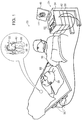
- FIG. 1 is a schematic, pictorial illustration of an intracardiac mapping system 20 that implements visualization of catheter-tissue contact by map distortion, in accordance with an embodiment of the present invention.
- System 20 comprises a probe 22, such as a catheter, and a control console 24.
- probe 22 is used for diagnostic or therapeutic treatment, such as for mapping electrical potentials in a heart 26 of a patient 28.
- probe 22 may be used, mutatis mutandis, for other therapeutic and/or diagnostic purposes in the heart or in other body organs.
- An operator 30 inserts probe 22 through the vascular system of patient 28 so that a distal end 32 of probe 22 enters a chamber of heart 26.
- System 20 typically uses magnetic position sensing to determine position coordinates of distal end 32 inside heart 26.
- Console 24 comprises a driver circuit 34, which drives field generators 36 placed at known positions external to patient 28, e.g., below the patient's torso.
- a magnetic field sensor 38 within distal end 32 of probe 22 (sensor 38 is shown in more detail in Figure 2 ) generates electrical signals in response to the magnetic fields from the coils, thereby enabling console 24 to determine the position of distal end 32 within the chamber.
- system 20 measures the position of distal end 32 using magnetic-based sensors
- other position tracking techniques may be used (e.g., impedance-based sensors).
- Magnetic position tracking techniques are described, for example, in U.S. Patents 5,391,199 , 5,443,489 , 6,788,967 , 6,690,963 , 5,558,091 , 6,172,499 6,177,792 , whose disclosures are incorporated herein by reference.
- Impedance-based position tracking techniques are described, for example, in U.S. Patents 5,983,126 , 6,456,864 and 5,944,022 .
- operator 30 positions distal end 32 at multiple positions on (or in close proximity to) the inner surface of the chamber.
- an electrode 40 coupled to the distal end measures a certain physiological property (e.g., the local surface electrical potential).
- System 20 correlates the position measurements and the electrical potential measurements.
- the system collects multiple map points, with each map point comprising a coordinate on the inner chamber surface and a respective physiological property measurement at this coordinate.
- Console 24 comprises a processor 42, which collects image data from a medical imaging system (not shown) such as a magnetic resonance imaging (MRI) system, or a computed tomography (CT) system, or a probe mapping system such as the CARTOTM mapping system produced by Biosense Webster Inc., of Diamond Bar, CA.
- MRI magnetic resonance imaging
- CT computed tomography
- probe mapping system such as the CARTOTM mapping system produced by Biosense Webster Inc., of Diamond Bar, CA.
- Processor 42 uses the image data to construct a simulated surface of the cardiac chamber in question. An example method for constructing the simulated surface is described further below.
- Processor 42 then "lays" the electrical potential measurements over the simulated surface produced from the image data.
- Processor 42 displays an image 44 of the simulated surface, with the electrical potential measurements laid thereon (the fusion of the simulated surface and the potential measurements is referred to herein as a map), to operator 30 on a display 46.
- Processor 42 typically comprises a general-purpose computer, with suitable front end and interface circuits for receiving signals from probe 22 and controlling the other components of console 24.
- Processor 42 may be programmed in software to carry out the functions that are described herein.
- the software may be downloaded to console 24 in electronic form, over a network, for example, or it may be provided on non-transitory tangible media, such as optical, magnetic or electronic memory media.
- some or all of the functions of processor 42 may be carried out by dedicated or programmable digital hardware components.
- processor 42 also monitors the signal measurements received from a force sensor 48 within distal end 32 (force sensor 48 is shown in more detail in Figure 2 ), in order to make an accurate evaluation of the force exerted by distal end 32 on endocardial tissue of heart 26.
- processor 42 may create a distorted surface in image 44 indicating the exerted force.
- Processor 42 stores data representing image 44 in a memory 50.
- operator 30 using one or more input devices 52 can control how processor 42 presents the distortion.
- image 44 comprises a three-dimensional representation of heart 26
- the operator can use input devices 52 to control the actual geometrical extent of a vertex representing the force exerted by the distal end. (Such a vertex may occur in a generally conical form if tissue tenting occurs.)
- operator 30 can use input devices 52 to control any coloring and/or shading used to indicate the exerted force.
- Figure 1 shows a particular system configuration
- other system configurations can also be employed to implement embodiments of the present invention, and are thus considered to be within the scope of the present inventions as defined by the claims.
- the methods described hereinbelow may be applied using position transducers of types other than the magnetic field sensor described above, such as impedance-based or ultrasonic position sensors.
- the term "position transducer" as used herein refers to an element mounted on probe 22 which causes console 24 to receive signals indicative of the coordinates of the distal end.
- the position transducer may thus comprise a receiver on the probe, which generates a position signal to the control unit based on energy received by the transducer; or it may comprise a transmitter, emitting energy that is sensed by a receiver external to the probe.
- the methods described hereinbelow may similarly be applied in therapeutic and diagnostic applications using not only catheters, but also probes of other types, both in the heart and in other body organs and regions.
- FIG. 2 is a schematic sectional view of distal end 32 of probe 22, in accordance with an embodiment of the present invention. Specifically, Figure 2 shows functional elements of distal end 32 used for therapeutic and/or diagnostic activity. Electrode 40 at a distal tip 60 of the probe senses electrical signals in the tissue. Electrode 40 is typically made of a metallic material, such as a platinum/iridium alloy or another suitable material. Alternatively, multiple electrodes (not shown) along the length of the probe may be provided.
- Position sensor 38 transmits a signal to console 24 that is indicative of the location coordinates of distal end 32.
- Position sensor 38 may comprise one or more miniature coils, and typically comprises multiple coils oriented along different axes.
- position sensor 38 may comprise either another type of magnetic sensor, an electrode that serves as a position transducer, or position transducers of other types, such as impedance-based or ultrasonic position sensors.
- Figure 2 shows a probe with a single position sensor, embodiments of the present invention may utilize probes with more than one position sensor.
- driver circuit 34 may drive a magnetic field generator in distal end 32 to generate one or more magnetic fields.
- the coils in generator 36 may be configured to sense the fields and generate signals indicative of the amplitudes of the components of these magnetic fields.
- Processor 42 receives and processes these signals in order to determine the position coordinates of distal end 32 within heart 26.
- Force sensor 48 measures a force applied by distal tip 60 to the endocardial tissue of heart 26 by generating a signal to the console that is indicative of the force exerted by the distal tip on the endocardial tissue.
- the force sensor may comprise a magnetic field transmitter and receiver connected by a spring in distal end 32, and may generate an indication of the force based on measuring the deflection of the spring. Further details of this sort of probe and force sensor are described in U.S. Patent Application Publications 2009/0093806 and 2009/0138007 .
- distal end 32 may comprise another type of force sensor.
- FIG. 3 is a block diagram that schematically illustrates elements of console 24, in accordance with a disclosed embodiment of the present invention.
- An intracardiac data acquisition module 70 collects force measurements and position signals from probe 22, and conveys the measurements and signals to a visualization module 72.
- An image acquisition module 74 collects image data for heart 26 (typically from an MRI or CT system, as described supra), and conveys the image data to module 72.
- Module 72 comprises interfaces 76 and 78 for communicating with modules 70 and 74, respectively.
- Processor 42 typically stores the collected image data to memory 50.
- Memory 50 may comprise any suitable volatile and/or non-volatile memory, such as random access memory or a hard disk drive.
- processor 42 applies an algorithm (e.g., a fast mapping process) to construct image 44.
- image 44 comprises a simulated 3D surface (e.g., a polygon mesh) of a surface of the cardiac chamber, which processor 42 presents as image 44 on display 46.
- processor 42 may distort image 44 in order to provide operator 30 with a visual representation of the force between distal end 32 and the endocardial tissue.
- examples of the distortion include, but are not limited to a vertex in the simulated surface, as well as coloring and/or shading of a region in the simulated surface corresponding to a location in heart 26 where distal end 32 is applying the force.
- Inputs from input devices 52 via an interface 58 enable operator 30 to adjust the visualization of the distortion. For example, operator 30 can determine how processor 42 presents the distortion on display 46. In other words, based on the operator input, the distortion shown on the simulated surface may not necessary reflect the actual distortion of the heart (e.g., the distortion may exaggerate the force).
- FIG 4 is an illustration of a simulated surface 90 showing distortion indicating catheter-tissue contact, in accordance with an embodiment of the present invention.
- simulated surface 90 represents a portion of a wall of heart 26 viewed from the outside of the heart.
- distal end 32 is pressing against endocardial tissue in heart 26, i.e., catheter 22 is within heart 26 and pressing against the heart wall.
- the distortion displayed in simulated surface 90 due to the force exerted by distal end 32 on the heart wall is displayed in a gray scale format as a protruding vertex 92, a dark portion 94, and a light portion 96, thus incorporating a 3D shadowed effect on the surface.
- simulated surface 90 may be visualized from inside heart 26, in which case the distortion may be displayed as a recessed vertex (i.e., a depression in surface 90 instead of protrusion 92).
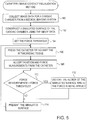
- FIG. 5 is a flow diagram that schematically illustrates a method of creating a distortion in map 44 in order to visualize catheter-tissue contact, in accordance with an embodiment of the present invention.
- processor 42 Prior to performing an intracardiac procedure, processor 42 collects image data for a chamber of heart 26 from a medical imaging system (e.g., a CARTOTM or an MRI or a CT imaging system), in a first collection step 100.
- the image data typically comprises data points representing tissue of the chamber.
- processor 42 applies an algorithm (e.g., a fast mapping process) to the collected image data in order to construct simulated surface 90.
- algorithm e.g., a fast mapping process
- a threshold set step 104 using input devices 52, operator 30 sets a predefined amount which defines a force threshold.
- the predefined amount may be defined in advance, and stored in memory 50.
- a positioning step 106 operator 30 positions probe 22 so that distal end 32 of the probe is pressing against endocardial tissue of heart 26.
- processor 42 accepts signals from position sensor 38 indicating a position measurement for distal end 32 within heart 26, and signals from force sensor 48 indicating a measurement of the force between distal end 32 and the endocardial tissue.
- a distortion step 112 processor 42 creates a distortion (e.g., protrusion 92) on simulated surface 90 at the location indicated by the position measurement, thereby forming a distorted surface.
- Operator 30 can control the magnitude of the distortion and/or the distortion type (e.g., a protrusion or coloring/shading) using input devices 52.
- processor 42 may adjust the magnitude of the distortion depending on the tissue in contact with distal end 32. For example, since an atrium of heart 26 has a thinner wall than a ventricle (of the heart), processor 42 may introduce a greater degree of distortion in map 44 when the distal end is in contact with atrial tissue (and applying an equivalent force).
- processor 42 presents map 44 which comprises the simulated surface (including any distortion) and relevant potential measurements on display 46, and the method returns to step 106 until operator 30 completes the intracardiac procedure.
- step 110 if the measured force is less than the force threshold, then the method continues with step 114, without introducing any distortion to simulated surface 90.
Description
- The present invention relates generally to medical imaging, and specifically to visualizing a force exerted by a medical probe on intra-body tissue.
- In electrophysiological diagnostic procedures such as intracardiac electrical mapping, an invasive medical probe is introduced into a cavity of a body organ. As the probe is positioned at specific points within the organ, the probe measures specific information (e.g., an electrical potential) and conveys the measurements to a mapping system. The mapping system creates a map comprising the measurements at their respective locations in the organ. The map can be used in applying various diagnostic and therapeutic procedures to the organ.
- When placing the probe within the organ, it may be desirable to have the distal tip of the probe in direct contact with organ tissue. The contact can be verified, for example, by measuring the contact pressure between the distal tip and the tissue.
U.S. Patent Application Publications 2007/0100332 ,2009/0093806 and2009/0138007 describe methods of sensing contact pressure between the distal tip of a catheter and tissue in a body cavity using a force sensor embedded in the catheter. - European patent publication
EP 2201890 A1 discloses a method for displaying information including displaying an icon on a display screen representing at least one probe parameter. - European patent publication
EP 2248480 A1 discloses overlaying a visualization of a contact point combined with force of a force sensing catheter on a 3D virtual model. - The present invention provides an apparatus and a computer software product as defined in the appended claims.
- There is also provided an apparatus including a probe and a processor. The probe is configured for insertion into a body cavity of a patient and includes a position sensor for measuring a position of a distal end of the probe inside the body cavity and a force sensor for measuring a force between the distal end and a wall of the body cavity. The processor is configured to construct a simulated surface of the body cavity, to accept from the probe, while pressing the distal end against the wall, position measurements indicating a position of the probe within the body cavity and force measurements indicating a force between the distal end and the wall, to create a distortion in the simulated surface at the position indicated by the position measurements, so as to form a distorted surface, upon detecting that the force measurements exceed a predefined amount, and to display the distorted surface.
- There is further provided a computer software product, operated in conjunction with a probe that is configured for insertion into a body cavity of a patient and includes a position sensor for measuring a position of a distal end of the probe inside the body cavity and a force sensor for measuring a force between the distal end and a wall of the body cavity, the product including a non-transitory computer-readable medium, in which program instructions are stored, which instructions, when read by a computer, cause the computer to construct a simulated surface of the body cavity, to accept from the probe, while pressing the distal end against the wall, position measurements indicating a position of the probe within the body cavity and force measurements indicating a force between the distal end and the wall, to create a distortion in the simulated surface at the position indicated by the position measurements, so as to form a distorted surface, upon detecting that the force measurements exceed a predefined amount, and to display the distorted surface.
- The disclosure is herein described, by way of example only, with reference to the accompanying drawings, wherein:
-
Figure 1 is a schematic pictorial illustration of a catheter-tissue contact visualization system for a force-sensing catheter, in accordance with an embodiment of the present invention; -
Figure 2 is a schematic side view showing details of the distal portion of the force-sensing catheter, in accordance with an embodiment of the present invention; -
Figure 3 is a block diagram that schematically illustrates elements of the catheter-tissue contact visualization system, in accordance with a disclosed embodiment of the present invention; -
Figure 4 is an illustration of a distortion indicating catheter-tissue contact, in accordance with an embodiment of the present invention; and -
Figure 5 is a flow diagram that schematically illustrates a method of visualizing catheter-tissue contact, in accordance with an embodiment of the present invention. - Physiological or anatomical mapping procedures typically create a map comprising map points collected from an electroanatomical mapping system. Each map point comprises a respective coordinate within a body organ, and possibly a physiological property collected by a medical probe at the respective coordinate.
- When collecting the map points, it is important to maintain the proper level of force between the probe and body cavity tissue, such as a heart wall. Sufficient force is needed in order to ensure good electrode contact between the probe and the tissue. Poor electrical contact can result in inaccurate readings. On the other hand, excessive force can deform the tissue and thus distort the map. In severe cases, too much force may cause physical damage to the heart wall.
- Embodiments of the present invention provide methods and systems for visualizing a contact force between a force-sensing probe such as an intracardiac catheter, and intra-body tissue such as a heart wall. In some embodiments, a simulated surface is constructed for the heart wall based on data points received from a medical imaging system. When the force-sensing probe applies a force to the heart wall, a distortion may be created on the simulated surface at the point of contact. The distortion may be presented graphically as a protruding vertex on the simulated surface corresponding to the location of the catheter-tissue contact, thereby presenting a three dimensional (3D) view of the heart wall to an operator such as a medical professional.
- When viewing the distortion from outside the heart chamber, the graphical effect of the distortion may be similar to the sort of protruding bump that is observed when a stick is pushed against an elastic cloth. Alternatively, the distortion may be visualized from the inside of the heart chamber as a vertex recessed in the simulated surface (i.e., a depression). In alternative embodiments, in a manner similar to hypsometric tinting and shaded relief methods that are used in cartography, the distortion may use coloring and/or shading to indicate the force between the catheter and the intra-body tissue, where different colors or shadings correspond to different force levels.
- The amount of distortion shown in the simulated surface may not necessary reflect the actual distortion of the heart wall resulting from the force. Embodiments of the present invention allow the operator to adjust the amount of distortion for visualization purposes. Additionally or alternatively, different relative degrees of distortion may be used under different circumstances. For example, greater distortion may be presented in atria than in ventricles (atria typically have thinner walls that ventricles), when the catheter applies a similar force.
- In some embodiments, the distortion indicating catheter-tissue contact may display not only the point of contact, but may also display the contact force, by increasing the distortion of the simulated surface in proportion to the force between the catheter and the intra-body tissue.
-
Figure 1 is a schematic, pictorial illustration of anintracardiac mapping system 20 that implements visualization of catheter-tissue contact by map distortion, in accordance with an embodiment of the present invention.System 20 comprises aprobe 22, such as a catheter, and acontrol console 24. In the embodiment described hereinbelow, it is assumed thatprobe 22 is used for diagnostic or therapeutic treatment, such as for mapping electrical potentials in aheart 26 of apatient 28. Alternatively,probe 22 may be used, mutatis mutandis, for other therapeutic and/or diagnostic purposes in the heart or in other body organs. - An
operator 30inserts probe 22 through the vascular system ofpatient 28 so that adistal end 32 ofprobe 22 enters a chamber ofheart 26.System 20 typically uses magnetic position sensing to determine position coordinates ofdistal end 32 insideheart 26.Console 24 comprises adriver circuit 34, which drivesfield generators 36 placed at known positions external topatient 28, e.g., below the patient's torso. Amagnetic field sensor 38 withindistal end 32 of probe 22 (sensor 38 is shown in more detail inFigure 2 ) generates electrical signals in response to the magnetic fields from the coils, thereby enablingconsole 24 to determine the position ofdistal end 32 within the chamber. - Although in the
present example system 20 measures the position ofdistal end 32 using magnetic-based sensors, other position tracking techniques may be used (e.g., impedance-based sensors). Magnetic position tracking techniques are described, for example, inU.S. Patents 5,391,199 ,5,443,489 ,6,788,967 ,6,690,963 ,5,558,091 ,6,172,499 6,177,792 , whose disclosures are incorporated herein by reference. Impedance-based position tracking techniques are described, for example, inU.S. Patents 5,983,126 ,6,456,864 and5,944,022 . - In order to map the cardiac chamber in question,
operator 30 positionsdistal end 32 at multiple positions on (or in close proximity to) the inner surface of the chamber. At each position, anelectrode 40 coupled to the distal end measures a certain physiological property (e.g., the local surface electrical potential).System 20 correlates the position measurements and the electrical potential measurements. Thus, the system collects multiple map points, with each map point comprising a coordinate on the inner chamber surface and a respective physiological property measurement at this coordinate. -
Console 24 comprises aprocessor 42, which collects image data from a medical imaging system (not shown) such as a magnetic resonance imaging (MRI) system, or a computed tomography (CT) system, or a probe mapping system such as the CARTO™ mapping system produced by Biosense Webster Inc., of Diamond Bar, CA.Processor 42 uses the image data to construct a simulated surface of the cardiac chamber in question. An example method for constructing the simulated surface is described further below.Processor 42 then "lays" the electrical potential measurements over the simulated surface produced from the image data.Processor 42 displays animage 44 of the simulated surface, with the electrical potential measurements laid thereon (the fusion of the simulated surface and the potential measurements is referred to herein as a map), tooperator 30 on adisplay 46. -
Processor 42 typically comprises a general-purpose computer, with suitable front end and interface circuits for receiving signals fromprobe 22 and controlling the other components ofconsole 24.Processor 42 may be programmed in software to carry out the functions that are described herein. The software may be downloaded to console 24 in electronic form, over a network, for example, or it may be provided on non-transitory tangible media, such as optical, magnetic or electronic memory media. Alternatively, some or all of the functions ofprocessor 42 may be carried out by dedicated or programmable digital hardware components. - In the present embodiment,
processor 42 also monitors the signal measurements received from aforce sensor 48 within distal end 32 (force sensor 48 is shown in more detail inFigure 2 ), in order to make an accurate evaluation of the force exerted bydistal end 32 on endocardial tissue ofheart 26. When the force exerted bydistal end 32 on the endocardial tissue exceeds a predefined amount,processor 42 may create a distorted surface inimage 44 indicating the exerted force. -
Processor 42 storesdata representing image 44 in amemory 50. In some embodiments,operator 30 using one ormore input devices 52, can control howprocessor 42 presents the distortion. For example, ifimage 44 comprises a three-dimensional representation ofheart 26, the operator can useinput devices 52 to control the actual geometrical extent of a vertex representing the force exerted by the distal end. (Such a vertex may occur in a generally conical form if tissue tenting occurs.) Additionally or alternatively,operator 30 can useinput devices 52 to control any coloring and/or shading used to indicate the exerted force. - Although
Figure 1 shows a particular system configuration, other system configurations can also be employed to implement embodiments of the present invention, and are thus considered to be within the scope of the present inventions as defined by the claims. For example, the methods described hereinbelow may be applied using position transducers of types other than the magnetic field sensor described above, such as impedance-based or ultrasonic position sensors. The term "position transducer" as used herein refers to an element mounted onprobe 22 which causesconsole 24 to receive signals indicative of the coordinates of the distal end. The position transducer may thus comprise a receiver on the probe, which generates a position signal to the control unit based on energy received by the transducer; or it may comprise a transmitter, emitting energy that is sensed by a receiver external to the probe. Furthermore, the methods described hereinbelow may similarly be applied in therapeutic and diagnostic applications using not only catheters, but also probes of other types, both in the heart and in other body organs and regions. -
Figure 2 is a schematic sectional view ofdistal end 32 ofprobe 22, in accordance with an embodiment of the present invention. Specifically,Figure 2 shows functional elements ofdistal end 32 used for therapeutic and/or diagnostic activity.Electrode 40 at adistal tip 60 of the probe senses electrical signals in the tissue.Electrode 40 is typically made of a metallic material, such as a platinum/iridium alloy or another suitable material. Alternatively, multiple electrodes (not shown) along the length of the probe may be provided. -
Position sensor 38 transmits a signal to console 24 that is indicative of the location coordinates ofdistal end 32.Position sensor 38 may comprise one or more miniature coils, and typically comprises multiple coils oriented along different axes. Alternatively,position sensor 38 may comprise either another type of magnetic sensor, an electrode that serves as a position transducer, or position transducers of other types, such as impedance-based or ultrasonic position sensors. AlthoughFigure 2 shows a probe with a single position sensor, embodiments of the present invention may utilize probes with more than one position sensor. - In an alternative embodiment, the roles of
position sensor 38 andmagnetic field generators 36 may be reversed. In other words,driver circuit 34 may drive a magnetic field generator indistal end 32 to generate one or more magnetic fields. The coils ingenerator 36 may be configured to sense the fields and generate signals indicative of the amplitudes of the components of these magnetic fields.Processor 42 receives and processes these signals in order to determine the position coordinates ofdistal end 32 withinheart 26. -
Force sensor 48 measures a force applied bydistal tip 60 to the endocardial tissue ofheart 26 by generating a signal to the console that is indicative of the force exerted by the distal tip on the endocardial tissue. In one embodiment, the force sensor may comprise a magnetic field transmitter and receiver connected by a spring indistal end 32, and may generate an indication of the force based on measuring the deflection of the spring. Further details of this sort of probe and force sensor are described inU.S. Patent Application Publications 2009/0093806 and2009/0138007 . Alternatively,distal end 32 may comprise another type of force sensor. -
Figure 3 is a block diagram that schematically illustrates elements ofconsole 24, in accordance with a disclosed embodiment of the present invention. An intracardiacdata acquisition module 70 collects force measurements and position signals fromprobe 22, and conveys the measurements and signals to a visualization module 72. Animage acquisition module 74 collects image data for heart 26 (typically from an MRI or CT system, as described supra), and conveys the image data to module 72. Module 72 comprisesinterfaces modules -
Processor 42 typically stores the collected image data tomemory 50.Memory 50 may comprise any suitable volatile and/or non-volatile memory, such as random access memory or a hard disk drive. After collecting the image data,processor 42 applies an algorithm (e.g., a fast mapping process) to constructimage 44. In the present embodiment,image 44 comprises a simulated 3D surface (e.g., a polygon mesh) of a surface of the cardiac chamber, whichprocessor 42 presents asimage 44 ondisplay 46. - If the collected force measurements exceed a predefined amount,
processor 42 may distortimage 44 in order to provideoperator 30 with a visual representation of the force betweendistal end 32 and the endocardial tissue. As discussed supra, examples of the distortion include, but are not limited to a vertex in the simulated surface, as well as coloring and/or shading of a region in the simulated surface corresponding to a location inheart 26 wheredistal end 32 is applying the force. - Inputs from
input devices 52 via an interface 58 enableoperator 30 to adjust the visualization of the distortion. For example,operator 30 can determine howprocessor 42 presents the distortion ondisplay 46. In other words, based on the operator input, the distortion shown on the simulated surface may not necessary reflect the actual distortion of the heart (e.g., the distortion may exaggerate the force). -
Figure 4 is an illustration of asimulated surface 90 showing distortion indicating catheter-tissue contact, in accordance with an embodiment of the present invention. In the example shown, simulatedsurface 90 represents a portion of a wall ofheart 26 viewed from the outside of the heart. In the example shown,distal end 32 is pressing against endocardial tissue inheart 26, i.e.,catheter 22 is withinheart 26 and pressing against the heart wall. The distortion displayed insimulated surface 90 due to the force exerted bydistal end 32 on the heart wall is displayed in a gray scale format as a protrudingvertex 92, adark portion 94, and alight portion 96, thus incorporating a 3D shadowed effect on the surface. Alternatively,simulated surface 90 may be visualized frominside heart 26, in which case the distortion may be displayed as a recessed vertex (i.e., a depression insurface 90 instead of protrusion 92). -
Figure 5 is a flow diagram that schematically illustrates a method of creating a distortion inmap 44 in order to visualize catheter-tissue contact, in accordance with an embodiment of the present invention. Prior to performing an intracardiac procedure,processor 42 collects image data for a chamber ofheart 26 from a medical imaging system (e.g., a CARTO™ or an MRI or a CT imaging system), in afirst collection step 100. The image data typically comprises data points representing tissue of the chamber. In aconstruction step 102,processor 42 applies an algorithm (e.g., a fast mapping process) to the collected image data in order to constructsimulated surface 90. - In a threshold set
step 104, usinginput devices 52,operator 30 sets a predefined amount which defines a force threshold. Alternatively, the predefined amount may be defined in advance, and stored inmemory 50. - During the intracardiac procedure, in a
positioning step 106,operator 30positions probe 22 so thatdistal end 32 of the probe is pressing against endocardial tissue ofheart 26. In asecond collection step 108,processor 42 accepts signals fromposition sensor 38 indicating a position measurement fordistal end 32 withinheart 26, and signals fromforce sensor 48 indicating a measurement of the force betweendistal end 32 and the endocardial tissue. - In a
comparison step 110, if the force measurement exceeds the force threshold, then in adistortion step 112,processor 42 creates a distortion (e.g., protrusion 92) onsimulated surface 90 at the location indicated by the position measurement, thereby forming a distorted surface.Operator 30 can control the magnitude of the distortion and/or the distortion type (e.g., a protrusion or coloring/shading) usinginput devices 52. Additionally,processor 42 may adjust the magnitude of the distortion depending on the tissue in contact withdistal end 32. For example, since an atrium ofheart 26 has a thinner wall than a ventricle (of the heart),processor 42 may introduce a greater degree of distortion inmap 44 when the distal end is in contact with atrial tissue (and applying an equivalent force). - In a
display step 114,processor 42 presents map 44 which comprises the simulated surface (including any distortion) and relevant potential measurements ondisplay 46, and the method returns to step 106 untiloperator 30 completes the intracardiac procedure. Returning to step 110, if the measured force is less than the force threshold, then the method continues withstep 114, without introducing any distortion tosimulated surface 90.
Claims (7)
- Apparatus, comprising:a probe (22), configured for insertion into a body cavity of a patient and comprising a position sensor (38) for measuring a position of a distal end (32) of the probe (22) inside the body cavity and a force sensor (48) for measuring a force between the distal end (32) and a wall of the body cavity; anda processor (42), which is configuredto construct a simulated surface (90) of the body cavity, to accept from the probe (22), while pressing the distal end (32) against the wall, position measurements indicating a position of the probe (22) within the body cavity and force measurements indicating a force between the distal end (32) and the wall,to create a distortion in the simulated surface (90) at the position indicated by the position measurements, so as to form a distorted surface, upon detecting that the force measurements exceed a predefined amount; andto display the distorted surface, characterised in that said distortion is created by incorporating a three dimensional effect on the simulated surface, wherein the three dimensional effect comprises a vertex protruding from the simulated surface, or a vertex recessing into the simulated surface.
- The apparatus according to claim 1, wherein the processor (42) is configured, at a time prior to constructing the simulated surface (90), to collect, from a medical imaging system, image data for the body cavity.
- The apparatus according to claim 2, wherein the medical imaging system is selected from a group consisting of a probe mapping system, a magnetic resonance imaging system and a computed tomography system.
- The apparatus according to claim 2, wherein the processor (42) is configured to construct the simulated surface (90) by applying a fast mapping process to the image data.
- The apparatus according to claim 1, wherein the probe (22) comprises an intracardiac catheter.
- The apparatus according to claim 1, wherein the processor (42) is further configured to create the distortion by filling a region of the simulated surface (90) with a specific color corresponding to the force at the position indicated by the position measurements.
- A computer software product, operated in conjunction with a probe (22) that is configured for insertion into a body cavity of a patient and includes a position sensor for measuring a position of a distal end (32) of the probe (22) inside the body cavity and a force sensor for measuring a force between the distal end (32) and a wall of the body cavity, the product comprising a non-transitory computer-readable medium, in which program instructions are stored, which instructions, when read by a computer, cause the computer to:construct a simulated surface (90) of the body cavity,accept from the probe (22), while pressing the distal end against the wall, position measurements indicating a position of the probe (22) within the body cavity and force measurements indicating a force between the distal end (32) and the wall,create a distortion in the simulated surface (90) at the position indicated by the position measurements, so as to form a distorted surface, upon detecting that the force measurements exceed a predefined amount; anddisplay the distorted surface, characterised in that said distortion is created by incorporating a three dimensional effect on the simulated surface, wherein the three dimensional effect comprises a vertex protruding from the simulated surface, or a vertex recessing into the simulated surface.
Priority Applications (1)
| Application Number | Priority Date | Filing Date | Title |
|---|---|---|---|
| EP19165295.7A EP3566646B1 (en) | 2010-11-04 | 2011-11-03 | Visualization of catheter-tissue contact by map distortion |
Applications Claiming Priority (1)
| Application Number | Priority Date | Filing Date | Title |
|---|---|---|---|
| US12/939,259 US8532738B2 (en) | 2010-11-04 | 2010-11-04 | Visualization of catheter-tissue contact by map distortion |
Related Child Applications (1)
| Application Number | Title | Priority Date | Filing Date |
|---|---|---|---|
| EP19165295.7A Division EP3566646B1 (en) | 2010-11-04 | 2011-11-03 | Visualization of catheter-tissue contact by map distortion |
Publications (2)
| Publication Number | Publication Date |
|---|---|
| EP2449962A1 EP2449962A1 (en) | 2012-05-09 |
| EP2449962B1 true EP2449962B1 (en) | 2019-03-27 |
Family
ID=44905651
Family Applications (2)
| Application Number | Title | Priority Date | Filing Date |
|---|---|---|---|
| EP11187708.0A Active EP2449962B1 (en) | 2010-11-04 | 2011-11-03 | Visualization of catheter-tissue contact by map distortion |
| EP19165295.7A Active EP3566646B1 (en) | 2010-11-04 | 2011-11-03 | Visualization of catheter-tissue contact by map distortion |
Family Applications After (1)
| Application Number | Title | Priority Date | Filing Date |
|---|---|---|---|
| EP19165295.7A Active EP3566646B1 (en) | 2010-11-04 | 2011-11-03 | Visualization of catheter-tissue contact by map distortion |
Country Status (8)
| Country | Link |
|---|---|
| US (1) | US8532738B2 (en) |
| EP (2) | EP2449962B1 (en) |
| JP (1) | JP5885999B2 (en) |
| CN (1) | CN102551667B (en) |
| AU (1) | AU2011239366B2 (en) |
| CA (1) | CA2756630C (en) |
| ES (1) | ES2727250T3 (en) |
| IL (1) | IL215746A (en) |
Families Citing this family (26)
| Publication number | Priority date | Publication date | Assignee | Title |
|---|---|---|---|---|
| US9713435B2 (en) * | 2011-07-27 | 2017-07-25 | Biosense Webster (Israel) Ltd. | Cardiac mapping using non-gated MRI |
| US9775578B2 (en) * | 2013-08-12 | 2017-10-03 | Biosense Webster (Israel) Ltd. | Unmapped region visualization |
| JP2017506969A (en) * | 2014-03-12 | 2017-03-16 | コーニンクレッカ フィリップス エヌ ヴェKoninklijke Philips N.V. | Tactile feedback system and method for transesophageal echocardiographic ultrasound transducer probe |
| USD761313S1 (en) | 2014-05-01 | 2016-07-12 | St. Jude Medical, Cardiology Division, Inc. | Display screen with a transitional graphical user interface |
| US20170215970A1 (en) | 2014-05-01 | 2017-08-03 | St. Jude Medical, Cardiology Division, Inc. | Depicting force |
| USD761808S1 (en) | 2014-05-01 | 2016-07-19 | St. Jude Medical, Cardiology Division, Inc. | Display screen with transitional graphical user interface |
| US9615764B2 (en) | 2014-11-03 | 2017-04-11 | Biosense Webster (Israel) Ltd | Real-time coloring of electrophysiological map |
| WO2016181317A2 (en) | 2015-05-12 | 2016-11-17 | Navix International Limited | Calculation of an ablation plan |
| US10507056B2 (en) | 2015-10-01 | 2019-12-17 | General Electric Company | System and method for representation and visualization of catheter applied force and power |
| EP3411113B1 (en) | 2016-02-04 | 2019-11-27 | Cardiac Pacemakers, Inc. | Delivery system with force sensor for leadless cardiac device |
| CN110177500B (en) * | 2016-11-16 | 2022-03-04 | 纳维斯国际有限公司 | Dynamic visual rendering of tissue models |
| WO2018092071A1 (en) | 2016-11-16 | 2018-05-24 | Navix International Limited | Estimators for ablation effectiveness |
| US10709507B2 (en) | 2016-11-16 | 2020-07-14 | Navix International Limited | Real-time display of treatment-related tissue changes using virtual material |
| WO2018092062A1 (en) | 2016-11-16 | 2018-05-24 | Navix International Limited | Real-time display of tissue deformation by interactions with an intra-body probe |
| US10510171B2 (en) | 2016-11-29 | 2019-12-17 | Biosense Webster (Israel) Ltd. | Visualization of anatomical cavities |
| US11653853B2 (en) | 2016-11-29 | 2023-05-23 | Biosense Webster (Israel) Ltd. | Visualization of distances to walls of anatomical cavities |
| JP2019017411A (en) * | 2017-07-11 | 2019-02-07 | 株式会社日立製作所 | Photoacoustic type catheter system and photoacoustic type catheter control method |
| US10864046B2 (en) * | 2017-12-04 | 2020-12-15 | Acclarent, Inc. | Dilation instrument with navigation and distally located force sensor |
| US10918310B2 (en) * | 2018-01-03 | 2021-02-16 | Biosense Webster (Israel) Ltd. | Fast anatomical mapping (FAM) using volume filling |
| IT201800007825A1 (en) * | 2018-08-03 | 2020-02-03 | St Europeo Di Oncologia Srl | ELECTRONIC SYSTEM AND PROBE FOR DETECTION OF TUMOR MASSES. |
| EP3677186A1 (en) | 2019-01-03 | 2020-07-08 | Siemens Healthcare GmbH | Medical imaging device, system, and method for generating a motion-compensated image, and corresponding storage medium |
| IL272254B2 (en) | 2019-02-15 | 2023-04-01 | Biosense Webster Israel Ltd | Transesophageal catheter with carbon dioxide delivery system for thermal protection of esophagus |
| US20210186601A1 (en) | 2019-12-23 | 2021-06-24 | Ethicon, Inc. | Transesophageal Catheter for Thermal Protection of the Esophagus |
| US20210187242A1 (en) | 2019-12-23 | 2021-06-24 | Ethicon, Inc. | Fluid Delivery System for Creating Separation Between Biological Surfaces |
| US20210186642A1 (en) | 2019-12-23 | 2021-06-24 | Ethicon, Inc. | Esophageal Protection Pathways |
| WO2022264011A1 (en) | 2021-06-14 | 2022-12-22 | Ethicon, Inc. | Catheter with carbon dioxide delivery system and methods |
Family Cites Families (31)
| Publication number | Priority date | Publication date | Assignee | Title |
|---|---|---|---|---|
| US5391199A (en) | 1993-07-20 | 1995-02-21 | Biosense, Inc. | Apparatus and method for treating cardiac arrhythmias |
| US5558091A (en) | 1993-10-06 | 1996-09-24 | Biosense, Inc. | Magnetic determination of position and orientation |
| US5876336A (en) | 1994-10-11 | 1999-03-02 | Ep Technologies, Inc. | Systems and methods for guiding movable electrode elements within multiple-electrode structure |
| US6690963B2 (en) | 1995-01-24 | 2004-02-10 | Biosense, Inc. | System for determining the location and orientation of an invasive medical instrument |
| US5697377A (en) | 1995-11-22 | 1997-12-16 | Medtronic, Inc. | Catheter mapping system and method |
| US6177792B1 (en) | 1996-03-26 | 2001-01-23 | Bisense, Inc. | Mutual induction correction for radiator coils of an objects tracking system |
| US5944022A (en) | 1997-04-28 | 1999-08-31 | American Cardiac Ablation Co. Inc. | Catheter positioning system |
| US6490474B1 (en) * | 1997-08-01 | 2002-12-03 | Cardiac Pathways Corporation | System and method for electrode localization using ultrasound |
| WO1999017265A1 (en) * | 1997-09-26 | 1999-04-08 | Boston Dynamics, Inc. | Method and apparatus for surgical training and simulating surgery |
| US6810281B2 (en) | 2000-12-21 | 2004-10-26 | Endovia Medical, Inc. | Medical mapping system |
| US6298257B1 (en) * | 1999-09-22 | 2001-10-02 | Sterotaxis, Inc. | Cardiac methods and system |
| US6172499B1 (en) | 1999-10-29 | 2001-01-09 | Ascension Technology Corporation | Eddy current error-reduced AC magnetic position measurement system |
| US6892091B1 (en) * | 2000-02-18 | 2005-05-10 | Biosense, Inc. | Catheter, method and apparatus for generating an electrical map of a chamber of the heart |
| US7632265B2 (en) * | 2004-05-28 | 2009-12-15 | St. Jude Medical, Atrial Fibrillation Division, Inc. | Radio frequency ablation servo catheter and method |
| US10258285B2 (en) * | 2004-05-28 | 2019-04-16 | St. Jude Medical, Atrial Fibrillation Division, Inc. | Robotic surgical system and method for automated creation of ablation lesions |
| US8075498B2 (en) | 2005-03-04 | 2011-12-13 | Endosense Sa | Medical apparatus system having optical fiber load sensing capability |
| US20070062546A1 (en) | 2005-06-02 | 2007-03-22 | Viswanathan Raju R | Electrophysiology catheter and system for gentle and firm wall contact |
| AU2006305967B2 (en) | 2005-10-27 | 2013-02-07 | St. Jude Medical, Atrial Fibrillation Division, Inc. | Systems and methods for electrode contact assessment |
| US8403925B2 (en) | 2006-12-06 | 2013-03-26 | St. Jude Medical, Atrial Fibrillation Division, Inc. | System and method for assessing lesions in tissue |
| EP1986563B1 (en) | 2006-02-22 | 2012-12-26 | Hansen Medical, Inc. | System and apparatus for measuring distal forces on a working instrument |
| US8048063B2 (en) | 2006-06-09 | 2011-11-01 | Endosense Sa | Catheter having tri-axial force sensor |
| US20090076476A1 (en) | 2007-08-15 | 2009-03-19 | Hansen Medical, Inc. | Systems and methods employing force sensing for mapping intra-body tissue |
| US8131379B2 (en) | 2007-08-27 | 2012-03-06 | St. Jude Medical Atrial Fibrillation Division, Inc. | Cardiac tissue elasticity sensing |
| US8535308B2 (en) | 2007-10-08 | 2013-09-17 | Biosense Webster (Israel), Ltd. | High-sensitivity pressure-sensing probe |
| US8357152B2 (en) | 2007-10-08 | 2013-01-22 | Biosense Webster (Israel), Ltd. | Catheter with pressure sensing |
| US8340379B2 (en) * | 2008-03-07 | 2012-12-25 | Inneroptic Technology, Inc. | Systems and methods for displaying guidance data based on updated deformable imaging data |
| US8532734B2 (en) | 2008-04-18 | 2013-09-10 | Regents Of The University Of Minnesota | Method and apparatus for mapping a structure |
| US9326700B2 (en) | 2008-12-23 | 2016-05-03 | Biosense Webster (Israel) Ltd. | Catheter display showing tip angle and pressure |
| US8594841B2 (en) | 2008-12-31 | 2013-11-26 | Intuitive Surgical Operations, Inc. | Visual force feedback in a minimally invasive surgical procedure |
| CA2703347C (en) * | 2009-05-08 | 2016-10-04 | Endosense Sa | Method and apparatus for controlling lesion size in catheter-based ablation treatment |
| US8311791B1 (en) * | 2009-10-19 | 2012-11-13 | Surgical Theater LLC | Method and system for simulating surgical procedures |
-
2010
- 2010-11-04 US US12/939,259 patent/US8532738B2/en active Active
-
2011
- 2011-10-23 IL IL215746A patent/IL215746A/en active IP Right Grant
- 2011-10-27 AU AU2011239366A patent/AU2011239366B2/en active Active
- 2011-11-01 CA CA2756630A patent/CA2756630C/en active Active
- 2011-11-02 JP JP2011240962A patent/JP5885999B2/en active Active
- 2011-11-03 EP EP11187708.0A patent/EP2449962B1/en active Active
- 2011-11-03 ES ES11187708T patent/ES2727250T3/en active Active
- 2011-11-03 EP EP19165295.7A patent/EP3566646B1/en active Active
- 2011-11-04 CN CN201110372686.3A patent/CN102551667B/en active Active
Non-Patent Citations (1)
| Title |
|---|
| None * |
Also Published As
| Publication number | Publication date |
|---|---|
| CA2756630C (en) | 2020-01-14 |
| JP2012096037A (en) | 2012-05-24 |
| IL215746A (en) | 2014-08-31 |
| CA2756630A1 (en) | 2012-05-04 |
| JP5885999B2 (en) | 2016-03-16 |
| CN102551667A (en) | 2012-07-11 |
| EP3566646A1 (en) | 2019-11-13 |
| IL215746A0 (en) | 2011-12-29 |
| EP3566646B1 (en) | 2022-10-12 |
| AU2011239366A1 (en) | 2012-05-24 |
| US20120116210A1 (en) | 2012-05-10 |
| ES2727250T3 (en) | 2019-10-15 |
| EP2449962A1 (en) | 2012-05-09 |
| CN102551667B (en) | 2015-12-16 |
| AU2011239366B2 (en) | 2014-09-18 |
| US8532738B2 (en) | 2013-09-10 |
Similar Documents
| Publication | Publication Date | Title |
|---|---|---|
| EP2449962B1 (en) | Visualization of catheter-tissue contact by map distortion | |
| EP2837328B1 (en) | Unmapped region visualization | |
| AU2014268214B2 (en) | Dynamic mapping point filtering using a pre-acquired image | |
| EP2901922B1 (en) | Enhanced ecg chart presentation | |
| US20130241929A1 (en) | Selectably transparent electrophysiology map | |
| CA2833518A1 (en) | Using location and force measurements to estimate tissue thickness | |
| CN112617842A (en) | 3D intracardiac activity demonstration |
Legal Events
| Date | Code | Title | Description |
|---|---|---|---|
| PUAI | Public reference made under article 153(3) epc to a published international application that has entered the european phase |
Free format text: ORIGINAL CODE: 0009012 |
|
| AK | Designated contracting states |
Kind code of ref document: A1 Designated state(s): AL AT BE BG CH CY CZ DE DK EE ES FI FR GB GR HR HU IE IS IT LI LT LU LV MC MK MT NL NO PL PT RO RS SE SI SK SM TR |
|
| AX | Request for extension of the european patent |
Extension state: BA ME |
|
| 17P | Request for examination filed |
Effective date: 20121025 |
|
| STAA | Information on the status of an ep patent application or granted ep patent |
Free format text: STATUS: EXAMINATION IS IN PROGRESS |
|
| 17Q | First examination report despatched |
Effective date: 20170807 |
|
| GRAP | Despatch of communication of intention to grant a patent |
Free format text: ORIGINAL CODE: EPIDOSNIGR1 |
|
| STAA | Information on the status of an ep patent application or granted ep patent |
Free format text: STATUS: GRANT OF PATENT IS INTENDED |
|
| INTG | Intention to grant announced |
Effective date: 20181005 |
|
| GRAS | Grant fee paid |
Free format text: ORIGINAL CODE: EPIDOSNIGR3 |
|
| GRAA | (expected) grant |
Free format text: ORIGINAL CODE: 0009210 |
|
| STAA | Information on the status of an ep patent application or granted ep patent |
Free format text: STATUS: THE PATENT HAS BEEN GRANTED |
|
| RAP1 | Party data changed (applicant data changed or rights of an application transferred) |
Owner name: BIOSENSE WEBSTER (ISRAEL) LTD. |
|
| AK | Designated contracting states |
Kind code of ref document: B1 Designated state(s): AL AT BE BG CH CY CZ DE DK EE ES FI FR GB GR HR HU IE IS IT LI LT LU LV MC MK MT NL NO PL PT RO RS SE SI SK SM TR |
|
| REG | Reference to a national code |
Ref country code: GB Ref legal event code: FG4D |
|
| REG | Reference to a national code |
Ref country code: CH Ref legal event code: EP |
|
| REG | Reference to a national code |
Ref country code: AT Ref legal event code: REF Ref document number: 1112023 Country of ref document: AT Kind code of ref document: T Effective date: 20190415 |
|
| REG | Reference to a national code |
Ref country code: IE Ref legal event code: FG4D |
|
| REG | Reference to a national code |
Ref country code: DE Ref legal event code: R096 Ref document number: 602011057476 Country of ref document: DE |
|
| REG | Reference to a national code |
Ref country code: NL Ref legal event code: FP |
|
| PG25 | Lapsed in a contracting state [announced via postgrant information from national office to epo] |
Ref country code: FI Free format text: LAPSE BECAUSE OF FAILURE TO SUBMIT A TRANSLATION OF THE DESCRIPTION OR TO PAY THE FEE WITHIN THE PRESCRIBED TIME-LIMIT Effective date: 20190327 Ref country code: NO Free format text: LAPSE BECAUSE OF FAILURE TO SUBMIT A TRANSLATION OF THE DESCRIPTION OR TO PAY THE FEE WITHIN THE PRESCRIBED TIME-LIMIT Effective date: 20190627 Ref country code: SE Free format text: LAPSE BECAUSE OF FAILURE TO SUBMIT A TRANSLATION OF THE DESCRIPTION OR TO PAY THE FEE WITHIN THE PRESCRIBED TIME-LIMIT Effective date: 20190327 Ref country code: LT Free format text: LAPSE BECAUSE OF FAILURE TO SUBMIT A TRANSLATION OF THE DESCRIPTION OR TO PAY THE FEE WITHIN THE PRESCRIBED TIME-LIMIT Effective date: 20190327 |
|
| PG25 | Lapsed in a contracting state [announced via postgrant information from national office to epo] |
Ref country code: HR Free format text: LAPSE BECAUSE OF FAILURE TO SUBMIT A TRANSLATION OF THE DESCRIPTION OR TO PAY THE FEE WITHIN THE PRESCRIBED TIME-LIMIT Effective date: 20190327 Ref country code: GR Free format text: LAPSE BECAUSE OF FAILURE TO SUBMIT A TRANSLATION OF THE DESCRIPTION OR TO PAY THE FEE WITHIN THE PRESCRIBED TIME-LIMIT Effective date: 20190628 Ref country code: BG Free format text: LAPSE BECAUSE OF FAILURE TO SUBMIT A TRANSLATION OF THE DESCRIPTION OR TO PAY THE FEE WITHIN THE PRESCRIBED TIME-LIMIT Effective date: 20190627 Ref country code: LV Free format text: LAPSE BECAUSE OF FAILURE TO SUBMIT A TRANSLATION OF THE DESCRIPTION OR TO PAY THE FEE WITHIN THE PRESCRIBED TIME-LIMIT Effective date: 20190327 Ref country code: RS Free format text: LAPSE BECAUSE OF FAILURE TO SUBMIT A TRANSLATION OF THE DESCRIPTION OR TO PAY THE FEE WITHIN THE PRESCRIBED TIME-LIMIT Effective date: 20190327 |
|
| REG | Reference to a national code |
Ref country code: AT Ref legal event code: MK05 Ref document number: 1112023 Country of ref document: AT Kind code of ref document: T Effective date: 20190327 |
|
| REG | Reference to a national code |
Ref country code: ES Ref legal event code: FG2A Ref document number: 2727250 Country of ref document: ES Kind code of ref document: T3 Effective date: 20191015 |
|
| PG25 | Lapsed in a contracting state [announced via postgrant information from national office to epo] |
Ref country code: SK Free format text: LAPSE BECAUSE OF FAILURE TO SUBMIT A TRANSLATION OF THE DESCRIPTION OR TO PAY THE FEE WITHIN THE PRESCRIBED TIME-LIMIT Effective date: 20190327 Ref country code: RO Free format text: LAPSE BECAUSE OF FAILURE TO SUBMIT A TRANSLATION OF THE DESCRIPTION OR TO PAY THE FEE WITHIN THE PRESCRIBED TIME-LIMIT Effective date: 20190327 Ref country code: EE Free format text: LAPSE BECAUSE OF FAILURE TO SUBMIT A TRANSLATION OF THE DESCRIPTION OR TO PAY THE FEE WITHIN THE PRESCRIBED TIME-LIMIT Effective date: 20190327 Ref country code: AL Free format text: LAPSE BECAUSE OF FAILURE TO SUBMIT A TRANSLATION OF THE DESCRIPTION OR TO PAY THE FEE WITHIN THE PRESCRIBED TIME-LIMIT Effective date: 20190327 Ref country code: PT Free format text: LAPSE BECAUSE OF FAILURE TO SUBMIT A TRANSLATION OF THE DESCRIPTION OR TO PAY THE FEE WITHIN THE PRESCRIBED TIME-LIMIT Effective date: 20190727 Ref country code: CZ Free format text: LAPSE BECAUSE OF FAILURE TO SUBMIT A TRANSLATION OF THE DESCRIPTION OR TO PAY THE FEE WITHIN THE PRESCRIBED TIME-LIMIT Effective date: 20190327 |
|
| PG25 | Lapsed in a contracting state [announced via postgrant information from national office to epo] |
Ref country code: PL Free format text: LAPSE BECAUSE OF FAILURE TO SUBMIT A TRANSLATION OF THE DESCRIPTION OR TO PAY THE FEE WITHIN THE PRESCRIBED TIME-LIMIT Effective date: 20190327 Ref country code: SM Free format text: LAPSE BECAUSE OF FAILURE TO SUBMIT A TRANSLATION OF THE DESCRIPTION OR TO PAY THE FEE WITHIN THE PRESCRIBED TIME-LIMIT Effective date: 20190327 |
|
| PG25 | Lapsed in a contracting state [announced via postgrant information from national office to epo] |
Ref country code: AT Free format text: LAPSE BECAUSE OF FAILURE TO SUBMIT A TRANSLATION OF THE DESCRIPTION OR TO PAY THE FEE WITHIN THE PRESCRIBED TIME-LIMIT Effective date: 20190327 Ref country code: IS Free format text: LAPSE BECAUSE OF FAILURE TO SUBMIT A TRANSLATION OF THE DESCRIPTION OR TO PAY THE FEE WITHIN THE PRESCRIBED TIME-LIMIT Effective date: 20190727 |
|
| REG | Reference to a national code |
Ref country code: DE Ref legal event code: R097 Ref document number: 602011057476 Country of ref document: DE |
|
| PG25 | Lapsed in a contracting state [announced via postgrant information from national office to epo] |
Ref country code: DK Free format text: LAPSE BECAUSE OF FAILURE TO SUBMIT A TRANSLATION OF THE DESCRIPTION OR TO PAY THE FEE WITHIN THE PRESCRIBED TIME-LIMIT Effective date: 20190327 |
|
| PLBE | No opposition filed within time limit |
Free format text: ORIGINAL CODE: 0009261 |
|
| STAA | Information on the status of an ep patent application or granted ep patent |
Free format text: STATUS: NO OPPOSITION FILED WITHIN TIME LIMIT |
|
| PG25 | Lapsed in a contracting state [announced via postgrant information from national office to epo] |
Ref country code: SI Free format text: LAPSE BECAUSE OF FAILURE TO SUBMIT A TRANSLATION OF THE DESCRIPTION OR TO PAY THE FEE WITHIN THE PRESCRIBED TIME-LIMIT Effective date: 20190327 |
|
| PGFP | Annual fee paid to national office [announced via postgrant information from national office to epo] |
Ref country code: BE Payment date: 20191017 Year of fee payment: 9 |
|
| 26N | No opposition filed |
Effective date: 20200103 |
|
| PG25 | Lapsed in a contracting state [announced via postgrant information from national office to epo] |
Ref country code: TR Free format text: LAPSE BECAUSE OF FAILURE TO SUBMIT A TRANSLATION OF THE DESCRIPTION OR TO PAY THE FEE WITHIN THE PRESCRIBED TIME-LIMIT Effective date: 20190327 |
|
| PGFP | Annual fee paid to national office [announced via postgrant information from national office to epo] |
Ref country code: CH Payment date: 20191116 Year of fee payment: 9 |
|
| PG25 | Lapsed in a contracting state [announced via postgrant information from national office to epo] |
Ref country code: MC Free format text: LAPSE BECAUSE OF FAILURE TO SUBMIT A TRANSLATION OF THE DESCRIPTION OR TO PAY THE FEE WITHIN THE PRESCRIBED TIME-LIMIT Effective date: 20190327 Ref country code: LU Free format text: LAPSE BECAUSE OF NON-PAYMENT OF DUE FEES Effective date: 20191103 |
|
| REG | Reference to a national code |
Ref country code: DE Ref legal event code: R079 Ref document number: 602011057476 Country of ref document: DE Free format text: PREVIOUS MAIN CLASS: A61B0005042000 Ipc: A61B0005283000 |
|
| REG | Reference to a national code |
Ref country code: ES Ref legal event code: FD2A Effective date: 20210527 |
|
| PG25 | Lapsed in a contracting state [announced via postgrant information from national office to epo] |
Ref country code: CY Free format text: LAPSE BECAUSE OF FAILURE TO SUBMIT A TRANSLATION OF THE DESCRIPTION OR TO PAY THE FEE WITHIN THE PRESCRIBED TIME-LIMIT Effective date: 20190327 |
|
| REG | Reference to a national code |
Ref country code: CH Ref legal event code: PL |
|
| PG25 | Lapsed in a contracting state [announced via postgrant information from national office to epo] |
Ref country code: HU Free format text: LAPSE BECAUSE OF FAILURE TO SUBMIT A TRANSLATION OF THE DESCRIPTION OR TO PAY THE FEE WITHIN THE PRESCRIBED TIME-LIMIT; INVALID AB INITIO Effective date: 20111103 Ref country code: MT Free format text: LAPSE BECAUSE OF FAILURE TO SUBMIT A TRANSLATION OF THE DESCRIPTION OR TO PAY THE FEE WITHIN THE PRESCRIBED TIME-LIMIT Effective date: 20190327 |
|
| REG | Reference to a national code |
Ref country code: BE Ref legal event code: MM Effective date: 20201130 |
|
| PG25 | Lapsed in a contracting state [announced via postgrant information from national office to epo] |
Ref country code: LI Free format text: LAPSE BECAUSE OF NON-PAYMENT OF DUE FEES Effective date: 20201130 Ref country code: ES Free format text: LAPSE BECAUSE OF NON-PAYMENT OF DUE FEES Effective date: 20191104 Ref country code: CH Free format text: LAPSE BECAUSE OF NON-PAYMENT OF DUE FEES Effective date: 20201130 |
|
| PG25 | Lapsed in a contracting state [announced via postgrant information from national office to epo] |
Ref country code: MK Free format text: LAPSE BECAUSE OF FAILURE TO SUBMIT A TRANSLATION OF THE DESCRIPTION OR TO PAY THE FEE WITHIN THE PRESCRIBED TIME-LIMIT Effective date: 20190327 |
|
| PG25 | Lapsed in a contracting state [announced via postgrant information from national office to epo] |
Ref country code: BE Free format text: LAPSE BECAUSE OF NON-PAYMENT OF DUE FEES Effective date: 20201130 |
|
| PGFP | Annual fee paid to national office [announced via postgrant information from national office to epo] |
Ref country code: NL Payment date: 20221019 Year of fee payment: 12 |
|
| PGFP | Annual fee paid to national office [announced via postgrant information from national office to epo] |
Ref country code: GB Payment date: 20230928 Year of fee payment: 13 |
|
| PGFP | Annual fee paid to national office [announced via postgrant information from national office to epo] |
Ref country code: FR Payment date: 20230929 Year of fee payment: 13 |
|
| PGFP | Annual fee paid to national office [announced via postgrant information from national office to epo] |
Ref country code: IT Payment date: 20231010 Year of fee payment: 13 Ref country code: IE Payment date: 20231009 Year of fee payment: 13 Ref country code: DE Payment date: 20230929 Year of fee payment: 13 |