EP2448809B1 - Track system - Google Patents
Track system Download PDFInfo
- Publication number
- EP2448809B1 EP2448809B1 EP10793470.5A EP10793470A EP2448809B1 EP 2448809 B1 EP2448809 B1 EP 2448809B1 EP 10793470 A EP10793470 A EP 10793470A EP 2448809 B1 EP2448809 B1 EP 2448809B1
- Authority
- EP
- European Patent Office
- Prior art keywords
- track system
- sprocket wheel
- rotation axis
- vehicle
- support frame
- Prior art date
- Legal status (The legal status is an assumption and is not a legal conclusion. Google has not performed a legal analysis and makes no representation as to the accuracy of the status listed.)
- Active
Links
Images



Classifications
-
- B—PERFORMING OPERATIONS; TRANSPORTING
- B62—LAND VEHICLES FOR TRAVELLING OTHERWISE THAN ON RAILS
- B62D—MOTOR VEHICLES; TRAILERS
- B62D55/00—Endless track vehicles
- B62D55/04—Endless track vehicles with tracks and alternative ground wheels, e.g. changeable from endless track vehicle into wheeled vehicle and vice versa
-
- B—PERFORMING OPERATIONS; TRANSPORTING
- B62—LAND VEHICLES FOR TRAVELLING OTHERWISE THAN ON RAILS
- B62D—MOTOR VEHICLES; TRAILERS
- B62D55/00—Endless track vehicles
- B62D55/08—Endless track units; Parts thereof
- B62D55/084—Endless-track units or carriages mounted separably, adjustably or extensibly on vehicles, e.g. portable track units
Definitions
- the present invention generally relates to track systems used as wheel replacements on normally wheeled vehicles. More particularly, but in no limitative fashion, the present invention relates to track systems for replacing wheels on heavy vehicles such as, but not limited to, construction, industrial, forestry, agricultural and farming vehicles.
- Traction and flotation have always been important issues with farming and construction vehicles. Having a vehicle mounted on track systems assures lower ground pressure, better traction and better use of the available power. This is particularly important when the vehicle is operated on soft ground condition or when increased traction effort is required.
- One of the challenges when fitting a track system in replacement of a wheel is to fit the track system within the available space envelope of the former wheel.
- Typical track systems which feature a pivoting motion, tend to interfere with surroundings equipments such as fenders, fuel or oil tanks, vehicle chassis, three point hitches, etc.
- the present invention therefore provides a solution to the shortcomings of the prior art by providing a track system which movements are limited such as to prevent interference with the vehicle and its accessories.
- the track system generally comprises a sprocket wheel configured to be mounted to one of the wheel axles or wheel hubs of the vehicle, a support frame connected to the sprocket wheel via a support member pivotally mounted to both the sprocket wheel and the support frame, and a longitudinally extending endless traction band or track mounted thereabout.
- the support frame typically pivotally supports wheels such as idlers wheels mounted at the fore and at the aft, and road wheels mounted along the length thereof.
- the track system is further provided with a movement limiting link mounted to the support member and configured to be mounted to the vehicle frame.
- the movement limiting link limits the movements of the track system, such as to prevent contacts between the track system and the vehicle.
- the link allows the support frame to pivot with respect to the support member but prevents longitudinal movements (i.e. forward and/or rearward movements) and lateral movements (i.e. side movements) of the support frame relatively to the support member.
- the track system is preferably adaptable to a plurality of vehicle sizes; indeed, the length and configuration of the link may be adapted and/or modified.
- the link comprises two sections that may be screwed or unscrewed to modify the configuration of the link.
- the first end and the second end of the link may be connected at different places on the support member and/or on the frame of the vehicle to adapt the track system to a particular vehicle or to change the configuration of a vehicle.
- the present invention is particularly useful for track systems used on farming and generally agricultural vehicles, the present invention could also be used on vehicles used in other industries such as in the construction industry, or in the forestry industry.
- Figure 1 is an elevation view of the exterior or outer side of an exemplary track system in accordance with the present invention.
- Figure 2 is an elevation view of the interior or inner side of the track system of Fig. 1 , without the traction band.
- Figure 3 is a perspective view of the interior side of the track system of Fig. 1 .
- Figure 3A an enlarged detailed view of the encircled section identified as A in Fig.3 .
- Figure 4 is another perspective view of the interior side of the track system of Fig. 1 , without the traction band.
- Figure 4A is an enlarged detailed view of the encircled section identified as B in Fig. 4 .
- Figure 5 is a perspective view of the exterior side of the track system of Fig. 1 , without the traction band.
- Figure 6 is a perspective view of the interior side of the track system of Fig. 1 , without the traction band.
- Figure 7 is a perspective view of the interior side of the track system of Fig. 1 , without the traction band and mounted to the axle/hub of a partially shown vehicle.
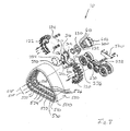
- Figure 8 is an exploded view of the track system shown in Fig. 1 .
- Figure 9 is perspective and partially exploded view of the interior side of the track system of Fig. 1 , showing a portion of the vehicle axle/hub and frame.
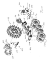
- Figure 10 is another exploded view of the track system shown in Fig. 1 , without the traction band.
- the track system 10 typically comprises a sprocket wheel 100 configured to be mounted to the wheel axle or hub 600 (see Figs. 8 and 10 ) of a vehicle (not shown), a support frame 200, a support member 300 pivotally connected to both the sprocket wheel 100 and the support frame 200, a movement limiting link 400 connected to support member 300, and an endless traction band 500 disposed around the sprocket wheel 100 and the support frame 200.
- the sprocket wheel 100 generally comprises a plurality of generally evenly spaced sprocket teeth 110 located at the periphery thereof.
- the sprocket teeth 110 are configured to drivingly engage the drive lugs 534 of the traction band 500 which will be described in more details below (see Fig. 8 ).
- the sprocket wheel 100 is comprised of two generally semi-circular sections 120 and 122 which are configured to be mounted together via attaching plates 124 and 126 and appropriate fasteners such as bolts and nuts.
- the sprocket wheel 100 further comprises a circular disk 130 having formed therein first circularly disposed apertures 132 configured to reflect the bolt pattern of the vehicle axle/hub 600 such as to receive the mounting bolts 610 thereof (see particularly Figs. 8 and 10 ), and second circularly disposed apertures 134 configured to receive the fastening bolts of the sprocket wheel 100 and of the flange 316 of the shaft 312 which will be described in more details below.
- the two sections 120 and 122 of the sprocket wheel 100 could be unitary or the sprocket wheel 100 could have more than two sections 120 and 122.
- the disk 130 could be unitary with the sprocket wheel 100 or could even be omitted if, for example, the configuration of the vehicle axle/hub 600 and/or the configuration of the sprocket wheel 100 allows for a direct bolting of the shaft 312 to the sprocket wheel 100.
- the support frame 200 is generally configured as a generally longitudinally extending structure having pivotally mounted thereto a plurality of wheels such as idler wheels 210 respectively mounted at the front end 202 and at the rear end 204 of the support frame 200, and road wheels 220 mounted along the length of the middle portion 203 of the support frame 200 between the front and rear idler wheels 210.
- the idler wheels 210 and the road wheels 220 are mounted on either sides of the support frame 200 via cantilevered shafts 212 (for the idler wheels 210) and shafts 222 (for the road wheels 220).
- the wheels 210 and 220 could be mounted to axles pivotally mounted within the support frame 200. Still, other configurations are possible.
- the support frame 200 is further provided with a transverse opening 230 extending laterally through the support frame 200 and configured to pivotally receive the lower shaft 352 of the support member 300 and one or more bearings and seals assembly 232.
- the opening 230 is substantially centrally located with respect to the length of the support frame 200. Still, in some other embodiments, the opening 230 could be located nearer the front end 202 or nearer the rear end 204.
- FIG. 1 , 2 , 5 , 6 , 8 and 10 the support member 300 is shown in more details.
- the support member 300 is generally configured as a generally vertically extending structure which generally comprises an upper portion 310, a middle or intermediate portion 330, and a lower portion 350.
- the support member 300 also comprises a back member or plate 370, best shown in Figs. 2 and 6 , secured to the middle portion 330 and lower portion 350.
- the upper portion 310 is configured to be pivotally, yet not drivingly, engaged to the sprocket wheel 100.
- the upper portion 310 comprises a shaft 312 pivotally mounted within a transverse opening 314 (best shown in Fig. 10 ), via an assembly of bearings or rollers.
- the shaft 312 comprises, at its extremity adjacent to the sprocket wheel 100, a radially extending flange 316 configured to be secured to the disk 130 of the sprocket wheel 100 as explained above.
- the flange 316 is provided with apertures 317 matching some or all of the apertures 134 of the disk 130. Understandably, in some other embodiments, the flange 316 could be directly mounted to the sprocket wheel 100 without the need for a disk 130.
- the middle portion 330 of the support member 300 comprises a front or forward projection 332 and a rear or rearward projection 334.
- the front projection 332 comprises, at its extremity, a front arm 336 (best shown in Figs. 6 and 8 ), and, similarly, the rear projection 334 comprises, at its extremity, a rear arm 338 (best shown in Fig. 5 ).
- the front and rear arms 336 and 338 extend laterally toward the inner side of the track system 10.
- front and rear arms 336 and 338 are substantially parallel.
- the front and rear arms 336 and 338 serve two purposes.
- the front and rear arms 336 and 338 act as stoppers for limiting the rotating movement of the support frame 200 about the rotation axis 353 (see Figs. 5 and 6 ) of the shaft 352.
- the support frame 200 pivots about the axis 353
- upward movements of the front end 202 or of the rear end 204 will be limited or stopped by either one of the front and rear arms 336 and 338.
- front and rear elastomeric stoppers 206 and 208 are preferably provided on the top surface of the support frame 200 as shown in Figs. 1 , 8 and 10 .
- the front and rear arms 336 and 338 rigidly link the middle portion 330 of the support member 300 to the back plate 370.
- the back plate 370 is preferably bolted to the front and rear arms 336 and 338.
- the movement limiting link 400 is connected to both the back plate 370 and the vehicle such as to prevent movement of the support member 300.
- the back plate 370 could be embodied by other functionally equivalent structures (e.g. back member) and/or could be unitary with the arms 336 and 338.
- front arm 336 passes in front of the sprocket wheel 100 whereas the rear arm 338 passes behind the sprocket wheel 100.
- the lower portion 350 of the support member 300 generally comprises a shaft 352, already introduced, which extends laterally toward the inner side of the track system 10.
- the shaft 352 is received into the transverse opening 230 of the support frame 200 such as to allow pivotal movements of the support frame 200 with respect to the support member 300.
- the free extremity of the shaft 352 is preferably connected to the back plate 370 for additional support. Understandably, even though the back plate 370 could be connected to the support frame 200, the connection is not rigid.
- the rotation axis 353 of the shaft 352 is slightly shifted forward with respect to the rotation axis 101 of the sprocket wheel 100 (see Fig. 1 ).
- the weight distribution of the vehicle can be shifted toward the front end 202 or the rear end of the support frame 200 of the track system 10.
- the wheelbase of the vehicle can be modified (i.e. lengthened or shortened) to improve, for example, the stability thereof.
- the longitudinal distance 354 between the two rotation axes 353 and 101 can vary.
- the rotation axis 353 is not necessarily always shifted forwardly as in Fig. 1 .
- a track system 10 replacing the rear wheel of a front loader could have its rotation axis 353 shifted rearwardly with respect to the rotation axis 101.
- the track systems 10 replacing the front wheels of a vehicle could have a forward shift whereas the track systems 10 replacing the rear wheels of the same vehicle could have a rearward shift in order to extend the wheelbase of the vehicle.
- the rotation axis 353 could be vertically aligned with the rotation axis 101 such that the distance 354 would be equal to zero.
- the two rotation axes 353 and 101 are preferably parallel, they could, in some embodiments, be slightly angled with respect to each other. A small angle between the two axes 353 and 101 could, for example, pre-camber the track system 10 to take into account some of the deflections that the track system 10 will sustain in operation.
- the link 400 comprises two sections 410 and 430 which are bolted together as shown in Figs. 3A , 4A and 9 . Understandably, in some other embodiments, the sections 410 and 430 could be welded or otherwise rigidly fastened together. In still other embodiments, the link 400 could be unitary.
- the first section 410 is preferably welded or otherwise fixedly mounted to the back plate 370 of the support member 300 while the second section 430 is configured to be bolted or otherwise fixedly yet preferably removably attached to the frame 650 of the vehicle to which the track system 10 is mounted (see Fig. 7 ).
- the second section 430 comprises a C-shaped clamp portion 432 configured to at least partially circumscribe the frame 650 of the vehicle.
- the size and shape of the clamp portion 432 depend on the configuration of the frame 650 of the vehicle to which the track system 10 is attached.
- the link 400 prevents longitudinal and lateral movements of the support member 300 with respect to the vehicle.
- the link 400 prevents forward and/or backward rotating movements of the support member 300 about the rotation axis 101 of the sprocket wheel 100.
- the link 400 prevents lateral movements of the support member 300, and thus of the track system 10 when the latter is subjected to lateral loads (e.g. when the vehicle turns). Additionally, the link 400 reduces lateral loads that would otherwise be directly transmitted to the axle/hub 600 and/or to the frame 650 of the vehicle. This, it turns, prevents or at least reduces the possibility of damaging the axle/hub 600 and/or the frame 650 to which the track system 10 is mounted.
- the movement limiting link 400 does not prevent pivoting movements of the support frame 200 with respect to the support member 300. Indeed, since the back plate 370 is not rigidly coupled to the support frame 200, the support frame 200 will remain free to pivot even if the back plate 370 remains immobile. Notably, these pivoting movements of the support frame 200 are welcomed, though in limited amplitude, since they allow the track system 10 to follow the shape of the terrain over which it is operated.
- the traction band 500 which is illustrated substantially schematically, comprises a main body 510 made from reinforced elastomeric material and defining an inner wheel-engaging surface 530 and an outer ground-engaging surface 550.
- the inner surface 530 is provided with rows of longitudinally aligned drive lugs 534 and guide lugs 532 and 536.
- the guide lugs 532 and 536 are laterally spaced from the drive lugs 534 to define wheel paths 533 and 535 for the wheels 210 and 220 of the support frame 200.
- the drive lugs and guide lugs 532, 534 and 536 are preferably laterally aligned along the pitch sections 515 of the track 500.
- the drive lugs 534 are configured to be engaged by the sprocket teeth 110 of the sprocket wheel 100 to transmit power from the sprocket wheel 100 to the traction band 500, whereas the guide lugs 532 and 536 are configured to guide the track 500 about the wheels 210 and 220 and to generally prevent lateral movements of the track 500.
- the outer surface 550 of the traction band 500 is typically provided with a tread pattern comprised of a series of ground-engaging traction lugs.
- An exemplary pattern of traction lugs is shown in commonly assigned International patent application no. PCT/CA2009/001795 published under no. WO 2010/066043 .
- Other tread patterns are also possible.
- the present embodiment of the track system 10 is typically configured and used to replace the wheel of a normally wheeled vehicle.
- a pair of track systems 10 could be used to replace the rear wheels of a farming tractor.
- four track systems 10 could be used to replace the four wheels of a construction front loader using articulated steering.
- the configuration of the movement limiting link 400 is subject to more or less important adaptations or modifications as each vehicle has its own frame 650 configuration. Still, in every configuration, the movement limiting link 400 is rigidly mounted to both the support member 300, typically, but not necessarily, via the back plate 370, and to the vehicle frame 650. Understandably, in some other embodiments, the movement limiting link 400 could be directly connected to the shaft 352 and/or to the arms 336 and 338.
- the track systems 10 provide increased traction and floatation to the vehicle. Moreover, as the track system 10 is prevented from moving longitudinally and/or laterally, the track system 10 generally fits within the space envelop of the wheel it replaces. In that sense, due to the movement limiting link, the track system 10 will be prevented from contacting or interfering with the vehicle and its surroundings equipments (e.g. fenders, tank, vehicle chassis, three point hitches, etc.).
- equipments e.g. fenders, tank, vehicle chassis, three point hitches, etc.
Landscapes
- Engineering & Computer Science (AREA)
- Chemical & Material Sciences (AREA)
- Combustion & Propulsion (AREA)
- Transportation (AREA)
- Mechanical Engineering (AREA)
- Transmissions By Endless Flexible Members (AREA)
- Agricultural Machines (AREA)
- Handcart (AREA)
- Gears, Cams (AREA)
Description
- The present patent application claims the benefits of priority of commonly assigned
U.S. Provisional Patent Application No. 61/221,821 - The present invention generally relates to track systems used as wheel replacements on normally wheeled vehicles. More particularly, but in no limitative fashion, the present invention relates to track systems for replacing wheels on heavy vehicles such as, but not limited to, construction, industrial, forestry, agricultural and farming vehicles.
- Traction and flotation have always been important issues with farming and construction vehicles. Having a vehicle mounted on track systems assures lower ground pressure, better traction and better use of the available power. This is particularly important when the vehicle is operated on soft ground condition or when increased traction effort is required.
- One of the challenges when fitting a track system in replacement of a wheel is to fit the track system within the available space envelope of the former wheel. Typical track systems, which feature a pivoting motion, tend to interfere with surroundings equipments such as fenders, fuel or oil tanks, vehicle chassis, three point hitches, etc.
- One of the solutions proposed in prior art track systems is to have a pivot point lower than the rotation axis of the sprocket wheel. Such solution has been proposed in
US 6,199,646 , which describes the preamble of independent claim 1, where the support frame of the track system can pivot about a pivot point located under the rotation axis of the sprocket wheel. Track systems having such a lower pivot point are generally more stable and interfere less with the vehicle and its surrounding equipments. However, having a lower pivot point does not address all the problems related to the replacement of wheels with track systems. For instance inUS 6,199,646 , the upward and downward pivotal movements of the track system must still be limited via a mechanical limiting stopper. - Hence, there is a need for track systems which can preferably offer most if not all the advantages of track propulsion while fitting in the space envelop of the wheels they replace.
- The present invention therefore provides a solution to the shortcomings of the prior art by providing a track system which movements are limited such as to prevent interference with the vehicle and its accessories.
- In accordance with the principles of the present invention, the track system generally comprises a sprocket wheel configured to be mounted to one of the wheel axles or wheel hubs of the vehicle, a support frame connected to the sprocket wheel via a support member pivotally mounted to both the sprocket wheel and the support frame, and a longitudinally extending endless traction band or track mounted thereabout. The support frame typically pivotally supports wheels such as idlers wheels mounted at the fore and at the aft, and road wheels mounted along the length thereof.
- In accordance with the present invention, the track system is further provided with a movement limiting link mounted to the support member and configured to be mounted to the vehicle frame. The movement limiting link limits the movements of the track system, such as to prevent contacts between the track system and the vehicle. The link allows the support frame to pivot with respect to the support member but prevents longitudinal movements (i.e. forward and/or rearward movements) and lateral movements (i.e. side movements) of the support frame relatively to the support member.
- The track system is preferably adaptable to a plurality of vehicle sizes; indeed, the length and configuration of the link may be adapted and/or modified. In one embodiment, the link comprises two sections that may be screwed or unscrewed to modify the configuration of the link. Also, the first end and the second end of the link may be connected at different places on the support member and/or on the frame of the vehicle to adapt the track system to a particular vehicle or to change the configuration of a vehicle.
- Though the present invention is particularly useful for track systems used on farming and generally agricultural vehicles, the present invention could also be used on vehicles used in other industries such as in the construction industry, or in the forestry industry.
- Other advantages and novel features of the present invention will be obvious upon an understanding of the illustrative embodiments about to be described or will be indicated in the appended claims, and various advantages not referred to herein will occur to one skilled in the art upon employment of the invention in practice. The features of the present invention which are believed to be novel are set forth with particularity in the appended claims.
- The above and other objects, features and advantages of the invention will become more readily apparent from the following description, reference being made to the accompanying drawings in which:
-
Figure 1 is an elevation view of the exterior or outer side of an exemplary track system in accordance with the present invention. -
Figure 2 is an elevation view of the interior or inner side of the track system ofFig. 1 , without the traction band. -
Figure 3 is a perspective view of the interior side of the track system ofFig. 1 . -
Figure 3A an enlarged detailed view of the encircled section identified as A inFig.3 . -
Figure 4 is another perspective view of the interior side of the track system ofFig. 1 , without the traction band. -
Figure 4A is an enlarged detailed view of the encircled section identified as B inFig. 4 . -
Figure 5 is a perspective view of the exterior side of the track system ofFig. 1 , without the traction band. -
Figure 6 is a perspective view of the interior side of the track system ofFig. 1 , without the traction band. -
Figure 7 is a perspective view of the interior side of the track system ofFig. 1 , without the traction band and mounted to the axle/hub of a partially shown vehicle. -
Figure 8 is an exploded view of the track system shown inFig. 1 . -
Figure 9 is perspective and partially exploded view of the interior side of the track system ofFig. 1 , showing a portion of the vehicle axle/hub and frame. -
Figure 10 is another exploded view of the track system shown inFig. 1 , without the traction band. - A novel track system will be described hereinafter. Although the invention is described in terms of specific illustrative embodiments, it is to be understood that the embodiments described herein are by way of example only and that the scope of the invention is not intended to be limited thereby.
- Referring first to
Figs. 1 and2 , anexemplary track system 10, incorporating the principles of the present invention, is illustrated. Thetrack system 10 typically comprises asprocket wheel 100 configured to be mounted to the wheel axle or hub 600 (seeFigs. 8 and10 ) of a vehicle (not shown), asupport frame 200, asupport member 300 pivotally connected to both thesprocket wheel 100 and thesupport frame 200, amovement limiting link 400 connected to supportmember 300, and anendless traction band 500 disposed around thesprocket wheel 100 and thesupport frame 200. - Referring to
Figs. 2 ,5 ,6 and8 , thesprocket wheel 100 generally comprises a plurality of generally evenly spacedsprocket teeth 110 located at the periphery thereof. Thesprocket teeth 110 are configured to drivingly engage thedrive lugs 534 of thetraction band 500 which will be described in more details below (seeFig. 8 ). - In the present embodiment, the
sprocket wheel 100 is comprised of two generallysemi-circular sections plates - Still referring to
Figs. 2 ,5 ,6 and8 , thesprocket wheel 100 further comprises acircular disk 130 having formed therein first circularly disposedapertures 132 configured to reflect the bolt pattern of the vehicle axle/hub 600 such as to receive themounting bolts 610 thereof (see particularlyFigs. 8 and10 ), and second circularly disposedapertures 134 configured to receive the fastening bolts of thesprocket wheel 100 and of theflange 316 of theshaft 312 which will be described in more details below. - Understandably, in some other embodiments, the two
sections sprocket wheel 100 could be unitary or thesprocket wheel 100 could have more than twosections disk 130 could be unitary with thesprocket wheel 100 or could even be omitted if, for example, the configuration of the vehicle axle/hub 600 and/or the configuration of thesprocket wheel 100 allows for a direct bolting of theshaft 312 to thesprocket wheel 100. - Referring back to
Figs. 1 ,2 ,5 ,6 and8 , thesupport frame 200 is generally configured as a generally longitudinally extending structure having pivotally mounted thereto a plurality of wheels such asidler wheels 210 respectively mounted at thefront end 202 and at therear end 204 of thesupport frame 200, androad wheels 220 mounted along the length of themiddle portion 203 of thesupport frame 200 between the front andrear idler wheels 210. As best illustrated inFigs. 5 and10 , in the present embodiment, theidler wheels 210 and theroad wheels 220 are mounted on either sides of thesupport frame 200 via cantilevered shafts 212 (for the idler wheels 210) and shafts 222 (for the road wheels 220). - Understandably, in some other embodiments, the
wheels support frame 200. Still, other configurations are possible. - Referring now to
Figs. 8 and10 , thesupport frame 200 is further provided with atransverse opening 230 extending laterally through thesupport frame 200 and configured to pivotally receive thelower shaft 352 of thesupport member 300 and one or more bearings andseals assembly 232. - As best shown in
Figs. 1 and2 , the opening 230 is substantially centrally located with respect to the length of thesupport frame 200. Still, in some other embodiments, the opening 230 could be located nearer thefront end 202 or nearer therear end 204. - Referring now to
Figs. 1 ,2 ,5 ,6 ,8 and10 , thesupport member 300 is shown in more details. - As illustrated in the figures, the
support member 300 is generally configured as a generally vertically extending structure which generally comprises anupper portion 310, a middle orintermediate portion 330, and alower portion 350. In the present embodiment, thesupport member 300 also comprises a back member orplate 370, best shown inFigs. 2 and6 , secured to themiddle portion 330 andlower portion 350. - The
upper portion 310 is configured to be pivotally, yet not drivingly, engaged to thesprocket wheel 100. In that sense, theupper portion 310 comprises ashaft 312 pivotally mounted within a transverse opening 314 (best shown inFig. 10 ), via an assembly of bearings or rollers. As best illustrated inFigs. 8 and10 , theshaft 312 comprises, at its extremity adjacent to thesprocket wheel 100, aradially extending flange 316 configured to be secured to thedisk 130 of thesprocket wheel 100 as explained above. In that sense, theflange 316 is provided with apertures 317 matching some or all of theapertures 134 of thedisk 130. Understandably, in some other embodiments, theflange 316 could be directly mounted to thesprocket wheel 100 without the need for adisk 130. - The skilled addressee will understand that, as the
shaft 312 is fixedly connected to thesprocket wheel 100, via thedisk 130, rotation of thesprocket wheel 100 will cause rotation of theshaft 312 within theopening 314 of theupper portion 310 of thesupport member 300. However, since theshaft 312 is pivotally mounted within theopening 314, the rotation of theshaft 312 will not induce rotation of thesupport member 300. - The
middle portion 330 of thesupport member 300 comprises a front orforward projection 332 and a rear orrearward projection 334. Thefront projection 332 comprises, at its extremity, a front arm 336 (best shown inFigs. 6 and8 ), and, similarly, therear projection 334 comprises, at its extremity, a rear arm 338 (best shown inFig. 5 ). The front andrear arms track system 10. - In the present embodiment, the front and
rear arms - The front and
rear arms rear arms support frame 200 about the rotation axis 353 (seeFigs. 5 and6 ) of theshaft 352. Hence, if thesupport frame 200 pivots about theaxis 353, upward movements of thefront end 202 or of therear end 204 will be limited or stopped by either one of the front andrear arms rear arms support frame 200, front and rearelastomeric stoppers support frame 200 as shown inFigs. 1 ,8 and10 . - Second, as shown in
Figs. 5 ,6 ,8 and9 , the front andrear arms middle portion 330 of thesupport member 300 to theback plate 370. In that sense, as shown inFig. 6 , theback plate 370 is preferably bolted to the front andrear arms movement limiting link 400 is connected to both theback plate 370 and the vehicle such as to prevent movement of thesupport member 300. - Still, in some other embodiments, the
back plate 370 could be embodied by other functionally equivalent structures (e.g. back member) and/or could be unitary with thearms - The skilled addressee will note that the
front arm 336 passes in front of thesprocket wheel 100 whereas therear arm 338 passes behind thesprocket wheel 100. - The
lower portion 350 of thesupport member 300 generally comprises ashaft 352, already introduced, which extends laterally toward the inner side of thetrack system 10. - As explained above, the
shaft 352 is received into thetransverse opening 230 of thesupport frame 200 such as to allow pivotal movements of thesupport frame 200 with respect to thesupport member 300. - As best shown in
Fig. 8 , the free extremity of theshaft 352 is preferably connected to theback plate 370 for additional support. Understandably, even though theback plate 370 could be connected to thesupport frame 200, the connection is not rigid. - At this point, it is important to note that, in the present embodiment, the
rotation axis 353 of theshaft 352 is slightly shifted forward with respect to therotation axis 101 of the sprocket wheel 100 (seeFig. 1 ). - There can be several advantages to have a
longitudinal shift 354 between therotation axis 353 of theshaft 352 and therotation axis 101 of thesprocket wheel 100. For instance, the weight distribution of the vehicle can be shifted toward thefront end 202 or the rear end of thesupport frame 200 of thetrack system 10. Also, the wheelbase of the vehicle can be modified (i.e. lengthened or shortened) to improve, for example, the stability thereof. - Understandably, the
longitudinal distance 354 between the tworotation axes rotation axis 353 is not necessarily always shifted forwardly as inFig. 1 . For instance, atrack system 10 replacing the rear wheel of a front loader could have itsrotation axis 353 shifted rearwardly with respect to therotation axis 101. Furthermore, thetrack systems 10 replacing the front wheels of a vehicle could have a forward shift whereas thetrack systems 10 replacing the rear wheels of the same vehicle could have a rearward shift in order to extend the wheelbase of the vehicle. - It remains that, in some other embodiments, the
rotation axis 353 could be vertically aligned with therotation axis 101 such that thedistance 354 would be equal to zero. - In addition, though the two
rotation axes axes track system 10 to take into account some of the deflections that thetrack system 10 will sustain in operation. - Referring now to
Figs. 3 ,4 and6-9, themovement limiting link 400 is illustrated in more details. - In the present embodiment, the
link 400 comprises twosections Figs. 3A ,4A and9 . Understandably, in some other embodiments, thesections link 400 could be unitary. - In the present embodiment, the
first section 410 is preferably welded or otherwise fixedly mounted to theback plate 370 of thesupport member 300 while thesecond section 430 is configured to be bolted or otherwise fixedly yet preferably removably attached to theframe 650 of the vehicle to which thetrack system 10 is mounted (seeFig. 7 ).- In that sense, in the present embodiment, thesecond section 430 comprises a C-shapedclamp portion 432 configured to at least partially circumscribe theframe 650 of the vehicle. - Understandably, the size and shape of the
clamp portion 432 depend on the configuration of theframe 650 of the vehicle to which thetrack system 10 is attached. - As the
movement limiting link 400 is rigidly connected to both thesupport member 300, via theback plate 370, and the vehicle to which thetrack system 10 is mounted, thelink 400 prevents longitudinal and lateral movements of thesupport member 300 with respect to the vehicle. - With respect to the longitudinal movements, the
link 400 prevents forward and/or backward rotating movements of thesupport member 300 about therotation axis 101 of thesprocket wheel 100. - As for the lateral movements, the
link 400 prevents lateral movements of thesupport member 300, and thus of thetrack system 10 when the latter is subjected to lateral loads (e.g. when the vehicle turns). Additionally, thelink 400 reduces lateral loads that would otherwise be directly transmitted to the axle/hub 600 and/or to theframe 650 of the vehicle. This, it turns, prevents or at least reduces the possibility of damaging the axle/hub 600 and/or theframe 650 to which thetrack system 10 is mounted. - It is however to be understood that the
movement limiting link 400 does not prevent pivoting movements of thesupport frame 200 with respect to thesupport member 300. Indeed, since theback plate 370 is not rigidly coupled to thesupport frame 200, thesupport frame 200 will remain free to pivot even if theback plate 370 remains immobile. Notably, these pivoting movements of thesupport frame 200 are welcomed, though in limited amplitude, since they allow thetrack system 10 to follow the shape of the terrain over which it is operated. - Referring now to
Figs. 1 ,3 ,8 and9 , thetraction band 500, which is illustrated substantially schematically, comprises amain body 510 made from reinforced elastomeric material and defining an inner wheel-engagingsurface 530 and an outer ground-engagingsurface 550. - The
inner surface 530 is provided with rows of longitudinally aligned drive lugs 534 and guide lugs 532 and 536. The guide lugs 532 and 536 are laterally spaced from the drive lugs 534 to definewheel paths 533 and 535 for thewheels support frame 200. The drive lugs and guide lugs 532, 534 and 536 are preferably laterally aligned along thepitch sections 515 of thetrack 500. - The drive lugs 534 are configured to be engaged by the
sprocket teeth 110 of thesprocket wheel 100 to transmit power from thesprocket wheel 100 to thetraction band 500, whereas the guide lugs 532 and 536 are configured to guide thetrack 500 about thewheels track 500. - Though not shown, the
outer surface 550 of thetraction band 500 is typically provided with a tread pattern comprised of a series of ground-engaging traction lugs. An exemplary pattern of traction lugs is shown in commonly assigned International patent application no.PCT/CA2009/001795 WO 2010/066043 . Other tread patterns are also possible. - The present embodiment of the
track system 10 is typically configured and used to replace the wheel of a normally wheeled vehicle. For example, a pair oftrack systems 10 could be used to replace the rear wheels of a farming tractor. In yet another example, fourtrack systems 10 could be used to replace the four wheels of a construction front loader using articulated steering. - Understandably, though the general configuration of the
track system 10 could be similar for most vehicles, the configuration of themovement limiting link 400 is subject to more or less important adaptations or modifications as each vehicle has itsown frame 650 configuration. Still, in every configuration, themovement limiting link 400 is rigidly mounted to both thesupport member 300, typically, but not necessarily, via theback plate 370, and to thevehicle frame 650. Understandably, in some other embodiments, themovement limiting link 400 could be directly connected to theshaft 352 and/or to thearms - In used, when a normally wheeled vehicle is equipped with
track systems 10, thetrack systems 10 provide increased traction and floatation to the vehicle. Moreover, as thetrack system 10 is prevented from moving longitudinally and/or laterally, thetrack system 10 generally fits within the space envelop of the wheel it replaces. In that sense, due to the movement limiting link, thetrack system 10 will be prevented from contacting or interfering with the vehicle and its surroundings equipments (e.g. fenders, tank, vehicle chassis, three point hitches, etc.). - While illustrative and presently preferred embodiments of the invention have been described in detail hereinabove, it is to be understood that the inventive concepts may be otherwise variously embodied and employed and that the appended claims are intended to be construed to include such variations except insofar as limited by the prior art.
Claims (15)
- A track system comprising:a) a sprocket wheel (100) configured to be mounted to a wheel hub (600) of a vehicle;b) a substantially longitudinally extending support frame (200) having a front end (202) and a rear end (204), the support frame (200) comprising idler wheels (210) pivotally mounted at the front (202) and rear (204) ends, and road wheels (220) pivotally mounted in-between;c) a substantially vertically extending support member (300) comprising an upper portion (310), a middle portion (330) and a lower portion (350), the upper portion (310) being pivotally yet non-drivingly mounted to the sprocket wheel (100), and the lower portion (350) being pivotally mounted to the support frame (200);d) an endless traction band (500) disposed around the sprocket wheel (100), the idler wheel (210) and the road wheels (220);characterized in that the track system comprises
a link (400) comprising a first end (410) rigidly coupled to the support member (300) and a second end (430) configured to be rigidly mounted to the vehicle. - A track system as claimed in claim 1, wherein the upper portion (310) comprises a first shaft (312) pivotally mounted therein, the first shaft (312) being coupled to the sprocket wheel (100).
- A track system as claimed in claim 2, wherein the first shaft (312) comprises a radially extending flange (316) configured for attachment to the sprocket wheel (100).
- A track system as claimed in claim 3, wherein the flange (316) is configured for attachment to an outer side of the sprocket wheel (100).
- A track system as claimed in claim 4, further comprising a disk (130) configured for attachment to an inner side of the sprocket wheel (100) and to the wheel hub (600) of the vehicle.
- A track system as claimed in claim 5, wherein the flange (316) comprises a first set of apertures (317), wherein the disk (130) comprises a second set of apertures (132) and a third set of apertures (134), and wherein the first (317) and second (132) apertures are substantially aligned.
- A track system as claimed in claim 2, wherein the middle portion (330) of the support member (300) comprises a first projection (332) extending forwardly and a second projection (334) extending rearwardly, the first projection (332) comprising a first arm (336) extending laterally inwardly, and the second projection (334) comprising a second arm (338) extending laterally inwardly.
- A track system as claimed in claim 7, further comprising a back member (370) secured to the first (336) and second arms (338).
- A track system as claimed in claim 8, wherein the link (400) is rigidly connected to the back member (370).
- A track system as claimed in claim 7, wherein the first (336) and second arms (338) are substantially parallel.
- A track system as claimed in claim 7, wherein the lower portion (350) comprises a second shaft (352) extending laterally inwardly and mounted to the support frame (200).
- A track system as claimed in claim 11, wherein the sprocket wheel (100) defines a first rotation axis (101), wherein the second shaft (352) defines a second rotation axis (353), and wherein the second rotation axis (353) is lower than the first rotation axis (101).
- A track system as claimed in claim 12, wherein the second rotation axis (353) is longitudinally displaced with respect to the first rotation axis (101).
- A track system as claimed in claim 12, wherein the second rotation axis (353) is parallel to the first rotation axis (101).
- A track system as claimed in claim 1, wherein the link (400) comprises a first section (410) and a second section (430).
Applications Claiming Priority (2)
| Application Number | Priority Date | Filing Date | Title |
|---|---|---|---|
| US22182109P | 2009-06-30 | 2009-06-30 | |
| PCT/CA2010/001011 WO2011000093A1 (en) | 2009-06-30 | 2010-06-30 | Track system |
Publications (3)
| Publication Number | Publication Date |
|---|---|
| EP2448809A1 EP2448809A1 (en) | 2012-05-09 |
| EP2448809A4 EP2448809A4 (en) | 2012-11-28 |
| EP2448809B1 true EP2448809B1 (en) | 2013-09-18 |
Family
ID=43410405
Family Applications (1)
| Application Number | Title | Priority Date | Filing Date |
|---|---|---|---|
| EP10793470.5A Active EP2448809B1 (en) | 2009-06-30 | 2010-06-30 | Track system |
Country Status (6)
| Country | Link |
|---|---|
| US (1) | US8911031B2 (en) |
| EP (1) | EP2448809B1 (en) |
| JP (1) | JP5501455B2 (en) |
| CN (1) | CN102481958B (en) |
| CA (1) | CA2766724C (en) |
| WO (1) | WO2011000093A1 (en) |
Families Citing this family (24)
| Publication number | Priority date | Publication date | Assignee | Title |
|---|---|---|---|---|
| CA2813854C (en) | 2012-04-20 | 2019-04-16 | Soucy International Inc. | Semi-generic underframe assembly for a vehicle |
| EP2660130A1 (en) | 2012-05-05 | 2013-11-06 | Geoplan Schweiz AG | Double-track vehicle with caterpillar tracks |
| WO2014022043A1 (en) * | 2012-07-30 | 2014-02-06 | Cnh America Llc | Pin assembly for a tracked work vehicle suspension system |
| CA2826698C (en) | 2012-09-12 | 2019-10-15 | Soucy International Inc. | Semi-generic steering knuckle adapter assembly for a vehicle |
| BE1021152B1 (en) * | 2013-06-05 | 2016-01-13 | Cnh Industrial Belgium Nv | RUBBER CATERPILLAR UNIT FOR VEHICLE |
| CN104724194A (en) * | 2013-12-20 | 2015-06-24 | 北汽福田汽车股份有限公司 | Vehicle assisted passing device and vehicle wheel combination |
| US9580121B2 (en) * | 2014-03-13 | 2017-02-28 | Ati, Inc. | Vehicle track assembly having tapered wheels |
| CN104842971B (en) * | 2014-10-10 | 2017-09-29 | 北汽福田汽车股份有限公司 | Vehicle auxiliary passes through device, driving system and vehicle |
| USD795306S1 (en) * | 2015-02-03 | 2017-08-22 | Vermeer Manufacturing Company | Off-highway work vehicle |
| GB201502475D0 (en) | 2015-02-13 | 2015-04-01 | Moorend Ltd | Apparatus arranged for attaching a continuous track to a drive hub of a vehicle |
| US10538282B2 (en) | 2015-02-13 | 2020-01-21 | Moorend Ltd. | Apparatus arranged for converting a wheeled vehicle to a tracked vehicle |
| CA2887839C (en) * | 2015-04-16 | 2019-05-14 | Soucy International Inc | Track system |
| CA2983921C (en) | 2015-04-29 | 2023-09-26 | Clark Equipment Company | Apparatus for mounting a track frame to a frame of a power machine |
| US9828048B2 (en) * | 2016-01-25 | 2017-11-28 | Glen Brazier | Staggered idler wheel track assembly |
| USD798912S1 (en) * | 2016-05-11 | 2017-10-03 | Mclaren Group Holdings Pte. Ltd. | Track for a loader |
| US10174802B2 (en) | 2016-05-11 | 2019-01-08 | Beijingwest Industries Co., Ltd. | Hydraulic damper with a hydraulic stop arrangement |
| USD777804S1 (en) * | 2016-05-11 | 2017-01-31 | Mclaren Group Holdings Pte. Ltd. | Track for a loader |
| KR101841196B1 (en) * | 2016-05-30 | 2018-03-22 | 고려대학교 산학협력단 | Track system for moving apparatus having track removal protection mechanism |
| CA2995238A1 (en) | 2017-02-15 | 2018-08-15 | Soucy International Inc. | Track assembly and vehicle |
| FI128066B (en) * | 2017-06-06 | 2019-08-30 | Ponsse Oyj | Arrangement in a forest machine and forest machine |
| US11618515B2 (en) | 2019-04-09 | 2023-04-04 | Cnh Industrial America Llc | Suspension system for a track-driven work vehicle with tandem rear idler/roller |
| US11753093B2 (en) | 2019-04-09 | 2023-09-12 | Cnh Industrial America Llc | Suspension system for a track-driven work vehicle with pivoting roller wheel assemblies |
| DE102020105136A1 (en) * | 2020-02-27 | 2021-09-02 | Claas Industrietechnik Gmbh | Caterpillar drive |
| WO2025102166A1 (en) * | 2023-11-14 | 2025-05-22 | Soucy International Inc. | Frame assembly for track system, track system having same and method for assembling at least part of a track system |
Family Cites Families (17)
| Publication number | Priority date | Publication date | Assignee | Title |
|---|---|---|---|---|
| US3682266A (en) * | 1970-01-21 | 1972-08-08 | Tri Lok Inc | Track laying traction unit for replacing a road vehicle driving wheel |
| US3841424A (en) * | 1971-12-27 | 1974-10-15 | Caterpillar Tractor Co | Triangular track resilient bogie suspension |
| US4953919A (en) * | 1989-02-15 | 1990-09-04 | Phoenix Engineering, Inc. | Track suspension system |
| JPH09226640A (en) * | 1996-02-27 | 1997-09-02 | Toyota Autom Loom Works Ltd | Crawler and crawler car |
| US5954148A (en) * | 1995-10-18 | 1999-09-21 | Kabushiki Kaisha Toyoda Jidoshokki Seisakusho | Crawler apparatus for vehicle |
| US6199646B1 (en) * | 1996-08-01 | 2001-03-13 | Kubota Corporation | Working vehicle with semicrawlers |
| US5842757A (en) * | 1997-01-31 | 1998-12-01 | Agtracks, Inc. | Track system for vehicles |
| JPH11268670A (en) * | 1998-03-25 | 1999-10-05 | Toyota Motor Corp | Structure of crawler for vehicle |
| JP2001058587A (en) * | 1999-08-23 | 2001-03-06 | Topy Ind Ltd | Crawler unit |
| US6318484B2 (en) * | 1999-09-20 | 2001-11-20 | Case Corporation | Tracked suspension |
| US6810975B2 (en) | 2002-05-23 | 2004-11-02 | Westerngaco A.S. | Suspension system for a tracked vehicle |
| US7597161B2 (en) * | 2003-01-21 | 2009-10-06 | Glen Brazier | Terrain conforming track assembly |
| WO2006066406A1 (en) * | 2004-12-21 | 2006-06-29 | Bombardier Recreational Products Inc. | Endless belt drive for vehicle |
| CA2533517C (en) * | 2005-01-28 | 2012-11-20 | Bombardier Recreational Products Inc. | Traction assembly for a vehicle |
| CA2780105C (en) * | 2006-01-24 | 2013-09-24 | Soucy International Inc. | Anti-torque system for a traction assembly |
| CA2612356C (en) * | 2007-11-27 | 2014-10-21 | Soucy International Inc. | Traction assembly with trail compensating system |
| JP2012511459A (en) | 2008-12-11 | 2012-05-24 | スーチー インターナショナル インコーポレイテッド | Endless track |
-
2010
- 2010-06-30 CN CN201080038677.4A patent/CN102481958B/en active Active
- 2010-06-30 US US13/380,675 patent/US8911031B2/en active Active
- 2010-06-30 EP EP10793470.5A patent/EP2448809B1/en active Active
- 2010-06-30 JP JP2012517987A patent/JP5501455B2/en active Active
- 2010-06-30 CA CA2766724A patent/CA2766724C/en active Active
- 2010-06-30 WO PCT/CA2010/001011 patent/WO2011000093A1/en not_active Ceased
Also Published As
| Publication number | Publication date |
|---|---|
| JP5501455B2 (en) | 2014-05-21 |
| US8911031B2 (en) | 2014-12-16 |
| WO2011000093A1 (en) | 2011-01-06 |
| JP2012531356A (en) | 2012-12-10 |
| CN102481958B (en) | 2015-03-25 |
| EP2448809A4 (en) | 2012-11-28 |
| EP2448809A1 (en) | 2012-05-09 |
| CA2766724C (en) | 2017-12-05 |
| CA2766724A1 (en) | 2011-01-06 |
| US20120090903A1 (en) | 2012-04-19 |
| CN102481958A (en) | 2012-05-30 |
Similar Documents
| Publication | Publication Date | Title |
|---|---|---|
| US8911031B2 (en) | Track system | |
| EP1682403B1 (en) | Track system for a ground engaging vehicle | |
| CA2832180C (en) | Track suspension | |
| US8789646B2 (en) | Steering apparatus of for a tractor | |
| EP3053811A1 (en) | Tractor with track drive | |
| EP2607212A2 (en) | Fender mounting assembly for utility vehicles | |
| EP2938530B1 (en) | Steering intermediate arm | |
| EP2708453B1 (en) | Semi-generic steering knuckle adapter assembly for a vehicle | |
| US20130119753A1 (en) | Track System with Overlapping Wheel Tandem Frames | |
| WO2002051693A1 (en) | Trailer system | |
| US4582157A (en) | Suspension and drive arrangement for three wheel vehicle | |
| EP2195228A1 (en) | Arrangement in a forestry machine and a forestry machine | |
| US20240025477A1 (en) | Steering knuckle gearbox assembly | |
| US3703216A (en) | Tractor drive conversion | |
| JP7777128B2 (en) | Towing mechanism, system, trailer, and method for towing vehicles | |
| CN201105615Y (en) | Light carrying chassis hinge joint | |
| US3913948A (en) | Conversion arrangement for a dump truck | |
| JP6203120B2 (en) | Ride type paddy field work machine | |
| GB2468027A (en) | A suspension unit for a trailer and a self-steering trailer | |
| FI12187U1 (en) | Apparatus arranged for converting a wheeled vehicle to a tracked vehicle | |
| FR2648777A1 (en) | REAR WHEEL TRAIN FOR MOTOR VEHICLE | |
| CA3257751A1 (en) | Steering knuckle gearbox assembly | |
| WO2019034913A1 (en) | Steering knuckle gearbox assembly | |
| CA2555540A1 (en) | Utility vehicule | |
| WO2011087404A1 (en) | A heavy vehicle |
Legal Events
| Date | Code | Title | Description |
|---|---|---|---|
| PUAI | Public reference made under article 153(3) epc to a published international application that has entered the european phase |
Free format text: ORIGINAL CODE: 0009012 |
|
| 17P | Request for examination filed |
Effective date: 20120111 |
|
| AK | Designated contracting states |
Kind code of ref document: A1 Designated state(s): AL AT BE BG CH CY CZ DE DK EE ES FI FR GB GR HR HU IE IS IT LI LT LU LV MC MK MT NL NO PL PT RO SE SI SK SM TR |
|
| DAX | Request for extension of the european patent (deleted) | ||
| A4 | Supplementary search report drawn up and despatched |
Effective date: 20121029 |
|
| RIC1 | Information provided on ipc code assigned before grant |
Ipc: B62D 55/084 20060101AFI20121023BHEP Ipc: B62D 55/04 20060101ALI20121023BHEP |
|
| GRAP | Despatch of communication of intention to grant a patent |
Free format text: ORIGINAL CODE: EPIDOSNIGR1 |
|
| INTG | Intention to grant announced |
Effective date: 20130411 |
|
| GRAS | Grant fee paid |
Free format text: ORIGINAL CODE: EPIDOSNIGR3 |
|
| GRAA | (expected) grant |
Free format text: ORIGINAL CODE: 0009210 |
|
| AK | Designated contracting states |
Kind code of ref document: B1 Designated state(s): AL AT BE BG CH CY CZ DE DK EE ES FI FR GB GR HR HU IE IS IT LI LT LU LV MC MK MT NL NO PL PT RO SE SI SK SM TR |
|
| REG | Reference to a national code |
Ref country code: GB Ref legal event code: FG4D |
|
| REG | Reference to a national code |
Ref country code: CH Ref legal event code: EP |
|
| REG | Reference to a national code |
Ref country code: IE Ref legal event code: FG4D |
|
| REG | Reference to a national code |
Ref country code: AT Ref legal event code: REF Ref document number: 632581 Country of ref document: AT Kind code of ref document: T Effective date: 20131015 |
|
| REG | Reference to a national code |
Ref country code: DE Ref legal event code: R096 Ref document number: 602010010444 Country of ref document: DE Effective date: 20131114 |
|
| REG | Reference to a national code |
Ref country code: NL Ref legal event code: T3 |
|
| PG25 | Lapsed in a contracting state [announced via postgrant information from national office to epo] |
Ref country code: CY Free format text: LAPSE BECAUSE OF FAILURE TO SUBMIT A TRANSLATION OF THE DESCRIPTION OR TO PAY THE FEE WITHIN THE PRESCRIBED TIME-LIMIT Effective date: 20130821 Ref country code: SE Free format text: LAPSE BECAUSE OF FAILURE TO SUBMIT A TRANSLATION OF THE DESCRIPTION OR TO PAY THE FEE WITHIN THE PRESCRIBED TIME-LIMIT Effective date: 20130918 Ref country code: NO Free format text: LAPSE BECAUSE OF FAILURE TO SUBMIT A TRANSLATION OF THE DESCRIPTION OR TO PAY THE FEE WITHIN THE PRESCRIBED TIME-LIMIT Effective date: 20131218 Ref country code: LT Free format text: LAPSE BECAUSE OF FAILURE TO SUBMIT A TRANSLATION OF THE DESCRIPTION OR TO PAY THE FEE WITHIN THE PRESCRIBED TIME-LIMIT Effective date: 20130918 Ref country code: HR Free format text: LAPSE BECAUSE OF FAILURE TO SUBMIT A TRANSLATION OF THE DESCRIPTION OR TO PAY THE FEE WITHIN THE PRESCRIBED TIME-LIMIT Effective date: 20130918 |
|
| REG | Reference to a national code |
Ref country code: AT Ref legal event code: MK05 Ref document number: 632581 Country of ref document: AT Kind code of ref document: T Effective date: 20130918 |
|
| REG | Reference to a national code |
Ref country code: LT Ref legal event code: MG4D |
|
| PG25 | Lapsed in a contracting state [announced via postgrant information from national office to epo] |
Ref country code: LV Free format text: LAPSE BECAUSE OF FAILURE TO SUBMIT A TRANSLATION OF THE DESCRIPTION OR TO PAY THE FEE WITHIN THE PRESCRIBED TIME-LIMIT Effective date: 20130918 Ref country code: GR Free format text: LAPSE BECAUSE OF FAILURE TO SUBMIT A TRANSLATION OF THE DESCRIPTION OR TO PAY THE FEE WITHIN THE PRESCRIBED TIME-LIMIT Effective date: 20131219 Ref country code: SI Free format text: LAPSE BECAUSE OF FAILURE TO SUBMIT A TRANSLATION OF THE DESCRIPTION OR TO PAY THE FEE WITHIN THE PRESCRIBED TIME-LIMIT Effective date: 20130918 Ref country code: FI Free format text: LAPSE BECAUSE OF FAILURE TO SUBMIT A TRANSLATION OF THE DESCRIPTION OR TO PAY THE FEE WITHIN THE PRESCRIBED TIME-LIMIT Effective date: 20130918 |
|
| PG25 | Lapsed in a contracting state [announced via postgrant information from national office to epo] |
Ref country code: CY Free format text: LAPSE BECAUSE OF FAILURE TO SUBMIT A TRANSLATION OF THE DESCRIPTION OR TO PAY THE FEE WITHIN THE PRESCRIBED TIME-LIMIT Effective date: 20130918 Ref country code: BE Free format text: LAPSE BECAUSE OF FAILURE TO SUBMIT A TRANSLATION OF THE DESCRIPTION OR TO PAY THE FEE WITHIN THE PRESCRIBED TIME-LIMIT Effective date: 20130918 |
|
| PG25 | Lapsed in a contracting state [announced via postgrant information from national office to epo] |
Ref country code: SK Free format text: LAPSE BECAUSE OF FAILURE TO SUBMIT A TRANSLATION OF THE DESCRIPTION OR TO PAY THE FEE WITHIN THE PRESCRIBED TIME-LIMIT Effective date: 20130918 Ref country code: EE Free format text: LAPSE BECAUSE OF FAILURE TO SUBMIT A TRANSLATION OF THE DESCRIPTION OR TO PAY THE FEE WITHIN THE PRESCRIBED TIME-LIMIT Effective date: 20130918 Ref country code: CZ Free format text: LAPSE BECAUSE OF FAILURE TO SUBMIT A TRANSLATION OF THE DESCRIPTION OR TO PAY THE FEE WITHIN THE PRESCRIBED TIME-LIMIT Effective date: 20130918 Ref country code: IS Free format text: LAPSE BECAUSE OF FAILURE TO SUBMIT A TRANSLATION OF THE DESCRIPTION OR TO PAY THE FEE WITHIN THE PRESCRIBED TIME-LIMIT Effective date: 20140118 |
|
| PG25 | Lapsed in a contracting state [announced via postgrant information from national office to epo] |
Ref country code: PL Free format text: LAPSE BECAUSE OF FAILURE TO SUBMIT A TRANSLATION OF THE DESCRIPTION OR TO PAY THE FEE WITHIN THE PRESCRIBED TIME-LIMIT Effective date: 20130918 Ref country code: ES Free format text: LAPSE BECAUSE OF FAILURE TO SUBMIT A TRANSLATION OF THE DESCRIPTION OR TO PAY THE FEE WITHIN THE PRESCRIBED TIME-LIMIT Effective date: 20130918 Ref country code: AT Free format text: LAPSE BECAUSE OF FAILURE TO SUBMIT A TRANSLATION OF THE DESCRIPTION OR TO PAY THE FEE WITHIN THE PRESCRIBED TIME-LIMIT Effective date: 20130918 |
|
| REG | Reference to a national code |
Ref country code: DE Ref legal event code: R097 Ref document number: 602010010444 Country of ref document: DE |
|
| PG25 | Lapsed in a contracting state [announced via postgrant information from national office to epo] |
Ref country code: PT Free format text: LAPSE BECAUSE OF FAILURE TO SUBMIT A TRANSLATION OF THE DESCRIPTION OR TO PAY THE FEE WITHIN THE PRESCRIBED TIME-LIMIT Effective date: 20140120 |
|
| PLBE | No opposition filed within time limit |
Free format text: ORIGINAL CODE: 0009261 |
|
| STAA | Information on the status of an ep patent application or granted ep patent |
Free format text: STATUS: NO OPPOSITION FILED WITHIN TIME LIMIT |
|
| 26N | No opposition filed |
Effective date: 20140619 |
|
| PG25 | Lapsed in a contracting state [announced via postgrant information from national office to epo] |
Ref country code: DK Free format text: LAPSE BECAUSE OF FAILURE TO SUBMIT A TRANSLATION OF THE DESCRIPTION OR TO PAY THE FEE WITHIN THE PRESCRIBED TIME-LIMIT Effective date: 20130918 |
|
| REG | Reference to a national code |
Ref country code: DE Ref legal event code: R097 Ref document number: 602010010444 Country of ref document: DE Effective date: 20140619 |
|
| PG25 | Lapsed in a contracting state [announced via postgrant information from national office to epo] |
Ref country code: LU Free format text: LAPSE BECAUSE OF FAILURE TO SUBMIT A TRANSLATION OF THE DESCRIPTION OR TO PAY THE FEE WITHIN THE PRESCRIBED TIME-LIMIT Effective date: 20140630 Ref country code: MC Free format text: LAPSE BECAUSE OF FAILURE TO SUBMIT A TRANSLATION OF THE DESCRIPTION OR TO PAY THE FEE WITHIN THE PRESCRIBED TIME-LIMIT Effective date: 20130918 |
|
| REG | Reference to a national code |
Ref country code: CH Ref legal event code: PL |
|
| REG | Reference to a national code |
Ref country code: IE Ref legal event code: MM4A |
|
| PG25 | Lapsed in a contracting state [announced via postgrant information from national office to epo] |
Ref country code: IE Free format text: LAPSE BECAUSE OF NON-PAYMENT OF DUE FEES Effective date: 20140630 Ref country code: CH Free format text: LAPSE BECAUSE OF NON-PAYMENT OF DUE FEES Effective date: 20140630 Ref country code: LI Free format text: LAPSE BECAUSE OF NON-PAYMENT OF DUE FEES Effective date: 20140630 |
|
| PG25 | Lapsed in a contracting state [announced via postgrant information from national office to epo] |
Ref country code: MT Free format text: LAPSE BECAUSE OF FAILURE TO SUBMIT A TRANSLATION OF THE DESCRIPTION OR TO PAY THE FEE WITHIN THE PRESCRIBED TIME-LIMIT Effective date: 20130918 |
|
| PG25 | Lapsed in a contracting state [announced via postgrant information from national office to epo] |
Ref country code: SM Free format text: LAPSE BECAUSE OF FAILURE TO SUBMIT A TRANSLATION OF THE DESCRIPTION OR TO PAY THE FEE WITHIN THE PRESCRIBED TIME-LIMIT Effective date: 20130918 |
|
| PG25 | Lapsed in a contracting state [announced via postgrant information from national office to epo] |
Ref country code: RO Free format text: LAPSE BECAUSE OF FAILURE TO SUBMIT A TRANSLATION OF THE DESCRIPTION OR TO PAY THE FEE WITHIN THE PRESCRIBED TIME-LIMIT Effective date: 20130918 |
|
| REG | Reference to a national code |
Ref country code: FR Ref legal event code: PLFP Year of fee payment: 7 |
|
| PG25 | Lapsed in a contracting state [announced via postgrant information from national office to epo] |
Ref country code: BG Free format text: LAPSE BECAUSE OF FAILURE TO SUBMIT A TRANSLATION OF THE DESCRIPTION OR TO PAY THE FEE WITHIN THE PRESCRIBED TIME-LIMIT Effective date: 20130918 |
|
| PG25 | Lapsed in a contracting state [announced via postgrant information from national office to epo] |
Ref country code: HU Free format text: LAPSE BECAUSE OF FAILURE TO SUBMIT A TRANSLATION OF THE DESCRIPTION OR TO PAY THE FEE WITHIN THE PRESCRIBED TIME-LIMIT; INVALID AB INITIO Effective date: 20100630 Ref country code: TR Free format text: LAPSE BECAUSE OF FAILURE TO SUBMIT A TRANSLATION OF THE DESCRIPTION OR TO PAY THE FEE WITHIN THE PRESCRIBED TIME-LIMIT Effective date: 20130918 |
|
| REG | Reference to a national code |
Ref country code: FR Ref legal event code: PLFP Year of fee payment: 8 |
|
| REG | Reference to a national code |
Ref country code: FR Ref legal event code: PLFP Year of fee payment: 9 |
|
| PG25 | Lapsed in a contracting state [announced via postgrant information from national office to epo] |
Ref country code: MK Free format text: LAPSE BECAUSE OF FAILURE TO SUBMIT A TRANSLATION OF THE DESCRIPTION OR TO PAY THE FEE WITHIN THE PRESCRIBED TIME-LIMIT Effective date: 20130918 |
|
| PG25 | Lapsed in a contracting state [announced via postgrant information from national office to epo] |
Ref country code: AL Free format text: LAPSE BECAUSE OF FAILURE TO SUBMIT A TRANSLATION OF THE DESCRIPTION OR TO PAY THE FEE WITHIN THE PRESCRIBED TIME-LIMIT Effective date: 20130918 |
|
| P01 | Opt-out of the competence of the unified patent court (upc) registered |
Effective date: 20230513 |
|
| PGFP | Annual fee paid to national office [announced via postgrant information from national office to epo] |
Ref country code: NL Payment date: 20250516 Year of fee payment: 16 |
|
| PGFP | Annual fee paid to national office [announced via postgrant information from national office to epo] |
Ref country code: DE Payment date: 20250507 Year of fee payment: 16 |
|
| PGFP | Annual fee paid to national office [announced via postgrant information from national office to epo] |
Ref country code: GB Payment date: 20250508 Year of fee payment: 16 |
|
| PGFP | Annual fee paid to national office [announced via postgrant information from national office to epo] |
Ref country code: IT Payment date: 20250522 Year of fee payment: 16 |
|
| PGFP | Annual fee paid to national office [announced via postgrant information from national office to epo] |
Ref country code: FR Payment date: 20250508 Year of fee payment: 16 |