EP2448118A1 - Method of making a linear periodically time varying system shift-invariant - Google Patents
Method of making a linear periodically time varying system shift-invariant Download PDFInfo
- Publication number
- EP2448118A1 EP2448118A1 EP10306182A EP10306182A EP2448118A1 EP 2448118 A1 EP2448118 A1 EP 2448118A1 EP 10306182 A EP10306182 A EP 10306182A EP 10306182 A EP10306182 A EP 10306182A EP 2448118 A1 EP2448118 A1 EP 2448118A1
- Authority
- EP
- European Patent Office
- Prior art keywords
- sample rate
- signal
- output
- rate conversion
- time varying
- Prior art date
- Legal status (The legal status is an assumption and is not a legal conclusion. Google has not performed a legal analysis and makes no representation as to the accuracy of the status listed.)
- Withdrawn
Links
- 238000013527 convolutional neural network Methods 0.000 title claims abstract description 21
- 238000004519 manufacturing process Methods 0.000 title claims abstract description 4
- 238000000034 method Methods 0.000 claims description 57
- 238000006243 chemical reaction Methods 0.000 claims description 21
- 238000012545 processing Methods 0.000 claims description 21
- 238000012360 testing method Methods 0.000 claims description 19
- 238000012512 characterization method Methods 0.000 claims description 17
- 238000004590 computer program Methods 0.000 claims description 11
- 239000013598 vector Substances 0.000 description 30
- 230000006870 function Effects 0.000 description 14
- 238000012546 transfer Methods 0.000 description 13
- 230000004044 response Effects 0.000 description 11
- 238000001228 spectrum Methods 0.000 description 11
- 230000003111 delayed effect Effects 0.000 description 9
- 238000000354 decomposition reaction Methods 0.000 description 7
- 238000013459 approach Methods 0.000 description 6
- 230000014509 gene expression Effects 0.000 description 6
- 238000005070 sampling Methods 0.000 description 6
- 238000011156 evaluation Methods 0.000 description 5
- 230000006399 behavior Effects 0.000 description 4
- 230000003595 spectral effect Effects 0.000 description 4
- 238000004458 analytical method Methods 0.000 description 3
- 238000005259 measurement Methods 0.000 description 3
- 238000012952 Resampling Methods 0.000 description 2
- 230000001934 delay Effects 0.000 description 2
- 230000000694 effects Effects 0.000 description 2
- 230000005284 excitation Effects 0.000 description 2
- 230000010365 information processing Effects 0.000 description 2
- 238000012986 modification Methods 0.000 description 2
- 230000004048 modification Effects 0.000 description 2
- 230000010349 pulsation Effects 0.000 description 2
- 238000003860 storage Methods 0.000 description 2
- 230000015572 biosynthetic process Effects 0.000 description 1
- 239000000872 buffer Substances 0.000 description 1
- 230000000295 complement effect Effects 0.000 description 1
- 239000002131 composite material Substances 0.000 description 1
- 230000001419 dependent effect Effects 0.000 description 1
- 238000013461 design Methods 0.000 description 1
- 239000011159 matrix material Substances 0.000 description 1
- 230000003287 optical effect Effects 0.000 description 1
- 230000036961 partial effect Effects 0.000 description 1
- 238000002360 preparation method Methods 0.000 description 1
- 238000013139 quantization Methods 0.000 description 1
- 238000011084 recovery Methods 0.000 description 1
- 238000003786 synthesis reaction Methods 0.000 description 1
Images



Classifications
-
- H—ELECTRICITY
- H04—ELECTRIC COMMUNICATION TECHNIQUE
- H04L—TRANSMISSION OF DIGITAL INFORMATION, e.g. TELEGRAPHIC COMMUNICATION
- H04L1/00—Arrangements for detecting or preventing errors in the information received
- H04L1/0001—Systems modifying transmission characteristics according to link quality, e.g. power backoff
- H04L1/0002—Systems modifying transmission characteristics according to link quality, e.g. power backoff by adapting the transmission rate
-
- H—ELECTRICITY
- H03—ELECTRONIC CIRCUITRY
- H03H—IMPEDANCE NETWORKS, e.g. RESONANT CIRCUITS; RESONATORS
- H03H17/00—Networks using digital techniques
- H03H17/02—Frequency selective networks
- H03H17/04—Recursive filters
- H03H17/0416—Recursive filters with input-sampling frequency and output-delivery frequency which differ, e.g. extrapolation; Anti-aliasing
-
- H—ELECTRICITY
- H03—ELECTRONIC CIRCUITRY
- H03H—IMPEDANCE NETWORKS, e.g. RESONANT CIRCUITS; RESONATORS
- H03H17/00—Networks using digital techniques
- H03H17/02—Frequency selective networks
- H03H17/04—Recursive filters
- H03H17/0416—Recursive filters with input-sampling frequency and output-delivery frequency which differ, e.g. extrapolation; Anti-aliasing
- H03H17/0427—Recursive filters with input-sampling frequency and output-delivery frequency which differ, e.g. extrapolation; Anti-aliasing characterized by the ratio between the input-sampling and output-delivery frequencies
- H03H17/0455—Recursive filters with input-sampling frequency and output-delivery frequency which differ, e.g. extrapolation; Anti-aliasing characterized by the ratio between the input-sampling and output-delivery frequencies the ratio being rational
-
- H—ELECTRICITY
- H03—ELECTRONIC CIRCUITRY
- H03H—IMPEDANCE NETWORKS, e.g. RESONANT CIRCUITS; RESONATORS
- H03H17/00—Networks using digital techniques
- H03H17/02—Frequency selective networks
- H03H17/06—Non-recursive filters
- H03H17/0621—Non-recursive filters with input-sampling frequency and output-delivery frequency which differ, e.g. extrapolation; Anti-aliasing
-
- H—ELECTRICITY
- H03—ELECTRONIC CIRCUITRY
- H03H—IMPEDANCE NETWORKS, e.g. RESONANT CIRCUITS; RESONATORS
- H03H17/00—Networks using digital techniques
- H03H17/02—Frequency selective networks
- H03H17/06—Non-recursive filters
- H03H17/0621—Non-recursive filters with input-sampling frequency and output-delivery frequency which differ, e.g. extrapolation; Anti-aliasing
- H03H17/0635—Non-recursive filters with input-sampling frequency and output-delivery frequency which differ, e.g. extrapolation; Anti-aliasing characterized by the ratio between the input-sampling and output-delivery frequencies
- H03H17/0685—Non-recursive filters with input-sampling frequency and output-delivery frequency which differ, e.g. extrapolation; Anti-aliasing characterized by the ratio between the input-sampling and output-delivery frequencies the ratio being rational
Definitions
- the present invention generally relates to digital sample rate conversion systems, and more specifically to devices and methods for making such systems shift-invariant and/or characterizing such systems.
- Digital sample rate conversion (SRC) systems receive sampled input signals at a given sampling rate and output the signal with a different sampling rate.
- the SRC system may increase (upsample) or decrease (downsample) the sample rate of the signal.
- sample rate conversion systems are widely used in audio or video systems for performing conversion of audio or video files from a given codec to another.
- SRC systems may have other applications.
- SRC may be dealt with as a specific case of a multirate system (MRS).
- MRS multirate system
- SRC fractional rate sampling rate convertors
- LPTV Linear Periodically Time Varying
- input and output periods are constrained to be different.
- SRC is clearly considered as LPTV.
- LPTV systems form a wider class than SRC since filter banks belong to LPTV.
- LPTV systems may be entirely described in a polyphase context with tools including: analysis network (PPAN), synthesis network (PPSN) and polyphase matrix.
- tools including: analysis network (PPAN), synthesis network (PPSN) and polyphase matrix.
- the following approach may be used in order to describe a LPTV system: Find a representation that embeds a Linear Time Invariant (LTI) system and characterize the LTI system with some suitable method.
- LTI Linear Time Invariant
- the LTI system may include a MIMO LTI system characterized by a bi-spectrum.
- Other approaches include a linear switched time varying (LSTV) system.
- LSTV linear switched time varying
- the characterizing bi-spectrum may be obtained through different means. For example via formal analysis by serial or parallel concatenation of basic building blocks (MIMO LTI system, decimator, expander, modulator), or via black box analysis with excitation of the system with a set of orthogonal test vectors.
- MIMO LTI system basic building blocks
- decimator decimator
- expander expander
- modulator black box analysis with excitation of the system with a set of orthogonal test vectors.
- SRC sample rate conversion systems
- the characterizing methods may be based on a distortion measurement either on a sine wave or on a sine sweep wave.
- the characterization methods may also be based on the reconstruction of the impulse response of the SRC system.
- SRC systems are not shift-invariant (or time-invariant) systems.
- the output of a delayed sequence is not necessarily the delayed version of the resulting output of the non-delayed sequence. This lack of shift-invariance generates aliasing, which penalizes the characterization methods.
- aliasing behaviour is not due to a non-linear behaviour
- aliasing of SRC systems is usually studied as if it was a non-linear distortion with methods and criterion such as total distortion methods.
- a source of non-linearity may be the rounding errors.
- Total distortion methods are thus unable to discriminate between aliasing and real non-linearity.
- a first aspect of the invention relates to a method for making SRC systems shift-invariant (or time-invariant).
- embodiments of the invention may be equally applicable to any LPTV system (e.g. when P and R are not coprime), even though described below in the context to SRC systems only.
- the SRC system is made shift-invariant (or time-invariant) LTI (Linear Time Invariant) characterization methods can be applied and true non-linearity of the SRC system can be studied separately.
- LTI Linear Time Invariant
- a second aspect of the invention relates to methods for characterizing SRC systems.
- the method may be performed in real time.
- different instantiations of the SRC system may be used for generating in parallel the polyphase components.
- the polyphase components may be generated by a same instantiation of the SRC system.
- the output signal may be generated by an overlapping-add operation.
- SRC systems behave as linear and shift invariant (LSI) systems.
- LSI shift invariant
- the alias components are pushed out of the bandwidth of the SRC system, which facilitates the characterization of the SRC system.
- the impulse response characterization method or the transfer function characterization method may be used.
- any remaining distortion or background noise in the SRC system may be associated to internal rounding errors caused by the arithmetic of the SRC system.
- any distortion method identifying these non-linearities can be used in the oversampled domain for characterizing those rounding errors, and then the SRC system.
- the Harmonic distortion method or the Exponential Sine-Sweep may be used.
- a third aspect of the present invention relates to a computer program product comprising one or more stored sequences of instructions that are accessible to a processor and which, when executed by the processor, cause the processor to carry out the steps of the method of the first and/or the second aspect of the present invention.
- a fourth aspect of the present invention relates to a system for implementing a method according to the first aspect.
- a fifth aspect of the present invention relates to a system for implementing a method according to the second aspect.
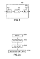
- An SRC system 100 may be represented as the association of an R-fold expander 101, followed by a low-pass filter 102, and followed by a P-fold decimator 103, as illustrated in Figure 1 .
- system 100 may be seen as a canonical representation for a resampler, 101 combined with 102 as an integer rate upsampler and 102 combined with 103 as an integer rate downsampler.
- This representation always exists and is unique. Therefore, it is a canonical representation.
- the canonical representation of an SRC may be different from the actual implementation.
- the canonical representation of the SRC system may be either unknown or difficult to retrieve.
- the parameters characterizing the SRC algorithms used in SRC systems may be defined by the properties of the low pass filter H(z) as it will be apparent to the person with ordinary skill in the art.
- the SRC system may be characterized, for example, by determining the z-transform of the impulse response H(z) of the low-pass filter, or its transfer
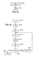
- an input discretized signal is received in a first step S201.
- a set of polyphase components is generated, based on the input signal.
- step S202 After step S202, a step S205 of feeding the SRC system with the polyphase components is performed.
- the polyphase components may be fed to a same instantiation of the SRC system.
- the SRC system may be instantiated a number of times equal to the number of polyphase components. Then, the processing of the polyphase components by the instantiations of the SRC system may be performed at the same time (in parallel).
- Other variants of the number of instantiations and feeding of polyphase components may also be applicable.
- a step S206 of generating an output signal is performed.
- the output signal is generated based on the output of the SRC system (or the outputs of the different instantiations of the SRC system).
- the output signal is generated by interleaving, shifting and adding the signals output by the SRC system (or the outputs of the different instantiations of the SRC system).
- the output signal may also be generated by an overlapping add operation on the outputs of the SRC system (for example in case of a real time application).
- step S213 it is verified whether all the output signals from the SRC system have been processed. If MP-1 output signal have been processed, then the generation of the output signal is terminated in step S214 and the output signal corresponds to the sum calculated in the last iteration of step S211. In the other case, the sum calculated in the last iteration of step S212 is time shifted in step S215 and the process goes back to step S210.
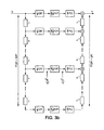
- Figure 3a shows a number PQR of parallel processing lines each comprising a QR-fold decimator, the SRC system with a rate of R/P and a PQ-fold expander.
- the input signal is fed to a first processing line and to a delay z -1 that outputs the delayed signal to another processing line and to another delay, and so on until the last processing line receives the input signal delayed PQR times.
- the first processing line outputs a signal to a delay z -1 that feds the delayed signal to an adder that sums the delayed signal and the output of the second processing line and so on.
- the combination of the delays and the adders performs the operation of overlap add.
- Figure 3b shows an alternative framework using anti-causal advances z.
- the input signal b is fed to the last processing line and the delays z -1 of the left side of the framework are replaced by advances z.
- FIG. 4 A system according to some embodiments is illustrated by Figure 4 .
- the system comprises an input port 401 for receiving a signal at a rate M times the operating input rate of the SRC system 402.
- the input port 401 may also receive a signal used for characterizing the SRC system 402.
- the system further comprises a processing unit 403 for generating the polyphase components. These polyphase components may be fed to the SRC system 403 through an output port 404 that may be coupled to an input port 405 of the SRC system.
- the system further comprises an input port 406 for receiving signals output by the SRC system through its output port 412 corresponding to the processed polyphase components. These processed polyphase components may be used by the processing unit 403 for generating and outputting the output signal through an output port 407.
- the output port 407 receives a signal at a rate q time the operating output rate of the SRC system.
- the feeding rate of 401 is identical to the filling rate of 407.
- the processing unit may comprise a decimator 408, an expander 409, and a time shifting unit 410.
- the system may comprise a characterization unit 411 for characterizing the SRC system.
- system may comprise a memory unit 413 for storing data for the implementation of a method according to embodiments of the invention, or storing a computer program according to embodiments of the invention.
- the upsampler may be characterized by its canonical representation through a low pass filter H(z).
- a sequence (S n ) n ⁇ N may be assimilated to its z-transform S(z).
- S 1 (z) obtained as the result of interleaving those 8 one-sample shifted vectors, i.e.: z - 1 ⁇ s k / 8 z k ⁇ [ 8.16 )
- S 2 (Z) is obtained as the result of interleaving those 8 two-sample shifted vectors, i.e. z - 2 ⁇ s k / 8 z k ⁇ [ 16 , 24 ) :
- the transfer function H e j ⁇ ⁇ R from the resampler of ratio R/P can be estimated and both in-band and out-of-band characterics can be recovered.
- Figures 7 and 8 illustrate an effect of the method that makes the SRC system shift invariant, which is the spectral unaliasing.
- Figure 7 shows the spectrum of an output signal of a conventional SRC system (the ordinate show the gain in dB, and the abscissa show the normalized pulsation). All the components of the spectrum are in the frequency band between 0 and 1.
- the spectrum comprises the main spectrum of the output signal A, and also aliased components B and C.
- Figure 8 shows the spectrum of an output signal of the same SRC system made shift-invariant according to an embodiment. In his spectrum, only the main spectrum A is in the frequency band between 0 and 1. The aliased components B and C have been rejected out of the band.
- the object of this appendix is to evaluate the polyphase expression of a resampled signal.
- S e j ⁇ ⁇ M includes M/R duplications of H e j ⁇ ⁇ R .
- Figures 5 and 6 illustrate how the transfer function of two different upsampler systems (plain and dotted curves) for rate x3 can be evaluated for respectively the in-band ( Figure 5 ) and the out-of-band ( Figure 6 ) domain.
- B (1) (Z)nd B (2) (z) The first set, b k M 1 z is obtained with a low-order low-pass filter.
- the second set of test vectors b k M 2 z is derived from b k M 1 z by a modulation at the Nyquist frequency (i.e. a multiplication by the sequence 1,-1,1,-1,1 ... ).
- the multirate framework from Figure 3 can be used in order to recover the impulse response h n instead.
- the impulse response h n is directly available as y n if an impulse is fed as Xn and Q is set to 1.
- the amount of processed vector needed is reduced: P processed vectors for the impulse method instead of at least PQR for other methods such as the transfer function method.
- P processed vectors for the impulse method instead of at least PQR for other methods such as the transfer function method.
- the redundancies aspects in the transfer function method guaranty a better robustness against quantization noises.
- the Total Harmonic Distortion (THD) method is a power comparison between the original signal (sine wave) and the signal obtained by extracting the harmonic partials (comb filter) generated by the system on the original sine wave.
- the Total Distortion (THD+Noise) method is a power comparison between the original signal (sine wave) and the signal obtained by removing the sine wave component from the distorted tone.
- the test input signal b is a sine wave which period in the oversampled domain is Mp samples.
- the width of the support of s is denoted lgt.
- the complex vector S k of size lgt is Discrete Fourier Transform of the output signal s.
- the Sine Sweep method consists in the generation of a sine sweep as the input signal and the examination in a time-frequency domain (e.g. a spectrogram) of the SRC processing.
- This examination reveals separable alias trajectories for each aliased components; it reveals also the characteristics from the in-band linear response which is roughly available as the time envelop from the time response.
- the Exponential Sine-Sweep consists in the generating an exponential sine-sweep in the oversampled domain and feeding it to the LSI system.
- the output reveals separately the linear characteristics, the stopband characteristics and the rounding-error characteristics.
- the Exponential Sine Sweep (ESS) method aims at characterizing simultaneously the linear and non-linear behaviour of a device (e.g. a transducer) provided that this device follows a model restricted to a certain subclass of Volterra Kernels.
- each distorted harmonic component appears as an anti-causal echo.
- Deconvolution separates each echo and allows objective measurement.
- the sine wave used in the Harmonic Distortion method is replaced by an Exponential Sine-Sweep.
- the Exponential Sine-Sweep (ESS) method is applied in the oversampled domain in order to characterize the shift-invariant system.
- the ESS method applied to the SRC system enables to access to the linear characteristics of the SRC (i.e. the in-band and out-of-band characteristics from the core low-pass filter H) as well as the harmonic distortion characteristics of the algorithms (originating from rounding errors in internal arithmetics).
- the Silence Sweep method allows the measure of the total distortion instead of the harmonic distortion.
- the idea relies on replacing the original sine sweep by a sine sweep subtracted from a pseudo-noise.
- Embodiments of the present invention can be embedded in a computer program product, which comprises all the features enabling the implementation of the methods described herein, and which - when loaded in an information processing system - is able to carry out these methods.
- Computer program means or computer program in the present context mean any expression, in any language, code or notation, of a set of instructions intended to cause a system having an information processing capability to perform a particular function either directly or after a conversion to another language.
- Such a computer program can be designed based on the flowchart of Figures 2a , 2b , 2c , Figure 3 , and the present description.
- the computer program can be stored on a computer or machine readable medium allowing data, instructions, messages or message packets, and other machine readable information to be read from the medium.
- the computer or machine readable medium may include non-volatile memory, such as ROM, Flash memory, Disk drive memory, CD-ROM, and other permanent storage. Additionally, a computer or machine readable medium may include, for example, volatile storage such as RAM, buffers, cache memory, and network circuits. Furthermore, the computer or machine readable medium may comprise computer or machine readable information in a transitory state medium such as a network link and/or a network interface, including a wired network or a wireless network, that allow a device to read such computer or machine readable information.
- a transitory state medium such as a network link and/or a network interface, including a wired network or a wireless network, that allow a device to read such computer or machine readable information.
- Embodiments of the invention can be embedded in hardware circuits.
- the circuits are implemented by the preparation of ASICs, FPGAs, microcontrollers or discrete logic elements by interconnecting an appropriate network of conventional component circuits.
- the circuit may also comprise memory elements such as ROMs, RAMs, EPROMs, EEPROMs, Flash memory, magnetic or optical cards, or any type of media suitable for storing electronic information.
Landscapes
- Engineering & Computer Science (AREA)
- Physics & Mathematics (AREA)
- Computer Hardware Design (AREA)
- Mathematical Physics (AREA)
- Quality & Reliability (AREA)
- Computer Networks & Wireless Communication (AREA)
- Signal Processing (AREA)
- Compression, Expansion, Code Conversion, And Decoders (AREA)
Abstract
There is described a method of making a linear periodically time varying system shift-invariant comprising the following steps implemented for each input signal the sample rate of which has to be converted:
- generating a set of polyphase components based on the input signal,
- feeding the generated set of polyphase components to the system, and
- generating an output signal by performing interleaving, shifting and addition on signals output by the system corresponding to the generated set of polyphase components processed by the system.
- generating a set of polyphase components based on the input signal,
- feeding the generated set of polyphase components to the system, and
- generating an output signal by performing interleaving, shifting and addition on signals output by the system corresponding to the generated set of polyphase components processed by the system.
Description
- The present invention generally relates to digital sample rate conversion systems, and more specifically to devices and methods for making such systems shift-invariant and/or characterizing such systems.
- Digital sample rate conversion (SRC) systems receive sampled input signals at a given sampling rate and output the signal with a different sampling rate. The SRC system may increase (upsample) or decrease (downsample) the sample rate of the signal.
- The sample rate conversion systems are widely used in audio or video systems for performing conversion of audio or video files from a given codec to another. SRC systems may have other applications.
- Before integrating a sample rate conversion system in a multimedia (e.g. audio and/or video) architecture, there may be the need of characterizing the SRC system for studying its behaviour.
- Different approaches to characterization and performance measurements for multirate systems exist in the prior art.
- SRC may be dealt with as a specific case of a multirate system (MRS). In some prior art approaches, fractional rate sampling rate convertors (SRC) are not considered as Linear Periodically Time Varying (LPTV) systems. For an SRC, input and output periods are constrained to be different. In other approaches, assuming an explicit definition of LPTV with potentially different input and output periods, SRC is clearly considered as LPTV. LPTV systems form a wider class than SRC since filter banks belong to LPTV.
- LPTV systems may be entirely described in a polyphase context with tools including: analysis network (PPAN), synthesis network (PPSN) and polyphase matrix.
- Typically, the following approach may be used in order to describe a LPTV system: Find a representation that embeds a Linear Time Invariant (LTI) system and characterize the LTI system with some suitable method.
- Various different approaches are possible. For example, the LTI system may include a MIMO LTI system characterized by a bi-spectrum. Other approaches include a linear switched time varying (LSTV) system.
- The characterizing bi-spectrum may be obtained through different means. For example via formal analysis by serial or parallel concatenation of basic building blocks (MIMO LTI system, decimator, expander, modulator), or via black box analysis with excitation of the system with a set of orthogonal test vectors.
- Several techniques may be used for characterizing sample rate conversion systems (SRC) from the outside (the SRC system being considered as a black box or a near black box (or grey) component).
- The parameters characterizing the SRC system may be:
- the in-band linear characteristics of the system,
- the out-of-band characteristics of the system that generates spectrum aliases, and
- the additional background noise due to rounding errors.
- The characterizing methods may be based on a distortion measurement either on a sine wave or on a sine sweep wave. The characterization methods may also be based on the reconstruction of the impulse response of the SRC system.
- However, SRC systems are not shift-invariant (or time-invariant) systems. For an SRC system, the output of a delayed sequence is not necessarily the delayed version of the resulting output of the non-delayed sequence. This lack of shift-invariance generates aliasing, which penalizes the characterization methods.
- Therefore, whereas the aliasing behaviour is not due to a non-linear behaviour, aliasing of SRC systems is usually studied as if it was a non-linear distortion with methods and criterion such as total distortion methods.
- In fact, for an SRC system, a source of non-linearity may be the rounding errors. Total distortion methods are thus unable to discriminate between aliasing and real non-linearity.
- Hence, there is a need for facilitating the characterization of the SRC systems.
- Therefore, a first aspect of the invention relates to a method for making SRC systems shift-invariant (or time-invariant).
- It is noted that embodiments of the invention may be equally applicable to any LPTV system (e.g. when P and R are not coprime), even though described below in the context to SRC systems only.
- According to the first aspect, there is provided a method of making a linear periodically time varying system (or an SRC system) shift-invariant (or time-invariant) as defined in
claim 1. - Once, the SRC system is made shift-invariant (or time-invariant) LTI (Linear Time Invariant) characterization methods can be applied and true non-linearity of the SRC system can be studied separately.
- A second aspect of the invention relates to methods for characterizing SRC systems.
- Embodiments of the invention are recited in the dependent claims attached hereto.
- For example, the method may be performed in real time. In such an embodiment, different instantiations of the SRC system may be used for generating in parallel the polyphase components.
- In other embodiments, the polyphase components may be generated by a same instantiation of the SRC system.
- The output signal may be generated by an overlapping-add operation.
- Once the method implemented, SRC systems behave as linear and shift invariant (LSI) systems. Hence, the SRC systems may be modelled as discrete filters operating in the oversampling domain.
- According to some embodiments, the alias components are pushed out of the bandwidth of the SRC system, which facilitates the characterization of the SRC system.
- Thus, methods for characterizing shift-invariant systems can be applied in the oversampled domain.
- For example, the impulse response characterization method or the transfer function characterization method may be used.
- Once the SRC system is made shift-invariant, any remaining distortion or background noise in the SRC system may be associated to internal rounding errors caused by the arithmetic of the SRC system.
- Therefore, any distortion method identifying these non-linearities can be used in the oversampled domain for characterizing those rounding errors, and then the SRC system.
- For example, the Harmonic distortion method, or the Exponential Sine-Sweep may be used.
- A third aspect of the present invention relates to a computer program product comprising one or more stored sequences of instructions that are accessible to a processor and which, when executed by the processor, cause the processor to carry out the steps of the method of the first and/or the second aspect of the present invention.
- A fourth aspect of the present invention relates to a system for implementing a method according to the first aspect.
- A fifth aspect of the present invention relates to a system for implementing a method according to the second aspect.
- The present invention is illustrated by way of example, and not by way of limitation, in the figures of the accompanying drawings, in which like reference numerals refer to similar elements and in which:
-
Figure 1 is a schematic illustration of an SRC system; -
Figures 2a ,2b, 2c are flowcharts illustrating steps of methods according to embodiments of the invention; -
Figures 3a and3b are a schematic illustrations of multirate frameworks according to embodiments of the invention; -
Figure 4 is a schematic illustration of a system according to embodiments of the invention; -
Figures 5 and 6 illustrate the evaluation of the transfer function of an SRC system according to embodiments of the invention; and -
Figures 7 and 8 illustrate the unaliasing effect of embodiments of the invention. - In the following, we consider a digital sampling rate conversion (SRC) system having a fractional ratio R/P (R and P being coprimes).
- An
SRC system 100 may be represented as the association of anR-fold expander 101, followed by a low-pass filter 102, and followed by aP-fold decimator 103, as illustrated inFigure 1 . - In some embodiments the
system 100 may be seen as a canonical representation for a resampler, 101 combined with 102 as an integer rate upsampler and 102 combined with 103 as an integer rate downsampler. - This representation always exists and is unique. Therefore, it is a canonical representation. The canonical representation of an SRC may be different from the actual implementation. In implementations that include multistage operations with possible interpolation algorithms, the canonical representation of the SRC system may be either unknown or difficult to retrieve.
- The parameters characterizing the SRC algorithms used in SRC systems may be defined by the properties of the low pass filter H(z) as it will be apparent to the person with ordinary skill in the art.
- Thus, the SRC system may be characterized, for example, by determining the z-transform of the impulse response H(z) of the low-pass filter, or its transfer
- function

- According to some embodiments, as illustrated by
Figure 2a , an input discretized signal, the sample rate of which is to be converted by the SRC system, is received in a first step S201. Then, during step S202, a set of polyphase components (as further described hereafter) is generated, based on the input signal. - For example, as illustrated by
Figure 2b , step S202 may comprise a step S203 of time shifting the input signal k times, with k being an integer inclusively comprised between 0 and MP-1 (M verifying M=RQ, q=PQ, and MP=qR, q and Q being integer numbers, R and P being coprime integers), and the step S204 of M-fold decimating the time shifted signals. - After step S202, a step S205 of feeding the SRC system with the polyphase components is performed.
- The polyphase components may be fed to a same instantiation of the SRC system. However, for example for real time applications, wherein the output samples of the different instantiations of the SRC systems produced at the same time are grouped within one frame, the SRC system may be instantiated a number of times equal to the number of polyphase components. Then, the processing of the polyphase components by the instantiations of the SRC system may be performed at the same time (in parallel). Other variants of the number of instantiations and feeding of polyphase components may also be applicable.
- Then, after step S205, a step S206 of generating an output signal is performed. The output signal is generated based on the output of the SRC system (or the outputs of the different instantiations of the SRC system). The output signal is generated by interleaving, shifting and adding the signals output by the SRC system (or the outputs of the different instantiations of the SRC system). The output signal may also be generated by an overlapping add operation on the outputs of the SRC system (for example in case of a real time application).
- For example, as illustrated by
Figure 2c , step S206 may comprise initializing the generation of the output signal S207, by receiving the signal output by the SRC corresponding to the polyphase component which has not been time shifted (corresponding to k=0). Then, in step S208, the received signal is expanded at a rate of PQ, and the expanded signal is then time shifted in step S209. Then, the process continues with step S210 by receiving the output signal of the SRC system that has been time shifted k+1 times. This output signal is expanded at a rate of PQ during step S211, and the resulting signal is added, in step S212, to a previous addition of the processed signals (corresponding to the polyphase components time shifted a number oftimes - The above described embodiment is also illustrated by the multirate frameworks of
Figures 3a and3b . -
Figure 3a shows a number PQR of parallel processing lines each comprising a QR-fold decimator, the SRC system with a rate of R/P and a PQ-fold expander. The input signal is fed to a first processing line and to a delay z-1 that outputs the delayed signal to another processing line and to another delay, and so on until the last processing line receives the input signal delayed PQR times. The first processing line outputs a signal to a delay z-1that feds the delayed signal to an adder that sums the delayed signal and the output of the second processing line and so on. The combination of the delays and the adders performs the operation of overlap add. -
Figure 3b shows an alternative framework using anti-causal advances z. In this framework, the input signal b is fed to the last processing line and the delays z-1 of the left side of the framework are replaced by advances z. - A system according to some embodiments is illustrated by
Figure 4 . - The system comprises an
input port 401 for receiving a signal at a rate M times the operating input rate of theSRC system 402. Theinput port 401 may also receive a signal used for characterizing theSRC system 402. - The system further comprises a
processing unit 403 for generating the polyphase components. These polyphase components may be fed to theSRC system 403 through anoutput port 404 that may be coupled to aninput port 405 of the SRC system. - The system further comprises an
input port 406 for receiving signals output by the SRC system through itsoutput port 412 corresponding to the processed polyphase components. These processed polyphase components may be used by theprocessing unit 403 for generating and outputting the output signal through anoutput port 407. - The
output port 407 receives a signal at a rate q time the operating output rate of the SRC system. The feeding rate of 401 is identical to the filling rate of 407. - The processing unit may comprise a
decimator 408, anexpander 409, and atime shifting unit 410. - According to some embodiments, the system may comprise a
characterization unit 411 for characterizing the SRC system. - Also, the system according to embodiments may comprise a
memory unit 413 for storing data for the implementation of a method according to embodiments of the invention, or storing a computer program according to embodiments of the invention. - In the following, the method for making the SRC system shift-invariant is further explicated,
- In the following, it is shown how a set of system responses organized as a sum of interleaved and shifted signal is linear and time-invariant when this set forms a set of regularly delayed signals from 0 to MP-1 samples.
- Under those conditions, the z-transforms S(z) of the interleave-shift-added (ISA) system responses follow an expression which allows a characterization of the SRC system for both in-band and out-of-band domains (B(z) being the z-transform from an interleaved test sequence):

- Let's consider the problem of characterizing an upsampler with a rate of R = 3. The upsampler may be characterized by its canonical representation through a low pass filter H(z). The R-polyphase decomposition (h1(zR))i∈[0,R) of H(z) is given as:

- For the sake of readability, in the following, a sequence (Sn)n∈Nmay be assimilated to its z-transform S(z).
- Now, we consider a set of test vectors

- The individual vectors


- For the matter of this example, consider M = 24, which is not too large but still shares a common denominator with most usual resampling ratios (apart ratios translating sampling rates from the 44.1 kHz domain to sampling rates simple multiple of 8kHz).
- Let's start with the processing (i.e. here, the upsampling) of each test vectors


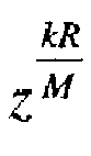

- In this case, we have M/R = Q = 8 and therefore the 8 first processed vectors form a polyphase decomposition of the unit impulse: S0/8(Z)S1/8(Z),..., S7/8(Z). Therefore, let's consider S0(z) obtained as the result of interleaving those 8 vectors:

- Now, S0(z) is separable; define β1(z) as the second term of this product:

- Then, we have:

- One may note that the 8 following processed vectors form another polyphase decomposition of the unit impulse: S8/8(z), S9/8(z), ... , S15/8(Z). We can consider S1(z) obtained as the result of interleaving those 8 one-sample shifted vectors, i.e.:


- Note also that the 8 last processed vectors form again another decomposition of the unit impulse: S16/8(Z), S17/8(z), ... , s23,$(z). S2(Z) is obtained as the result of interleaving those 8 two-sample shifted vectors, i.e.


- Finally we have S(z), the z-transform from the sequence obtained as the addition from the three previous sequences:

- We can recognize in

- Therefore, we have generated a sequence as the interleave-shift-add (ISA) operation from the processed test vectors


- We consider the case of a simple downsampler of
rate 1/P. - Test vectors


- Consider also the continuation of the test vectors


- The downsampling of any test vector


with ω ρ being a non-obvious root from Xp - 1.
Now, consider the z-transform S(z) of the sequence obtained by interleaving MP
consecutive sequences derived from

- Consider the second part from this expression:

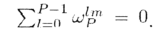
- Note that



- Now, let's return to the original evaluation:

- This concludes the evaluation of S(z) in the simple downsampling case:

- This equation is similar to Eq.(3). This proves once again that can be estimated and that both in-band and out-of-band characterics can be safely recovered.
- We consider the characterization of a resampler with a fractional ratio R/P, R and P being coprimes. Following the upsampler example, we assume that this resampler is characterized by the unknown filter H(z) in its canonical representation.
- An integer M is selected so that Q = M/R is an integer number. An integer q is defined as q = MP/R. The following relationships recap the properties between P, R, M and q:

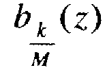
- Finally, we consider the set of test vectors

- Define also the composite root Ω m,n as:

- For further calculus, define also (cf. the upsampler example) and Bm(z) as:


k + IQ with k in∈[0,Q) and in∈[0, PR) covers the entire range [0, qR). Therefore, the previous sum can be rewritten as:
- For the second evaluation, we have


- Now, let evaluate


- The resampling of any test vector by the fractional ratio R/P results into the vector (cf. Appendix).

- Consider the ISA sequence, S(z), derived from qR consecutive sequences


Figure 3b .
- Let evaluate this expression in term of :

- Since P and R are coprimes, mR + nP mod (PQR) covers exactly the range [0, PQR) when m is in [0, P) and n in [0,RQ). Therefore, the double sum in m and n can be replaced by a simple sum in i, with m = ixR̅ , R̅ being the multiplicative inverse from R in the ring

- Since is a root of the unity, we have:

- This concludes the evaluation of S(z) and generalizes both Eq.(4) and Eq.(3):

- The transfer function

-
Figures 7 and 8 illustrate an effect of the method that makes the SRC system shift invariant, which is the spectral unaliasing.Figure 7 shows the spectrum of an output signal of a conventional SRC system (the ordinate show the gain in dB, and the abscissa show the normalized pulsation). All the components of the spectrum are in the frequency band between 0 and 1. The spectrum comprises the main spectrum of the output signal A, and also aliased components B and C.Figure 8 shows the spectrum of an output signal of the same SRC system made shift-invariant according to an embodiment. In his spectrum, only the main spectrum A is in the frequency band between 0 and 1. The aliased components B and C have been rejected out of the band. - The object of this appendix is to evaluate the polyphase expression of a resampled signal.
- Consider the input sequence which z-transform is b(z). Consider a fractional resampler xR/P the canonical representation of which is based on the low pass filter H(z). Let evaluate the z-transform s(z) of the resampled signal. In order to do so, consider first the z-transform σ(z) resulting from the R-expansion:

- The z-transform s(z) is obtained from σ(z) after a P-fold decimation; when we consider a 0 offset for this decimation, we obtain (with ωp being a root of Xp - 1 ):

- Altogether, we obtain:

- In the previous examples, the transfer function for a resampler with a fractional ratio R/P was established in Eq.(5), for instance, evaluated in the oversampled normalized domain:

- Note that


with, for instance the following weighting

- It is even possible to take into account spectrum duplicates corresponding to negative frequencies:

with, in that case, the weights updated accordingly:


- An additional possibility for recovering H(z) and to increase tolerance to zeros (and incidentally tolerance to floating-point rounding errors) is to consider multiple answers S (u)(z) to different sets of test vectors B(u)(z) instead of S(z) alone. In such case, the recovery formula Eq.(6) is generalized by:

with, once again, the generalized weighting

Said differently, it is enough for the aliased transfer functions

-
Figures 5 and 6 illustrate how the transfer function of two different upsampler systems (plain and dotted curves) for rate x3 can be evaluated for respectively the in-band (Figure 5 ) and the out-of-band (Figure 6 ) domain. One can see that in the in-band domain, the systems behave linearly. The spectral aliases have been pushed in the out-of-band. Those estimations were obtained with the help of complementary sets of test vectors, B(1)(Z)nd B(2)(z). The first set,


sequence 1,-1,1,-1,1 ... ). - Instead of recovering the transfer function

Figure 3 can be used in order to recover the impulse response hn instead. The impulse response hn is directly available as yn if an impulse is fed as Xn and Q is set to 1. When Xn is set to an impulse δ n, only remains

- In the impulse method, the amount of processed vector needed is reduced: P processed vectors for the impulse method instead of at least PQR for other methods such as the transfer function method. However, it is possible that the redundancies aspects in the transfer function method guaranty a better robustness against quantization noises.
- Those simple examples demonstrate the different possibilities available for estimating an upsampler transfer function and to reveal the upsampler design characteristics for both in-band and out-of-band spectral domains.
- The Total Harmonic Distortion (THD) method is a power comparison between the original signal (sine wave) and the signal obtained by extracting the harmonic partials (comb filter) generated by the system on the original sine wave.
- The Total Distortion (THD+Noise) method is a power comparison between the original signal (sine wave) and the signal obtained by removing the sine wave component from the distorted tone.
- The test input signal b is a sine wave which period in the oversampled domain is Mp samples.
- Then, the above discussed method making the SRC system shift-invariant is performed in order to produce the output signal s.
- The width of the support of s is denoted lgt.
- The complex vector S k of size lgt is Discrete Fourier Transform of the output signal s.
- The element indexed by

- Since the analysed system is made shift-invariant by the present method, the only source of harmonic non-linearities originates from rounding error due to the floating-point or fixed-point arithmetic used internally by the device.
- The Sine Sweep method consists in the generation of a sine sweep as the input signal and the examination in a time-frequency domain (e.g. a spectrogram) of the SRC processing. This examination reveals separable alias trajectories for each aliased components; it reveals also the characteristics from the in-band linear response which is roughly available as the time envelop from the time response.
- The Exponential Sine-Sweep consists in the generating an exponential sine-sweep in the oversampled domain and feeding it to the LSI system. The output reveals separately the linear characteristics, the stopband characteristics and the rounding-error characteristics.
- The Exponential Sine Sweep (ESS) method, aims at characterizing simultaneously the linear and non-linear behaviour of a device (e.g. a transducer) provided that this device follows a model restricted to a certain subclass of Volterra Kernels.
- When the ESS test vector is fed into a non-linear device, each distorted harmonic component appears as an anti-causal echo. Deconvolution separates each echo and allows objective measurement.
- The sine wave used in the Harmonic Distortion method is replaced by an Exponential Sine-Sweep. Then, the Exponential Sine-Sweep (ESS) method is applied in the oversampled domain in order to characterize the shift-invariant system.
- The ESS method applied to the SRC system enables to access to the linear characteristics of the SRC (i.e. the in-band and out-of-band characteristics from the core low-pass filter H) as well as the harmonic distortion characteristics of the algorithms (originating from rounding errors in internal arithmetics).
- The Silence Sweep method allows the measure of the total distortion instead of the harmonic distortion. The idea relies on replacing the original sine sweep by a sine sweep subtracted from a pseudo-noise.
- Embodiments of the present invention can be embedded in a computer program product, which comprises all the features enabling the implementation of the methods described herein, and which - when loaded in an information processing system - is able to carry out these methods. Computer program means or computer program in the present context mean any expression, in any language, code or notation, of a set of instructions intended to cause a system having an information processing capability to perform a particular function either directly or after a conversion to another language. Such a computer program can be designed based on the flowchart of
Figures 2a ,2b ,2c ,Figure 3 , and the present description. The computer program can be stored on a computer or machine readable medium allowing data, instructions, messages or message packets, and other machine readable information to be read from the medium. The computer or machine readable medium may include non-volatile memory, such as ROM, Flash memory, Disk drive memory, CD-ROM, and other permanent storage. Additionally, a computer or machine readable medium may include, for example, volatile storage such as RAM, buffers, cache memory, and network circuits. Furthermore, the computer or machine readable medium may comprise computer or machine readable information in a transitory state medium such as a network link and/or a network interface, including a wired network or a wireless network, that allow a device to read such computer or machine readable information. - Embodiments of the invention can be embedded in hardware circuits. For example, the circuits are implemented by the preparation of ASICs, FPGAs, microcontrollers or discrete logic elements by interconnecting an appropriate network of conventional component circuits. The circuit may also comprise memory elements such as ROMs, RAMs, EPROMs, EEPROMs, Flash memory, magnetic or optical cards, or any type of media suitable for storing electronic information.
- Expressions such as "comprise", "include", "incorporate", "contain", "is" and "have" are to be construed in a non-exclusive manner when interpreting the description and its associated claims, namely construed to allow for other items or components which are not explicitly defined also to be present. Reference to the singular is also to be construed in be a reference to the plural and vice versa.
- While there has been illustrated and described what are presently considered to be the preferred embodiments of the present invention, it will be understood by those skilled in the art that various other modifications may be made, and equivalents may be substituted, without departing from the true scope of the present invention. Additionally, many modifications may be made to adapt a particular situation to the teachings of the present invention without departing from the central inventive concept described herein. Furthermore, an embodiment of the present invention may not include all of the features described above. Therefore, it is intended that the present invention not be limited to the particular embodiments disclosed, but that the invention include all embodiments falling within the scope of the appended claims.
- A person skilled in the art will readily appreciate that various parameters disclosed in the description may be modified and that various embodiments disclosed may be combined without departing from the scope of the invention.
Claims (17)
- A method of making a linear periodically time varying system shift-invariant comprising the following steps implemented for each input signal the sample rate of which has to be converted:- generating (S202) a set of polyphase components based on the input signal,- feeding (S205) the generated set of polyphase components to the system, and- generating (S206) an output signal by performing interleaving, shifting and addition on signals output by the system corresponding to the generated set of polyphase components processed by the system.
- The method according to claim 1, wherein the linear periodically time varying system is a digital sample rate conversion system.
- The method according to claim 2, wherein each polyphase component of the set of polyphase components is fed to a respective instantiation of the sample rate conversion system.
- The method according to claim 2 or 3, wherein the sample rate conversion system has a fractional ratio
 - selecting three integer numbers Q, M and q that satisfy the following equations:M=RQ,q=PQ, andMP=qR,and wherein the generation of each polyphase component of the set of polyphase components comprises the following steps of:- time shifting (S203) the input signal a number of times comprised between 0 and MP, and- M-fold decimating (S204) the time shifted input signals.
 - The method according to claim 4, wherein the generation of the output signal comprises the following steps of:- q-fold expanding (S211 ) each signal output by the sample rate conversion system corresponding to the generated set of polyphase components processed by the sample rate conversion system,- adding each expanded output signal to a time shifted sum of previously expanded output signals (S212, S215).
- The method according to claim 4, wherein the generation of the output signal comprises the following steps of:- q-fold expanding (S211 ) each signal output by the sample rate conversion system corresponding to the generated set of polyphase components processed by the sample rate conversion system,- performing an overlapping add operation on the expanded output signals.
- A method of characterizing a linear periodically time varying system, comprising the following steps of:- implementing a method for making the linear periodically time varying system shift-invariant according to any one of claims 1 to 6, with at least one input signal being at least one of an impulse or a test sequence,- inputting the impulse and/or the test sequence, and- characterizing the linear periodically time varying system through the output signal.
- A method of characterizing a linear periodically time varying system comprising implementing a method for making the linear periodically time varying system shift-invariant according to any one of claims 1 to 6, with at least one input signal being at least one of a sine-sweep signal, a sine signal, multiple sine signals, a multi-sine signal, multiple multi-sine signals, a maximum length sequence, or an all pass filtered impulse signal.
- A method according to claim 8, wherein the characterization is performed by harmonic distortion or total harmonic distortion.
- A method according to any one of claims 8-9, wherein the characterization comprises a characterization of non-linearities of the linear periodically time varying system.
- A computer program product comprising a computer readable medium, having thereon a computer program comprising program instructions, the computer program being loadable into a data-processing unit and adapted to cause the data-processing unit to execute the steps of a method according to any one of claims 1 to 9 when the computer program is run by the data-processing unit.
- A system configured to make a linear periodically time varying system shift-invariant comprising:- a first input port (401) adapted to receive an input signal the sample rate of which is intended to be converted by the system,- a first output port (404) adapted to output polyphase components to the system,- a second input port (406) adapted to receive signals outputted by the system corresponding to the polyphase components processed by the system,- a processing unit (403) adapted to generate the polyphase components based on the input signal the sample rate of which is intended to be converted by the system, and for performing interleaving, shifting and addition the signals outputted by the system for generating an output signal, and- a second output port (407) adapted to output the generated output signal.
- The system according to claim 12, wherein the linear periodically time varying system is a digital sample rate conversion system.
- The system according to claim 13, wherein the processing unit is further configured to instantiate the sample rate conversion system for each polyphase component to be generated.
- The system according to claim 13 or 14, wherein the sample rate conversion system has a fractional ratio
 M=RQ,q=PQ, andMP=qR,and wherein the processing unit comprises:- a time shifting unit (410) adapted to time shift the input signal a number of times comprised between 0 and MP, and- an M-fold decimator (408) adapted to decimate the time shifted input signals.
 - The system according to claim 15, wherein the processing unit further comprises:- a q-fold expander (409) adapted to expand each signal output by the sample rate conversion system corresponding to the generated polyphase components processed by the sample rate conversion system, and- an adder and a time shifting unit adapted to add each expanded output signal to a time shifted sum of previously expanded output signals.
- A system configured to characterize a sample rate conversion system comprising:- a system according to any one of claims 13 to 16, and- a characterization unit adapted to perform a method according to any one of claims 7 to 10.
Priority Applications (3)
| Application Number | Priority Date | Filing Date | Title |
|---|---|---|---|
| EP10306182A EP2448118A1 (en) | 2010-10-27 | 2010-10-27 | Method of making a linear periodically time varying system shift-invariant |
| US13/881,581 US8823559B2 (en) | 2010-10-27 | 2011-10-27 | Shift-invariant digital sampling rate conversion system |
| PCT/EP2011/068882 WO2012055974A1 (en) | 2010-10-27 | 2011-10-27 | Shift- invariant digital sampling rate conversion system |
Applications Claiming Priority (1)
| Application Number | Priority Date | Filing Date | Title |
|---|---|---|---|
| EP10306182A EP2448118A1 (en) | 2010-10-27 | 2010-10-27 | Method of making a linear periodically time varying system shift-invariant |
Publications (1)
| Publication Number | Publication Date |
|---|---|
| EP2448118A1 true EP2448118A1 (en) | 2012-05-02 |
Family
ID=43825108
Family Applications (1)
| Application Number | Title | Priority Date | Filing Date |
|---|---|---|---|
| EP10306182A Withdrawn EP2448118A1 (en) | 2010-10-27 | 2010-10-27 | Method of making a linear periodically time varying system shift-invariant |
Country Status (3)
| Country | Link |
|---|---|
| US (1) | US8823559B2 (en) |
| EP (1) | EP2448118A1 (en) |
| WO (1) | WO2012055974A1 (en) |
Families Citing this family (1)
| Publication number | Priority date | Publication date | Assignee | Title |
|---|---|---|---|---|
| EP4033667A1 (en) * | 2021-01-22 | 2022-07-27 | Rohde & Schwarz GmbH & Co. KG | Phase-shifted sampling module and method for determining filter coefficients |
Family Cites Families (7)
| Publication number | Priority date | Publication date | Assignee | Title |
|---|---|---|---|---|
| US5537435A (en) * | 1994-04-08 | 1996-07-16 | Carney; Ronald | Transceiver apparatus employing wideband FFT channelizer with output sample timing adjustment and inverse FFT combiner for multichannel communication network |
| US6915225B2 (en) | 2003-05-15 | 2005-07-05 | Northrop Grumman Corporation | Method, apparatus and system for digital data resampling utilizing fourier series based interpolation |
| US7292166B2 (en) * | 2005-05-26 | 2007-11-06 | Advantest Corporation | Analog/digital converter and program therefor |
| US7583771B2 (en) * | 2006-08-22 | 2009-09-01 | Schweitzer Engineering Laboratories, Inc. | Systems and methods for resampling unreliable data |
| CN101601031A (en) | 2006-12-22 | 2009-12-09 | 迈克纳斯公司 | Use 2 nPoint FFT calculates non-2 nTreating apparatus, the method and system of point DFT |
| US20100100389A1 (en) | 2008-10-22 | 2010-04-22 | Vns Portfolio Llc | System for Signal Sample Rate Conversion |
| US8943112B2 (en) * | 2009-06-26 | 2015-01-27 | Syntropy Systems, Llc | Sampling/quantization converters |
-
2010
- 2010-10-27 EP EP10306182A patent/EP2448118A1/en not_active Withdrawn
-
2011
- 2011-10-27 US US13/881,581 patent/US8823559B2/en not_active Expired - Fee Related
- 2011-10-27 WO PCT/EP2011/068882 patent/WO2012055974A1/en not_active Ceased
Non-Patent Citations (4)
| Title |
|---|
| ARYAN SAADAT MEHR ET AL: "Representations of Linear Periodically Time-Varying and Multirate Systems", IEEE TRANSACTIONS ON SIGNAL PROCESSING, IEEE SERVICE CENTER, NEW YORK, NY, US, vol. 50, no. 9, 1 September 2002 (2002-09-01), XP011080235, ISSN: 1053-587X * |
| MEHR A S: "Alias-Component Matrices of Multirate Systems", IEEE TRANSACTIONS ON CIRCUITS AND SYSTEMS II: EXPRESS BRIEFS, IEEE, US, vol. 56, no. 6, 1 June 2009 (2009-06-01), pages 489 - 493, XP011257413, ISSN: 1549-7747 * |
| RAVINDRA DHULI ET AL: "Issues in the Implementation of General Dual-Rate Systems", INDIA CONFERENCE (INDICON), 2009 ANNUAL IEEE, IEEE, PISCATAWAY, NJ, USA, 18 December 2009 (2009-12-18), pages 1 - 4, XP031625420, ISBN: 978-1-4244-4858-6 * |
| TONGWEN CHEN ET AL: "Linear periodically time-varying discrete-time systems: aliasing and LTI approximations", DECISION AND CONTROL, 1996., PROCEEDINGS OF THE 35TH IEEE CONFERENCE O N KOBE, JAPAN 11-13 DEC. 1996, NEW YORK, NY, USA,IEEE, US, vol. 3, 11 December 1996 (1996-12-11), pages 2677 - 2682, XP010213620, ISBN: 978-0-7803-3590-5, DOI: 10.1109/CDC.1996.573508 * |
Also Published As
| Publication number | Publication date |
|---|---|
| US20130279562A1 (en) | 2013-10-24 |
| US8823559B2 (en) | 2014-09-02 |
| WO2012055974A1 (en) | 2012-05-03 |
Similar Documents
| Publication | Publication Date | Title |
|---|---|---|
| JP5638787B2 (en) | Subband signal processing | |
| JP5908472B2 (en) | Method for analyzing signals and providing instantaneous frequency and short-time Fourier transform, and device for analyzing signals | |
| US20040120361A1 (en) | Asynchronous sample rate converter and method | |
| US8825415B2 (en) | Methods and apparatuses for estimation and compensation on nonlinearity errors | |
| US7403875B2 (en) | System for reconstruction of non-uniformly sampled signals | |
| US20090128379A1 (en) | Method and apparatus for computing interpolation factors in sample rate conversion systems | |
| US7251271B1 (en) | Digital filter design | |
| Thyagarajan | Introduction to digital signal processing using MATLAB with application to digital communications | |
| CN109561437B (en) | Method and device for processing signal | |
| EP1684428A1 (en) | Sample rate converter | |
| US9608598B1 (en) | Cascaded integrator-comb filter as a non-integer sample rate converter | |
| Ortigueira et al. | Fractional discrete-time signal processing: scale conversion and linear prediction | |
| US8823559B2 (en) | Shift-invariant digital sampling rate conversion system | |
| US7023930B2 (en) | Reducing the crest factor of a multicarrier signal | |
| EP1569335B1 (en) | Method for implementing a fractional sample rate converter (f-src) and corresponding converter architecture | |
| EP1569336B1 (en) | Method for implementing a fractional sample rate converter (F-SRC) and corresponding converter architecture | |
| CN101879072B (en) | Extraction and filtering method and device for ultrasonic imaging | |
| US10943330B2 (en) | Image processing filter | |
| US10224062B1 (en) | Sample rate conversion with pitch-based interpolation filters | |
| JP2008021119A (en) | Digital filter and image processor using the same | |
| US6772022B1 (en) | Methods and apparatus for providing sample rate conversion between CD and DAT | |
| EP1295390B1 (en) | Universal sampling rate converter for digital audio frequencies | |
| Cho et al. | Design of a sample-rate converter from CD to DAT using fractional delay allpass filter | |
| Tang et al. | FPGA based I-FIR Non-uniform Filter Banks | |
| WO2002015406A1 (en) | Acquiring local signal behavior parameters |
Legal Events
| Date | Code | Title | Description |
|---|---|---|---|
| PUAI | Public reference made under article 153(3) epc to a published international application that has entered the european phase |
Free format text: ORIGINAL CODE: 0009012 |
|
| AK | Designated contracting states |
Kind code of ref document: A1 Designated state(s): AL AT BE BG CH CY CZ DE DK EE ES FI FR GB GR HR HU IE IS IT LI LT LU LV MC MK MT NL NO PL PT RO RS SE SI SK SM TR |
|
| AX | Request for extension of the european patent |
Extension state: BA ME |
|
| 17P | Request for examination filed |
Effective date: 20121031 |
|
| RAP1 | Party data changed (applicant data changed or rights of an application transferred) |
Owner name: OCT CIRCUIT TECHNOLOGIES INTERNATIONAL LIMITED |
|
| STAA | Information on the status of an ep patent application or granted ep patent |
Free format text: STATUS: THE APPLICATION HAS BEEN WITHDRAWN |
|
| 18W | Application withdrawn |
Effective date: 20170704 |