EP2447844A1 - Validating a correct operation of a HMI - Google Patents
Validating a correct operation of a HMI Download PDFInfo
- Publication number
- EP2447844A1 EP2447844A1 EP10090009A EP10090009A EP2447844A1 EP 2447844 A1 EP2447844 A1 EP 2447844A1 EP 10090009 A EP10090009 A EP 10090009A EP 10090009 A EP10090009 A EP 10090009A EP 2447844 A1 EP2447844 A1 EP 2447844A1
- Authority
- EP
- European Patent Office
- Prior art keywords
- hmi
- data
- indication data
- modified
- processor
- Prior art date
- Legal status (The legal status is an assumption and is not a legal conclusion. Google has not performed a legal analysis and makes no representation as to the accuracy of the status listed.)
- Granted
Links
Images



Classifications
-
- G—PHYSICS
- G06—COMPUTING OR CALCULATING; COUNTING
- G06F—ELECTRIC DIGITAL DATA PROCESSING
- G06F11/00—Error detection; Error correction; Monitoring
- G06F11/07—Responding to the occurrence of a fault, e.g. fault tolerance
- G06F11/16—Error detection or correction of the data by redundancy in hardware
- G06F11/1629—Error detection by comparing the output of redundant processing systems
- G06F11/1637—Error detection by comparing the output of redundant processing systems using additional compare functionality in one or some but not all of the redundant processing components
Definitions
- the invention relates to a method of validating a correct operation of a HMI, i.e. a human machine interface.
- the invention also relates to a HMI comprising a validation mode.
- the invention relates to a rail vehicle comprising the HMI.
- HMIs are often used to indicate safety related information.
- safety related information such as the velocity of the rail vehicle or the braking power of the braking system need to be displayed. If the displayed information is wrong or incomplete, or if the information is not displayed in a manner which can immediately be recognized by the driver, the safety of operation is not guaranteed.
- HMIs comprising digital screens for displaying visual information
- the invention particularly relates to this type of HMIs.
- Each matrix element of the screen can be controlled according to the corresponding pixel of an image to be displayed on the screen.
- a data processor of the HMI produces the image to be displayed.
- the image can directly be indicated by the display without further data processing. It is also possible that not all pixels of the image are calculated in each duty cycle of the data processor, but only these pixels which differ compared to a previous situation.
- the data processor may fail for different reasons.
- the result is a set of indication data (in particular an image to be displayed) which does not correspond to the information to be displayed as received by the HMI. Therefore, a second processor may be provided to check if the indication data produced by the first processor is equivalent to the information to be indicated by the HMI. If the check result is negative, i.e. there is a difference, a predetermined process is immediately triggered, for example the HMI is re-started or the screen is set blank.
- the HMI In order to prepare operation of such a HMI comprising two processors, the HMI should be validated for correct operation. It is possible to use a special purpose validation program performed by the first processor to create artefacts that shall be detected by the second processor (the safety processor in the following). Such a validation procedure can simulate hardware and/or software failures of the first processor (the main processor in the following) and can check their detection by the safety processor, but cannot detect failures of the standard program which is performed during normal operation by the main processor. It also cannot detect failures which only happen when this particular main processor performs the standard program. Furthermore, it cannot detect failures of the safety processor, including a corresponding program run by the safety processor, which only happen if the standard program is run by the main processor.
- the indication data which can directly be indicated by the indication device of the HMI and which are produced by the main processor (the first processor) for the purpose of validating the correct operation of the HMI and to use the safety processor (the second processor) to check if the modified indication data is equivalent to the information to be indicated by the HMI. It is decided that the validation was successful, if the check result means that the modified indication data is not equivalent to the information to be indicated. It is an important feature of the present invention that - during validation - the same predetermined procedure (the first predetermined procedure in the following) for producing the indication data is performed by the first processor as during normal operation of the HMI. This means that the handling of the input data which are input to the HMI is not altered until the indication data which can directly be indicated are obtained.
- the safety processor performs the same predetermined procedure (the second predetermined procedure in the following) for checking if the indication data is equivalent to the information to be indicated by the HMI.
- the indication data received and processed by the safety processor may be modified indication data or non-modified indication data. This means it can also be checked during validation, if the safety processor falsely detects differences between the indication data and the corresponding information to be indicated by the HMI.
- the check result of the safety processor that there is a difference can also mean that there is a failure of the main processor or of the first predetermined procedure.
- the first predetermined procedure or the second predetermined procedure may be a program, for example implemented in software and/or hardware.
- the validation mode according to the present invention only requires an additional program which controls the operation of the modification function and the operation of the decision making if the validation was successful or not.
- the method comprises the steps:
- the modified indication data can be output after step c) also to an indication device, e.g. for display on a screen.
- HMI HMI
- the output of the first processor and the output of the modification device may be the same output.
- the modification device may modify intermediate data which are processed to produce the indication data.
- step g) of the above-mentioned method and the description of the decision device means that it is decided that a validation of the HMI was not successful if the check result of step f) or of the second program means that the modified indication data is equivalent to the information to be indicated. In this case, the validation failed, because the modification was not detected by the safety processor.
- the validation procedure also checks the operation of the HMI while the modification function is switched off. Therefore, it is proposed to perform steps a), b), d), e) and f), wherein non-modified indication data obtained in step b) are output in step d) and input to the second processor in step e) and the non-modified indication data are checked in step f) instead of the modified indication data, and by deciding that the validation was successful if the check result of step f) means that the indication data is equivalent to the information to be indicated.
- the HMI comprises a second validation mode in which a further validation procedure is performed by performing the second program using the second processor in a manner in which the non-modified indication data produced by the first program are checked - instead of the modified indication data - for being equivalent to the information to be indicated by the HMI and in which the decision device decides that the validation was successful if the check result of step f) means that the indication data is equivalent to the information to be indicated.
- steps a) to g) are repeated wherein the indication data are modified in step c) in a different manner.
- the modification device of the HMI may be adapted to modify the indication data in a different manner during repeated validation of the HMI. Different modifications increase the reliability of the validation.
- the first predetermined procedure and the second predetermined procedure are exactly the same predetermined procedures as being performed during normal operation of the HMI, when the indication data are not modified.
- the invention can also comprise the normal operation of the HMI.
- the method starts with the validation and then, after successful validation, the normal operation of the HMI is performed using the first predetermined procedure and the second predetermined procedure.
- the normal operation is performed in the manner defined by claim 2, with the exception that the result is not a validation result but a result of the normal operation of the safety processor: it is decided that operation is failure-free if the check result of step f) means that the indication data is equivalent to the information to be indicated.
- the safety processor may perform the check if the modified indication data (or the non-modified indication data) are equivalent to the information to be indicated by the HMI for example in the following manner: It may calculate a characteristic value from the indication data or from a part of the indication data, wherein the part may correspond to a pre-determined display region where the information is to be displayed.
- the pre-determined region may be a part of the display area where the velocity of a rail vehicle is to be displayed.
- the HMI may be part of the control desk of the rail vehicle.
- the characteristic value is compared with an expected value which corresponds to the information to be displayed by the HMI.
- the characteristic value may be a so-called CRC value (cyclic redundancy check value).
- CRC value cyclic redundancy check value
- the indication data can be stored in a display memory, i.e. a data storage of the display.
- the display memory is a buffer which is automatically read out repeatedly in regular cycles to produce and refresh the image on a screen.
- the indication data may also be data to be processed according to a third predetermined procedure to obtain the data which can be stored in the display memory.
- the first predetermined procedure is adapted to calculate from a plurality of information the information to be displayed.
- the plurality of information may comprise different measurement values of the same quantity, in particular physical quantity, like speed, rotational speed, distance, electric voltage, electric current.
- the third predetermined procedure may just produce the corresponding presentation for indication (in particular for display).
- Fig. 1 shows an example of an arrangement in a rail vehicle.
- a signal source 1 is connected to a first computer 3 via a data transfer line 2.
- the signal source 1 is, for example, a speed sensor or a device for calculating a speed value from the measurement value of a speed sensor.
- the first computer 3 is connected to a data bus 4, for example a multi-functional vehicle bus (MVB) of the rail vehicle.
- a second computer 5 is connected to the data bus 4. The first computer transfers the measurement values continuously to the second computer via the data bus 4.
- MVB multi-functional vehicle bus
- the second computer 5 is connected to the display device 9 via a further data transfer line 7, which may be an Ethernet data bus.
- a switch 8 may be part of the data transfer line 7, for routing the data to be transferred.
- the speed values which are received by the second computer 5 are transferred to the display device 9 via the data transfer line 7.
- the rectangular frame 91 denotes the outline of the display device 9.
- this display area 22 may be a LCD display, a OLED (organic light emitting diode) display or a TFT display.
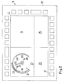
- the display area 22 is divided into four regions 23, 24, 25 and 26. In the region 23, the speed of the vehicle is displayed.
- Region 24 may display monitoring information for monitoring the state of technical devices of the vehicle, region 25 may display supplementary driving information to the driver and region 26 may display responses of the vehicle control system to input made by the driver.
- rectangular blocks are shown, one of which is denoted by reference numeral 21. These areas may be touched by the driver and corresponding input signals or input data is produced.
- the ten quadratic areas under the display area 22 may correspond to the numerals 0 to 9.
- Other touch sensitive areas may correspond to specific functions, such as increase or decrease illumination intensity of the display or display background.
- the speed in km/h is indicated as a number (here "133") within a circular line in the centre 34 of display region 23.
- a pointer 31 or “needle” is displayed which points to the value "133" on the circular scale having the range from “0" to "400”.
- a circular line or bar is extending from "0" of the scale to "150” of the scale. The colour of the bar changes at the value "80" of the scale.
- the bar segment from “0” to "80” is denoted by 32 and the bar segment from "80" to "150” is denoted by 33.
- the region from "80" to "150” indicates to the driver that the speed should be in this speed region, i.e. should be not smaller than 80 km/h and should be not greater than 150 km/h.
- Fig. 3 shows a HMI 71.
- functions are mentioned. These functions may be realised by computer software and/or hardware, for example.
- communication devices are mentioned. At least some of the functions of the communication devices may also be realised by computer software and/or hardware.
- Input data to the HMI 71 are transferred via transfer line 68, which is adapted for safe communication, to a corresponding communication device 72 of HMI 71.
- the communication device 72 may receive different measurement values of the same quantity (e.g. the velocity, i.e. speed of a rail vehicle) from different sources, not shown in Fig. 3 .
- the digital speed value "133" in the centre 34 of display region 23 in Fig. 2 may stem from a different speed sensor than the speed value indicated by the needle 31.
- Some of the measured speed values may differ from others, although the vehicle is actually driving at only one speed.
- One reason for this is the tolerance of measurement, another reason is that some wheels are subject to traction and braking and - therefore - the rotation of the wheel does not correspond to the actual speed of the vehicle.
- a third reason may be a failure of a speed sensor.
- the communication device 72 of HMI 71 is part of a main processor 69.
- the plurality of speed signals which is received by the communication device 72 is transferred to a data processing function 73 (which corresponds to a first predetermined process) which processes the speed signals in order to produce one or more than one speed values to be displayed.
- This one speed value or these more than one speed values may be the indication data to be displayed.
- data processing function 73 may also produce the image data to be displayed, which correspond to the speed value(s).
- the image data are the indication data.
- the production of the image data is performed according to the third predetermined procedure, which means that the same speed value(s) to be displayed results in the same image data, as long as the third predetermined procedure is always performed in the same manner. Since the third predetermined procedure is usually part of the HMI and has been performed many times for different types of applications, it can be expected that the procedure is performed free of failure. However, this does not apply to the calculation of the speed value(s) to be displayed (first predetermined procedure). This is a function which is designed for a specific application and requires validation. Nevertheless the invention allows encompassing failures of both the first and third predetermined procedure.
- Visualization function 74 receives the output of data processing function 73. Visualization function 74 is controlling the display according to the output of data processing function 73 to produce a picture which corresponds to the indication data produced by data processing function 73. If data processing function 73 outputs speed value(s) to be indicated, the third predetermined procedure is performed by visualization function 74.
- the example described before relates to the display of speed values.
- the corresponding problem and solution may apply to other applications, such as the display of temperature values or of the braking power of the braking system of a rail vehicle.
- HMI 71 also comprises a safety processor 70 which also receives the input data which is received by communication device 72 and is output to data processing function 73.
- the receiving device (preferably adapted to perform failure-safe receiving of data) of safety processor 70 is denoted by 78. Therefore, safety processor 70 receives the information to be displayed and can use this information in order to check the correct operation of the display of HMI 71.
- Blocks 79 and 80 represent functions which contribute to the safe signal transfer to safety processor 70.
- Function 75 of safety processor 70 receives an output signal of display control function 74 in order to obtain information of the actual display content and/or to obtain data corresponding to the actually displayed picture. Therefore, the operation of the complete main processor (including the data processing function 73) can be checked by safety processor 70.
- the checking function 76 of safety processor 70 performs the check according to a second predetermined procedure.
- the result of the check is output to evaluation device 77 which triggers a predetermined fall-back procedure (such as switching off the screen or re-starting the HMI) if the check results indicate that the information to be displayed does not correspond to the actual display content. Therefore, the function of the evaluation device also includes making the decision that a validation of the HMI 71 was successful if a check result of the checking function 76 means that the modified indication data is not equivalent to the information to be indicated.
- Fig 4 is similar to Fig. 3 .
- the same numerals in Fig. 3 and 4 denote the same functional blocks and devices.
- Main processor 69 comprises compared to Fig. 3 an additional function, namely the modification function 84.
- the input data which are received by the communication device 72 are output to the modification function 84.
- the modification function may receive the output of data processing function as input signal.
- modification function 84 modifies the output of data processing function 73. If the third predetermined procedure is performed by the visualization function 74, modification function 84 may receive the output signal of visualization function 74 and may modify this output signal directly.
- the output signal of visualization function 74 is modified compared to the case in which the modification function 84 is disabled. Therefore, the output signal of visualization function 74 which is output to function 75 of safety processor 70 should not correspond to the information to be displayed.
- the checking function 76 should detect this difference and should output a corresponding check result to evaluation device 77. Therefore, if checking function 76 does not output the check result that there is a difference, evaluation device 77 decides that the validation has failed.
- the output of display control function 74 may directly be output to the display (not shown in Fig. 3 and 4 ) of the HMI 71.
Landscapes
- Engineering & Computer Science (AREA)
- Theoretical Computer Science (AREA)
- Quality & Reliability (AREA)
- Physics & Mathematics (AREA)
- General Engineering & Computer Science (AREA)
- General Physics & Mathematics (AREA)
- User Interface Of Digital Computer (AREA)
Abstract
a) receiving input data comprising information to be indicated by the HMI (71) and supplying the input data to a first processor (69) of the HMI, and
b) processing (73) the input data using the first processor (69) according to a first predetermined procedure for producing indication data which unambiguously define the way an indication device of the HMI (71) has to indicate the information,
c) modifying (84) the indication data for the purpose of validating the correct operation of the HMI (71) and obtaining modified indication data,
d) outputting the modified indication data to a second processor (70),
e) inputting the modified indication data and the input data to the second processor (70)
f) processing (76) the modified indication data according to a second predetermined procedure for checking if the modified indication data are equivalent to the information to be indicated by the HMI (71) and outputting a corresponding check result,
g) deciding (77) that the validation was successful if the check result of step f) means that the modified indication data is not equivalent to the information to be indicated,
wherein the first predetermined procedure and the second predetermined procedure are exactly the same predetermined procedures as being performed during normal operation of the HMI (71), when the indication data are not modified.
Description
- The invention relates to a method of validating a correct operation of a HMI, i.e. a human machine interface. The invention also relates to a HMI comprising a validation mode. In addition, the invention relates to a rail vehicle comprising the HMI.
- HMIs are often used to indicate safety related information. In particular during the operation of rail vehicles safety related information such as the velocity of the rail vehicle or the braking power of the braking system need to be displayed. If the displayed information is wrong or incomplete, or if the information is not displayed in a manner which can immediately be recognized by the driver, the safety of operation is not guaranteed.
- In recent years, HMIs have been developed comprising digital screens for displaying visual information, and the invention particularly relates to this type of HMIs. Each matrix element of the screen can be controlled according to the corresponding pixel of an image to be displayed on the screen. A data processor of the HMI produces the image to be displayed. The image can directly be indicated by the display without further data processing. It is also possible that not all pixels of the image are calculated in each duty cycle of the data processor, but only these pixels which differ compared to a previous situation.
- The data processor may fail for different reasons. The result is a set of indication data (in particular an image to be displayed) which does not correspond to the information to be displayed as received by the HMI. Therefore, a second processor may be provided to check if the indication data produced by the first processor is equivalent to the information to be indicated by the HMI. If the check result is negative, i.e. there is a difference, a predetermined process is immediately triggered, for example the HMI is re-started or the screen is set blank.
- In order to prepare operation of such a HMI comprising two processors, the HMI should be validated for correct operation. It is possible to use a special purpose validation program performed by the first processor to create artefacts that shall be detected by the second processor (the safety processor in the following). Such a validation procedure can simulate hardware and/or software failures of the first processor (the main processor in the following) and can check their detection by the safety processor, but cannot detect failures of the standard program which is performed during normal operation by the main processor. It also cannot detect failures which only happen when this particular main processor performs the standard program. Furthermore, it cannot detect failures of the safety processor, including a corresponding program run by the safety processor, which only happen if the standard program is run by the main processor.
- It is an object of the present invention to provide a method of validating a correct operation of a HMI, a HMI comprising a validation mode and a rail vehicle comprising the HMI, wherein the reliability of the validation is improved and the effort for performing the validation is reduced.
- It is proposed to modify the indication data, which can directly be indicated by the indication device of the HMI and which are produced by the main processor (the first processor) for the purpose of validating the correct operation of the HMI and to use the safety processor (the second processor) to check if the modified indication data is equivalent to the information to be indicated by the HMI. It is decided that the validation was successful, if the check result means that the modified indication data is not equivalent to the information to be indicated. It is an important feature of the present invention that - during validation - the same predetermined procedure (the first predetermined procedure in the following) for producing the indication data is performed by the first processor as during normal operation of the HMI. This means that the handling of the input data which are input to the HMI is not altered until the indication data which can directly be indicated are obtained. This means, for example, that the same program can be used for operating the first processor. There is therefore an additional modification function which acts on the indication data produced by the first processor. For normal operation, this additional modification function is disabled. Enabling and disabling the modification function can be performed by a signal received as input together with the input data or by configuration settings etc.
- The same applies to the predetermined procedure which is performed by the safety processor (the second processor). During validation and during normal operation, the safety processor performs the same predetermined procedure (the second predetermined procedure in the following) for checking if the indication data is equivalent to the information to be indicated by the HMI. During validation mode, the indication data received and processed by the safety processor may be modified indication data or non-modified indication data. This means it can also be checked during validation, if the safety processor falsely detects differences between the indication data and the corresponding information to be indicated by the HMI. Of course, the check result of the safety processor that there is a difference can also mean that there is a failure of the main processor or of the first predetermined procedure.
- The first predetermined procedure or the second predetermined procedure may be a program, for example implemented in software and/or hardware. For example, the validation mode according to the present invention only requires an additional program which controls the operation of the modification function and the operation of the decision making if the validation was successful or not.
- In particular, a method of validating a correct operation of a HMI is proposed. The method comprises the steps:
- a) receiving input data comprising information to be indicated by the HMI and supplying the input data to a first processor of the HMI, and
- b) processing the input data using the first processor according to a first predetermined procedure for producing indication data which unambiguously define the way an indication device of the HMI will indicate the information,
- c) modifying the indication data for the purpose of validating the correct operation of the HMI and obtaining modified indication data,
- d) outputting the modified indication data to a second processor,
- e) inputting the modified indication data and the input data to the second processor
- f) processing the modified indication data according to a second predetermined procedure for checking if the modified indication data is equivalent to the information to be indicated by the HMI (according to the received input data) and outputting a corresponding check result,
- g) deciding that the validation was successful if the check result of step f) means that the modified indication data is not equivalent to the information to be indicated,
- In particular, the modified indication data can be output after step c) also to an indication device, e.g. for display on a screen.
- In addition, a HMI is proposed, comprising the following:
- a data input for receiving input data comprising information to be indicated by the HMI,
- an indication device adapted to indicate the information to a human,
- a first processor which is connected to the data input for receiving the input data,
- a first program implementing a first predetermined procedure for producing indication data which unambiguously define the way an indication device of the HMI will indicate the information, wherein the first processor is adapted to perform the first program,
- a modification device adapted to modify the indication data for the purpose of validating the correct operation of the HMI and obtaining modified indication data,
- a second processor, which is also connected to the data input for receiving the input data and which is connected to an output of the first processor and to an output of the modification device for receiving the modified indication data,
- a second program implementing a second predetermined procedure for checking if the modified indication data is equivalent to the information to be indicated by the HMI according to the input data received at the data input and for outputting a corresponding check result, wherein the second processor is adapted to perform the second program,
- In particular, there is a decision device adapted to decide that a validation of the HMI was successful if a check result of the second program means that the modified indication data is not equivalent to the information to be indicated, However, the decision can alternatively be made by an operator.
- The output of the first processor and the output of the modification device may be the same output. For example, the modification device may modify intermediate data which are processed to produce the indication data.
- Of course, step g) of the above-mentioned method and the description of the decision device means that it is decided that a validation of the HMI was not successful if the check result of step f) or of the second program means that the modified indication data is equivalent to the information to be indicated. In this case, the validation failed, because the modification was not detected by the safety processor.
- However, it is preferred that the validation procedure also checks the operation of the HMI while the modification function is switched off. Therefore, it is proposed to perform steps a), b), d), e) and f), wherein non-modified indication data obtained in step b) are output in step d) and input to the second processor in step e) and the non-modified indication data are checked in step f) instead of the modified indication data, and by deciding that the validation was successful if the check result of step f) means that the indication data is equivalent to the information to be indicated. This corresponds to an embodiment of the HMI, wherein the HMI comprises a second validation mode in which a further validation procedure is performed by performing the second program using the second processor in a manner in which the non-modified indication data produced by the first program are checked - instead of the modified indication data - for being equivalent to the information to be indicated by the HMI and in which the decision device decides that the validation was successful if the check result of step f) means that the indication data is equivalent to the information to be indicated.
- This further validation procedure will detect any failure of the normal operation.
- Preferably, steps a) to g) are repeated wherein the indication data are modified in step c) in a different manner. Correspondingly, the modification device of the HMI may be adapted to modify the indication data in a different manner during repeated validation of the HMI. Different modifications increase the reliability of the validation.
- The main processor produces (by processing the input data according to the first predetermined procedure) the indication data. These indication data unambiguously define the way an indication device of the HMI has to indicate the information contained in the indication data. This means that the indication data can either directly be indicated by the indication device without further data processing (e.g. the indication data are a two-dimensional image to be displayed or a part, such as an rectangular area, of the image to be displayed) or there is a third predetermined procedure which defines how the indication data are to be processed to result in data which can directly be indicated by the indication device without further data processing (e.g. the indication data define the angle and/or position of a graphical element, such as an arrow, which corresponds to a measurement value to be indicated, for example a velocity of a rail vehicle).
- As mentioned above, the first predetermined procedure and the second predetermined procedure are exactly the same predetermined procedures as being performed during normal operation of the HMI, when the indication data are not modified. This means the invention can also comprise the normal operation of the HMI. For example, the method starts with the validation and then, after successful validation, the normal operation of the HMI is performed using the first predetermined procedure and the second predetermined procedure. In particular, the normal operation is performed in the manner defined by
claim 2, with the exception that the result is not a validation result but a result of the normal operation of the safety processor: it is decided that operation is failure-free if the check result of step f) means that the indication data is equivalent to the information to be indicated. - In case of a display device, the safety processor may perform the check if the modified indication data (or the non-modified indication data) are equivalent to the information to be indicated by the HMI for example in the following manner: It may calculate a characteristic value from the indication data or from a part of the indication data, wherein the part may correspond to a pre-determined display region where the information is to be displayed. For example, the pre-determined region may be a part of the display area where the velocity of a rail vehicle is to be displayed. In particular, the HMI may be part of the control desk of the rail vehicle. Then, the characteristic value is compared with an expected value which corresponds to the information to be displayed by the HMI. The characteristic value may be a so-called CRC value (cyclic redundancy check value). However, the only requirement for the characteristic value is that it can unambiguously be calculated and that the result of the calculation is reproducible. The resulting unique value represents the information which is displayed.
- For example, the indication data can be stored in a display memory, i.e. a data storage of the display. Often, the display memory is a buffer which is automatically read out repeatedly in regular cycles to produce and refresh the image on a screen. However, as mentioned above, the indication data may also be data to be processed according to a third predetermined procedure to obtain the data which can be stored in the display memory.
- Preferably, the first predetermined procedure is adapted to calculate from a plurality of information the information to be displayed. In particular, the plurality of information may comprise different measurement values of the same quantity, in particular physical quantity, like speed, rotational speed, distance, electric voltage, electric current. In contrast, the third predetermined procedure may just produce the corresponding presentation for indication (in particular for display).
- Specific examples of the present invention will be described with reference to the attached figures:
- Fig. 1
- an example of a control and display system in the control desk of a rail vehicle,
- Fig. 2
- parts of an HMI comprising display areas and input means which are visible to the driver,
- Fig. 3
- a schematic diagram showing functional blocks of a HMI comprising a main processor and a safety processor, wherein the modification function is not shown, i.e. the diagram corresponds to the normal operation of the HMI,
- Fig. 4
- a schematic diagram of the HMI shown in
Fig. 3 comprising the additional modification function. -
Fig. 1 shows an example of an arrangement in a rail vehicle. Asignal source 1 is connected to afirst computer 3 via adata transfer line 2. Thesignal source 1 is, for example, a speed sensor or a device for calculating a speed value from the measurement value of a speed sensor. Thefirst computer 3 is connected to adata bus 4, for example a multi-functional vehicle bus (MVB) of the rail vehicle. A second computer 5 is connected to thedata bus 4. The first computer transfers the measurement values continuously to the second computer via thedata bus 4. - The second computer 5 is connected to the
display device 9 via a furtherdata transfer line 7, which may be an Ethernet data bus. Aswitch 8 may be part of thedata transfer line 7, for routing the data to be transferred. The speed values which are received by the second computer 5 are transferred to thedisplay device 9 via thedata transfer line 7. - In
Fig. 2 , therectangular frame 91 denotes the outline of thedisplay device 9. Within the innerrectangular frame 22, information can be displayed to the vehicle driver. For example, thisdisplay area 22 may be a LCD display, a OLED (organic light emitting diode) display or a TFT display. Thedisplay area 22 is divided into fourregions region 23, the speed of the vehicle is displayed. Region 24 may display monitoring information for monitoring the state of technical devices of the vehicle,region 25 may display supplementary driving information to the driver andregion 26 may display responses of the vehicle control system to input made by the driver. - Within the
outline 91 of thedisplay device 9, but outside of thedisplay area 22, rectangular blocks are shown, one of which is denoted by reference numeral 21. These areas may be touched by the driver and corresponding input signals or input data is produced. For example, the ten quadratic areas under thedisplay area 22 may correspond to the numerals 0 to 9. Other touch sensitive areas may correspond to specific functions, such as increase or decrease illumination intensity of the display or display background. - Within
pre-determined region 23, three different types of speed related information are displayed. First, the speed in km/h is indicated as a number (here "133") within a circular line in thecentre 34 ofdisplay region 23. Second, a pointer 31 or "needle" is displayed which points to the value "133" on the circular scale having the range from "0" to "400". Third, a circular line or bar is extending from "0" of the scale to "150" of the scale. The colour of the bar changes at the value "80" of the scale. The bar segment from "0" to "80" is denoted by 32 and the bar segment from "80" to "150" is denoted by 33. The region from "80" to "150" indicates to the driver that the speed should be in this speed region, i.e. should be not smaller than 80 km/h and should be not greater than 150 km/h. -
Fig. 3 shows aHMI 71. In the following, several "functions" are mentioned. These functions may be realised by computer software and/or hardware, for example. Also "communication devices" are mentioned. At least some of the functions of the communication devices may also be realised by computer software and/or hardware. - Input data to the
HMI 71 are transferred viatransfer line 68, which is adapted for safe communication, to acorresponding communication device 72 ofHMI 71. Thecommunication device 72 may receive different measurement values of the same quantity (e.g. the velocity, i.e. speed of a rail vehicle) from different sources, not shown inFig. 3 . For example, the digital speed value "133" in thecentre 34 ofdisplay region 23 inFig. 2 may stem from a different speed sensor than the speed value indicated by the needle 31. In practice, there are often more speed sensors than values to be displayed. Some of the measured speed values may differ from others, although the vehicle is actually driving at only one speed. One reason for this is the tolerance of measurement, another reason is that some wheels are subject to traction and braking and - therefore - the rotation of the wheel does not correspond to the actual speed of the vehicle. A third reason may be a failure of a speed sensor. - The
communication device 72 ofHMI 71 is part of amain processor 69. The plurality of speed signals which is received by thecommunication device 72 is transferred to a data processing function 73 (which corresponds to a first predetermined process) which processes the speed signals in order to produce one or more than one speed values to be displayed. This one speed value or these more than one speed values may be the indication data to be displayed. - Alternatively,
data processing function 73 may also produce the image data to be displayed, which correspond to the speed value(s). In this case, the image data are the indication data. The production of the image data is performed according to the third predetermined procedure, which means that the same speed value(s) to be displayed results in the same image data, as long as the third predetermined procedure is always performed in the same manner. Since the third predetermined procedure is usually part of the HMI and has been performed many times for different types of applications, it can be expected that the procedure is performed free of failure. However, this does not apply to the calculation of the speed value(s) to be displayed (first predetermined procedure). This is a function which is designed for a specific application and requires validation. Nevertheless the invention allows encompassing failures of both the first and third predetermined procedure. -
Visualization function 74 receives the output ofdata processing function 73.Visualization function 74 is controlling the display according to the output ofdata processing function 73 to produce a picture which corresponds to the indication data produced bydata processing function 73. Ifdata processing function 73 outputs speed value(s) to be indicated, the third predetermined procedure is performed byvisualization function 74. - The example described before relates to the display of speed values. However, the corresponding problem and solution may apply to other applications, such as the display of temperature values or of the braking power of the braking system of a rail vehicle.
-
HMI 71 also comprises asafety processor 70 which also receives the input data which is received bycommunication device 72 and is output todata processing function 73. The receiving device (preferably adapted to perform failure-safe receiving of data) ofsafety processor 70 is denoted by 78. Therefore,safety processor 70 receives the information to be displayed and can use this information in order to check the correct operation of the display ofHMI 71.Blocks safety processor 70. -
Function 75 ofsafety processor 70 receives an output signal ofdisplay control function 74 in order to obtain information of the actual display content and/or to obtain data corresponding to the actually displayed picture. Therefore, the operation of the complete main processor (including the data processing function 73) can be checked bysafety processor 70. The checkingfunction 76 ofsafety processor 70 performs the check according to a second predetermined procedure. The result of the check is output toevaluation device 77 which triggers a predetermined fall-back procedure (such as switching off the screen or re-starting the HMI) if the check results indicate that the information to be displayed does not correspond to the actual display content. Therefore, the function of the evaluation device also includes making the decision that a validation of theHMI 71 was successful if a check result of the checkingfunction 76 means that the modified indication data is not equivalent to the information to be indicated. -
Fig 4 is similar toFig. 3 . The same numerals inFig. 3 and4 denote the same functional blocks and devices. -
Main processor 69 comprises compared toFig. 3 an additional function, namely themodification function 84. The input data which are received by thecommunication device 72 are output to themodification function 84. Alternatively or in addition, the modification function may receive the output of data processing function as input signal. In any case,modification function 84 modifies the output ofdata processing function 73. If the third predetermined procedure is performed by thevisualization function 74,modification function 84 may receive the output signal ofvisualization function 74 and may modify this output signal directly. - In any case, the output signal of
visualization function 74 is modified compared to the case in which themodification function 84 is disabled. Therefore, the output signal ofvisualization function 74 which is output to function 75 ofsafety processor 70 should not correspond to the information to be displayed. The checkingfunction 76 should detect this difference and should output a corresponding check result toevaluation device 77. Therefore, if checkingfunction 76 does not output the check result that there is a difference,evaluation device 77 decides that the validation has failed. - This process can be repeated with different type of modifications performed by the
modification function 84. For example,modification function 84 may produce a second needle similar to the needle 31 shown inFig. 2 . Such a second needle is not acceptable during operation of the vehicle, since the driver can be confused. Another possible failure may be that regions of the display remain dark or display the background colour instead of the information to be displayed. A possible reason for that may be thatdata processing function 73 output the wrong information, in particular the wrong measurement value (for example zero instead of one hundred). Themodification function 84 may simulate this failure by erasing the needle 31 ofFig. 2 or by raising parts of the needle 31. - The output of
display control function 74 may directly be output to the display (not shown inFig. 3 and4 ) of theHMI 71.
Claims (11)
- A method of validating a correct operation of a HMI (71), i.e. a human machine interface, comprising the following steps:a) receiving input data comprising information to be indicated by the HMI (71) and supplying the input data to a first processor (69) of the HMI, andb) processing (73) the input data using the first processor (69) according to a first predetermined procedure for producing indication data which unambiguously define the way an indication device of the HMI (71) has to indicate the information,c) modifying (84) the indication data for the purpose of validating the correct operation of the HMI (71) and obtaining modified indication data,d) outputting the modified indication data to a second processor,e) inputting the modified indication data and the input data to the second processor (70)f) processing (76) the modified indication data according to a second predetermined procedure for checking if the modified indication data are equivalent to the information to be indicated by the HMI (71) and outputting a corresponding check result,g) deciding (77) that the validation was successful if the check result of step f) means that the modified indication data is not equivalent to the information to be indicated,
wherein the first predetermined procedure and the second predetermined procedure are exactly the same predetermined procedures as being performed during normal operation of the HMI (71), when the indication data are not modified. - The method of the preceding claim, wherein a further validation procedure is performed by performing steps a), b), d), e) and f), wherein non-modified indication data obtained in step b) are output in step d) and input to the second processor (70) in step e) and the non-modified indication data are checked in step f) instead of the modified indication data, and by deciding that the validation was successful if the check result of step f) means that the indication data is equivalent to the information to be indicated.
- The method of one of the preceding claims, wherein steps a) to g) of claim 1 are repeated and wherein the indication data are modified in step c) in a different manner.
- The method of one of the preceding claims, wherein step c) is performed using the first processor (69).
- A HMI (71), i.e. a human machine interface, comprising the following:- a data input (68) for receiving input data comprising information to be indicated by the HMI,- an indication device (9) adapted to indicate the information to a human,- a first processor (69) which is connected to the data input (68) for receiving the input data,- a first program (73) implementing a first predetermined procedure for producing indication data which unambiguously define the way an indication device of the HMI (71) will indicate the information, wherein the first processor (69) is adapted to perform the first program (73),- a modification device (84) adapted to modify the indication data for the purpose of validating the correct operation of the HMI (71) and obtaining modified indication data,- a second processor (70), which is also connected to the data input (68) for receiving the input data and which is connected to an output of the first processor (69) and to an output of the modification device (84) for receiving the modified indication data,- a second program (76) implementing a second predetermined procedure for checking if the modified indication data is equivalent to the information to be indicated by the HMI (71) according to the input data received at the data input and for outputting a corresponding check result, wherein the second processor (70) is adapted to perform the second program (76),
wherein the first predetermined procedure and the second predetermined procedure are exactly the same predetermined procedures as being performed during normal operation of the HMI (71), when the indication data are not modified. - The HMI of claim 5, wherein the HMI (71) comprises a decision device (77) adapted to decide that a validation of the HMI (71) was successful if a check result of the second program (76) means that the modified indication data is not equivalent to the information to be indicated.
- The HMI of claim 5 or 6, wherein the HMI (71) comprises a second validation mode in which a further validation procedure is performed by performing the second program (76) using the second processor (70) in a manner in which the non-modified indication data produced by the first program (73) and optionally by a third predetermined procedure are checked - instead of the modified indication data - for being equivalent to the information to be indicated by the HMI (71) and in which the decision device (77) decides that the validation was successful if the check result of step f) means that the indication data is equivalent to the information to be indicated.
- The HMI of one of claims 5 - 7, wherein the modification device (84) is adapted to modify the indication data in a different manner during repeated validation of the HMI (71).
- The HMI of one of claims 5 - 8, wherein the modification device (84) is part of or implemented by the first processor (69).
- A rail vehicle comprising the HMI (71) of one of claims 5 - 9, wherein the HMI (71) is located in a driver control arrangement for controlling the operation of the rail vehicle.
- The rail vehicle of the preceding claim, wherein the HMI (71) comprises a display (9) as the indication device and wherein the first program (73) is adapted to produce indication data comprising information about the velocity of the rail vehicle.
Priority Applications (1)
| Application Number | Priority Date | Filing Date | Title |
|---|---|---|---|
| EP10090009.1A EP2447844B1 (en) | 2010-10-26 | 2010-10-26 | Validating a correct operation of a HMI |
Applications Claiming Priority (1)
| Application Number | Priority Date | Filing Date | Title |
|---|---|---|---|
| EP10090009.1A EP2447844B1 (en) | 2010-10-26 | 2010-10-26 | Validating a correct operation of a HMI |
Publications (2)
| Publication Number | Publication Date |
|---|---|
| EP2447844A1 true EP2447844A1 (en) | 2012-05-02 |
| EP2447844B1 EP2447844B1 (en) | 2022-09-14 |
Family
ID=43533271
Family Applications (1)
| Application Number | Title | Priority Date | Filing Date |
|---|---|---|---|
| EP10090009.1A Active EP2447844B1 (en) | 2010-10-26 | 2010-10-26 | Validating a correct operation of a HMI |
Country Status (1)
| Country | Link |
|---|---|
| EP (1) | EP2447844B1 (en) |
Citations (4)
| Publication number | Priority date | Publication date | Assignee | Title |
|---|---|---|---|---|
| EP0461792A2 (en) * | 1990-06-12 | 1991-12-18 | Advanced Micro Devices, Inc. | Master/slave checking system |
| EP0584895B1 (en) * | 1992-08-28 | 1996-11-13 | Siemens Aktiengesellschaft | Fail-safe displaying method of traffic technical information for a traffic route system |
| DE19951541C1 (en) * | 1999-10-26 | 2000-10-26 | Siemens Ag | Integrated circuit component, e.g. ASIC |
| US20070222642A1 (en) * | 2001-06-18 | 2007-09-27 | Innovative Solutions & Support, Inc. | Aircraft flat panel display system |
-
2010
- 2010-10-26 EP EP10090009.1A patent/EP2447844B1/en active Active
Patent Citations (4)
| Publication number | Priority date | Publication date | Assignee | Title |
|---|---|---|---|---|
| EP0461792A2 (en) * | 1990-06-12 | 1991-12-18 | Advanced Micro Devices, Inc. | Master/slave checking system |
| EP0584895B1 (en) * | 1992-08-28 | 1996-11-13 | Siemens Aktiengesellschaft | Fail-safe displaying method of traffic technical information for a traffic route system |
| DE19951541C1 (en) * | 1999-10-26 | 2000-10-26 | Siemens Ag | Integrated circuit component, e.g. ASIC |
| US20070222642A1 (en) * | 2001-06-18 | 2007-09-27 | Innovative Solutions & Support, Inc. | Aircraft flat panel display system |
Also Published As
| Publication number | Publication date |
|---|---|
| EP2447844B1 (en) | 2022-09-14 |
Similar Documents
| Publication | Publication Date | Title |
|---|---|---|
| EP2254039B1 (en) | Visual display module with control of display data by checksum | |
| KR102163386B1 (en) | Video output checker | |
| CN102473120B (en) | Method for representation of safety-relevant information on a display and apparatus for the application of the method | |
| US10518701B2 (en) | Image monitoring apparatus, movable object, program and failure determining method | |
| JP7011783B2 (en) | Display device for vehicles | |
| US20100283858A1 (en) | Test device, display device, and method for checking a validity of display signals | |
| US20160274658A1 (en) | Graphic meter device | |
| CN101964168A (en) | The equipment and the correlation technique of the integrality of checking display data item | |
| EP3796147B1 (en) | Method for coordinating an electronic control unit and a touch screen input device in a motor vehicle and vehicle operating apparatus and motor vehicle | |
| KR102541501B1 (en) | Method and apparatus for detecting image error | |
| JP5733429B2 (en) | Information processing apparatus and information processing method | |
| CN113614700B (en) | A method, device and equipment for image display monitoring | |
| CN114103991A (en) | Travel control device and travel control method | |
| JP2022189714A (en) | Display device for vehicle | |
| US6847870B2 (en) | Self diagnostic apparatus for vehicle information display system | |
| US20220066551A1 (en) | Apparatus and method for obtaining facial information | |
| WO2015092977A1 (en) | Sight line detection device and sight line detection method | |
| EP2447844B1 (en) | Validating a correct operation of a HMI | |
| JP2019095892A (en) | Vehicle drive supporting device and vehicle drive supporting program | |
| CN119336205A (en) | Vehicle alarm icon processing method, device, vehicle and storage medium | |
| CN118683335A (en) | Head-up display control method, system, device and storage medium | |
| CN115817167B (en) | Image display method and device for vehicle instrument panel | |
| JP4450836B2 (en) | Self-diagnosis device for vehicle display device | |
| EP2308712B1 (en) | Method of displaying information about an operating state of a vehicle, in particular a rail vehicle, respective arrangement and rail vehicle comprising such an arrangement | |
| JP7036592B2 (en) | Detection of normal or malfunction of display panel |
Legal Events
| Date | Code | Title | Description |
|---|---|---|---|
| PUAI | Public reference made under article 153(3) epc to a published international application that has entered the european phase |
Free format text: ORIGINAL CODE: 0009012 |
|
| AK | Designated contracting states |
Kind code of ref document: A1 Designated state(s): AL AT BE BG CH CY CZ DE DK EE ES FI FR GB GR HR HU IE IS IT LI LT LU LV MC MK MT NL NO PL PT RO RS SE SI SK SM TR |
|
| AX | Request for extension of the european patent |
Extension state: BA ME |
|
| 17P | Request for examination filed |
Effective date: 20121023 |
|
| STAA | Information on the status of an ep patent application or granted ep patent |
Free format text: STATUS: EXAMINATION IS IN PROGRESS |
|
| 17Q | First examination report despatched |
Effective date: 20170223 |
|
| APBK | Appeal reference recorded |
Free format text: ORIGINAL CODE: EPIDOSNREFNE |
|
| APBN | Date of receipt of notice of appeal recorded |
Free format text: ORIGINAL CODE: EPIDOSNNOA2E |
|
| APBR | Date of receipt of statement of grounds of appeal recorded |
Free format text: ORIGINAL CODE: EPIDOSNNOA3E |
|
| APAF | Appeal reference modified |
Free format text: ORIGINAL CODE: EPIDOSCREFNE |
|
| RAP1 | Party data changed (applicant data changed or rights of an application transferred) |
Owner name: BOMBARDIER TRANSPORTATION GMBH |
|
| APAF | Appeal reference modified |
Free format text: ORIGINAL CODE: EPIDOSCREFNE |
|
| APBT | Appeal procedure closed |
Free format text: ORIGINAL CODE: EPIDOSNNOA9E |
|
| GRAP | Despatch of communication of intention to grant a patent |
Free format text: ORIGINAL CODE: EPIDOSNIGR1 |
|
| STAA | Information on the status of an ep patent application or granted ep patent |
Free format text: STATUS: GRANT OF PATENT IS INTENDED |
|
| INTG | Intention to grant announced |
Effective date: 20220412 |
|
| GRAS | Grant fee paid |
Free format text: ORIGINAL CODE: EPIDOSNIGR3 |
|
| GRAA | (expected) grant |
Free format text: ORIGINAL CODE: 0009210 |
|
| STAA | Information on the status of an ep patent application or granted ep patent |
Free format text: STATUS: THE PATENT HAS BEEN GRANTED |
|
| AK | Designated contracting states |
Kind code of ref document: B1 Designated state(s): AL AT BE BG CH CY CZ DE DK EE ES FI FR GB GR HR HU IE IS IT LI LT LU LV MC MK MT NL NO PL PT RO RS SE SI SK SM TR |
|
| REG | Reference to a national code |
Ref country code: GB Ref legal event code: FG4D |
|
| REG | Reference to a national code |
Ref country code: CH Ref legal event code: EP |
|
| REG | Reference to a national code |
Ref country code: DE Ref legal event code: R096 Ref document number: 602010068463 Country of ref document: DE |
|
| REG | Reference to a national code |
Ref country code: IE Ref legal event code: FG4D |
|
| REG | Reference to a national code |
Ref country code: AT Ref legal event code: REF Ref document number: 1519145 Country of ref document: AT Kind code of ref document: T Effective date: 20221015 |
|
| REG | Reference to a national code |
Ref country code: SE Ref legal event code: TRGR Ref country code: LT Ref legal event code: MG9D |
|
| PG25 | Lapsed in a contracting state [announced via postgrant information from national office to epo] |
Ref country code: RS Free format text: LAPSE BECAUSE OF FAILURE TO SUBMIT A TRANSLATION OF THE DESCRIPTION OR TO PAY THE FEE WITHIN THE PRESCRIBED TIME-LIMIT Effective date: 20220914 Ref country code: NO Free format text: LAPSE BECAUSE OF FAILURE TO SUBMIT A TRANSLATION OF THE DESCRIPTION OR TO PAY THE FEE WITHIN THE PRESCRIBED TIME-LIMIT Effective date: 20221214 Ref country code: LV Free format text: LAPSE BECAUSE OF FAILURE TO SUBMIT A TRANSLATION OF THE DESCRIPTION OR TO PAY THE FEE WITHIN THE PRESCRIBED TIME-LIMIT Effective date: 20220914 Ref country code: LT Free format text: LAPSE BECAUSE OF FAILURE TO SUBMIT A TRANSLATION OF THE DESCRIPTION OR TO PAY THE FEE WITHIN THE PRESCRIBED TIME-LIMIT Effective date: 20220914 Ref country code: FI Free format text: LAPSE BECAUSE OF FAILURE TO SUBMIT A TRANSLATION OF THE DESCRIPTION OR TO PAY THE FEE WITHIN THE PRESCRIBED TIME-LIMIT Effective date: 20220914 |
|
| PG25 | Lapsed in a contracting state [announced via postgrant information from national office to epo] |
Ref country code: HR Free format text: LAPSE BECAUSE OF FAILURE TO SUBMIT A TRANSLATION OF THE DESCRIPTION OR TO PAY THE FEE WITHIN THE PRESCRIBED TIME-LIMIT Effective date: 20220914 Ref country code: GR Free format text: LAPSE BECAUSE OF FAILURE TO SUBMIT A TRANSLATION OF THE DESCRIPTION OR TO PAY THE FEE WITHIN THE PRESCRIBED TIME-LIMIT Effective date: 20221215 |
|
| PG25 | Lapsed in a contracting state [announced via postgrant information from national office to epo] |
Ref country code: SM Free format text: LAPSE BECAUSE OF FAILURE TO SUBMIT A TRANSLATION OF THE DESCRIPTION OR TO PAY THE FEE WITHIN THE PRESCRIBED TIME-LIMIT Effective date: 20220914 Ref country code: RO Free format text: LAPSE BECAUSE OF FAILURE TO SUBMIT A TRANSLATION OF THE DESCRIPTION OR TO PAY THE FEE WITHIN THE PRESCRIBED TIME-LIMIT Effective date: 20220914 Ref country code: PT Free format text: LAPSE BECAUSE OF FAILURE TO SUBMIT A TRANSLATION OF THE DESCRIPTION OR TO PAY THE FEE WITHIN THE PRESCRIBED TIME-LIMIT Effective date: 20230116 Ref country code: ES Free format text: LAPSE BECAUSE OF FAILURE TO SUBMIT A TRANSLATION OF THE DESCRIPTION OR TO PAY THE FEE WITHIN THE PRESCRIBED TIME-LIMIT Effective date: 20220914 Ref country code: CZ Free format text: LAPSE BECAUSE OF FAILURE TO SUBMIT A TRANSLATION OF THE DESCRIPTION OR TO PAY THE FEE WITHIN THE PRESCRIBED TIME-LIMIT Effective date: 20220914 |
|
| PG25 | Lapsed in a contracting state [announced via postgrant information from national office to epo] |
Ref country code: SK Free format text: LAPSE BECAUSE OF FAILURE TO SUBMIT A TRANSLATION OF THE DESCRIPTION OR TO PAY THE FEE WITHIN THE PRESCRIBED TIME-LIMIT Effective date: 20220914 Ref country code: PL Free format text: LAPSE BECAUSE OF FAILURE TO SUBMIT A TRANSLATION OF THE DESCRIPTION OR TO PAY THE FEE WITHIN THE PRESCRIBED TIME-LIMIT Effective date: 20220914 Ref country code: IS Free format text: LAPSE BECAUSE OF FAILURE TO SUBMIT A TRANSLATION OF THE DESCRIPTION OR TO PAY THE FEE WITHIN THE PRESCRIBED TIME-LIMIT Effective date: 20230114 Ref country code: EE Free format text: LAPSE BECAUSE OF FAILURE TO SUBMIT A TRANSLATION OF THE DESCRIPTION OR TO PAY THE FEE WITHIN THE PRESCRIBED TIME-LIMIT Effective date: 20220914 |
|
| REG | Reference to a national code |
Ref country code: DE Ref legal event code: R097 Ref document number: 602010068463 Country of ref document: DE |
|
| PG25 | Lapsed in a contracting state [announced via postgrant information from national office to epo] |
Ref country code: NL Free format text: LAPSE BECAUSE OF FAILURE TO SUBMIT A TRANSLATION OF THE DESCRIPTION OR TO PAY THE FEE WITHIN THE PRESCRIBED TIME-LIMIT Effective date: 20220914 Ref country code: MC Free format text: LAPSE BECAUSE OF FAILURE TO SUBMIT A TRANSLATION OF THE DESCRIPTION OR TO PAY THE FEE WITHIN THE PRESCRIBED TIME-LIMIT Effective date: 20220914 Ref country code: LU Free format text: LAPSE BECAUSE OF NON-PAYMENT OF DUE FEES Effective date: 20221026 Ref country code: AL Free format text: LAPSE BECAUSE OF FAILURE TO SUBMIT A TRANSLATION OF THE DESCRIPTION OR TO PAY THE FEE WITHIN THE PRESCRIBED TIME-LIMIT Effective date: 20220914 |
|
| PLBE | No opposition filed within time limit |
Free format text: ORIGINAL CODE: 0009261 |
|
| STAA | Information on the status of an ep patent application or granted ep patent |
Free format text: STATUS: NO OPPOSITION FILED WITHIN TIME LIMIT |
|
| PG25 | Lapsed in a contracting state [announced via postgrant information from national office to epo] |
Ref country code: DK Free format text: LAPSE BECAUSE OF FAILURE TO SUBMIT A TRANSLATION OF THE DESCRIPTION OR TO PAY THE FEE WITHIN THE PRESCRIBED TIME-LIMIT Effective date: 20220914 |
|
| 26N | No opposition filed |
Effective date: 20230615 |
|
| PG25 | Lapsed in a contracting state [announced via postgrant information from national office to epo] |
Ref country code: SI Free format text: LAPSE BECAUSE OF FAILURE TO SUBMIT A TRANSLATION OF THE DESCRIPTION OR TO PAY THE FEE WITHIN THE PRESCRIBED TIME-LIMIT Effective date: 20220914 |
|
| REG | Reference to a national code |
Ref country code: AT Ref legal event code: UEP Ref document number: 1519145 Country of ref document: AT Kind code of ref document: T Effective date: 20220914 |
|
| PG25 | Lapsed in a contracting state [announced via postgrant information from national office to epo] |
Ref country code: IE Free format text: LAPSE BECAUSE OF NON-PAYMENT OF DUE FEES Effective date: 20221026 |
|
| P01 | Opt-out of the competence of the unified patent court (upc) registered |
Effective date: 20231025 |
|
| PG25 | Lapsed in a contracting state [announced via postgrant information from national office to epo] |
Ref country code: HU Free format text: LAPSE BECAUSE OF FAILURE TO SUBMIT A TRANSLATION OF THE DESCRIPTION OR TO PAY THE FEE WITHIN THE PRESCRIBED TIME-LIMIT; INVALID AB INITIO Effective date: 20101026 |
|
| PG25 | Lapsed in a contracting state [announced via postgrant information from national office to epo] |
Ref country code: CY Free format text: LAPSE BECAUSE OF FAILURE TO SUBMIT A TRANSLATION OF THE DESCRIPTION OR TO PAY THE FEE WITHIN THE PRESCRIBED TIME-LIMIT Effective date: 20220914 |
|
| PG25 | Lapsed in a contracting state [announced via postgrant information from national office to epo] |
Ref country code: MK Free format text: LAPSE BECAUSE OF FAILURE TO SUBMIT A TRANSLATION OF THE DESCRIPTION OR TO PAY THE FEE WITHIN THE PRESCRIBED TIME-LIMIT Effective date: 20220914 |
|
| PG25 | Lapsed in a contracting state [announced via postgrant information from national office to epo] |
Ref country code: TR Free format text: LAPSE BECAUSE OF FAILURE TO SUBMIT A TRANSLATION OF THE DESCRIPTION OR TO PAY THE FEE WITHIN THE PRESCRIBED TIME-LIMIT Effective date: 20220914 |
|
| PG25 | Lapsed in a contracting state [announced via postgrant information from national office to epo] |
Ref country code: BG Free format text: LAPSE BECAUSE OF FAILURE TO SUBMIT A TRANSLATION OF THE DESCRIPTION OR TO PAY THE FEE WITHIN THE PRESCRIBED TIME-LIMIT Effective date: 20220914 |
|
| PG25 | Lapsed in a contracting state [announced via postgrant information from national office to epo] |
Ref country code: MT Free format text: LAPSE BECAUSE OF FAILURE TO SUBMIT A TRANSLATION OF THE DESCRIPTION OR TO PAY THE FEE WITHIN THE PRESCRIBED TIME-LIMIT Effective date: 20220914 |
|
| PGFP | Annual fee paid to national office [announced via postgrant information from national office to epo] |
Ref country code: DE Payment date: 20241021 Year of fee payment: 15 |
|
| PGFP | Annual fee paid to national office [announced via postgrant information from national office to epo] |
Ref country code: BE Payment date: 20241021 Year of fee payment: 15 |
|
| PGFP | Annual fee paid to national office [announced via postgrant information from national office to epo] |
Ref country code: GB Payment date: 20241022 Year of fee payment: 15 |
|
| PGFP | Annual fee paid to national office [announced via postgrant information from national office to epo] |
Ref country code: AT Payment date: 20241022 Year of fee payment: 15 Ref country code: FR Payment date: 20241021 Year of fee payment: 15 |
|
| PGFP | Annual fee paid to national office [announced via postgrant information from national office to epo] |
Ref country code: IT Payment date: 20241025 Year of fee payment: 15 |
|
| PGFP | Annual fee paid to national office [announced via postgrant information from national office to epo] |
Ref country code: SE Payment date: 20241021 Year of fee payment: 15 |
|
| PGFP | Annual fee paid to national office [announced via postgrant information from national office to epo] |
Ref country code: CH Payment date: 20241101 Year of fee payment: 15 |
|
| REG | Reference to a national code |
Ref country code: BE Ref legal event code: HC Owner name: ALSTOM TRANSPORTATION GERMANY GMBH; DE Free format text: DETAILS ASSIGNMENT: CHANGE OF OWNER(S), CHANGE OF OWNER(S) NAME; FORMER OWNER NAME: BOMBARDIER TRANSPORTATION GMBH Effective date: 20251016 Ref country code: BE Ref legal event code: PD Owner name: ALSTOM TRANSPORTATION GERMANY GMBH; DE Free format text: DETAILS ASSIGNMENT: CHANGE OF OWNER(S), OTHER; FORMER OWNER NAME: ALSTOM TRANSPORTATION GERMANY GMBH Effective date: 20251016 |
|
| REG | Reference to a national code |
Ref country code: DE Ref legal event code: R119 Ref document number: 602010068463 Country of ref document: DE |
|
| REG | Reference to a national code |
Ref country code: CH Ref legal event code: H13 Free format text: ST27 STATUS EVENT CODE: U-0-0-H10-H13 (AS PROVIDED BY THE NATIONAL OFFICE) Effective date: 20260527 |
|
| REG | Reference to a national code |
Ref country code: AT Ref legal event code: MM01 Ref document number: 1519145 Country of ref document: AT Kind code of ref document: T Effective date: 20251026 |
|
| REG | Reference to a national code |
Ref country code: BE Ref legal event code: MM Effective date: 20251031 |
|
| GBPC | Gb: european patent ceased through non-payment of renewal fee |
Effective date: 20251026 |
|
| PG25 | Lapsed in a contracting state [announced via postgrant information from national office to epo] |
Ref country code: GB Free format text: LAPSE BECAUSE OF NON-PAYMENT OF DUE FEES Effective date: 20251026 |
|
| PG25 | Lapsed in a contracting state [announced via postgrant information from national office to epo] |
Ref country code: DE Free format text: LAPSE BECAUSE OF NON-PAYMENT OF DUE FEES Effective date: 20260501 |
|
| PG25 | Lapsed in a contracting state [announced via postgrant information from national office to epo] |
Ref country code: SE Free format text: LAPSE BECAUSE OF NON-PAYMENT OF DUE FEES Effective date: 20251027 Ref country code: AT Free format text: LAPSE BECAUSE OF NON-PAYMENT OF DUE FEES Effective date: 20251026 |
|
| PG25 | Lapsed in a contracting state [announced via postgrant information from national office to epo] |
Ref country code: BE Free format text: LAPSE BECAUSE OF NON-PAYMENT OF DUE FEES Effective date: 20251031 Ref country code: CH Free format text: LAPSE BECAUSE OF NON-PAYMENT OF DUE FEES Effective date: 20251031 |
|
| PG25 | Lapsed in a contracting state [announced via postgrant information from national office to epo] |
Ref country code: FR Free format text: LAPSE BECAUSE OF NON-PAYMENT OF DUE FEES Effective date: 20251031 |