EP2447557A1 - Synthetic resin holder for deep groove ball bearings, deep groove ball bearing, and gear supporting device - Google Patents
Synthetic resin holder for deep groove ball bearings, deep groove ball bearing, and gear supporting device Download PDFInfo
- Publication number
- EP2447557A1 EP2447557A1 EP10792025A EP10792025A EP2447557A1 EP 2447557 A1 EP2447557 A1 EP 2447557A1 EP 10792025 A EP10792025 A EP 10792025A EP 10792025 A EP10792025 A EP 10792025A EP 2447557 A1 EP2447557 A1 EP 2447557A1
- Authority
- EP
- European Patent Office
- Prior art keywords
- retainer
- split retainer
- split
- deep groove
- retainer member
- Prior art date
- Legal status (The legal status is an assumption and is not a legal conclusion. Google has not performed a legal analysis and makes no representation as to the accuracy of the status listed.)
- Granted
Links
Images



Classifications
-
- F—MECHANICAL ENGINEERING; LIGHTING; HEATING; WEAPONS; BLASTING
- F16—ENGINEERING ELEMENTS AND UNITS; GENERAL MEASURES FOR PRODUCING AND MAINTAINING EFFECTIVE FUNCTIONING OF MACHINES OR INSTALLATIONS; THERMAL INSULATION IN GENERAL
- F16C—SHAFTS; FLEXIBLE SHAFTS; ELEMENTS OR CRANKSHAFT MECHANISMS; ROTARY BODIES OTHER THAN GEARING ELEMENTS; BEARINGS
- F16C19/00—Bearings with rolling contact, for exclusively rotary movement
- F16C19/02—Bearings with rolling contact, for exclusively rotary movement with bearing balls essentially of the same size in one or more circular rows
- F16C19/14—Bearings with rolling contact, for exclusively rotary movement with bearing balls essentially of the same size in one or more circular rows for both radial and axial load
- F16C19/16—Bearings with rolling contact, for exclusively rotary movement with bearing balls essentially of the same size in one or more circular rows for both radial and axial load with a single row of balls
- F16C19/163—Bearings with rolling contact, for exclusively rotary movement with bearing balls essentially of the same size in one or more circular rows for both radial and axial load with a single row of balls with angular contact
-
- F—MECHANICAL ENGINEERING; LIGHTING; HEATING; WEAPONS; BLASTING
- F16—ENGINEERING ELEMENTS AND UNITS; GENERAL MEASURES FOR PRODUCING AND MAINTAINING EFFECTIVE FUNCTIONING OF MACHINES OR INSTALLATIONS; THERMAL INSULATION IN GENERAL
- F16C—SHAFTS; FLEXIBLE SHAFTS; ELEMENTS OR CRANKSHAFT MECHANISMS; ROTARY BODIES OTHER THAN GEARING ELEMENTS; BEARINGS
- F16C19/00—Bearings with rolling contact, for exclusively rotary movement
- F16C19/02—Bearings with rolling contact, for exclusively rotary movement with bearing balls essentially of the same size in one or more circular rows
- F16C19/04—Bearings with rolling contact, for exclusively rotary movement with bearing balls essentially of the same size in one or more circular rows for radial load mainly
- F16C19/06—Bearings with rolling contact, for exclusively rotary movement with bearing balls essentially of the same size in one or more circular rows for radial load mainly with a single row or balls
-
- F—MECHANICAL ENGINEERING; LIGHTING; HEATING; WEAPONS; BLASTING
- F16—ENGINEERING ELEMENTS AND UNITS; GENERAL MEASURES FOR PRODUCING AND MAINTAINING EFFECTIVE FUNCTIONING OF MACHINES OR INSTALLATIONS; THERMAL INSULATION IN GENERAL
- F16C—SHAFTS; FLEXIBLE SHAFTS; ELEMENTS OR CRANKSHAFT MECHANISMS; ROTARY BODIES OTHER THAN GEARING ELEMENTS; BEARINGS
- F16C33/00—Parts of bearings; Special methods for making bearings or parts thereof
- F16C33/30—Parts of ball or roller bearings
- F16C33/38—Ball cages
- F16C33/3837—Massive or moulded cages having cage pockets surrounding the balls, e.g. machined window cages
- F16C33/3862—Massive or moulded cages having cage pockets surrounding the balls, e.g. machined window cages comprising two annular parts joined together
- F16C33/3875—Massive or moulded cages having cage pockets surrounding the balls, e.g. machined window cages comprising two annular parts joined together made from plastic, e.g. two injection moulded parts joined by a snap fit
-
- F—MECHANICAL ENGINEERING; LIGHTING; HEATING; WEAPONS; BLASTING
- F16—ENGINEERING ELEMENTS AND UNITS; GENERAL MEASURES FOR PRODUCING AND MAINTAINING EFFECTIVE FUNCTIONING OF MACHINES OR INSTALLATIONS; THERMAL INSULATION IN GENERAL
- F16C—SHAFTS; FLEXIBLE SHAFTS; ELEMENTS OR CRANKSHAFT MECHANISMS; ROTARY BODIES OTHER THAN GEARING ELEMENTS; BEARINGS
- F16C33/00—Parts of bearings; Special methods for making bearings or parts thereof
- F16C33/30—Parts of ball or roller bearings
- F16C33/38—Ball cages
- F16C33/3887—Details of individual pockets, e.g. shape or ball retaining means
-
- F—MECHANICAL ENGINEERING; LIGHTING; HEATING; WEAPONS; BLASTING
- F16—ENGINEERING ELEMENTS AND UNITS; GENERAL MEASURES FOR PRODUCING AND MAINTAINING EFFECTIVE FUNCTIONING OF MACHINES OR INSTALLATIONS; THERMAL INSULATION IN GENERAL
- F16C—SHAFTS; FLEXIBLE SHAFTS; ELEMENTS OR CRANKSHAFT MECHANISMS; ROTARY BODIES OTHER THAN GEARING ELEMENTS; BEARINGS
- F16C33/00—Parts of bearings; Special methods for making bearings or parts thereof
- F16C33/30—Parts of ball or roller bearings
- F16C33/58—Raceways; Race rings
-
- F—MECHANICAL ENGINEERING; LIGHTING; HEATING; WEAPONS; BLASTING
- F16—ENGINEERING ELEMENTS AND UNITS; GENERAL MEASURES FOR PRODUCING AND MAINTAINING EFFECTIVE FUNCTIONING OF MACHINES OR INSTALLATIONS; THERMAL INSULATION IN GENERAL
- F16C—SHAFTS; FLEXIBLE SHAFTS; ELEMENTS OR CRANKSHAFT MECHANISMS; ROTARY BODIES OTHER THAN GEARING ELEMENTS; BEARINGS
- F16C33/00—Parts of bearings; Special methods for making bearings or parts thereof
- F16C33/30—Parts of ball or roller bearings
- F16C33/58—Raceways; Race rings
- F16C33/583—Details of specific parts of races
- F16C33/585—Details of specific parts of races of raceways, e.g. ribs to guide the rollers
-
- F—MECHANICAL ENGINEERING; LIGHTING; HEATING; WEAPONS; BLASTING
- F16—ENGINEERING ELEMENTS AND UNITS; GENERAL MEASURES FOR PRODUCING AND MAINTAINING EFFECTIVE FUNCTIONING OF MACHINES OR INSTALLATIONS; THERMAL INSULATION IN GENERAL
- F16C—SHAFTS; FLEXIBLE SHAFTS; ELEMENTS OR CRANKSHAFT MECHANISMS; ROTARY BODIES OTHER THAN GEARING ELEMENTS; BEARINGS
- F16C33/00—Parts of bearings; Special methods for making bearings or parts thereof
- F16C33/30—Parts of ball or roller bearings
- F16C33/66—Special parts or details in view of lubrication
- F16C33/6637—Special parts or details in view of lubrication with liquid lubricant
- F16C33/6681—Details of distribution or circulation inside the bearing, e.g. grooves on the cage or passages in the rolling elements
-
- F—MECHANICAL ENGINEERING; LIGHTING; HEATING; WEAPONS; BLASTING
- F16—ENGINEERING ELEMENTS AND UNITS; GENERAL MEASURES FOR PRODUCING AND MAINTAINING EFFECTIVE FUNCTIONING OF MACHINES OR INSTALLATIONS; THERMAL INSULATION IN GENERAL
- F16C—SHAFTS; FLEXIBLE SHAFTS; ELEMENTS OR CRANKSHAFT MECHANISMS; ROTARY BODIES OTHER THAN GEARING ELEMENTS; BEARINGS
- F16C2208/00—Plastics; Synthetic resins, e.g. rubbers
- F16C2208/20—Thermoplastic resins
- F16C2208/52—Polyphenylene sulphide [PPS]
-
- F—MECHANICAL ENGINEERING; LIGHTING; HEATING; WEAPONS; BLASTING
- F16—ENGINEERING ELEMENTS AND UNITS; GENERAL MEASURES FOR PRODUCING AND MAINTAINING EFFECTIVE FUNCTIONING OF MACHINES OR INSTALLATIONS; THERMAL INSULATION IN GENERAL
- F16C—SHAFTS; FLEXIBLE SHAFTS; ELEMENTS OR CRANKSHAFT MECHANISMS; ROTARY BODIES OTHER THAN GEARING ELEMENTS; BEARINGS
- F16C2208/00—Plastics; Synthetic resins, e.g. rubbers
- F16C2208/20—Thermoplastic resins
- F16C2208/60—Polyamides [PA]
-
- F—MECHANICAL ENGINEERING; LIGHTING; HEATING; WEAPONS; BLASTING
- F16—ENGINEERING ELEMENTS AND UNITS; GENERAL MEASURES FOR PRODUCING AND MAINTAINING EFFECTIVE FUNCTIONING OF MACHINES OR INSTALLATIONS; THERMAL INSULATION IN GENERAL
- F16C—SHAFTS; FLEXIBLE SHAFTS; ELEMENTS OR CRANKSHAFT MECHANISMS; ROTARY BODIES OTHER THAN GEARING ELEMENTS; BEARINGS
- F16C2226/00—Joining parts; Fastening; Assembling or mounting parts
- F16C2226/50—Positive connections
- F16C2226/70—Positive connections with complementary interlocking parts
- F16C2226/74—Positive connections with complementary interlocking parts with snap-fit, e.g. by clips
-
- F—MECHANICAL ENGINEERING; LIGHTING; HEATING; WEAPONS; BLASTING
- F16—ENGINEERING ELEMENTS AND UNITS; GENERAL MEASURES FOR PRODUCING AND MAINTAINING EFFECTIVE FUNCTIONING OF MACHINES OR INSTALLATIONS; THERMAL INSULATION IN GENERAL
- F16C—SHAFTS; FLEXIBLE SHAFTS; ELEMENTS OR CRANKSHAFT MECHANISMS; ROTARY BODIES OTHER THAN GEARING ELEMENTS; BEARINGS
- F16C2240/00—Specified values or numerical ranges of parameters; Relations between them
- F16C2240/40—Linear dimensions, e.g. length, radius, thickness, gap
-
- F—MECHANICAL ENGINEERING; LIGHTING; HEATING; WEAPONS; BLASTING
- F16—ENGINEERING ELEMENTS AND UNITS; GENERAL MEASURES FOR PRODUCING AND MAINTAINING EFFECTIVE FUNCTIONING OF MACHINES OR INSTALLATIONS; THERMAL INSULATION IN GENERAL
- F16C—SHAFTS; FLEXIBLE SHAFTS; ELEMENTS OR CRANKSHAFT MECHANISMS; ROTARY BODIES OTHER THAN GEARING ELEMENTS; BEARINGS
- F16C2240/00—Specified values or numerical ranges of parameters; Relations between them
- F16C2240/40—Linear dimensions, e.g. length, radius, thickness, gap
- F16C2240/70—Diameters; Radii
-
- F—MECHANICAL ENGINEERING; LIGHTING; HEATING; WEAPONS; BLASTING
- F16—ENGINEERING ELEMENTS AND UNITS; GENERAL MEASURES FOR PRODUCING AND MAINTAINING EFFECTIVE FUNCTIONING OF MACHINES OR INSTALLATIONS; THERMAL INSULATION IN GENERAL
- F16C—SHAFTS; FLEXIBLE SHAFTS; ELEMENTS OR CRANKSHAFT MECHANISMS; ROTARY BODIES OTHER THAN GEARING ELEMENTS; BEARINGS
- F16C2361/00—Apparatus or articles in engineering in general
- F16C2361/61—Toothed gear systems, e.g. support of pinion shafts
-
- F—MECHANICAL ENGINEERING; LIGHTING; HEATING; WEAPONS; BLASTING
- F16—ENGINEERING ELEMENTS AND UNITS; GENERAL MEASURES FOR PRODUCING AND MAINTAINING EFFECTIVE FUNCTIONING OF MACHINES OR INSTALLATIONS; THERMAL INSULATION IN GENERAL
- F16H—GEARING
- F16H48/00—Differential gearings
- F16H48/38—Constructional details
- F16H48/40—Constructional details characterised by features of the rotating cases
- F16H2048/405—Constructional details characterised by features of the rotating cases characterised by features of the bearing of the rotating case
-
- Y—GENERAL TAGGING OF NEW TECHNOLOGICAL DEVELOPMENTS; GENERAL TAGGING OF CROSS-SECTIONAL TECHNOLOGIES SPANNING OVER SEVERAL SECTIONS OF THE IPC; TECHNICAL SUBJECTS COVERED BY FORMER USPC CROSS-REFERENCE ART COLLECTIONS [XRACs] AND DIGESTS
- Y10—TECHNICAL SUBJECTS COVERED BY FORMER USPC
- Y10T—TECHNICAL SUBJECTS COVERED BY FORMER US CLASSIFICATION
- Y10T74/00—Machine element or mechanism
- Y10T74/19—Gearing
- Y10T74/19949—Teeth
- Y10T74/19953—Worm and helical
Definitions
- the present invention relates to a retainer made of a synthetic resin for use in a deep groove ball bearing, a deep groove ball bearing using such a retainer, and a gear support device.
- Fig. 10 shows a differential including a differential case 3 to which the rotation of a final drive gear 1 of a transmission is transmitted through a final driven gear 2, which is supported by the differential case 3, a pair of pinions 5 fixed to respective pinions shafts 5, side gears 6a and 6b which mesh with the pinions 5, whereby rotation of the differential case 3 is transmitted to the side gears 6a and 6b through the pinions 5, and then to left and right axles 7a and 7b which support the side gears 6a and 6b, respectively.
- the differential case 3 has tubular portions 8a and 8b as shafts on both sides thereof which are rotatably supported by a pair of bearings B, respectively, which are supported by a housing 9.
- the final driven gear 2 of the differential which is supported by the differential case 3, is a helical gear.
- thrust loads act on the differential case 3.
- tapered rollers bearings are used as the bearings B supporting the differential case 3 to rotatably support the differential case 3.
- a helical gear is also used in an automotive transmission to transmit torque.
- radial loads and thrust loads act on the shaft supporting the helical gear.
- a tapered roller bearing is used to support a shaft supporting a bevel gear in an automotive transmission too.
- tapered roller bearings are large in load bearing capacity and thus torque, which tends to increase fuel consumption.
- deep groove ball bearings should be used instead because deep groove ball bearings are lower in torque loss.
- Deep groove ball bearings comprise an outer race, an inner race, balls mounted between the inner and outer races, and a retainer retaining the balls.
- the retainer may be made of a metal or may be made of a synthetic resin as disclosed in Patent document 1.
- a first object of the present invention is to provide a retainer made of a synthetic resin for use in a deep groove ball bearing of which the lubricity has been improved, a deep groove ball bearing using such a retainer, and a gear support device.
- a second object of the present invention is to provide a deep groove roller bearing which is durable and which completely prevents the balls from moving onto the shoulders of the bearing races.
- the present invention provides a retainer made of a synthetic resin for use in a deep groove ball bearing, the retainer comprising a cylindrical first split retainer member made of a synthetic resin, and a cylindrical second split retainer member made of a synthetic resin and configured to be inserted in the first split retainer member, wherein the first split retainer member has a first axial side in which first cutouts are formed so as be circumferentially spaced apart from each other, and the second split retainer member has a second axial side in which second cutouts are formed so as be circumferentially spaced apart from each other, wherein each of the first cutouts and the corresponding second cutout form a circular pocket for receiving a ball of the deep groove ball bearing when the second split retainer member is inserted into the first split retainer member, the retainer further comprising a coupling means for keeping the split retainer members axially inseparable from each other with the first and second cutouts forming the pockets for receiving respective balls of the deep groove ball bearing
- the deep groove ball bearing according to this invention comprises an outer race formed with a raceway groove on a radially inner surface thereof, an inner race formed with a raceway groove on a radially outer surface thereof, balls mounted between the raceway groove of the outer race and the raceway groove of the inner race, and a retainer retaining the balls, wherein the retainer comprises the above-mentioned retainer made of a synthetic resin.
- the first split retainer member is inserted into the bearing from one side of the inner and outer races until the balls are received in the respective cutouts of the first split retainer member, and then the second split retainer member is inserted into the bearing from the other side of the inner and outer races until the balls are received in the respective cutouts of the second split retainer member, thereby fitting the second axial side portion of the second split retainer member in the first axial side portion of the first split retainer member.
- the split retainer members are coupled together by the coupling means.
- Such a deep groove ball bearing or bearings are used e.g. to support tubular portions or shafts of a differential shown in Fig. 10 , or an input shaft of a transmission.
- a differential shown in Fig. 10
- its balls revolve around the axis of the bearing while rotating about their own axes. Due to the revolution of the balls, any lubricating oil disposed between the inner and outer races, which is in contact with the retainer, moves around the axis of the bearing together with the retainer.
- the coupling means may comprise first engaging claws radially inwardly protruding from each of bridges defined between the adjacent first cutouts of the first split retainer member, second engaging claws radially outwardly protruding from each of bridges defined between the adjacent second cutouts of the second split retainer member, first engaging recesses formed in a radially inner surface of the first split retainer member, and second engaging recesses formed in a radially outer surface of a second split retainer member, wherein first engaging claws are engageable in the respective second engaging recesses, and the second engaging claws are engageable in the respective first engaging recesses.
- the first and second engaging claws are engageable in the respective second and first engaging recesses at three or more locations to more reliably join the first and second split retainer members together.
- the first and second cutouts may have a plan shape of a more than half-circle, with an opposed pair of pocket claws formed at an open end of each of the cutouts, and each have a spherical surface that extends along the outer periphery of the ball received therein.
- the first and second cutouts may have a plan shape of the letter U, whereby each pair of the first and second cutouts define a cylindrical pocket for receiving a ball of the deep groove ball bearing when the first and second split retainer members are coupled together.
- a first circumferential gap defined between each engaging claw and a corresponding engaging recess is preferably larger than a second circumferential gap defined between each of the pockets and the ball received therein.
- a first axial gap defined between each engaging claw and a corresponding engaging recess is preferably larger than a second axial gap defined between each of the pockets and the ball received therein.
- a first circumferential gap defined between each engaging claw and a corresponding engaging recess is preferably larger than a second circumferential gap defined between each of the pockets and the ball received therein.
- the first and second split retainer members are preferably made of an oil-resistant synthetic resin.
- resins include polyamide 46 (PA46), polyamide 66 (PA66) and polyphenylene sulfide (PPS).
- PA46 polyamide 46
- PA66 polyamide 66
- PPS polyphenylene sulfide
- PPS polyphenylene sulfide
- PPS polyphenylene sulfide
- PA66 polyamide 66
- the most suitable resin should be selected according to the kind of lubricating oil used.
- the outer race has a first shoulder on a first side of the raceway groove of the outer race and a second shoulder on a second side of the raceway groove of the outer race
- the inner race has a third shoulder on the first side of the raceway groove of the inner race and a fourth shoulder on the second side of the raceway groove of the inner race
- the first shoulder and the fourth shoulder have a height H1 which is higher than the height of the second and third shoulders
- the ratio of the height H1 of the first and fourth shoulders to the diameter d of the balls (H1/d) is in the range of between 0.25 and 0.50.
- the bearing is preferably mounted such that the higher shoulder of its inner race is located closer to the helical gear.
- the second split retainer member of the retainer which has a smaller diameter than the first split retainer member, has its other side portion inserted in the one side portion of the first split retainer member, and in this state, the coupling means are engaged to keep the first and second split retainer means axially inseparable from each other.
- the deep groove ball bearing according to the present invention has a first shoulder on a first side of the raceway groove of the outer race, a second shoulder on a second side of the raceway groove of the outer race, a third shoulder on the first side of the raceway groove of the inner race and a fourth shoulder on the second side of the raceway groove of the inner race, wherein the first shoulder and the fourth shoulder have a height H1 which is higher than the height of the second and third shoulders, and wherein the ratio of the height H1 of the first and fourth shoulders to the diameter d of the balls (H1/d) is in the range of between 0.25 and 0.50.
- the deep groove ball bearing A according to the invention comprises an outer race 11 formed with a raceway groove 12 on its radially inner surface, an inner race 21 formed with a raceway groove 22 on its radially outer surface, balls 31 disposed between the raceway grooves 12 and 22, and a retainer 40 retaining the balls 31.
- the raceway groove 12 of the outer race 11 has first and second shoulders 13a and 13b on first and second sides of the raceway groove 12, respectively, of which the first shoulder 13a is higher than the second shoulder 13b.
- the raceway groove 22 of the inner race 21 has first and second shoulders 23a and 23b on the first and second sides of the raceway groove 22, respectively, of which the second shoulder 23b is higher than the first shoulder 23a.
- the lower shoulders 13b and 23a are of the same height as the shoulders of standard deep groove ball bearings. But they may be lower the shoulders of standard deep groove ball bearings.
- Standard deep groove ball bearings refer to bearings of which the first and second shoulders on both sides of the raceway of each of the inner and outer races are of the same height.
- the higher shoulders 13a and 23b are hereinafter referred to as the shoulders 13a and 23b under thrust loads
- the lower shoulders 13b and 23a are hereinafter referred to as the shoulders 13b and 23a under no thrust loads.
- ratio H1/d is determined within the range of 0.25-0.50.
- the retainer 40 comprises a first split retainer member 41 and a second split retainer member 42 inserted in the first split retainer member 41.
- the first split retainer member 41 comprises an annular member 43 made of a synthetic resin and having, on a first axial side thereof, a plurality of opposed pairs of pocket claws 44, the respective pairs being circumferentially equidistantly spaced apart from each other.
- a cutout 45 is formed between each opposed pair of pocket claws 44 which has a plan shape of a more than half-circle and extends through the annular member 43 in the thickness direction thereof.
- the annular member 43 has an inner diameter substantially equal to the pitch circle diameter (PCD) of the balls 31, and has an outer diameter in the range between the inner diameter of the higher shoulder 13a of the outer race 11 and the inner diameter of the lower shoulder 13b of the outer race 11.
- the cutouts 45 have spherical inner surfaces extending along the outer peripheries of the respective balls 31.
- the second split retainer member 42 comprises an annular member 48 made of a synthetic resin and having, on a second axial side thereof, a plurality of opposed pairs of pocket claws 49, the respective pairs being circumferentially equidistantly spaced apart from each other.
- a cutout 50 is formed between each opposed pair of pocket claws 49 which has a plan shape of a more than half-circle and extends through the annular member 48 in the thickness direction thereof.
- the annular member 48 has an outer diameter substantially equal to the pitch circle diameter (PCD) of the balls 31, and has an inner diameter in the range between the outer diameter of the higher shoulder 23b of the inner race 21 and the outer diameter of the lower shoulder 23a of the inner race 21.
- the second split retainer member 42 can be inserted into the bearing with its side formed with the lower shoulder 23a first so as to be fitted into the first split retainer member 41.
- the cutouts 50 have spherical inner surfaces extending along the outer peripheries of the respective balls 31.
- coupling means X is provided between the first split retainer member 41 and the second split retainer member 42 for keeping the first and second split retainer members 41 and 42 axially inseparable, with the second axial side portion of the second split retainer member 42 inserted in the first axial side portion of the first split retainer member 41, thereby defining a circular pocket by each opposed pair of cutouts 45 and 50.
- the coupling means X comprises radially inwardly extending engaging claws 46 formed on the free end portions of bridges 43a defined between the adjacent cutouts 45, groove-shaped engaging recesses 47 formed on the radially inner surface of the annular member 43 so as to be axially aligned with the respective engaging claws 46, radially outwardly extending engaging claws 51 formed on the free end portions of bridges 48a defined between the adjacent cutouts 50, engaging recesses 52 formed on the radially outer surface of the annular member 48 so as to be axially aligned with the respective engaging claws 51.
- the first and second split retainer members 41 and 42 are kept axially inseparable from each other.
- first split retainer member 41 and the second split retainer member 42 are brought into contact with lubricating oil for lubricating the deep groove ball bearing, they should be made of an oil-resistant synthetic resin.
- oil-resistant synthetic resins include polyamide 46 (PA46), polyamide 66 (PA66) and polyphenylene sulfide (PPS). A suitable one may be selected from these resins according to the kind of lubricating oil.
- the inner race 21 is inserted into the outer race 11, and the balls 31 are mounted between the raceway groove 22 of the inner race 21 and the raceway groove 12 of the outer race 11.
- the inner race 21 is radially moved relative to the outer race 11 until the radially outer surface of the inner race 21 partially contacts a portion of the radially inner surface of the outer race 11, thereby defining a crescent space between the inner and outer races at a position diametrically opposite to the contact portion between the inner and outer races, and the balls 31 are inserted into this crescent space from one side thereof.
- the ratio of the height H1 to the diameter d of the balls 31, i.e. H1/d is equal to or less than 0.50, the balls 31 can be reliably mounted between the outer race 11 and the inner race 21.
- the inner race 21 After mounting the balls 31, the inner race 21 is moved back to the position where its center coincides with the center of the outer race 11, and the balls 31 are rearranged so as to be circumferentially equidistantly spaced apart from each other.
- the first split retainer member 41 is inserted between the outer race 11 and the inner race 21 from the side of the lower shoulder 13b of the outer race 11 until the balls 31 fit into the respective cutouts 45 of the first retainer member 41.
- the second split retainer member 42 is inserted between the outer race 11 and the inner race 21 from the side of the lower shoulder 23a of the inner race 21 until the balls 31 fit into the respective cutouts 50 of the second split retainer member 42 so that the second axial side portion of the second split retainer member 42 is fitted in and engages the first axial side portion of the first split retainer member 41.
- the deep groove ball bearing A can be easily assembled simply by mounting the balls 31 between the raceway 12 of the outer race 11 and the raceway 22 of the inner race 21, and inserting first split retainer member 41 and the second split retainer member 42 between the outer race 11 and the inner race 21 from the respective opposite sides until the second split retainer member 42 is fitted in the first split retainer member 41.
- the lower shoulders 13b and 23a under no thrust loads are of the same height as the shoulders of standard deep groove ball bearings, but may be lower than the shoulders of standard deep groove ball bearings.
- the shoulders 13b and 23a under no thrust loads are lower in height than the shoulders of standard deep groove ball bearings, it is possible to increase the radial thickness of the first and second split retainer members 41 and 42 by the difference between the height of the shoulders 13b and 23a and the height of the shoulders of the standard deep groove ball bearings, thereby increasing the strength of the retainer 40.
- the height H2 of the shoulder 13b of the outer race 11 is determined so that the ratio of the height H2 to the diameter d of the balls 31, i.e. H2/d is within the range of 0.09-0.50, and the height H3 of the shoulder 23a of the inner race 21 is determined such that the ratio of the height H3 to the diameter d of the balls 31, i.e. H3/d is within the range of 0.18-0.50.
- Fig. 9 shows how two of the deep groove ball bearings A of the above embodiment can be used to support the tubular portions 8a and 8b formed on both sides of the differential case 3 shown in Fig. 10 as shafts.
- the deep groove ball bearings A are positioned such that the shoulder 23b under thrust loads of the inner race 21 of each bearing A is located closer to the final driven gear 2.
- first split retainer member 41 and the second split retainer member 42 have different outer diameters, their peripheral speeds are different from each other.
- lubricating oil that is in contact with the first split retainer member 41 flows faster than lubricating oil that is in contact with the second split retainer member 42.
- the lubricating oil flowing at a slower speed is drawn toward the lubricating oil flowing at a higher speed, thus producing pumping action in the bearing.
- the lubricating oil flows in the direction of the arrows in Fig. 1 , so that the interior of the bearing is forcibly lubricated. This improves lubricity of the deep groove ball bearings A.
- each ball 31 is embraced by the opposed pairs of pocket claws 44 and 49 formed at the opening of each cutout 45 of the first split retainer member 41 and at the opening of each cutout 50 of the second split retainer member 42, respectively.
- the first and second split retainer members 41 and 42 are combined such that each opposed pair of pocket claws 44 formed on the first split retainer member 41 extend in a direction opposite to the direction in which each opposed pair of pocket claws 49 formed on the second split retainer member, with the engaging claws 46 and 51 engaged in the 52 and 47, respectively, thereby keeping the first split retainer member 41 and the second split retainer member 42 axially inseparable from each other.
- the retainer 40 will never separate.
- the dimension ⁇ 1 of the circumferential gap 60 defined between each of the engaging claws 46 and 51 and the corresponding one of the engaging recesses 52 and 47 is larger than the dimension ⁇ 2 of the circumferential pocket gap 61 defined between each ball 31 and each of the corresponding cutouts 45 and 50.
- the dimension ⁇ 3 of the axial gap 62 defined between each of the engaging claws 46 and 51 and the corresponding one of the engaging recesses 52 and 47 is larger than the dimension ⁇ 4 of the axial pocket gap 63 defined between each ball 31 and each of the corresponding cutouts 45 and 50.
- the ratio of the height H1 of these shoulders to the diameter d of the balls 31, i.e. H1/d is determined to be 0.25 or higher, it is possible to reliably prevent the balls 31 from moving onto the shoulders 13a and 23b.
- a standard deep groove ball bearing 6208C as a comparative example and a deep groove ball bearing according to the present invention were prepared.
- the comparative example includes an inner race having an outer diameter of 53.1 mm, and an outer race having an inner diameter of 68.1 mm.
- the bearing according to the present invention is the same as the comparative example except that the shoulder under thrust loads of the inner race has an outer diameter of 56.6 mm instead of 53.1 mm of the corresponding shoulder of the comparative example, and that the shoulder under thrust loads of the outer race has an inner diameter of 65.5 mm instead of 68.1 mm of the corresponding shoulder of the comparative example. Permissible thrust loads were measured for the comparative example and the bearing according to the present invention.
- the permissible thrust load of the deep groove ball bearing according to this invention was higher by 305% than that of the deep groove ball bearing as the comparative example.
- Another deep groove ball bearing was prepared which is identical to the above bearing according to this invention except that the shoulder under no thrust loads (axial loads) of the inner race has an outer diameter 51.9 mm instead of the standard 53.1 mm, and that the shoulder under no axial loads of the outer race has an inner diameter of 70.4 mm instead of the standard 68.1 mm.
- a basic static load Co was applied to this bearing, the balls never moved onto the shoulders under no axial loads.
- the cutouts 43 and 48 have a plan shape of a more than half-circle and an arcuate sectional shape, and extend through the respective annular members 43 and 48 in the thickness direction thereof.
- the cutouts 45 and 50 are however not limited to those shown in Figs. 1 and 5 .
- the cutouts may have a plan shape of the letter U so that they form cylindrical pockets when the first split retainer member 41 and the second split retainer member 42 are fitted together.
- the dimension ⁇ 5 of the circumferential gap 64 defined between each of the engaging claws 46 and 51 and the corresponding one of the engaging recesses 52 and 47 is larger than the dimension ⁇ 6 of the circumferential pocket gap 66 defined between each ball 31 and each of the corresponding cutouts 45 and 50.
- tubular portions 8a and 8b on both sides of the differential case 3 are supported by the deep groove ball bearings A as shown in Fig. 1 , respectively.
- the tubular portions 8a and 8b may be supported by the deep groove ball bearing A of Fig. 1
- the other of the tubular portions may be supported by a cylindrical roller bearing, an angular ball bearing or a tapered roller bearing.
Landscapes
- Engineering & Computer Science (AREA)
- General Engineering & Computer Science (AREA)
- Mechanical Engineering (AREA)
- Rolling Contact Bearings (AREA)
Abstract
Description
- The present invention relates to a retainer made of a synthetic resin for use in a deep groove ball bearing, a deep groove ball bearing using such a retainer, and a gear support device.
-
Fig. 10 shows a differential including adifferential case 3 to which the rotation of afinal drive gear 1 of a transmission is transmitted through a final drivengear 2, which is supported by thedifferential case 3, a pair ofpinions 5 fixed torespective pinions shafts 5,side gears pinions 5, whereby rotation of thedifferential case 3 is transmitted to theside gears pinions 5, and then to left andright axles 7a and 7b which support theside gears differential case 3 hastubular portions housing 9. - The final driven
gear 2 of the differential, which is supported by thedifferential case 3, is a helical gear. Thus, when the final drivengear 2 rotates, thrust loads act on thedifferential case 3. - In order to receive such thrust loads, tapered rollers bearings are used as the bearings B supporting the
differential case 3 to rotatably support thedifferential case 3. - A helical gear is also used in an automotive transmission to transmit torque. Thus when a shaft supporting this helical gear rotates, radial loads and thrust loads act on the shaft supporting the helical gear.
- Thus, a tapered roller bearing is used to support a shaft supporting a bevel gear in an automotive transmission too.
- But since tapered roller bearings are large in load bearing capacity and thus torque, which tends to increase fuel consumption. In order to improve fuel economy, deep groove ball bearings should be used instead because deep groove ball bearings are lower in torque loss.
- Deep groove ball bearings comprise an outer race, an inner race, balls mounted between the inner and outer races, and a retainer retaining the balls. The retainer may be made of a metal or may be made of a synthetic resin as disclosed in
Patent document 1. -
- Patent document 1:
JP Patent Publication 2006-258172A - Conventional retainers for use in deep groove ball bearings, of either type, have the function of simply retaining the balls. Thus, conventional deep groove ball bearings are inferior in the ability to pass lubricating oil (lubricity) compared to tapered roller bearings, so that if deep groove ball bearings are used at high rotational speeds and under high loads, such as in differentials and transmissions, heat build-up tends to occur, which could deteriorate durability.
- Also, if excessive loads act on a standard deep groove ball bearing, the balls may move onto the shoulders of the bearing races on which thrust loads are acting, thus damaging the edges of the shoulders.
- A first object of the present invention is to provide a retainer made of a synthetic resin for use in a deep groove ball bearing of which the lubricity has been improved, a deep groove ball bearing using such a retainer, and a gear support device.
- A second object of the present invention is to provide a deep groove roller bearing which is durable and which completely prevents the balls from moving onto the shoulders of the bearing races.
- In order to achieve the first object, the present invention provides a retainer made of a synthetic resin for use in a deep groove ball bearing, the retainer comprising a cylindrical first split retainer member made of a synthetic resin, and a cylindrical second split retainer member made of a synthetic resin and configured to be inserted in the first split retainer member, wherein the first split retainer member has a first axial side in which first cutouts are formed so as be circumferentially spaced apart from each other, and the second split retainer member has a second axial side in which second cutouts are formed so as be circumferentially spaced apart from each other, wherein each of the first cutouts and the corresponding second cutout form a circular pocket for receiving a ball of the deep groove ball bearing when the second split retainer member is inserted into the first split retainer member, the retainer further comprising a coupling means for keeping the split retainer members axially inseparable from each other with the first and second cutouts forming the pockets for receiving respective balls of the deep groove ball bearing.
- The deep groove ball bearing according to this invention comprises an outer race formed with a raceway groove on a radially inner surface thereof, an inner race formed with a raceway groove on a radially outer surface thereof, balls mounted between the raceway groove of the outer race and the raceway groove of the inner race, and a retainer retaining the balls, wherein the retainer comprises the above-mentioned retainer made of a synthetic resin.
- In assembling this deep groove ball bearing, after mounting the balls between the inner and outer races, the first split retainer member is inserted into the bearing from one side of the inner and outer races until the balls are received in the respective cutouts of the first split retainer member, and then the second split retainer member is inserted into the bearing from the other side of the inner and outer races until the balls are received in the respective cutouts of the second split retainer member, thereby fitting the second axial side portion of the second split retainer member in the first axial side portion of the first split retainer member. In this state, the split retainer members are coupled together by the coupling means.
- Such a deep groove ball bearing or bearings are used e.g. to support tubular portions or shafts of a differential shown in
Fig. 10 , or an input shaft of a transmission. When the shaft rotates in this state and the inner and outer races of the bearing rotate relative to each other, its balls revolve around the axis of the bearing while rotating about their own axes. Due to the revolution of the balls, any lubricating oil disposed between the inner and outer races, which is in contact with the retainer, moves around the axis of the bearing together with the retainer. - In this state, since the first and second split retainer members have different outer diameters and thus are rotating at different peripheral speeds, the portion of the lubricating oil in contact with the first split retainer member flows faster than the portion of the lubricating oil in contact with the second split retainer member. As a result, the lubricating oil flowing at a slower speed is drawn toward the lubricating oil flowing at a higher speed, thus producing pumping action in the bearing. Due to the pumping action, the lubricating oil flows in one direction in the bearing, so that the interior of the bearing is forcibly lubricated.
- The coupling means may comprise first engaging claws radially inwardly protruding from each of bridges defined between the adjacent first cutouts of the first split retainer member, second engaging claws radially outwardly protruding from each of bridges defined between the adjacent second cutouts of the second split retainer member, first engaging recesses formed in a radially inner surface of the first split retainer member, and second engaging recesses formed in a radially outer surface of a second split retainer member, wherein first engaging claws are engageable in the respective second engaging recesses, and the second engaging claws are engageable in the respective first engaging recesses.
- Preferably, the first and second engaging claws are engageable in the respective second and first engaging recesses at three or more locations to more reliably join the first and second split retainer members together.
- The first and second cutouts may have a plan shape of a more than half-circle, with an opposed pair of pocket claws formed at an open end of each of the cutouts, and each have a spherical surface that extends along the outer periphery of the ball received therein. Alternatively, the first and second cutouts may have a plan shape of the letter U, whereby each pair of the first and second cutouts define a cylindrical pocket for receiving a ball of the deep groove ball bearing when the first and second split retainer members are coupled together.
- In the arrangement in which the cutouts have a plan shape of a more than half-circle, it is possible to effectively prevent separation of the split retainer members due to the engagement of the engaging claws in the engaging recesses and the engagement between the pocket claws and the balls.
- In the arrangement in which the cutouts have a plan shape of the letter U, it is possible to easily mount the retainer in the bearing without the possibility of the balls interfering with the retainer when the retainer is mounted.
- In the arrangement in which the cutouts have a plan shape of a more than half-circle, a first circumferential gap defined between each engaging claw and a corresponding engaging recess is preferably larger than a second circumferential gap defined between each of the pockets and the ball received therein. With this arrangement, even if the balls are moved faster or slower than the retainer under large moment loads, and as a result, the first split retainer member and the second split retainer member rotate relative to each other, the engaging claws never abut the circumferentially opposed side walls of the corresponding engaging recesses. This prevents damage to the engaging claws.
- A first axial gap defined between each engaging claw and a corresponding engaging recess is preferably larger than a second axial gap defined between each of the pockets and the ball received therein. With this arrangement, even if the first split retainer member and the second split retainer member are moved axially away from each other under axial force, the inner surfaces of the opposed pairs of pocket claws abut the outer peripheries of the respective balls first, thus preventing the engaging claws from abutting the axial end surfaces of the engaging recesses, respectively. This prevents damage to the engaging claws.
- In the arrangement in which the cutouts have a plan shape of the letter U, a first circumferential gap defined between each engaging claw and a corresponding engaging recess is preferably larger than a second circumferential gap defined between each of the pockets and the ball received therein. With this arrangement, even if the balls are moved faster or slower than the retainer under large moment loads, and as a result, the first split retainer member and the second split retainer member rotate relative to each other, the engaging claws never abut the circumferentially opposed side walls of the corresponding engaging recesses. This prevents damage to the engaging claws.
- Since the deep groove ball bearing is lubricated with lubricating oil, the first and second split retainer members are preferably made of an oil-resistant synthetic resin. Such resins include polyamide 46 (PA46), polyamide 66 (PA66) and polyphenylene sulfide (PPS). Among these resins, polyphenylene sulfide (PPS) is most oil-resistant, so that if oil resistance is important, polyphenylene sulfide (PPS) should be selected.
- In the cost of the resin is important, polyamide 66 (PA66) is preferable. Thus, the most suitable resin should be selected according to the kind of lubricating oil used.
- Preferably, the outer race has a first shoulder on a first side of the raceway groove of the outer race and a second shoulder on a second side of the raceway groove of the outer race, the inner race has a third shoulder on the first side of the raceway groove of the inner race and a fourth shoulder on the second side of the raceway groove of the inner race, wherein the first shoulder and the fourth shoulder have a height H1 which is higher than the height of the second and third shoulders, and wherein the ratio of the height H1 of the first and fourth shoulders to the diameter d of the balls (H1/d) is in the range of between 0.25 and 0.50. With this arrangement, after mounting the inner race into the outer race, by moving the inner race radially relative to the outer race until the radially outer surface of the inner race partially contacts a portion of the radially inner surface of the outer race, a space larger than the diameter of the balls is defined between the inner and outer races at a position diametrically opposite to the contact portion between the inner and outer races, so that balls can be reliably mounted between the inner and outer races.
- When this deep groove ball bearing is used in a gear support device using a helical gear, such as a differential or a transmission, the bearing is preferably mounted such that the higher shoulder of its inner race is located closer to the helical gear. With this arrangement, it is possible to reliably support thrust loads produced when torque is transmitted to the helical gear with the respective higher shoulders of the inner and outer races, and prevent the balls from moving onto the shoulders.
- According to the present invention, the second split retainer member of the retainer, which has a smaller diameter than the first split retainer member, has its other side portion inserted in the one side portion of the first split retainer member, and in this state, the coupling means are engaged to keep the first and second split retainer means axially inseparable from each other. Thus when this retainer is mounted in a deep groove ball bearing, and the inner and outer races of the bearing rotate relative to each other, since the first and second split retainer members rotate at different peripheral speeds due to a difference in diameter therebetween, pumping action is produced in the bearing. The pumping action causes a forced flow of lubricating oil in the bearing, thus improving lubricating properties of the deep groove ball bearing.
- The deep groove ball bearing according to the present invention has a first shoulder on a first side of the raceway groove of the outer race, a second shoulder on a second side of the raceway groove of the outer race, a third shoulder on the first side of the raceway groove of the inner race and a fourth shoulder on the second side of the raceway groove of the inner race, wherein the first shoulder and the fourth shoulder have a height H1 which is higher than the height of the second and third shoulders, and wherein the ratio of the height H1 of the first and fourth shoulders to the diameter d of the balls (H1/d) is in the range of between 0.25 and 0.50. With this arrangement, it is possible to completely prevent the balls from moving onto the shoulders.
-
-
Fig. 1 is a vertical sectional front view of a deep groove ball bearing including a retainer made of synthetic resin according to the present invention. -
Fig. 2 is a partial right-hand side view of the retainer ofFig. 1 . -
Fig. 3 is a partial left-hand side view of the retainer ofFig. 1 . -
Fig. 4 is a partial enlarged sectional view of the retainer ofFig. 1 , showing portions of its first and second split retainer members where the first and second split retainer members are coupled together. -
Fig. 5 is a partial plan view of the first and second split retainer members. -
Fig. 6(I) is a plan view of the first split retainer member ofFig. 5 , showing the circumferential pocket gap defied between the pocket and the ball received in the pocket; andFig. 6(II) is a plan view of the first split retainer member ofFig. 5 , showing the axial pocket gap between the pocket and the ball received in the pocket. -
Fig. 7 is a partial plan view of a different retainer made of a synthetic resin according to the present invention. -
Fig. 8 is a plan view of the first split retainer member ofFig. 7 , showing a circumferential gap defined between its pocket and a ball received in the pocket. -
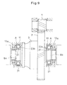
Fig. 9 is a sectional view of a gear support device. -
Fig. 10 is a sectional view of a differential. - Now the embodiment of the present invention is described. As shown in
Fig. 1 , the deep groove ball bearing A according to the invention comprises anouter race 11 formed with araceway groove 12 on its radially inner surface, aninner race 21 formed with araceway groove 22 on its radially outer surface,balls 31 disposed between theraceway grooves retainer 40 retaining theballs 31. - The
raceway groove 12 of theouter race 11 has first andsecond shoulders 13a and 13b on first and second sides of theraceway groove 12, respectively, of which the first shoulder 13a is higher than thesecond shoulder 13b. Theraceway groove 22 of theinner race 21 has first andsecond shoulders raceway groove 22, respectively, of which thesecond shoulder 23b is higher than thefirst shoulder 23a. - Here, the
lower shoulders - For the sake of description, the
higher shoulders 13a and 23b are hereinafter referred to as theshoulders 13a and 23b under thrust loads, and thelower shoulders shoulders - The ratio of the height H1 of the
shoulders 13a and 23b under thrust loads to the diameter d of theballs 31, i.e. ratio H1/d is determined within the range of 0.25-0.50. - As shown in
Figs. 1-3 , theretainer 40 comprises a firstsplit retainer member 41 and a secondsplit retainer member 42 inserted in the firstsplit retainer member 41. - As shown in
Fig. 5 , the firstsplit retainer member 41 comprises anannular member 43 made of a synthetic resin and having, on a first axial side thereof, a plurality of opposed pairs ofpocket claws 44, the respective pairs being circumferentially equidistantly spaced apart from each other. Acutout 45 is formed between each opposed pair ofpocket claws 44 which has a plan shape of a more than half-circle and extends through theannular member 43 in the thickness direction thereof. - As shown in
Fig. 1 , theannular member 43 has an inner diameter substantially equal to the pitch circle diameter (PCD) of theballs 31, and has an outer diameter in the range between the inner diameter of the higher shoulder 13a of theouter race 11 and the inner diameter of thelower shoulder 13b of theouter race 11. Thecutouts 45 have spherical inner surfaces extending along the outer peripheries of therespective balls 31. - The second
split retainer member 42 comprises anannular member 48 made of a synthetic resin and having, on a second axial side thereof, a plurality of opposed pairs ofpocket claws 49, the respective pairs being circumferentially equidistantly spaced apart from each other. Acutout 50 is formed between each opposed pair ofpocket claws 49 which has a plan shape of a more than half-circle and extends through theannular member 48 in the thickness direction thereof. - As shown in
Fig. 1 , theannular member 48 has an outer diameter substantially equal to the pitch circle diameter (PCD) of theballs 31, and has an inner diameter in the range between the outer diameter of thehigher shoulder 23b of theinner race 21 and the outer diameter of thelower shoulder 23a of theinner race 21. The secondsplit retainer member 42 can be inserted into the bearing with its side formed with thelower shoulder 23a first so as to be fitted into the firstsplit retainer member 41. Thecutouts 50 have spherical inner surfaces extending along the outer peripheries of therespective balls 31. - As shown in
Figs. 4 and 5 , coupling means X is provided between the firstsplit retainer member 41 and the secondsplit retainer member 42 for keeping the first and secondsplit retainer members split retainer member 42 inserted in the first axial side portion of the firstsplit retainer member 41, thereby defining a circular pocket by each opposed pair ofcutouts - The coupling means X comprises radially inwardly extending engaging
claws 46 formed on the free end portions ofbridges 43a defined between theadjacent cutouts 45, groove-shapedengaging recesses 47 formed on the radially inner surface of theannular member 43 so as to be axially aligned with the respectiveengaging claws 46, radially outwardly extendingengaging claws 51 formed on the free end portions ofbridges 48a defined between theadjacent cutouts 50, engagingrecesses 52 formed on the radially outer surface of theannular member 48 so as to be axially aligned with the respective engagingclaws 51. By the engagement between the engagingclaws 46 of the firstsplit retainer member 41 and the respective engagingrecesses 52 of the secondsplit retainer member 42 and by the engagement between the engagingclaws 51 of the secondsplit retainer member 42 and the respective engagingrecesses 47 of the firstsplit retainer member 41, the first and secondsplit retainer members - Since the first
split retainer member 41 and the secondsplit retainer member 42 are brought into contact with lubricating oil for lubricating the deep groove ball bearing, they should be made of an oil-resistant synthetic resin. Such oil-resistant synthetic resins include polyamide 46 (PA46), polyamide 66 (PA66) and polyphenylene sulfide (PPS). A suitable one may be selected from these resins according to the kind of lubricating oil. - In assembling this deep groove ball bearing, the
inner race 21 is inserted into theouter race 11, and theballs 31 are mounted between theraceway groove 22 of theinner race 21 and theraceway groove 12 of theouter race 11. - At this time, the
inner race 21 is radially moved relative to theouter race 11 until the radially outer surface of theinner race 21 partially contacts a portion of the radially inner surface of theouter race 11, thereby defining a crescent space between the inner and outer races at a position diametrically opposite to the contact portion between the inner and outer races, and theballs 31 are inserted into this crescent space from one side thereof. - When mounting the
balls 31, if the height H1 of the shoulder 13a under thrust loads of theouter race 11 or that of thehigher shoulder 23b of theinner race 21 should be unnecessarily high, it would be difficult to mount theballs 31. But in the embodiment of this invention, the ratio of the height H1 to the diameter d of theballs 31, i.e. H1/d is equal to or less than 0.50, theballs 31 can be reliably mounted between theouter race 11 and theinner race 21. - After mounting the
balls 31, theinner race 21 is moved back to the position where its center coincides with the center of theouter race 11, and theballs 31 are rearranged so as to be circumferentially equidistantly spaced apart from each other. In this state, the firstsplit retainer member 41 is inserted between theouter race 11 and theinner race 21 from the side of thelower shoulder 13b of theouter race 11 until theballs 31 fit into therespective cutouts 45 of thefirst retainer member 41. - The second
split retainer member 42 is inserted between theouter race 11 and theinner race 21 from the side of thelower shoulder 23a of theinner race 21 until theballs 31 fit into therespective cutouts 50 of the secondsplit retainer member 42 so that the second axial side portion of the secondsplit retainer member 42 is fitted in and engages the first axial side portion of the firstsplit retainer member 41. - By fitting the second
split retainer member 42 into the firstsplit retainer member 41, as shown inFigs. 1 and4 , the engagingclaws split retainer members recesses split retainer members - Thus, the deep groove ball bearing A can be easily assembled simply by mounting the
balls 31 between theraceway 12 of theouter race 11 and theraceway 22 of theinner race 21, and inserting firstsplit retainer member 41 and the secondsplit retainer member 42 between theouter race 11 and theinner race 21 from the respective opposite sides until the secondsplit retainer member 42 is fitted in the firstsplit retainer member 41. - In
Fig. 1 , thelower shoulders - If the
shoulders split retainer members shoulders retainer 40. - But if the
shoulders balls 31 may move onto theshoulders shoulder 13b of theouter race 11 is determined so that the ratio of the height H2 to the diameter d of theballs 31, i.e. H2/d is within the range of 0.09-0.50, and the height H3 of theshoulder 23a of theinner race 21 is determined such that the ratio of the height H3 to the diameter d of theballs 31, i.e. H3/d is within the range of 0.18-0.50. -
Fig. 9 shows how two of the deep groove ball bearings A of the above embodiment can be used to support thetubular portions differential case 3 shown inFig. 10 as shafts. The deep groove ball bearings A are positioned such that theshoulder 23b under thrust loads of theinner race 21 of each bearing A is located closer to the final drivengear 2. - In this gear support device, when torque is transmitted from the
final drive gear 1 and thedifferential case 3 is rotated in the direction in which the vehicle is driven in the forward direction, theouter race 11 and theinner race 21 rotate relative to each other, and theballs 31 revolve around the axis of the bearing, while rotating about their own axes. When theballs 31 revolve around the axis of the bearing, theretainer 40 is rotated together. Any lubricating oil disposed between theouter race 11 and theinner race 21 also rotates because it is in contact with theretainer 40. - At this time, since the first
split retainer member 41 and the secondsplit retainer member 42 have different outer diameters, their peripheral speeds are different from each other. Thus, lubricating oil that is in contact with the firstsplit retainer member 41 flows faster than lubricating oil that is in contact with the secondsplit retainer member 42. As a result, the lubricating oil flowing at a slower speed is drawn toward the lubricating oil flowing at a higher speed, thus producing pumping action in the bearing. Due to the pumping action, the lubricating oil flows in the direction of the arrows inFig. 1 , so that the interior of the bearing is forcibly lubricated. This improves lubricity of the deep groove ball bearings A. - In the deep groove ball bearing of the embodiment, each
ball 31 is embraced by the opposed pairs ofpocket claws cutout 45 of the firstsplit retainer member 41 and at the opening of eachcutout 50 of the secondsplit retainer member 42, respectively. The first and secondsplit retainer members pocket claws 44 formed on the firstsplit retainer member 41 extend in a direction opposite to the direction in which each opposed pair ofpocket claws 49 formed on the second split retainer member, with the engagingclaws split retainer member 41 and the secondsplit retainer member 42 axially inseparable from each other. Thus even if theballs 31 are moved faster or slower than theretainer 40 under large moment loads, theretainer 40 will never separate. - As shown in
Fig. 6(I) , the dimension δ1 of thecircumferential gap 60 defined between each of the engagingclaws recesses circumferential pocket gap 61 defined between eachball 31 and each of the correspondingcutouts balls 31 are moved faster or slower than theretainer 40 under large moment loads, and as a result, the firstsplit retainer member 41 and the secondsplit retainer member 42 rotate relative to each other, the engagingclaws recesses claws - As shown in
Fig. 6(II) , the dimension δ3 of theaxial gap 62 defined between each of the engagingclaws recesses axial pocket gap 63 defined between eachball 31 and each of the correspondingcutouts split retainer member 41 and the secondsplit retainer member 42 are moved axially away from each other under axial force, the inner surfaces of the opposed pairs ofpocket claws respective balls 31 first, thus preventing the engagingclaws recesses claws - With the deep groove ball bearings A mounted in position as shown in
Fig. 9 , when thedifferential case 3 rotates in the direction in which the vehicle moves forward, thrust force is applied to thedifferential case 3 due to the rotation of the final drivengear 2, which is a helical gear. The thrust force is supported by theshoulder 23b under thrust loads of theinner race 21 and the shoulder 13a under thrust loads of theouter race 11, of the deep groove ball bearing A on the left-hand side ofFig. 9 . - At this time, thrust force is also applied to the
balls 31. Thus, if theshoulder 23b under thrust loads of theinner race 21 and the shoulder 13a under thrust loads of theouter race 11 are unnecessarily low in height, theballs 31 may move onto theshoulders 13a and 23b, thus damaging the edges of theshoulders 13a and 23b. - In the embodiment, since the ratio of the height H1 of these shoulders to the diameter d of the
balls 31, i.e. H1/d is determined to be 0.25 or higher, it is possible to reliably prevent theballs 31 from moving onto theshoulders 13a and 23b. - A standard deep groove ball bearing 6208C as a comparative example and a deep groove ball bearing according to the present invention were prepared. The comparative example includes an inner race having an outer diameter of 53.1 mm, and an outer race having an inner diameter of 68.1 mm. The bearing according to the present invention is the same as the comparative example except that the shoulder under thrust loads of the inner race has an outer diameter of 56.6 mm instead of 53.1 mm of the corresponding shoulder of the comparative example, and that the shoulder under thrust loads of the outer race has an inner diameter of 65.5 mm instead of 68.1 mm of the corresponding shoulder of the comparative example. Permissible thrust loads were measured for the comparative example and the bearing according to the present invention. The permissible thrust load of the deep groove ball bearing according to this invention was higher by 305% than that of the deep groove ball bearing as the comparative example. Another deep groove ball bearing was prepared which is identical to the above bearing according to this invention except that the shoulder under no thrust loads (axial loads) of the inner race has an outer diameter 51.9 mm instead of the standard 53.1 mm, and that the shoulder under no axial loads of the outer race has an inner diameter of 70.4 mm instead of the standard 68.1 mm. When a basic static load Co was applied to this bearing, the balls never moved onto the shoulders under no axial loads.
- When the
differential case 3 rotates in the direction in which the vehicle moves backward, thrust force applied to thedifferential case 3 is supported by theshoulder 23b under thrust loads of theinner race 21 and the shoulder 13a under thrust loads of theouter race 11, of the deep groove ball bearing A on the right-hand side ofFig. 9 . In this case too, since the ratio of the height H1 of the shoulders under thrust loads to the diameter d of theballs 31 is 0.25 or higher, it is possible to reliably prevent theballs 31 from moving onto the shoulders. - In
Figs. 1 and5 , thecutouts annular members cutouts Figs. 1 and5 . For example, as shown inFig. 7 , the cutouts may have a plan shape of the letter U so that they form cylindrical pockets when the firstsplit retainer member 41 and the secondsplit retainer member 42 are fitted together. - In the arrangement of
Fig. 7 , as shown inFigs. 7 and 8 , the dimension δ5 of thecircumferential gap 64 defined between each of the engagingclaws recesses circumferential pocket gap 66 defined between eachball 31 and each of the correspondingcutouts balls 31 are moved faster or slower than theretainer 40 under large moment loads, and as a result, the firstsplit retainer member 41 and the secondsplit retainer member 42 rotate relative to each other, the engagingclaws recesses claws - In
Fig. 9 , thetubular portions differential case 3 are supported by the deep groove ball bearings A as shown inFig. 1 , respectively. But instead, only one of thetubular portions Fig. 1 , and the other of the tubular portions may be supported by a cylindrical roller bearing, an angular ball bearing or a tapered roller bearing. By supporting at least one of thetubular portions Fig. 1 , it is possible to reduce the torque loss compared to the case in which both tubular portions are supported by tapered roller bearings, thereby improving fuel economy. -
- 11.
- Outer race
- 12, 22.
- Raceway groove
- 13a, 13b, 23a, 23b.
- Shoulder
- 21.
- Inner race
- 31.
- Ball
- 40.
- Retainer
- 41.
- First split retainer member
- 42.
- Second split retainer member
- 43a.
- Bridge
- 44, 49.
- Pocket claw
- 45, 50.
- Cutout
- 46, 51.
- Engaging claw
- 47, 52.
- Engaging recess
- 48a.
- Bridge
- 60, 62, 64.
- Circumferential gap
- 61, 63, 65.
- Circumferential pocket gap
- X.
- Coupling means
Claims (12)
- A retainer made of a synthetic resin for use in a deep groove ball bearing, said retainer comprising a cylindrical first split retainer member made of a synthetic resin, and a cylindrical second split retainer member made of a synthetic resin and configured to be inserted in the first split retainer member, wherein the first split retainer member has a first axial side in which first cutouts are formed so as be circumferentially spaced apart from each other, and the second split retainer member has a second axial side in which second cutouts are formed so as be circumferentially spaced apart from each other, wherein each of the first cutouts and the corresponding second cutout form a circular pocket for receiving a ball of the deep groove ball bearing when the second split retainer member is inserted into the first split retainer member, said retainer further comprising a coupling means for keeping the split retainer members axially inseparable from each other with the first and second cutouts forming the pockets for receiving respective balls of the deep groove ball bearing.
- The retainer of claim 1, wherein the coupling means comprises first engaging claws radially inwardly protruding from each of bridges defined between the adjacent first cutouts of the first split retainer member, second engaging claws radially outwardly protruding from each of bridges defined between the adjacent second cutouts of the second split retainer member, first engaging recesses formed in a radially inner surface of the first split retainer member, and second engaging recesses formed in a radially outer surface of a second split retainer member, wherein first engaging claws are engageable in the respective second engaging recesses, and the second engaging claws are engageable in the respective first engaging recesses.
- The retainer of claim 2 wherein the first and second engaging claws are engageable in the respective second and first engaging recesses at three or more locations.
- The retainer of any of claims 1-3, wherein the first and second cutouts have a plan shape of a more than half-circle, with an opposed pair of pocket claws formed at an open end of each of the cutouts, and each have a spherical surface that extends along the outer periphery of the ball received therein.
- The retainer of claim 4, wherein a first circumferential gap is defined between each engaging claw and a corresponding engaging recess, and a second circumferential gap is defined between each of said pockets and the ball received therein, and wherein the first circumferential gap is larger than the second circumferential gap.
- The retainer of claim 4 or 5, wherein a first axial gap is defined between each engaging claw and a corresponding engaging recess, and a second axial gap is defined between each of said pockets and the ball received therein, and wherein the first axial gap is larger than the second axial gap.
- The retainer of any of claims 1-3, wherein the first and second cutouts have a plan shape of the letter U, whereby each pair of the first and second cutouts define a cylindrical pocket for receiving a ball of the deep groove ball bearing when the first and second split retainer members are coupled together.
- The retainer of claim 7 wherein a first circumferential gap is defined between each engaging claw and a corresponding engaging recess, and a second circumferential gap is defined between each of said pockets and the ball received therein, and wherein the first circumferential gap is larger than the second circumferential gap.
- The retainer of any of claims 1-8, wherein the first and second split retainer members are made of one of polyamide 46, polyamide 66 and polyphenylene sulfide.
- A deep groove ball bearing comprising an outer race formed with a raceway groove on a radially inner surface thereof, an inner race formed with a raceway groove on a radially outer surface thereof, balls mounted between the raceway groove of the outer race and the raceway groove of the inner race, and a retainer retaining the balls, wherein the retainer is the retainer of any of claims 1-9.
- The deep groove ball bearing of claim 10, wherein the outer race has a first shoulder on a first side of the raceway groove of the outer race and a second shoulder on a second side of the raceway groove of the outer race, wherein the inner race has a third shoulder on the first side of the raceway groove of the inner race and a fourth shoulder on the second side of the raceway groove of the inner race, wherein the first shoulder and the fourth shoulder have a height H1 which is higher than the height of the second and third shoulders, and wherein the ratio of the height H1 of the first and fourth shoulders to the diameter d of the balls (H1/d) is in the range of between 0.25 and 0.50.
- A gear support device comprising a shaft having a helical gear, and first and second bearings rotatably supporting the shaft on one and the other sides of the helical gear, respectively, whereby thrust load applied to the shaft while the helical gear is rotating in one direction is supported by the first bearing,
characterized in that the first and second bearing each comprise the deep groove ball bearing of claim 11, and that the fourth shoulder of the inner race of each of the deep groove ball bearings is located closer to the helical gear.
Applications Claiming Priority (3)
| Application Number | Priority Date | Filing Date | Title |
|---|---|---|---|
| JP2009152456A JP5348590B2 (en) | 2009-06-26 | 2009-06-26 | Deep groove ball bearing and gear support device |
| JP2009166411A JP5376310B2 (en) | 2009-07-15 | 2009-07-15 | Synthetic resin cage and deep groove ball bearing for deep groove ball bearings |
| PCT/JP2010/060364 WO2010150707A1 (en) | 2009-06-26 | 2010-06-18 | Synthetic resin holder for deep groove ball bearings, deep groove ball bearing, and gear supporting device |
Publications (3)
| Publication Number | Publication Date |
|---|---|
| EP2447557A1 true EP2447557A1 (en) | 2012-05-02 |
| EP2447557A4 EP2447557A4 (en) | 2013-11-06 |
| EP2447557B1 EP2447557B1 (en) | 2018-10-10 |
Family
ID=43386476
Family Applications (1)
| Application Number | Title | Priority Date | Filing Date |
|---|---|---|---|
| EP10792025.8A Not-in-force EP2447557B1 (en) | 2009-06-26 | 2010-06-18 | Retainer made of synthetic resin for use in a deep groove ball bearing; deep groove ball bearing; and gear support device |
Country Status (4)
| Country | Link |
|---|---|
| US (1) | US8939044B2 (en) |
| EP (1) | EP2447557B1 (en) |
| CN (1) | CN102803767B (en) |
| WO (1) | WO2010150707A1 (en) |
Cited By (1)
| Publication number | Priority date | Publication date | Assignee | Title |
|---|---|---|---|---|
| DE102012212056A1 (en) * | 2012-07-11 | 2014-01-16 | Schaeffler Technologies AG & Co. KG | Cage for angular contact ball bearings |
Families Citing this family (23)
| Publication number | Priority date | Publication date | Assignee | Title |
|---|---|---|---|---|
| IT1404769B1 (en) * | 2010-12-21 | 2013-11-29 | Skf Ab | RESTING BALL CAGE FOR BEARINGS AND RIGID BEARING UNIT |
| US8961023B2 (en) * | 2011-03-09 | 2015-02-24 | Ntn Corporation | Ball bearing retainer and ball bearing |
| JP5703894B2 (en) * | 2011-03-29 | 2015-04-22 | 日本精工株式会社 | Ball bearing |
| DE102012222799A1 (en) * | 2012-12-11 | 2014-06-12 | Schaeffler Technologies Gmbh & Co. Kg | Two-piece bearing cage with retaining claws and ball bearings, comprising such a two-part bearing cage |
| WO2014196428A1 (en) | 2013-06-06 | 2014-12-11 | Ntn株式会社 | Bearing component and rolling bearing |
| EP3006754B1 (en) | 2013-06-06 | 2021-09-08 | NTN Corporation | Bearing component and rolling bearing |
| US10156259B2 (en) | 2013-06-06 | 2018-12-18 | Ntn Corporation | Bearing component and rolling bearing |
| EP3006577B1 (en) | 2013-06-06 | 2019-07-17 | NTN Corporation | Bearing component and rolling bearing |
| JP6234137B2 (en) * | 2013-09-26 | 2017-11-22 | Ntn株式会社 | Deep groove ball bearing |
| WO2015141021A1 (en) * | 2014-03-19 | 2015-09-24 | 日本精工株式会社 | Angular ball bearing |
| US9773583B2 (en) * | 2014-04-24 | 2017-09-26 | Essex Group, Inc. | Continously transposed conductor |
| DE102014212267A1 (en) * | 2014-06-26 | 2015-12-31 | Aktiebolaget Skf | Rolling bearing cage |
| DE102015220363B4 (en) | 2015-10-20 | 2020-08-13 | Aktiebolaget Skf | Two-part bearing cage |
| CN108131396A (en) * | 2016-12-01 | 2018-06-08 | 舍弗勒技术股份两合公司 | bearing and retainer thereof |
| RU182343U1 (en) * | 2017-09-12 | 2018-08-15 | Общество с ограниченной ответственностью "Стратегическое бюро" | BALL BEARING RADIAL SINGLE ROW |
| RU182344U1 (en) * | 2017-09-12 | 2018-08-15 | Общество с ограниченной ответственностью "Стратегическое бюро" | BALL BEARING RADIAL SINGLE ROW |
| TWM573802U (en) * | 2018-02-26 | 2019-02-01 | 東培工業股份有限公司 | High speed ball bearing and ball retainer |
| DE102019104628B4 (en) * | 2019-02-25 | 2023-01-26 | Hiwin Technologies Corp. | Ball cage for a ball bearing |
| US10641331B1 (en) * | 2019-02-26 | 2020-05-05 | Hiwin Technologies Corp. | Ball cage for ball bearing |
| US10975912B1 (en) * | 2020-01-21 | 2021-04-13 | United Technologies Corporation | Roller bearing cage retention apparatus |
| EP3892888B1 (en) * | 2020-04-08 | 2025-06-11 | Volvo Car Corporation | A differential assembly |
| CN113983070B (en) * | 2020-07-27 | 2025-03-14 | 斯凯孚公司 | Deep groove ball bearings and differentials |
| CN114483792A (en) * | 2022-01-10 | 2022-05-13 | 中国航发哈尔滨轴承有限公司 | Retainer and bearing |
Family Cites Families (27)
| Publication number | Priority date | Publication date | Assignee | Title |
|---|---|---|---|---|
| US4451098A (en) | 1982-08-26 | 1984-05-29 | Usm Corporation | Ball separator assembly |
| GB2156912B (en) * | 1984-04-04 | 1987-09-03 | Skf Svenska Kullagerfab Ab | Cage for bearings |
| JPS63139323A (en) | 1986-12-02 | 1988-06-11 | Asahi Glass Co Ltd | Production of electrochromic element |
| JPH0247293Y2 (en) * | 1987-03-04 | 1990-12-12 | ||
| DE3738129A1 (en) | 1987-11-10 | 1989-05-18 | Kugelfischer G Schaefer & Co | Cage for ball bearings |
| JP3655386B2 (en) | 1996-03-29 | 2005-06-02 | Ntn株式会社 | Angular contact ball bearings |
| JPH102336A (en) * | 1996-04-16 | 1998-01-06 | Koyo Seiko Co Ltd | Retainer for bearing and manufacture therefor |
| JP2000145795A (en) | 1998-11-06 | 2000-05-26 | Ntn Corp | Deep groove ball bearing |
| US6715923B2 (en) * | 2000-01-06 | 2004-04-06 | Nsk Ltd. | Double row bearing device |
| JP4244518B2 (en) * | 2000-07-27 | 2009-03-25 | 株式会社ジェイテクト | Pulley unit |
| JP2002227846A (en) * | 2001-02-06 | 2002-08-14 | Minebea Co Ltd | Rolling bearing retainer |
| JP2003028163A (en) * | 2001-07-12 | 2003-01-29 | Minebea Co Ltd | Cage for ball bearing |
| JP2003097674A (en) * | 2001-09-21 | 2003-04-03 | Nsk Ltd | Assembly method of pulley device with built-in roller clutch |
| US7370741B2 (en) * | 2002-01-21 | 2008-05-13 | Nsk Ltd. | Engine start roller clutch-housed type rotation transmission device |
| JP2003254342A (en) * | 2002-03-04 | 2003-09-10 | Nsk Ltd | Ball bearing |
| CN100343539C (en) * | 2002-06-25 | 2007-10-17 | 日本精工株式会社 | Double row ball bearing with wheel bracket |
| JP4188666B2 (en) * | 2002-11-15 | 2008-11-26 | Ntn株式会社 | Resin cage for rolling bearings |
| DE602004023836D1 (en) * | 2003-05-28 | 2009-12-10 | Nsk Ltd | ROTATING DEVICE WITH SENSOR AND PROCEDURE EQUIPPED IN A ROLLER BEARING UNIT |
| US20050063627A1 (en) * | 2003-09-19 | 2005-03-24 | Ntn Corporation | Rolling element retainer and rolling bearing assembly using the same |
| JP2005180666A (en) * | 2003-12-24 | 2005-07-07 | Ntn Corp | Ball bearing cage and its ball bearing |
| JP4772381B2 (en) * | 2004-06-03 | 2011-09-14 | Ntn株式会社 | Synthetic resin cage and ball bearing using the cage |
| CN100453836C (en) * | 2004-06-03 | 2009-01-21 | Ntn株式会社 | Synthetic resin cage and ball bearing using the cage |
| US7771125B2 (en) * | 2004-06-07 | 2010-08-10 | Ntn Corporation | Retainer for rolling bearing, and rolling bearing |
| JP2006258172A (en) | 2005-03-16 | 2006-09-28 | Ntn Corp | Plastic resin cage |
| FR2883942B1 (en) | 2005-04-01 | 2008-09-12 | Snr Roulements Sa | REINFORCED RING BEARING COMPRISING A CAGE WITH A DEFLECTOR |
| JP4748373B2 (en) | 2006-11-14 | 2011-08-17 | 株式会社ジェイテクト | Roller bearing cage |
| BR122019024860B1 (en) * | 2008-06-13 | 2021-05-11 | Ntn Corporation | retainer, deep groove ball bearing and sealed bearing |
-
2010
- 2010-06-18 US US13/321,854 patent/US8939044B2/en not_active Expired - Fee Related
- 2010-06-18 CN CN201080027562.5A patent/CN102803767B/en not_active Expired - Fee Related
- 2010-06-18 WO PCT/JP2010/060364 patent/WO2010150707A1/en not_active Ceased
- 2010-06-18 EP EP10792025.8A patent/EP2447557B1/en not_active Not-in-force
Cited By (1)
| Publication number | Priority date | Publication date | Assignee | Title |
|---|---|---|---|---|
| DE102012212056A1 (en) * | 2012-07-11 | 2014-01-16 | Schaeffler Technologies AG & Co. KG | Cage for angular contact ball bearings |
Also Published As
| Publication number | Publication date |
|---|---|
| WO2010150707A1 (en) | 2010-12-29 |
| CN102803767B (en) | 2016-09-28 |
| CN102803767A (en) | 2012-11-28 |
| US8939044B2 (en) | 2015-01-27 |
| EP2447557B1 (en) | 2018-10-10 |
| EP2447557A4 (en) | 2013-11-06 |
| US20120060634A1 (en) | 2012-03-15 |
Similar Documents
| Publication | Publication Date | Title |
|---|---|---|
| EP2447557B1 (en) | Retainer made of synthetic resin for use in a deep groove ball bearing; deep groove ball bearing; and gear support device | |
| JP5348590B2 (en) | Deep groove ball bearing and gear support device | |
| EP1698789B1 (en) | Tapered roller bearing | |
| EP1746298B1 (en) | Tapered roller bearing | |
| EP3051160A1 (en) | Deep groove ball bearing | |
| EP2824365A2 (en) | Speed reducer | |
| JP2011007288A (en) | Deep groove ball bearing and gear support device | |
| JP2013092242A (en) | Retainer for deep groove ball bearing, deep groove ball bearing using the retainer, and bearing device | |
| JP2011080506A (en) | Deep groove ball bearing and gear supporting device | |
| CN113631820B (en) | Angular contact ball bearings with separable inner ring | |
| EP4116595A1 (en) | Cage and roller | |
| JP2011007284A (en) | Deep groove ball bearing and gear support device | |
| JP2013092241A (en) | Deep groove ball bearing and bearing device | |
| JP2013092240A (en) | Cage for deep groove ball bearing, deep groove ball bearing using the cage, and bearing device | |
| JP6537297B2 (en) | Deep groove ball bearings | |
| JP5005209B2 (en) | Tapered roller bearing | |
| JP2013072451A (en) | Deep groove ball bearing and bearing device | |
| JP5376310B2 (en) | Synthetic resin cage and deep groove ball bearing for deep groove ball bearings | |
| US8123414B2 (en) | Tapered roller bearing | |
| US10871191B2 (en) | Rolling bearing and bearing structure including same | |
| JP7708545B2 (en) | Separated inner ring angular contact ball bearing | |
| JP2006022821A (en) | Tapered roller bearing | |
| JP4994636B2 (en) | Tapered roller bearing | |
| CN1957186A (en) | Tapered roller bearing | |
| JP2006022823A (en) | Tapered roller bearing for transmission |
Legal Events
| Date | Code | Title | Description |
|---|---|---|---|
| PUAI | Public reference made under article 153(3) epc to a published international application that has entered the european phase |
Free format text: ORIGINAL CODE: 0009012 |
|
| 17P | Request for examination filed |
Effective date: 20120126 |
|
| AK | Designated contracting states |
Kind code of ref document: A1 Designated state(s): AL AT BE BG CH CY CZ DE DK EE ES FI FR GB GR HR HU IE IS IT LI LT LU LV MC MK MT NL NO PL PT RO SE SI SK SM TR |
|
| DAX | Request for extension of the european patent (deleted) | ||
| A4 | Supplementary search report drawn up and despatched |
Effective date: 20131007 |
|
| RIC1 | Information provided on ipc code assigned before grant |
Ipc: F16C 19/06 20060101ALI20130930BHEP Ipc: F16C 19/36 20060101ALI20130930BHEP Ipc: F16H 48/08 20060101ALI20130930BHEP Ipc: F16C 33/32 20060101ALI20130930BHEP Ipc: F16C 19/16 20060101ALI20130930BHEP Ipc: F16C 33/38 20060101ALI20130930BHEP Ipc: F16C 33/41 20060101ALI20130930BHEP Ipc: F16C 33/58 20060101AFI20130930BHEP Ipc: F16C 33/44 20060101ALI20130930BHEP |
|
| STAA | Information on the status of an ep patent application or granted ep patent |
Free format text: STATUS: EXAMINATION IS IN PROGRESS |
|
| 17Q | First examination report despatched |
Effective date: 20161121 |
|
| GRAP | Despatch of communication of intention to grant a patent |
Free format text: ORIGINAL CODE: EPIDOSNIGR1 |
|
| STAA | Information on the status of an ep patent application or granted ep patent |
Free format text: STATUS: GRANT OF PATENT IS INTENDED |
|
| INTG | Intention to grant announced |
Effective date: 20180124 |
|
| GRAJ | Information related to disapproval of communication of intention to grant by the applicant or resumption of examination proceedings by the epo deleted |
Free format text: ORIGINAL CODE: EPIDOSDIGR1 |
|
| STAA | Information on the status of an ep patent application or granted ep patent |
Free format text: STATUS: EXAMINATION IS IN PROGRESS |
|
| INTC | Intention to grant announced (deleted) | ||
| GRAP | Despatch of communication of intention to grant a patent |
Free format text: ORIGINAL CODE: EPIDOSNIGR1 |
|
| STAA | Information on the status of an ep patent application or granted ep patent |
Free format text: STATUS: GRANT OF PATENT IS INTENDED |
|
| INTG | Intention to grant announced |
Effective date: 20180531 |
|
| INTG | Intention to grant announced |
Effective date: 20180531 |
|
| GRAS | Grant fee paid |
Free format text: ORIGINAL CODE: EPIDOSNIGR3 |
|
| GRAA | (expected) grant |
Free format text: ORIGINAL CODE: 0009210 |
|
| STAA | Information on the status of an ep patent application or granted ep patent |
Free format text: STATUS: THE PATENT HAS BEEN GRANTED |
|
| AK | Designated contracting states |
Kind code of ref document: B1 Designated state(s): AL AT BE BG CH CY CZ DE DK EE ES FI FR GB GR HR HU IE IS IT LI LT LU LV MC MK MT NL NO PL PT RO SE SI SK SM TR |
|
| REG | Reference to a national code |
Ref country code: GB Ref legal event code: FG4D |
|
| REG | Reference to a national code |
Ref country code: CH Ref legal event code: EP Ref country code: AT Ref legal event code: REF Ref document number: 1051593 Country of ref document: AT Kind code of ref document: T Effective date: 20181015 |
|
| REG | Reference to a national code |
Ref country code: IE Ref legal event code: FG4D |
|
| REG | Reference to a national code |
Ref country code: DE Ref legal event code: R096 Ref document number: 602010054248 Country of ref document: DE |
|
| REG | Reference to a national code |
Ref country code: NL Ref legal event code: MP Effective date: 20181010 |
|
| REG | Reference to a national code |
Ref country code: LT Ref legal event code: MG4D |
|
| REG | Reference to a national code |
Ref country code: AT Ref legal event code: MK05 Ref document number: 1051593 Country of ref document: AT Kind code of ref document: T Effective date: 20181010 |
|
| PG25 | Lapsed in a contracting state [announced via postgrant information from national office to epo] |
Ref country code: NL Free format text: LAPSE BECAUSE OF FAILURE TO SUBMIT A TRANSLATION OF THE DESCRIPTION OR TO PAY THE FEE WITHIN THE PRESCRIBED TIME-LIMIT Effective date: 20181010 |
|
| PG25 | Lapsed in a contracting state [announced via postgrant information from national office to epo] |
Ref country code: ES Free format text: LAPSE BECAUSE OF FAILURE TO SUBMIT A TRANSLATION OF THE DESCRIPTION OR TO PAY THE FEE WITHIN THE PRESCRIBED TIME-LIMIT Effective date: 20181010 Ref country code: AT Free format text: LAPSE BECAUSE OF FAILURE TO SUBMIT A TRANSLATION OF THE DESCRIPTION OR TO PAY THE FEE WITHIN THE PRESCRIBED TIME-LIMIT Effective date: 20181010 Ref country code: IS Free format text: LAPSE BECAUSE OF FAILURE TO SUBMIT A TRANSLATION OF THE DESCRIPTION OR TO PAY THE FEE WITHIN THE PRESCRIBED TIME-LIMIT Effective date: 20190210 Ref country code: NO Free format text: LAPSE BECAUSE OF FAILURE TO SUBMIT A TRANSLATION OF THE DESCRIPTION OR TO PAY THE FEE WITHIN THE PRESCRIBED TIME-LIMIT Effective date: 20190110 Ref country code: BG Free format text: LAPSE BECAUSE OF FAILURE TO SUBMIT A TRANSLATION OF THE DESCRIPTION OR TO PAY THE FEE WITHIN THE PRESCRIBED TIME-LIMIT Effective date: 20190110 Ref country code: FI Free format text: LAPSE BECAUSE OF FAILURE TO SUBMIT A TRANSLATION OF THE DESCRIPTION OR TO PAY THE FEE WITHIN THE PRESCRIBED TIME-LIMIT Effective date: 20181010 Ref country code: LT Free format text: LAPSE BECAUSE OF FAILURE TO SUBMIT A TRANSLATION OF THE DESCRIPTION OR TO PAY THE FEE WITHIN THE PRESCRIBED TIME-LIMIT Effective date: 20181010 Ref country code: PL Free format text: LAPSE BECAUSE OF FAILURE TO SUBMIT A TRANSLATION OF THE DESCRIPTION OR TO PAY THE FEE WITHIN THE PRESCRIBED TIME-LIMIT Effective date: 20181010 Ref country code: HR Free format text: LAPSE BECAUSE OF FAILURE TO SUBMIT A TRANSLATION OF THE DESCRIPTION OR TO PAY THE FEE WITHIN THE PRESCRIBED TIME-LIMIT Effective date: 20181010 Ref country code: LV Free format text: LAPSE BECAUSE OF FAILURE TO SUBMIT A TRANSLATION OF THE DESCRIPTION OR TO PAY THE FEE WITHIN THE PRESCRIBED TIME-LIMIT Effective date: 20181010 |
|
| PG25 | Lapsed in a contracting state [announced via postgrant information from national office to epo] |
Ref country code: SE Free format text: LAPSE BECAUSE OF FAILURE TO SUBMIT A TRANSLATION OF THE DESCRIPTION OR TO PAY THE FEE WITHIN THE PRESCRIBED TIME-LIMIT Effective date: 20181010 Ref country code: AL Free format text: LAPSE BECAUSE OF FAILURE TO SUBMIT A TRANSLATION OF THE DESCRIPTION OR TO PAY THE FEE WITHIN THE PRESCRIBED TIME-LIMIT Effective date: 20181010 Ref country code: PT Free format text: LAPSE BECAUSE OF FAILURE TO SUBMIT A TRANSLATION OF THE DESCRIPTION OR TO PAY THE FEE WITHIN THE PRESCRIBED TIME-LIMIT Effective date: 20190210 Ref country code: GR Free format text: LAPSE BECAUSE OF FAILURE TO SUBMIT A TRANSLATION OF THE DESCRIPTION OR TO PAY THE FEE WITHIN THE PRESCRIBED TIME-LIMIT Effective date: 20190111 |
|
| REG | Reference to a national code |
Ref country code: DE Ref legal event code: R097 Ref document number: 602010054248 Country of ref document: DE |
|
| PG25 | Lapsed in a contracting state [announced via postgrant information from national office to epo] |
Ref country code: DK Free format text: LAPSE BECAUSE OF FAILURE TO SUBMIT A TRANSLATION OF THE DESCRIPTION OR TO PAY THE FEE WITHIN THE PRESCRIBED TIME-LIMIT Effective date: 20181010 Ref country code: CZ Free format text: LAPSE BECAUSE OF FAILURE TO SUBMIT A TRANSLATION OF THE DESCRIPTION OR TO PAY THE FEE WITHIN THE PRESCRIBED TIME-LIMIT Effective date: 20181010 Ref country code: IT Free format text: LAPSE BECAUSE OF FAILURE TO SUBMIT A TRANSLATION OF THE DESCRIPTION OR TO PAY THE FEE WITHIN THE PRESCRIBED TIME-LIMIT Effective date: 20181010 |
|
| PLBE | No opposition filed within time limit |
Free format text: ORIGINAL CODE: 0009261 |
|
| STAA | Information on the status of an ep patent application or granted ep patent |
Free format text: STATUS: NO OPPOSITION FILED WITHIN TIME LIMIT |
|
| PG25 | Lapsed in a contracting state [announced via postgrant information from national office to epo] |
Ref country code: SM Free format text: LAPSE BECAUSE OF FAILURE TO SUBMIT A TRANSLATION OF THE DESCRIPTION OR TO PAY THE FEE WITHIN THE PRESCRIBED TIME-LIMIT Effective date: 20181010 Ref country code: EE Free format text: LAPSE BECAUSE OF FAILURE TO SUBMIT A TRANSLATION OF THE DESCRIPTION OR TO PAY THE FEE WITHIN THE PRESCRIBED TIME-LIMIT Effective date: 20181010 Ref country code: RO Free format text: LAPSE BECAUSE OF FAILURE TO SUBMIT A TRANSLATION OF THE DESCRIPTION OR TO PAY THE FEE WITHIN THE PRESCRIBED TIME-LIMIT Effective date: 20181010 Ref country code: SK Free format text: LAPSE BECAUSE OF FAILURE TO SUBMIT A TRANSLATION OF THE DESCRIPTION OR TO PAY THE FEE WITHIN THE PRESCRIBED TIME-LIMIT Effective date: 20181010 |
|
| 26N | No opposition filed |
Effective date: 20190711 |
|
| PG25 | Lapsed in a contracting state [announced via postgrant information from national office to epo] |
Ref country code: SI Free format text: LAPSE BECAUSE OF FAILURE TO SUBMIT A TRANSLATION OF THE DESCRIPTION OR TO PAY THE FEE WITHIN THE PRESCRIBED TIME-LIMIT Effective date: 20181010 |
|
| PG25 | Lapsed in a contracting state [announced via postgrant information from national office to epo] |
Ref country code: MC Free format text: LAPSE BECAUSE OF FAILURE TO SUBMIT A TRANSLATION OF THE DESCRIPTION OR TO PAY THE FEE WITHIN THE PRESCRIBED TIME-LIMIT Effective date: 20181010 |
|
| REG | Reference to a national code |
Ref country code: CH Ref legal event code: PL |
|
| GBPC | Gb: european patent ceased through non-payment of renewal fee |
Effective date: 20190618 |
|
| REG | Reference to a national code |
Ref country code: BE Ref legal event code: MM Effective date: 20190630 |
|
| PG25 | Lapsed in a contracting state [announced via postgrant information from national office to epo] |
Ref country code: TR Free format text: LAPSE BECAUSE OF FAILURE TO SUBMIT A TRANSLATION OF THE DESCRIPTION OR TO PAY THE FEE WITHIN THE PRESCRIBED TIME-LIMIT Effective date: 20181010 |
|
| PG25 | Lapsed in a contracting state [announced via postgrant information from national office to epo] |
Ref country code: IE Free format text: LAPSE BECAUSE OF NON-PAYMENT OF DUE FEES Effective date: 20190618 Ref country code: GB Free format text: LAPSE BECAUSE OF NON-PAYMENT OF DUE FEES Effective date: 20190618 |
|
| PG25 | Lapsed in a contracting state [announced via postgrant information from national office to epo] |
Ref country code: LI Free format text: LAPSE BECAUSE OF NON-PAYMENT OF DUE FEES Effective date: 20190630 Ref country code: BE Free format text: LAPSE BECAUSE OF NON-PAYMENT OF DUE FEES Effective date: 20190630 Ref country code: LU Free format text: LAPSE BECAUSE OF NON-PAYMENT OF DUE FEES Effective date: 20190618 Ref country code: CH Free format text: LAPSE BECAUSE OF NON-PAYMENT OF DUE FEES Effective date: 20190630 |
|
| PG25 | Lapsed in a contracting state [announced via postgrant information from national office to epo] |
Ref country code: CY Free format text: LAPSE BECAUSE OF FAILURE TO SUBMIT A TRANSLATION OF THE DESCRIPTION OR TO PAY THE FEE WITHIN THE PRESCRIBED TIME-LIMIT Effective date: 20181010 |
|
| PG25 | Lapsed in a contracting state [announced via postgrant information from national office to epo] |
Ref country code: HU Free format text: LAPSE BECAUSE OF FAILURE TO SUBMIT A TRANSLATION OF THE DESCRIPTION OR TO PAY THE FEE WITHIN THE PRESCRIBED TIME-LIMIT; INVALID AB INITIO Effective date: 20100618 Ref country code: MT Free format text: LAPSE BECAUSE OF FAILURE TO SUBMIT A TRANSLATION OF THE DESCRIPTION OR TO PAY THE FEE WITHIN THE PRESCRIBED TIME-LIMIT Effective date: 20181010 |
|
| PGFP | Annual fee paid to national office [announced via postgrant information from national office to epo] |
Ref country code: DE Payment date: 20210525 Year of fee payment: 12 Ref country code: FR Payment date: 20210513 Year of fee payment: 12 |
|
| PG25 | Lapsed in a contracting state [announced via postgrant information from national office to epo] |
Ref country code: MK Free format text: LAPSE BECAUSE OF FAILURE TO SUBMIT A TRANSLATION OF THE DESCRIPTION OR TO PAY THE FEE WITHIN THE PRESCRIBED TIME-LIMIT Effective date: 20181010 |
|
| REG | Reference to a national code |
Ref country code: DE Ref legal event code: R119 Ref document number: 602010054248 Country of ref document: DE |
|
| PG25 | Lapsed in a contracting state [announced via postgrant information from national office to epo] |
Ref country code: FR Free format text: LAPSE BECAUSE OF NON-PAYMENT OF DUE FEES Effective date: 20220630 |
|
| PG25 | Lapsed in a contracting state [announced via postgrant information from national office to epo] |
Ref country code: DE Free format text: LAPSE BECAUSE OF NON-PAYMENT OF DUE FEES Effective date: 20230103 |