EP2447527A1 - Individual pitch control method for large wind generating set - Google Patents
Individual pitch control method for large wind generating set Download PDFInfo
- Publication number
- EP2447527A1 EP2447527A1 EP10791439A EP10791439A EP2447527A1 EP 2447527 A1 EP2447527 A1 EP 2447527A1 EP 10791439 A EP10791439 A EP 10791439A EP 10791439 A EP10791439 A EP 10791439A EP 2447527 A1 EP2447527 A1 EP 2447527A1
- Authority
- EP
- European Patent Office
- Prior art keywords
- pitch control
- output
- pitch
- load
- deviation
- Prior art date
- Legal status (The legal status is an assumption and is not a legal conclusion. Google has not performed a legal analysis and makes no representation as to the accuracy of the status listed.)
- Granted
Links
Images


Classifications
-
- F—MECHANICAL ENGINEERING; LIGHTING; HEATING; WEAPONS; BLASTING
- F03—MACHINES OR ENGINES FOR LIQUIDS; WIND, SPRING, OR WEIGHT MOTORS; PRODUCING MECHANICAL POWER OR A REACTIVE PROPULSIVE THRUST, NOT OTHERWISE PROVIDED FOR
- F03D—WIND MOTORS
- F03D7/00—Controlling wind motors
- F03D7/02—Controlling wind motors the wind motors having rotation axis substantially parallel to the air flow entering the rotor
- F03D7/04—Automatic control; Regulation
- F03D7/042—Automatic control; Regulation by means of an electrical or electronic controller
- F03D7/043—Automatic control; Regulation by means of an electrical or electronic controller characterised by the type of control logic
- F03D7/044—Automatic control; Regulation by means of an electrical or electronic controller characterised by the type of control logic with PID control
-
- F—MECHANICAL ENGINEERING; LIGHTING; HEATING; WEAPONS; BLASTING
- F03—MACHINES OR ENGINES FOR LIQUIDS; WIND, SPRING, OR WEIGHT MOTORS; PRODUCING MECHANICAL POWER OR A REACTIVE PROPULSIVE THRUST, NOT OTHERWISE PROVIDED FOR
- F03D—WIND MOTORS
- F03D7/00—Controlling wind motors
- F03D7/02—Controlling wind motors the wind motors having rotation axis substantially parallel to the air flow entering the rotor
- F03D7/022—Adjusting aerodynamic properties of the blades
- F03D7/0224—Adjusting blade pitch
-
- F—MECHANICAL ENGINEERING; LIGHTING; HEATING; WEAPONS; BLASTING
- F03—MACHINES OR ENGINES FOR LIQUIDS; WIND, SPRING, OR WEIGHT MOTORS; PRODUCING MECHANICAL POWER OR A REACTIVE PROPULSIVE THRUST, NOT OTHERWISE PROVIDED FOR
- F03D—WIND MOTORS
- F03D7/00—Controlling wind motors
- F03D7/02—Controlling wind motors the wind motors having rotation axis substantially parallel to the air flow entering the rotor
- F03D7/022—Adjusting aerodynamic properties of the blades
- F03D7/024—Adjusting aerodynamic properties of the blades of individual blades
-
- F—MECHANICAL ENGINEERING; LIGHTING; HEATING; WEAPONS; BLASTING
- F03—MACHINES OR ENGINES FOR LIQUIDS; WIND, SPRING, OR WEIGHT MOTORS; PRODUCING MECHANICAL POWER OR A REACTIVE PROPULSIVE THRUST, NOT OTHERWISE PROVIDED FOR
- F03D—WIND MOTORS
- F03D7/00—Controlling wind motors
- F03D7/02—Controlling wind motors the wind motors having rotation axis substantially parallel to the air flow entering the rotor
- F03D7/028—Controlling wind motors the wind motors having rotation axis substantially parallel to the air flow entering the rotor controlling wind motor output power
- F03D7/0292—Controlling wind motors the wind motors having rotation axis substantially parallel to the air flow entering the rotor controlling wind motor output power to reduce fatigue
-
- Y—GENERAL TAGGING OF NEW TECHNOLOGICAL DEVELOPMENTS; GENERAL TAGGING OF CROSS-SECTIONAL TECHNOLOGIES SPANNING OVER SEVERAL SECTIONS OF THE IPC; TECHNICAL SUBJECTS COVERED BY FORMER USPC CROSS-REFERENCE ART COLLECTIONS [XRACs] AND DIGESTS
- Y02—TECHNOLOGIES OR APPLICATIONS FOR MITIGATION OR ADAPTATION AGAINST CLIMATE CHANGE
- Y02E—REDUCTION OF GREENHOUSE GAS [GHG] EMISSIONS, RELATED TO ENERGY GENERATION, TRANSMISSION OR DISTRIBUTION
- Y02E10/00—Energy generation through renewable energy sources
- Y02E10/70—Wind energy
- Y02E10/72—Wind turbines with rotation axis in wind direction
Definitions
- the present invention relates to a control method for a large wind turbine generator system, and particularly to an individual pitch control method for a large wind turbine generator system.
- Wind shear, wind turbulence, tower shade effect, yaw deviation and other factors will cause unbalanced load on the rotor of the large wind turbine generator system.
- the diameter of the rotor increases, resulting in higher level of unbalance for the stress on the whole plane of the rotor and more significant unbalanced load on the rotor.
- the unbalanced load on the rotor will cause heavy fatigue load on important components such as pitch bearing, hub, main shaft, yaw bearing and tower.
- Theoretical analysis shows that the unbalanced load on the rotor may be reduced by individual pitch control of each blade according to conditions of the blade.
- a simple way to reduce the unbalanced load is measuring an azimuth of the rotor.
- wind speed variation of the rotor does not particularly depend on the azimuth of the rotor in practical wind regime, some specific influencing factors (wind shear, tower shade effect and inclination of the rotor) at a certain point on a blade vary independently with respect to the azimuth of the rotor under aerodynamic conditions. Theoretically, as long as these variations are constant, the pitch angle of each of the blades can be adjusted according to its functional relationship with the azimuth of the rotor, so as to reduce the load variation caused by the above factors.
- a correction based on wind direction may be made.
- a correction based on yaw deviation may also be performed if a wind direction signal of an engine room is used.
- the present invention provides an individual pitch control method for a large wind turbine generator system, in which the relatively heavy fatigue load is avoided by measuring the unbalanced load.
- the present invention provides an individual pitch control method for a large wind turbine generator system, which includes:
- the collective pitch control process includes controlling a rotating speed of a rotor based on a classic PI control and obtaining a collective pitch angle desired to be output for the collective pitch control
- the deviation pitch control process includes: obtaining a nodding load component and a yaw load component by Park transforming measured load values at root part of three blades; obtaining pitch angles desired to be output on d-axis and q-axis by respectively PI controlling the tilting load component and the yaw load component; and obtaining deviation pitch angles desired to be output for the deviation pitch control by Park inverse transforming pitch angles desired to be output on d-axis and q-axis;
- the step of controlling a rotating speed of a rotor based on a classic PI control and obtaining a collective pitch angle desired to be output for the collective pitch control includes:
- the deviation pitch control process includes:
- ⁇ c is the collective pitch angle desired to be output for the collective pitch control
- ⁇ 1 ⁇ ⁇ 2 ⁇ ⁇ 2 ⁇ are the deviation pitch angles desired to be output for the deviation pitch control
- ⁇ 1 , ⁇ 2 , ⁇ 3 are pitch angles desired to be output for the individual pitch control.
- ⁇ 4 is a natural frequency of a low-pass filter
- ⁇ 4 is a natural frequency of a low-pass filter
- the method further includes a step of notch filtering the nodding load component M tilt and the yaw load component M yaw according to the following Laplace formulae:
- M tiltf s M tilt s 1 + 2 ⁇ ⁇ 5 ⁇ s / ⁇ 5 + s 2 / ⁇ 5 2 1 + 2 ⁇ ⁇ 6 ⁇ s / ⁇ 6 + s 2 / ⁇ 6 2
- M yawf s M yaw s 1 + 2 ⁇ ⁇ 5 ⁇ s / ⁇ 5 + s 2 / ⁇ 5 2 1 + 2 ⁇ ⁇ 6 ⁇ s / ⁇ 6 + s 2 / ⁇ 6 2 ;
- M tilf is a post-filtering tilting load component
- M yawf is a post-filtering yaw load component
- ⁇ 5 and ⁇ 6 are natural frequencies of a notch filter
- ⁇ 5 and ⁇ 6 are damping ratios of the notch filter.
- the Park transformation is 3/2 Park transformation.
- w gf is a post-filtering generator rotating speed
- ⁇ 1 is a natural frequency of a low-pass filter
- ⁇ 1 is a damping ratio of the low-pass filter
- ⁇ 2 and ⁇ 3 are natural frequencies of a notch filter
- ⁇ 2 and ⁇ 3 are damping ratios of the notch filter.
- the load values ( M y 1 , M y 2 , M y 3 ) at the root part of the three blades are detected by an optical fiber load sensor mounted at the root part of the blades.
- the azimuth ⁇ of the rotor is detected by an incremental encoder mounted on a slip ring.
- the present invention has the following advantages: 1. the unbalanced load on the rotor can be reduced effectively, and the fatigue load on the pitch bearing, the main shaft, the hub, the yaw bearing and the tower can be reduced, thus the reliability of the device is improved and the service life of the device is prolonged; and 2. the yaw load M yaw , which reflects the error for facing wind direction, can be generated, so that the wind turbine generator system can be kept facing wind without using yaw drives in the wind turbine.
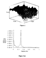
- Figure 1 shows an exemplary distribution of instantaneous wind speed, where X-axis represents the height, Y-axis represents the horizontal distance from the center of the hub, and Z-axis represents the wind speed;
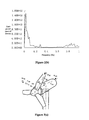
- Figure 2(a) shows a spectrogram of a blade load M y ;
- Figure 2(b) shows a spectrogram of a hub nodding load M tilt ;
- Figure 3 (a) shows a rotating coordinate system for analyzing the blade load
- Figure 3(b) shows a fixed coordinate system of the hub for analyzing the load of the hub, the tower and other static components of the wind turbine;
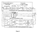
- FIG. 4 is a schematic diagram showing the principle of the individual pitch control in the present invention.
- Figure 5 is diagram shows transfer functions of the deviation controller.
- ⁇ is an average value of actual pitch angles of three blades
- ⁇ c is a collective pitch angle desired to be output for the collective pitch control
- ⁇ 1 ⁇ , ⁇ 2 ⁇ and ⁇ 3 ⁇ are deviation pitch angles desired to be output for the deviation pitch control
- ⁇ 1 , ⁇ 2 and ⁇ 3 are pitch angles desired to be output for the individual pitch control
- ⁇ 1 cm and ⁇ 2 cm are pitch angles desired to be output on d-axis and q-axis
- M y 1 , M y 2 and M y 3 are load values at the root part of the three blades
- M tilt and M yaw are load components on d-axis and q-axis
- ⁇ g is a generator rotating speed
- ⁇ ref is a rotor reference value
- ⁇ is a rotating speed deviation
- ⁇ is a azimuth of the rotor
- K c , K q and K d are gains of the PI controller
- the adopted individual pitch control is composed of a collective pitch control and a deviation pitch control, i.e., the outputs of the individual pitch control (the pitch angles desired to be output for the three blades) are obtained by adding the output of the collective pitch control (the common portion of the pitch angles desired to be output for the three blades) to the outputs of the deviation pitch control (the deviation portion of the pitch angles desired to be output for the three blades).
- the collective pitch control and the deviation pitch control are decomposed: the collective pitch control is used to implement the conventional pitch control function, in which the rotating speed of the rotor is controlled based on classical PI control; and the deviation pitch control is used to reduce the unbalanced loads on the rotor.
- the unbalanced loads M tilt and M yaw on the rotor are caused by the load fluctuation on the blades (which causes unbalanced stress on the three blades). If the 1P (nP represents n times of the rotating frequency of the rotor) harmonic component which is dominate in the blade load can be reduced by the deviation pitch control, the unbalanced loads on the rotor can be reduced effectively.
- the blade load M y is correlated to the pitch angle ⁇ and the relative wind speed ⁇ . In the case of a constant relative wind speed ⁇ , the blade load M y and the pitch angle ⁇ can be linearized to be linearly proportional nearby the working point, therefore regulating the pitch angle ⁇ in the same frequency (IP) is needed to reduce the 1P harmonic component in the blade load.
- the technical concept of the deviation pitch control is as follows: only the 1P harmonic component which is dominant in the load on the blade is reduced.
- the loads ( M y 1 , M y 2 , M y 3 ) on the three blades are transformed onto the d-q-axis in the fixed coordinate system of the hub by Park transformation which is commonly-used in electromechanics, so as to obtain the d-axis load component and the q-axis load component, which respectively represent the unbalanced loads M tilt and M yaw on the rotor.
- the d-axis load component and the q-axis load component are respectively subjected to classical PI control (the object value of the control is 0), so as to obtain the pitch angles ⁇ 1 cm ⁇ 2 cm desired to be output on d-axis and q-axis, which are Park inverse transformed into the deviation pitch angles ⁇ 1 ⁇ ⁇ 2 ⁇ ⁇ 2 ⁇ of 1P frequency variation in turn, thereby reducing the 1P harmonic component dominant in the blade load.
- Low-pass filter for lowering the sensitivity of the controller at relatively high frequency disturbance and notch filter for filtering 3P harmonic component are introduced into the deviation control, because once being amplified by the controller, the 3P harmonic component of the load in the fixed coordinate system of the hub may induce relatively heavy fatigue load on the wheel hub, the yaw bearing and the tower.
- an embodiment of the present invention provides an individual pitch control method for a large wind turbine generator system.
- the individual pitch control method further includes a deviation pitch control process, and the deviation pitch control process includes:
- FIG. 1 shows an exemplary distribution of the instantaneous wind speed. Because wind speed increases with increasing height due to wind shear, when the rotor is rotating, the wind speed experienced on vertically upward blade is larger than that on vertically downward blade, and the difference of wind speed will cause a wind shear force on the rotating blade. Furthermore, at a certain height, the wind speed can be divided into two components, with the first component being the average wind speed at this height, and the other component being the random wind speed caused by turbulence. The uneven distribution of the wind speed will cause unbalanced loads on the rotor.
- the individual pitch control is decomposed into the collective pitch control and the deviation pitch control.
- the classical PI controller is used to control the rotating speed of the rotor (the function of the conventional pitch control); and the deviation pitch control is used to reduce the unbalanced load on the rotor.
- the pitch angles desired to be output for the individual pitch control is the sum of the collective pitch angle desired to be output for the collective pitch control and the respective deviation pitch angles desired to be output for the deviation pitch control.
- the collective pitch control process includes: detecting a generator rotating speed ⁇ g with an encoder mounted on the generator, low-pass filtering and notch filtering the generator rotating speed ⁇ g , obtaining a rotating speed deviation ⁇ by subtracting a reference rotating speed ⁇ ref from the generator rotating speed ⁇ g , and obtaining the collective pitch angle ⁇ c , desired to be output for the collective pitch control after PI control.
- the low-pass filtering is used to lower the sensitivity of the controller at relatively high frequency
- the notch filtering is used to prevent unnecessary pitch control operation at the frequency close to 6P. Because of the nonlinearity of the pitch control system, the gain K c of the PI controller is determined from a look-up table, which is organized as a function of the average value ⁇ of the actual pitch angles of the three blades.
- FIG. 3(a) shows a rotating coordinate system which is generally used to analyze the blade load.
- ⁇ air density
- R is the radius of the rotor
- C my ( ⁇ i , ⁇ i ) is the bending moment coefficient of the blade
- ⁇ i is the tip speed ratio of the i th blade
- ⁇ i is the pitch angle of the i th blade
- ⁇ wi is the effective wind speed of the i th blade.
- the gravity load and the inertia load of the blade are relatively small and are negligible. It is assumed that the three blades of the wind turbine are arranged uniformly, with an angle of 120° between adjacent blade
- the blade load in the rotating coordinate system must be transformed into the fixed coordinate system of the hub (as shown in Figure 3(b) ).
- M d M q 2 3 ⁇ cos ⁇ cos ⁇ + 2 ⁇ ⁇ 3 cos ⁇ + 4 ⁇ ⁇ 3 sin ⁇ sin ⁇ + 2 ⁇ ⁇ 3 sin ⁇ + 4 ⁇ ⁇ 3 ⁇ M 1 M 2 M 3
- M 1 M 2 M 3 cos ⁇ sin ⁇ cos ⁇ + 2 ⁇ ⁇ 3 sin ⁇ + 2 ⁇ ⁇ 3 cos ⁇ + 4 ⁇ ⁇ 3 sin ⁇ + 4 ⁇ ⁇ 3 ⁇ M d M q
- ⁇ the azimuth of the rotor
- ⁇ ⁇ t
- M the standard load
- the 1P harmonic component in the blade load is Park transformed (with the formula (4)) into the 0P harmonic component of the nodding moment load and the 0P harmonic component of the yaw moment load in the fixed coordinate system of the hub, which are subjected to PI control in turn to obtain outputs ⁇ 1 cm ⁇ 2 cm and then subjected to Park inverse transformation (with the formula (5)) to obtain the pitch angles of the same frequency (1p) variation desired to be output, thereby reducing the 1P harmonic component in the blade load.
- the object of the PI controller is that the tilting moment load M tilt component and the yaw moment load M yaw in the fixed coordinate system of the hub, which are obtained by Park transformation of the 1P harmonic component in the blade load, are both 0, which means the reference input of the controller is 0. Because the deviation pitch control functions under the operating conditions when the wind speed is higher or lower than the rated wind speed, and the pitch control system is a nonlinear system, the gain of the PI controller and the amplitude-limiting magnitude in the amplitude limiting process both need to be determined using look-up table.
- the specific implementation is shown in Figure 5 .
- the load values ( M y 1, M y 2 , M y 3 ) at the root part of the three blades, which are detected by the optical fiber load sensor mounted at the root part, together with the azimuth ⁇ of the rotor, which is detected by the incremental encoder mounted on the slip ring, are transmitted to the main controller; in the main controller, the load values (M y 1, M y2 , M y 3 ) at the root part of the three blades are low-pass filtered and are then transformed into the M tilt load component and the M yaw load component by the Park transformation (the formula (5)); then the M tilt load component and the M yaw load component are notch filtered respectively to filter the 3P harmonic component, and are subjected to PI controlling of the PI controller, resulting in the outputs ⁇ 1 cm ⁇ 2 cm and then the deviation pitch angles ⁇ 1 ⁇ ⁇ 2 ⁇ ⁇ 2 ⁇ desired to be output are obtained by the Park inverse transformation (
Landscapes
- Engineering & Computer Science (AREA)
- Life Sciences & Earth Sciences (AREA)
- Sustainable Development (AREA)
- Sustainable Energy (AREA)
- Chemical & Material Sciences (AREA)
- Combustion & Propulsion (AREA)
- Mechanical Engineering (AREA)
- General Engineering & Computer Science (AREA)
- Physics & Mathematics (AREA)
- Fluid Mechanics (AREA)
- Wind Motors (AREA)
- Feedback Control In General (AREA)
Abstract
Description
- This application claims the benefit of priority to Chinese Patent Application No.
200910100064.8 - The present invention relates to a control method for a large wind turbine generator system, and particularly to an individual pitch control method for a large wind turbine generator system.
- Wind shear, wind turbulence, tower shade effect, yaw deviation and other factors will cause unbalanced load on the rotor of the large wind turbine generator system. As the unit capacity of the wind turbine generator system increases, the diameter of the rotor increases, resulting in higher level of unbalance for the stress on the whole plane of the rotor and more significant unbalanced load on the rotor. The unbalanced load on the rotor will cause heavy fatigue load on important components such as pitch bearing, hub, main shaft, yaw bearing and tower.
- Presently, a collective pitch control technique, in which blades are driven individually, i.e., three independent sets of pitch control executing mechanisms are given same location instructions, is used in almost all the large wind turbine generator systems with variable-speed pitch control of blades. However, such wind turbine generator systems can not eliminate the influence of the unbalanced load during the operation.
- Theoretical analysis shows that the unbalanced load on the rotor may be reduced by individual pitch control of each blade according to conditions of the blade.
- At present, a simple way to reduce the unbalanced load is measuring an azimuth of the rotor. Although wind speed variation of the rotor does not particularly depend on the azimuth of the rotor in practical wind regime, some specific influencing factors (wind shear, tower shade effect and inclination of the rotor) at a certain point on a blade vary independently with respect to the azimuth of the rotor under aerodynamic conditions. Theoretically, as long as these variations are constant, the pitch angle of each of the blades can be adjusted according to its functional relationship with the azimuth of the rotor, so as to reduce the load variation caused by the above factors. Although the effect of wind shear varies with the environment, a correction based on wind direction may be made. A correction based on yaw deviation may also be performed if a wind direction signal of an engine room is used.
- However, random variation caused by the wind turbulence is predominant in practical wind field, so it is difficult for the above approach to achieve ideal effect. Especially for a large blade, optimal effect can hardly be achieved because the suitable pitch angle varies with the location of the blade.
- If asymmetric loads can be measured continuously, the fatigue load on the blade, the hub, the main shaft, the yaw bearing and the tower can be reduced significantly by mitigating the asymmetry through individual pitch control. Nevertheless, individual pitch control is difficult to be implemented by classical control theory for its multiple variable inputs, multiple variable outputs, and system parameters with characteristics of nonlinearity, time variability and hysteresis, while complicated control strategy based on modern control theory for implementing the individual pitch control would greatly increase the calculation burden of the main controller and can hardly be put into practical application.
- To overcome the drawbacks that the unbalanced load on the rotor can not be effectively reduced by the existing pitch control method for the wind turbine generator system and relatively heavy fatigue load is prone to occur, the present invention provides an individual pitch control method for a large wind turbine generator system, in which the relatively heavy fatigue load is avoided by measuring the unbalanced load.
- The present invention provides an individual pitch control method for a large wind turbine generator system, which includes:
- decomposing an individual pitch control into a collective pitch control process and a deviation pitch control process, where the collective pitch control process includes controlling a rotating speed of a rotor based on a classic PI control and obtaining a collective pitch angle desired to be output for the collective pitch control; and the deviation pitch control process includes: obtaining a nodding load component and a yaw load component by Park transforming measured load values at root part of three blades; obtaining pitch angles desired to be output on d-axis and q-axis by respectively PI controlling the tilting load component and the yaw load component; and obtaining deviation pitch angles desired to be output for the deviation pitch control by Park inverse transforming pitch angles desired to be output on d-axis and q-axis;
- obtaining pitch angles desired to be output for the individual pitch control according to a sum of the collective pitch angle desired to be output for the collective pitch control and the respective deviation pitch angles desired to be output for the deviation pitch control; and
- implementing the pitch control by controlling operations of respective pitch control servo motors according to the pitch angles desired to be output for the individual pitch control.
- preferably, the step of controlling a rotating speed of a rotor based on a classic PI control and obtaining a collective pitch angle desired to be output for the collective pitch control includes:
- detecting a generator rotating speed ω g , obtaining a rotating speed deviation Δω by subtracting a reference rotating speed ω ref from the generator rotating speed ω g, and obtaining the collective pitch angle β c desired to be output for the collective pitch control according to the following Laplace formula:

- Preferably, the deviation pitch control process includes:
- 1) transmitting measured load values (M y1, M y2, M y3) at root part of the three blades and a azimuth ψ of the rotor to a main controller, performing a Park transformation on the load values (M y1, M y2, M y3) at root part of the three blades by the main controller, and obtaining the nodding load component Mtilt and the yaw load component Myaw ;
- 2) obtaining
pitch angles 


- 3) obtaining the deviation
pitch angles 
pitch angles 
- Preferably, the step of obtaining pitch angles desired to be output for the individual pitch control according to the collective pitch angle desired to be output for the collective pitch control and the deviation pitch angles desired to be output for the deviation pitch control is implemented according to the following formulae:

- where βc is the collective pitch angle desired to be output for the collective pitch control;

- Preferably, before the step of performing a Park transformation on the load values (M y1, M y2, M y3) at root part of the three blades by the main controller, the method further includes a step of low-pass filtering the load values at root part of the three blades according to the following Laplace formula:

- where i =1,2,3, Myi and Myif are respectively pre-filtering load value and post-filtering load value at the root part of the ith blade, ω4 is a natural frequency of a low-pass filter, and η4 is a natural frequency of a low-pass filter.
- Preferably, before the step of obtaining pitch angles desired to be output on d-axis and q-axis respectively according to the Laplace formulae, the method further includes a step of notch filtering the nodding load component Mtilt and the yaw load component Myaw according to the following Laplace formulae:

- where Mtilf is a post-filtering tilting load component, Myawf is a post-filtering yaw load component, ω5 and ω6 are natural frequencies of a notch filter, and η5 and η6 are damping ratios of the notch filter.
- Preferably, the Park transformation is 3/2 Park transformation.
- Preferably, before the step of obtaining a rotating speed deviation Δω by subtracting a reference rotating speed ω ref from the generator rotating speed ω g, the method further includes a step of filtering the generator rotating speed ω g according to the following Laplace formula:

- where wgf is a post-filtering generator rotating speed, ω1 is a natural frequency of a low-pass filter, η1 is a damping ratio of the low-pass filter, ω2 and ω3 are natural frequencies of a notch filter, and η2 and η3 are damping ratios of the notch filter.
- Preferably, the load values (M y1, M y2, M y3) at the root part of the three blades are detected by an optical fiber load sensor mounted at the root part of the blades.
- Preferably, the azimuth ψ of the rotor is detected by an incremental encoder mounted on a slip ring.
- The present invention has the following advantages: 1. the unbalanced load on the rotor can be reduced effectively, and the fatigue load on the pitch bearing, the main shaft, the hub, the yaw bearing and the tower can be reduced, thus the reliability of the device is improved and the service life of the device is prolonged; and 2. the yaw load Myaw, which reflects the error for facing wind direction, can be generated, so that the wind turbine generator system can be kept facing wind without using yaw drives in the wind turbine.
-
Figure 1 shows an exemplary distribution of instantaneous wind speed, where X-axis represents the height, Y-axis represents the horizontal distance from the center of the hub, and Z-axis represents the wind speed; -
Figure 2(a) shows a spectrogram of a blade load My ; -
Figure 2(b) shows a spectrogram of a hub nodding load Mtilt ; -
Figure 3 (a) shows a rotating coordinate system for analyzing the blade load; -
Figure 3(b) shows a fixed coordinate system of the hub for analyzing the load of the hub, the tower and other static components of the wind turbine; -
Figure 4 is a schematic diagram showing the principle of the individual pitch control in the present invention; and -
Figure 5 is diagram shows transfer functions of the deviation controller. - In the Figures, β is an average value of actual pitch angles of three blades, βc is a collective pitch angle desired to be output for the collective pitch control,


- The inventive concept and the basic principle of the present invention will be described hereinafter to facilitate the understanding and the implementing of the present invention by those skilled in the art.
- The technical concept of the present invention is as follows: the adopted individual pitch control is composed of a collective pitch control and a deviation pitch control, i.e., the outputs of the individual pitch control (the pitch angles desired to be output for the three blades) are obtained by adding the output of the collective pitch control (the common portion of the pitch angles desired to be output for the three blades) to the outputs of the deviation pitch control (the deviation portion of the pitch angles desired to be output for the three blades). Furthermore, the collective pitch control and the deviation pitch control are decomposed: the collective pitch control is used to implement the conventional pitch control function, in which the rotating speed of the rotor is controlled based on classical PI control; and the deviation pitch control is used to reduce the unbalanced loads on the rotor.
- The unbalanced loads Mtilt and Myaw on the rotor are caused by the load fluctuation on the blades (which causes unbalanced stress on the three blades). If the 1P (nP represents n times of the rotating frequency of the rotor) harmonic component which is dominate in the blade load can be reduced by the deviation pitch control, the unbalanced loads on the rotor can be reduced effectively. The blade load My is correlated to the pitch angle β and the relative wind speed ν. In the case of a constant relative wind speed ν, the blade load My and the pitch angle β can be linearized to be linearly proportional nearby the working point, therefore regulating the pitch angle β in the same frequency (IP) is needed to reduce the 1P harmonic component in the blade load.
- Hence, the technical concept of the deviation pitch control is as follows: only the 1P harmonic component which is dominant in the load on the blade is reduced. The loads (M y1, M y2, M y3) on the three blades are transformed onto the d-q-axis in the fixed coordinate system of the hub by Park transformation which is commonly-used in electromechanics, so as to obtain the d-axis load component and the q-axis load component, which respectively represent the unbalanced loads Mtilt and Myaw on the rotor. The d-axis load component and the q-axis load component are respectively subjected to classical PI control (the object value of the control is 0), so as to obtain the
pitch angles 
pitch angles 
- For better understanding of the above objects, features and advantages of the present invention, the embodiments of the present invention will be described in detail in conjunction with the drawings hereinafter.
- Referring to
Figures 1-5 , an embodiment of the present invention provides an individual pitch control method for a large wind turbine generator system. The individual pitch control method includes a collective pitch control process, and the collective pitch control process includes: detecting a generator rotating speed ω g, obtaining a rotating speed deviation Δω by subtracting a reference rotating speed ω ref from the generator rotating speed ω g , and obtaining the collective pitch angle β c desired to be output for the collective pitch control according to the following Laplace formula:
- The individual pitch control method further includes a deviation pitch control process, and the deviation pitch control process includes:
- 1) transmitting measured load values (M y1, M y2, M y3) at root part of the three blades and a azimuth ψ of the rotor to a main controller, performing a Park transformation on the load values (M y1, M y2, M y3) at root part of the three blades by the main controller, and obtaining the nodding load component Mtilt and the yaw load component Myaw ;
- 2) obtaining pitch angles


- 3) obtaining the deviation pitch angles


- obtaining the pitch angles (β 1 , β 2 , β 3) desired to be output for the individual pitch control according to the collective pitch angle β c desired to be output for the collective pitch control and the deviation pitch angles


- implementing the pitch control by controlling operations of respective pitch control servo motors according to the pitch angles (β1, β2, β3) desired to be output for the individual pitch control.
- The wind speed on the area swept by the rotor is variable in space and in time.
Figure 1 shows an exemplary distribution of the instantaneous wind speed. Because wind speed increases with increasing height due to wind shear, when the rotor is rotating, the wind speed experienced on vertically upward blade is larger than that on vertically downward blade, and the difference of wind speed will cause a wind shear force on the rotating blade. Furthermore, at a certain height, the wind speed can be divided into two components, with the first component being the average wind speed at this height, and the other component being the random wind speed caused by turbulence. The uneven distribution of the wind speed will cause unbalanced loads on the rotor. - Referring to
Figure 2(a) andFigure 2(b) , the spectrograms of the load My on the blade and the nodding load Mtilt on the hub of the wind turbine generator system under a certain operating condition are shown. Under this operating condition, the rotating speed of the rotor is 17.2rpm, i.e., 1P=0.287Hz. FromFigure 2(a) , it can be seen that except for the dominant harmonic component with the frequency of 1P, there are 2P, 3P, 4P and other harmonic components in the load on the blade. Under ideal wind regime, for a three-blade wind turbine, the load on the hub is mainly composed of 3P, 6P, ..., nP harmonic components, and other harmonic components are counteracted with each other. However, under practical wind regime, other harmonic components of the load on the hub are not are counteracted, so that unbalanced load will be induced (as shown inFigure 2(b) ). The unbalanced load will cause heavy fatigue load on the hub, the main shaft and the yaw bearing, which is harmful to the service life of the wind turbine. - Referring to
Figure 4 , the individual pitch control is decomposed into the collective pitch control and the deviation pitch control. In the collective pitch control, the classical PI controller is used to control the rotating speed of the rotor (the function of the conventional pitch control); and the deviation pitch control is used to reduce the unbalanced load on the rotor. The pitch angles desired to be output for the individual pitch control is the sum of the collective pitch angle desired to be output for the collective pitch control and the respective deviation pitch angles desired to be output for the deviation pitch control. - The collective pitch control process includes: detecting a generator rotating speed ω g with an encoder mounted on the generator, low-pass filtering and notch filtering the generator rotating speed ω g , obtaining a rotating speed deviation Δω by subtracting a reference rotating speed ω ref from the generator rotating speed ω g, and obtaining the collective pitch angle β c , desired to be output for the collective pitch control after PI control. The low-pass filtering is used to lower the sensitivity of the controller at relatively high frequency, and the notch filtering is used to prevent unnecessary pitch control operation at the frequency close to 6P. Because of the nonlinearity of the pitch control system, the gain Kc of the PI controller is determined from a look-up table, which is organized as a function of the average value β of the actual pitch angles of the three blades.
- The deviation pitch control will be described in detail hereinafter. Firstly, the load on blade of the wind turbine is analyzed.
Figure 3(a) shows a rotating coordinate system which is generally used to analyze the blade load. In the rotating coordinate system, the bending moment Myi at the root part of the ith blade is:
where ρ is air density; R is the radius of the rotor; Cmy (λi, βi ) is the bending moment coefficient of the blade; λ i is the tip speed ratio of the ith blade; β i is the pitch angle of the ith blade; and ν wi is the effective wind speed of the ith blade. The gravity load and the inertia load of the blade are relatively small and are negligible. It is assumed that the three blades of the wind turbine are arranged uniformly, with an angle of 120° between adjacent blades. - For calculating the load on the hub, the main shaft, the yaw bearing and the tower of the wind turbine, the blade load in the rotating coordinate system must be transformed into the fixed coordinate system of the hub (as shown in
Figure 3(b) ). With the coordinate transformation, the blade load is transformed into a load component on the y-axis and a load component on the x-axis in the fixed coordinate system of the hub, which respectively represent the physical meanings of the nodding moment load Mtilt and the yaw moment load Myaw , and the calculation formulae are as follows:

where w is the rotating speed of the wind turbine, i.e. 1P. - It can be seen from the formulae (2) and (3) that, the transformation of the blade load in the rotating coordinate system into the load in the fixed coordinate system of the hub can be implemented by the Park transformation which is commonly used in the motor vector control.
- The 3/2 Park transformation formula used herein is:

- And the 3/2 Park inverse transformation formula used herein is:

where ψ is the azimuth of the rotor, ψ = ωt; and M is the standard load. - The 1P harmonic component in the blade load is Park transformed (with the formula (4)) into the 0P harmonic component of the nodding moment load and the 0P harmonic component of the yaw moment load in the fixed coordinate system of the hub, which are subjected to PI control in turn to obtain outputs

- The specific implementation is shown in
Figure 5 . The load values (M y1, M y2, M y3) at the root part of the three blades, which are detected by the optical fiber load sensor mounted at the root part, together with the azimuth ψ of the rotor, which is detected by the incremental encoder mounted on the slip ring, are transmitted to the main controller; in the main controller, the load values (M y1, M y2, M y3) at the root part of the three blades are low-pass filtered and are then transformed into the Mtilt load component and the Myaw load component by the Park transformation (the formula (5)); then the Mtilt load component and the Myaw load component are notch filtered respectively to filter the 3P harmonic component, and are subjected to PI controlling of the PI controller, resulting in the outputs

- At last, the pitch angles

- One of the advantages of this technical solution is that the frequency required for the action of the newly added pitch control system is 1P, which is generally below 0.5Hz for the existing large wind turbine. Therefore, this technical solution is feasible for the pitch control executing mechanism adopted in the existing large wind turbine generator systems. Another advantage is that no modification to the physical structure of the wind turbine is needed for implementing the individual pitch control, since individually-driven collective pitch control is used in most of the existing large wind turbine generator systems.
- The above are merely the preferred embodiments of the present invention, and are not meant to limit the present invention in any form. Although the present invention is disclosed in preferred embodiments as mentioned above, the preferred embodiments are not meant to restrict the present invention. Numerous modifications, variations and equivalent alternatives can be made by those skilled in the art based on the above disclosed method and technical contents without departing from the scope of the technical solutions. Therefore, any content that dose not deviate form the technical solutions of the present invention, and any simple variations, equivalents and modifications made to the above embodiments based on the essence of the present invention fall in the scope of protection of the present invention.
Claims (10)
- An individual pitch control method for a large wind turbine generator system, comprising:decomposing an individual pitch control into a collective pitch control process and a deviation pitch control process, wherein the collective pitch control process comprises controlling a rotating speed of a rotor based on a classic PI control and obtaining a collective pitch angle desired to be output for the collective pitch control; and the deviation pitch control process comprises: obtaining a nodding load component and a yaw load component by Park transforming measured load values at root part of three blades; obtaining pitch angles desired to be output on d-axis and q-axis by respectively PI controlling the nodding load component and the yaw load component; and obtaining deviation pitch angles desired to be output for the deviation pitch control by Park inverse transforming pitch angles desired to be output on d-axis and q-axis;obtaining pitch angles desired to be output for the individual pitch control according to a sum of the collective pitch angle desired to be output for the collective pitch control and the respective deviation pitch angles desired to be output for the deviation pitch control; andimplementing the pitch control by controlling operations of respective pitch control servo motors according to the pitch angles desired to be output for the individual pitch control.
- The individual pitch control method for the large wind turbine generator system according to claim 1, wherein the step of controlling a rotating speed of a rotor based on a classic PI control and obtaining a collective pitch angle desired to be output for the collective pitch control comprises:detecting a generator rotating speed ω g, obtaining a rotating speed deviation Δω by subtracting a reference rotating speed ω ref from the generator rotating speed ω g , and obtaining the collective pitch angle β c desired to be output for the collective pitch control according to the following Laplace formula:

- The individual pitch control method for the large wind turbine generator system according to claim 1, wherein the deviation pitch control process comprises:1) transmitting measured load values (M y1, M y2, M y3) at root part of the three blades and a azimuth ψ of the rotor to a main controller, performing a Park transformation on the load values (M y1, M y2, M y3) at root part of the three blades by the main controller, and obtaining the nodding load component Mtilt and the yaw load component Myaw ;2) obtaining pitch angles


 3) obtaining the deviation pitch angles

- The individual pitch control method for the large wind turbine generator system according to claim 3, wherein obtaining pitch angles desired to be output for the individual pitch control according to the collective pitch angle desired to be output for the collective pitch control and the deviation pitch angles desired to be output for the deviation pitch control is implemented according to the following formulae:

where βc is the collective pitch angle desired to be output for the collective pitch control;
- The individual pitch control method for the large wind turbine generator system according to claim 3, wherein before the step of performing a Park transformation on the load values (M y1, M y2, M y3) at root part of the three blades by the main controller, the method further comprises a step of low-pass filtering the load values at root part of the three blades according to the following Laplace formula:

where i = 1,2,3, Myi and Myif are respectively pre-filtering load value and post-filtering load value at the root part of the ith blade, ω4 is a natural frequency of a low-pass filter, and η4 is a natural frequency of a low-pass filter. - The individual pitch control method for the large wind turbine generator system according to claim 3, wherein before the step of obtaining pitch angles desired to be output on d-axis and q-axis respectively according to the Laplace formulae, the method further comprises a step of notch filtering the nodding load component Mtilt and the yaw load component Myaw according to the following Laplace formulae:

where Mtilt is a post-filtering tilting load component, Myawf is a post-filtering yaw load component, ω5 and ω6 are natural frequencies of a notch filter, and η5 and η6 are damping ratios of the notch filter. - The individual pitch control method for the large wind turbine generator system according to claim 1 or 2, wherein the Park transformation is a 3/2 Park transformation.
- The individual pitch control method for the large wind turbine generator system according to claim 2, wherein before the step of obtaining a rotating speed deviation Δω by subtracting a reference rotating speed ω ref from the generator rotating speed ω g , the method further comprises a step of filtering the generator rotating speed ω g according to the following Laplace formula:

where ω gf is a post-filtering generator rotating speed, ω1 is a natural frequency of a low-pass filter, η1 is a damping ratio of the low-pass filter, ω2 and ω3 are natural frequencies of a notch filter, and η2 and η3 are damping ratios of the notch filter. - The individual pitch control method for the large wind turbine generator system according to claim 3, wherein the load values (M y1, M y2, M y3) at the root part of the three blades are detected by an optical fiber load sensor mounted at the root part of the blades.
- The individual pitch control method for the large wind turbine generator system according to claim 3, wherein the azimuth ψ of the rotor is detected by an incremental encoder mounted on a slip ring.
Applications Claiming Priority (2)
| Application Number | Priority Date | Filing Date | Title |
|---|---|---|---|
| CN2009101000648A CN101592127B (en) | 2009-06-22 | 2009-06-22 | Independent pitch control method for large wind turbine |
| PCT/CN2010/073598 WO2010148933A1 (en) | 2009-06-22 | 2010-06-07 | Individual pitch control method for large wind generating set |
Publications (3)
| Publication Number | Publication Date |
|---|---|
| EP2447527A1 true EP2447527A1 (en) | 2012-05-02 |
| EP2447527A4 EP2447527A4 (en) | 2016-03-23 |
| EP2447527B1 EP2447527B1 (en) | 2017-08-09 |
Family
ID=41406959
Family Applications (1)
| Application Number | Title | Priority Date | Filing Date |
|---|---|---|---|
| EP10791439.2A Active EP2447527B1 (en) | 2009-06-22 | 2010-06-07 | Individual pitch control method for large wind generating set |
Country Status (5)
| Country | Link |
|---|---|
| EP (1) | EP2447527B1 (en) |
| CN (1) | CN101592127B (en) |
| DK (1) | DK2447527T3 (en) |
| ES (1) | ES2645671T3 (en) |
| WO (1) | WO2010148933A1 (en) |
Cited By (18)
| Publication number | Priority date | Publication date | Assignee | Title |
|---|---|---|---|---|
| CN102619683A (en) * | 2011-01-30 | 2012-08-01 | 华锐风电科技(集团)股份有限公司 | Distributive control system for pitch control and yawing of wind power generator |
| EP2497946A1 (en) * | 2011-03-09 | 2012-09-12 | Siemens Aktiengesellschaft | Method and arrangement for detecting a blade pitch angle misalignment of a rotor blade system of a wind turbine |
| WO2012136279A3 (en) * | 2011-04-07 | 2013-04-04 | Siemens Aktiengesellschaft | Method of controlling pitch systems of a wind turbine |
| EP2784303A1 (en) * | 2013-03-27 | 2014-10-01 | Alstom Renovables España, S.L. | Method of operating a wind turbine |
| CN104428531A (en) * | 2012-06-08 | 2015-03-18 | 维斯塔斯风力系统集团公司 | A method of operating a wind turbine as well as a system suitable therefore |
| WO2017000569A1 (en) * | 2015-06-30 | 2017-01-05 | 中船重工(重庆)海装风电设备有限公司 | Equivalent variable pitch differential control method and apparatus |
| US9567978B2 (en) | 2014-10-27 | 2017-02-14 | General Electric Company | System and method for adaptive rotor imbalance control |
| WO2018184645A1 (en) * | 2017-04-05 | 2018-10-11 | Vestas Wind Systems A/S | Air density dependent turbine operation |
| DE102018130636A1 (en) * | 2018-12-03 | 2020-06-04 | Wobben Properties Gmbh | Method for operating a wind turbine |
| WO2020239177A1 (en) * | 2019-05-28 | 2020-12-03 | Vestas Wind Systems A/S | Reduction of edgewise vibrations using blade load signal |
| DE102019117934A1 (en) * | 2019-07-03 | 2021-01-07 | aerodyn product + license GmbH | Method for the aerodynamic power control of a wind energy installation having a plurality of rotor blades |
| KR102228726B1 (en) * | 2020-10-30 | 2021-03-17 | 한밭대학교 산학협력단 | Gain-scheduling method and apparatus of individual pitch controller in wind turbine systems |
| KR102228727B1 (en) * | 2020-11-10 | 2021-03-17 | 한밭대학교 산학협력단 | A method and apparatus of individual pitch control with blade mode notch filter in wind turbine systems |
| CN113027699A (en) * | 2019-12-25 | 2021-06-25 | 新疆金风科技股份有限公司 | Monitoring method, device and system of wind generating set |
| US11421652B2 (en) | 2018-05-09 | 2022-08-23 | Vestas Wind Systems A/S | Rotor control system for reducing structural vibrations based on m-blade transformation |
| WO2022242816A1 (en) * | 2021-05-17 | 2022-11-24 | Vestas Wind Systems A/S | Individual pitch control with unavailable blade load sensor |
| US20230204010A1 (en) * | 2020-05-04 | 2023-06-29 | Vestas Wind Systems A/S | Blade monitoring by actively promoting blade vibrations |
| US20240068443A1 (en) * | 2021-01-06 | 2024-02-29 | Vestas Wind Systems A/S | Reduction of edgewise vibrations using blade load signal |
Families Citing this family (37)
| Publication number | Priority date | Publication date | Assignee | Title |
|---|---|---|---|---|
| CN101592127B (en) * | 2009-06-22 | 2011-09-14 | 浙江运达风电股份有限公司 | Independent pitch control method for large wind turbine |
| CN101839806B (en) * | 2010-03-25 | 2012-05-23 | 三一电气有限责任公司 | Wind generating set and fatigue load monitoring system thereof |
| CN102102630B (en) * | 2010-10-26 | 2012-09-19 | 重庆大学 | Method for controlling independent variable propeller of variable speed variable propeller wind generating set |
| CN102080627B (en) * | 2011-03-03 | 2012-07-25 | 北京科诺伟业科技有限公司 | Safety chain unit for double-fed wind generating set |
| CN102182631A (en) * | 2011-05-03 | 2011-09-14 | 苏州能健电气有限公司 | Main control device of wind power generation equipment |
| CN102182633B (en) * | 2011-06-07 | 2013-07-24 | 浙江运达风电股份有限公司 | Independent paddle change control method and device of large-scale wind generator system |
| CN102506011B (en) * | 2011-12-30 | 2013-12-04 | 国电联合动力技术有限公司 | Synchronous correction method of pitch position of variable pitch wind generating set |
| CN102636367B (en) * | 2012-04-23 | 2014-08-27 | 浙江大学 | Multi-degree-of-freedom dynamic loading device for simulating wind power and ocean current load |
| CN102865192B (en) * | 2012-10-24 | 2016-02-03 | 南车株洲电力机车研究所有限公司 | A kind of pitch control method cutting down Wind turbines S.acus Linnaeus exact |
| CN103527405B (en) * | 2013-01-17 | 2016-01-13 | 成都阜特科技股份有限公司 | A kind of double-feedback aerogenerator group variable pitch control method |
| CN104214045B (en) * | 2013-05-30 | 2017-03-08 | 成都阜特科技股份有限公司 | The independent pitch of double-fed type speed-changing oar-changing wind power generating set is away from control method |
| CN104214044A (en) * | 2013-05-30 | 2014-12-17 | 成都阜特科技股份有限公司 | Independent variable pitch control method of double-fed variable-speed variable-pitch wind generating set |
| CN103742362B (en) * | 2014-01-15 | 2017-03-01 | 北京金风科创风电设备有限公司 | Independent variable pitch control system and method for direct-drive permanent magnet wind generating set |
| CN103835881B (en) * | 2014-03-05 | 2016-09-28 | 沈阳华创风能有限公司 | Independent pitch system based on electronic effective damping and change oar method |
| CN103925156B (en) * | 2014-05-04 | 2016-08-17 | 中船重工(重庆)海装风电设备有限公司 | A kind of wind generating set pitch control control method and system |
| CN104320030B (en) * | 2014-09-19 | 2017-06-27 | 北京天诚同创电气有限公司 | Control method and control device for rectification voltage of permanent magnet synchronous wind driven generator |
| CN104732060B (en) * | 2015-01-19 | 2017-09-29 | 湖南科技大学 | A kind of many heavy load ONLINE RECOGNITION methods of large-scale wind electricity turbines vane |
| CN105332856A (en) * | 2015-11-02 | 2016-02-17 | 浙江运达风电股份有限公司 | Wind turbine generator individual variable pitch control method based on measurement of main shaft loads of fixed coordinate system |
| CN105226716B (en) * | 2015-11-04 | 2017-07-21 | 浙江运达风电股份有限公司 | A kind of distributed double-fed wind power generator group automatic voltage control method |
| CN105986961B (en) * | 2016-04-28 | 2018-07-31 | 华北电力大学 | A kind of speed-changing oar-changing wind energy conversion system power optimization control method |
| CN106014857B (en) * | 2016-05-16 | 2019-11-15 | 国网冀北电力有限公司秦皇岛供电公司 | Independent pitch control method and device for suppressing wind turbine load |
| CN106773685A (en) * | 2016-12-08 | 2017-05-31 | 国家电网公司 | A kind of angle PI controller tuning methods for wind power yawing system |
| CN108443065A (en) * | 2018-03-06 | 2018-08-24 | 浙江运达风电股份有限公司 | A kind of Large-scale Wind Turbines independent feathering control optimization method |
| CN111379665B (en) * | 2018-12-27 | 2024-02-23 | 北京金风科创风电设备有限公司 | Pitch control method and system for wind turbines |
| CN110259637B (en) * | 2019-06-25 | 2021-03-23 | 中国船舶重工集团海装风电股份有限公司 | Pneumatic unbalance correction method, device and equipment for blades of wind generating set |
| CN110296046B (en) * | 2019-06-28 | 2020-05-12 | 湘电风能有限公司 | A wind turbine pitch control method |
| CN110439747B (en) * | 2019-08-02 | 2020-08-11 | 明阳智慧能源集团股份公司 | IPC control method for reducing vibration and load of wind power tower in left and right directions |
| CN113031527B (en) * | 2019-12-25 | 2023-05-30 | 新疆金风科技股份有限公司 | Multi-axis synchronous pitch control method, device and system |
| CN111075650B (en) * | 2019-12-30 | 2021-01-26 | 明阳智慧能源集团股份公司 | Independent pitch control method for wind turbine based on lidar feedforward wind measurement |
| CN112196735B (en) * | 2020-09-30 | 2023-07-21 | 重庆科凯前卫风电设备有限责任公司 | Variable pitch control method based on doubly-fed wind generator set |
| CN114109742B (en) * | 2021-11-22 | 2024-02-09 | 西安热工研究院有限公司 | Positioning and correcting method for unbalanced root cause of wind wheel of wind turbine caused by pitch angle deviation |
| ES3033839T3 (en) * | 2021-12-14 | 2025-08-08 | Vestas Wind Sys As | Wind turbine rotor blade pitch control for tower fatigue reduction |
| CN114483448B (en) * | 2022-01-18 | 2024-11-15 | 浙江大学 | Pitch limiting method for independent pitch control of large wind turbines |
| CN115126651B (en) * | 2022-06-06 | 2025-07-29 | 华锐风电科技(集团)股份有限公司 | Variable pitch control method based on hierarchical fuzzy and load control and wind generating set |
| CN116928022B (en) * | 2023-08-15 | 2026-03-24 | 明阳智慧能源集团股份公司 | A hierarchical fuzzy control method for two-bladed wind turbines based on IPC independent pitch technology |
| CN117191130B (en) * | 2023-09-27 | 2024-07-23 | 深圳市英博伟业科技有限公司 | Multi-scene online temperature and humidity monitoring method and system |
| CN119667200A (en) * | 2024-11-22 | 2025-03-21 | 三峡智控科技有限公司 | A method for calibrating anemometer based on blade load data |
Family Cites Families (8)
| Publication number | Priority date | Publication date | Assignee | Title |
|---|---|---|---|---|
| JPH06117353A (en) * | 1992-10-05 | 1994-04-26 | Yamaha Motor Co Ltd | Wind power generator |
| JP4340496B2 (en) * | 2003-08-11 | 2009-10-07 | 富士重工業株式会社 | Horizontal axis wind turbine and control method thereof |
| WO2005021962A1 (en) * | 2003-09-03 | 2005-03-10 | General Electric Company | Redundant blade pitch control system for a wind turbine and method for controlling a wind turbine |
| EP1978246A1 (en) * | 2007-04-04 | 2008-10-08 | Siemens Aktiengesellschaft | Method of reducing an unbalance in a wind turbine rotor and device for performing the method |
| JP4994947B2 (en) * | 2007-05-21 | 2012-08-08 | 三菱重工業株式会社 | Wind power generator and yaw rotation drive method for wind power generator |
| EP2037119B1 (en) * | 2007-09-12 | 2011-10-26 | Siemens Aktiengesellschaft | Controller for wind turbine yaw system and method for reducing the loads acting on such a yaw system |
| CN101404476A (en) * | 2008-10-15 | 2009-04-08 | 东南大学 | Operation control method for parallel variable-speed constant-frequency wind generator set |
| CN101592127B (en) * | 2009-06-22 | 2011-09-14 | 浙江运达风电股份有限公司 | Independent pitch control method for large wind turbine |
-
2009
- 2009-06-22 CN CN2009101000648A patent/CN101592127B/en active Active
-
2010
- 2010-06-07 EP EP10791439.2A patent/EP2447527B1/en active Active
- 2010-06-07 DK DK10791439.2T patent/DK2447527T3/en active
- 2010-06-07 ES ES10791439.2T patent/ES2645671T3/en active Active
- 2010-06-07 WO PCT/CN2010/073598 patent/WO2010148933A1/en not_active Ceased
Non-Patent Citations (1)
| Title |
|---|
| See references of WO2010148933A1 * |
Cited By (33)
| Publication number | Priority date | Publication date | Assignee | Title |
|---|---|---|---|---|
| CN102619683A (en) * | 2011-01-30 | 2012-08-01 | 华锐风电科技(集团)股份有限公司 | Distributive control system for pitch control and yawing of wind power generator |
| EP2497946A1 (en) * | 2011-03-09 | 2012-09-12 | Siemens Aktiengesellschaft | Method and arrangement for detecting a blade pitch angle misalignment of a rotor blade system of a wind turbine |
| WO2012136279A3 (en) * | 2011-04-07 | 2013-04-04 | Siemens Aktiengesellschaft | Method of controlling pitch systems of a wind turbine |
| CN104428531B (en) * | 2012-06-08 | 2018-05-22 | 维斯塔斯风力系统集团公司 | Method of operating a wind turbine and system suitable for said method |
| US9835137B2 (en) | 2012-06-08 | 2017-12-05 | Vestas Wind Systems A/S | Compensation for asymmetric load moment experienced by wind turbine rotor |
| US20150132129A1 (en) * | 2012-06-08 | 2015-05-14 | Vestas Wind Systems A/S | Method of operating a wind turbine as well as a system suitable therefore |
| CN104428531A (en) * | 2012-06-08 | 2015-03-18 | 维斯塔斯风力系统集团公司 | A method of operating a wind turbine as well as a system suitable therefore |
| US9476407B2 (en) | 2013-03-27 | 2016-10-25 | ALSTOM RENOVABLES ESPA{tilde over (E)}A, S.L. | Method of operating a wind turbine |
| EP2784303A1 (en) * | 2013-03-27 | 2014-10-01 | Alstom Renovables España, S.L. | Method of operating a wind turbine |
| US9567978B2 (en) | 2014-10-27 | 2017-02-14 | General Electric Company | System and method for adaptive rotor imbalance control |
| US10240585B2 (en) | 2015-06-30 | 2019-03-26 | Csic Haizhuang Windpower Co., Ltd. | Equivalent variable pitch differential control method and apparatus |
| WO2017000569A1 (en) * | 2015-06-30 | 2017-01-05 | 中船重工(重庆)海装风电设备有限公司 | Equivalent variable pitch differential control method and apparatus |
| US11300099B2 (en) | 2017-04-05 | 2022-04-12 | Vestas Wind Systems A/S | Air density dependent turbine operation |
| WO2018184645A1 (en) * | 2017-04-05 | 2018-10-11 | Vestas Wind Systems A/S | Air density dependent turbine operation |
| US11421652B2 (en) | 2018-05-09 | 2022-08-23 | Vestas Wind Systems A/S | Rotor control system for reducing structural vibrations based on m-blade transformation |
| DE102018130636A1 (en) * | 2018-12-03 | 2020-06-04 | Wobben Properties Gmbh | Method for operating a wind turbine |
| WO2020115018A1 (en) | 2018-12-03 | 2020-06-11 | Wobben Properties Gmbh | Method for operating a wind turbine |
| WO2020239177A1 (en) * | 2019-05-28 | 2020-12-03 | Vestas Wind Systems A/S | Reduction of edgewise vibrations using blade load signal |
| US12135012B2 (en) | 2019-05-28 | 2024-11-05 | Vestas Wind Systems A/S | Reduction of edgewise vibrations using blade load signal |
| CN114258459B (en) * | 2019-05-28 | 2024-09-13 | 维斯塔斯风力系统集团公司 | Using blade load signals to reduce edgewise vibration |
| CN114258459A (en) * | 2019-05-28 | 2022-03-29 | 维斯塔斯风力系统集团公司 | Reducing edgewise vibrations using blade load signals |
| DE102019117934A1 (en) * | 2019-07-03 | 2021-01-07 | aerodyn product + license GmbH | Method for the aerodynamic power control of a wind energy installation having a plurality of rotor blades |
| CN113027699B (en) * | 2019-12-25 | 2022-07-12 | 新疆金风科技股份有限公司 | Monitoring method, device and system of wind generating set |
| CN113027699A (en) * | 2019-12-25 | 2021-06-25 | 新疆金风科技股份有限公司 | Monitoring method, device and system of wind generating set |
| US20230204010A1 (en) * | 2020-05-04 | 2023-06-29 | Vestas Wind Systems A/S | Blade monitoring by actively promoting blade vibrations |
| US12331722B2 (en) * | 2020-05-04 | 2025-06-17 | Vestas Wind Systems A/S | Blade monitoring by actively promoting blade vibrations |
| WO2022092476A1 (en) * | 2020-10-30 | 2022-05-05 | 한밭대학교 산학협력단 | Wind turbine individual pitch control system and control method using gain-scheduling |
| KR102228726B1 (en) * | 2020-10-30 | 2021-03-17 | 한밭대학교 산학협력단 | Gain-scheduling method and apparatus of individual pitch controller in wind turbine systems |
| WO2022102895A1 (en) * | 2020-11-10 | 2022-05-19 | 한밭대학교 산학협력단 | Wind turbine individual pitch control system and control method having blade mode notch filter applied thereto |
| KR102228727B1 (en) * | 2020-11-10 | 2021-03-17 | 한밭대학교 산학협력단 | A method and apparatus of individual pitch control with blade mode notch filter in wind turbine systems |
| US20240068443A1 (en) * | 2021-01-06 | 2024-02-29 | Vestas Wind Systems A/S | Reduction of edgewise vibrations using blade load signal |
| US12173694B2 (en) * | 2021-01-06 | 2024-12-24 | Vestas Wind Systems A/S | Reduction of edgewise vibrations using blade load signal |
| WO2022242816A1 (en) * | 2021-05-17 | 2022-11-24 | Vestas Wind Systems A/S | Individual pitch control with unavailable blade load sensor |
Also Published As
| Publication number | Publication date |
|---|---|
| CN101592127B (en) | 2011-09-14 |
| DK2447527T3 (en) | 2017-11-27 |
| CN101592127A (en) | 2009-12-02 |
| EP2447527A4 (en) | 2016-03-23 |
| EP2447527B1 (en) | 2017-08-09 |
| WO2010148933A1 (en) | 2010-12-29 |
| ES2645671T3 (en) | 2017-12-07 |
Similar Documents
| Publication | Publication Date | Title |
|---|---|---|
| EP2447527B1 (en) | Individual pitch control method for large wind generating set | |
| US9617978B2 (en) | Method and device for preventing a lateral oscillation of a wind power installation | |
| EP3601789B1 (en) | System and method to manage torsional oscillation of a wind turbine tower | |
| EP3976959B1 (en) | Reduction of edgewise vibrations using blade load signal | |
| CN101400892B (en) | A method and control system for reducing the fatigue loads in the components of a wind turbine subjected to asymmetrical loading of the rotor plane | |
| CN112424470B (en) | Method and system for controlling a wind turbine to reduce nacelle vibrations | |
| Bossanyi et al. | Validation of individual pitch control by field tests on two-and three-bladed wind turbines | |
| EP2132437B1 (en) | Wind turbine with pitch control | |
| CN104214045B (en) | The independent pitch of double-fed type speed-changing oar-changing wind power generating set is away from control method | |
| CN100593641C (en) | Inverse system robust control method for variable pitch wind power generation system | |
| EP3794231B1 (en) | Wind turbine method for detection and control of whirling oscillations | |
| US8395273B2 (en) | Wind turbine generator, active damping method thereof, and windmill tower | |
| EP3976960B1 (en) | REDUCTION OF EDGE-WIDE VIBRATIONS BY MEANS OF A TORSION VIBRATION SIGNAL | |
| US20150285222A1 (en) | Wind turbine control method using an estimation of the incident wind speed | |
| CN104214044A (en) | Independent variable pitch control method of double-fed variable-speed variable-pitch wind generating set | |
| Kanev et al. | Exploring the limits in individual pitch control | |
| EP3794230B1 (en) | Method and system for controlling a wind turbine to reduce nacelle vibration | |
| EP2426352A2 (en) | Method for regulating the rotational speed of a wind turbine | |
| US20180003155A1 (en) | Equivalent variable pitch differential control method and apparatus | |
| US12612894B2 (en) | Controlling activation of individual pitch control of wind turbine rotor blades based on detected wind events | |
| WO2023088416A1 (en) | Controller for a wind turbine | |
| WO2023088432A1 (en) | Controller for a wind turbine | |
| Kallesøe et al. | Lateral tower load mitigation by generator torque control |
Legal Events
| Date | Code | Title | Description |
|---|---|---|---|
| PUAI | Public reference made under article 153(3) epc to a published international application that has entered the european phase |
Free format text: ORIGINAL CODE: 0009012 |
|
| 17P | Request for examination filed |
Effective date: 20111012 |
|
| AK | Designated contracting states |
Kind code of ref document: A1 Designated state(s): AL AT BE BG CH CY CZ DE DK EE ES FI FR GB GR HR HU IE IS IT LI LT LU LV MC MK MT NL NO PL PT RO SE SI SK SM TR |
|
| DAX | Request for extension of the european patent (deleted) | ||
| RA4 | Supplementary search report drawn up and despatched (corrected) |
Effective date: 20160224 |
|
| RIC1 | Information provided on ipc code assigned before grant |
Ipc: F03D 7/02 20060101ALI20160218BHEP Ipc: F03D 9/00 20160101ALI20160218BHEP Ipc: F03D 7/04 20060101ALI20160218BHEP Ipc: F03D 7/00 20060101AFI20160218BHEP |
|
| RAP1 | Party data changed (applicant data changed or rights of an application transferred) |
Owner name: ZHEJIANG WINDEY CO., LTD. |
|
| GRAP | Despatch of communication of intention to grant a patent |
Free format text: ORIGINAL CODE: EPIDOSNIGR1 |
|
| INTG | Intention to grant announced |
Effective date: 20170127 |
|
| GRAS | Grant fee paid |
Free format text: ORIGINAL CODE: EPIDOSNIGR3 |
|
| GRAA | (expected) grant |
Free format text: ORIGINAL CODE: 0009210 |
|
| AK | Designated contracting states |
Kind code of ref document: B1 Designated state(s): AL AT BE BG CH CY CZ DE DK EE ES FI FR GB GR HR HU IE IS IT LI LT LU LV MC MK MT NL NO PL PT RO SE SI SK SM TR |
|
| REG | Reference to a national code |
Ref country code: GB Ref legal event code: FG4D |
|
| REG | Reference to a national code |
Ref country code: CH Ref legal event code: EP Ref country code: AT Ref legal event code: REF Ref document number: 917156 Country of ref document: AT Kind code of ref document: T Effective date: 20170815 |
|
| REG | Reference to a national code |
Ref country code: IE Ref legal event code: FG4D |
|
| REG | Reference to a national code |
Ref country code: DE Ref legal event code: R096 Ref document number: 602010044315 Country of ref document: DE |
|
| REG | Reference to a national code |
Ref country code: DK Ref legal event code: T3 Effective date: 20171122 |
|
| REG | Reference to a national code |
Ref country code: ES Ref legal event code: FG2A Ref document number: 2645671 Country of ref document: ES Kind code of ref document: T3 Effective date: 20171207 |
|
| REG | Reference to a national code |
Ref country code: NL Ref legal event code: MP Effective date: 20170809 |
|
| REG | Reference to a national code |
Ref country code: LT Ref legal event code: MG4D |
|
| REG | Reference to a national code |
Ref country code: AT Ref legal event code: MK05 Ref document number: 917156 Country of ref document: AT Kind code of ref document: T Effective date: 20170809 |
|
| PG25 | Lapsed in a contracting state [announced via postgrant information from national office to epo] |
Ref country code: AT Free format text: LAPSE BECAUSE OF FAILURE TO SUBMIT A TRANSLATION OF THE DESCRIPTION OR TO PAY THE FEE WITHIN THE PRESCRIBED TIME-LIMIT Effective date: 20170809 Ref country code: NL Free format text: LAPSE BECAUSE OF FAILURE TO SUBMIT A TRANSLATION OF THE DESCRIPTION OR TO PAY THE FEE WITHIN THE PRESCRIBED TIME-LIMIT Effective date: 20170809 Ref country code: LT Free format text: LAPSE BECAUSE OF FAILURE TO SUBMIT A TRANSLATION OF THE DESCRIPTION OR TO PAY THE FEE WITHIN THE PRESCRIBED TIME-LIMIT Effective date: 20170809 Ref country code: NO Free format text: LAPSE BECAUSE OF FAILURE TO SUBMIT A TRANSLATION OF THE DESCRIPTION OR TO PAY THE FEE WITHIN THE PRESCRIBED TIME-LIMIT Effective date: 20171109 Ref country code: HR Free format text: LAPSE BECAUSE OF FAILURE TO SUBMIT A TRANSLATION OF THE DESCRIPTION OR TO PAY THE FEE WITHIN THE PRESCRIBED TIME-LIMIT Effective date: 20170809 Ref country code: FI Free format text: LAPSE BECAUSE OF FAILURE TO SUBMIT A TRANSLATION OF THE DESCRIPTION OR TO PAY THE FEE WITHIN THE PRESCRIBED TIME-LIMIT Effective date: 20170809 Ref country code: SE Free format text: LAPSE BECAUSE OF FAILURE TO SUBMIT A TRANSLATION OF THE DESCRIPTION OR TO PAY THE FEE WITHIN THE PRESCRIBED TIME-LIMIT Effective date: 20170809 |
|
| PG25 | Lapsed in a contracting state [announced via postgrant information from national office to epo] |
Ref country code: BG Free format text: LAPSE BECAUSE OF FAILURE TO SUBMIT A TRANSLATION OF THE DESCRIPTION OR TO PAY THE FEE WITHIN THE PRESCRIBED TIME-LIMIT Effective date: 20171109 Ref country code: PL Free format text: LAPSE BECAUSE OF FAILURE TO SUBMIT A TRANSLATION OF THE DESCRIPTION OR TO PAY THE FEE WITHIN THE PRESCRIBED TIME-LIMIT Effective date: 20170809 Ref country code: GR Free format text: LAPSE BECAUSE OF FAILURE TO SUBMIT A TRANSLATION OF THE DESCRIPTION OR TO PAY THE FEE WITHIN THE PRESCRIBED TIME-LIMIT Effective date: 20171110 Ref country code: LV Free format text: LAPSE BECAUSE OF FAILURE TO SUBMIT A TRANSLATION OF THE DESCRIPTION OR TO PAY THE FEE WITHIN THE PRESCRIBED TIME-LIMIT Effective date: 20170809 Ref country code: IS Free format text: LAPSE BECAUSE OF FAILURE TO SUBMIT A TRANSLATION OF THE DESCRIPTION OR TO PAY THE FEE WITHIN THE PRESCRIBED TIME-LIMIT Effective date: 20171209 |
|
| PG25 | Lapsed in a contracting state [announced via postgrant information from national office to epo] |
Ref country code: CZ Free format text: LAPSE BECAUSE OF FAILURE TO SUBMIT A TRANSLATION OF THE DESCRIPTION OR TO PAY THE FEE WITHIN THE PRESCRIBED TIME-LIMIT Effective date: 20170809 Ref country code: RO Free format text: LAPSE BECAUSE OF FAILURE TO SUBMIT A TRANSLATION OF THE DESCRIPTION OR TO PAY THE FEE WITHIN THE PRESCRIBED TIME-LIMIT Effective date: 20170809 |
|
| REG | Reference to a national code |
Ref country code: DE Ref legal event code: R097 Ref document number: 602010044315 Country of ref document: DE |
|
| PG25 | Lapsed in a contracting state [announced via postgrant information from national office to epo] |
Ref country code: SK Free format text: LAPSE BECAUSE OF FAILURE TO SUBMIT A TRANSLATION OF THE DESCRIPTION OR TO PAY THE FEE WITHIN THE PRESCRIBED TIME-LIMIT Effective date: 20170809 Ref country code: SM Free format text: LAPSE BECAUSE OF FAILURE TO SUBMIT A TRANSLATION OF THE DESCRIPTION OR TO PAY THE FEE WITHIN THE PRESCRIBED TIME-LIMIT Effective date: 20170809 Ref country code: EE Free format text: LAPSE BECAUSE OF FAILURE TO SUBMIT A TRANSLATION OF THE DESCRIPTION OR TO PAY THE FEE WITHIN THE PRESCRIBED TIME-LIMIT Effective date: 20170809 Ref country code: IT Free format text: LAPSE BECAUSE OF FAILURE TO SUBMIT A TRANSLATION OF THE DESCRIPTION OR TO PAY THE FEE WITHIN THE PRESCRIBED TIME-LIMIT Effective date: 20170809 |
|
| PLBE | No opposition filed within time limit |
Free format text: ORIGINAL CODE: 0009261 |
|
| STAA | Information on the status of an ep patent application or granted ep patent |
Free format text: STATUS: NO OPPOSITION FILED WITHIN TIME LIMIT |
|
| 26N | No opposition filed |
Effective date: 20180511 |
|
| PG25 | Lapsed in a contracting state [announced via postgrant information from national office to epo] |
Ref country code: SI Free format text: LAPSE BECAUSE OF FAILURE TO SUBMIT A TRANSLATION OF THE DESCRIPTION OR TO PAY THE FEE WITHIN THE PRESCRIBED TIME-LIMIT Effective date: 20170809 |
|
| REG | Reference to a national code |
Ref country code: CH Ref legal event code: PL |
|
| REG | Reference to a national code |
Ref country code: BE Ref legal event code: MM Effective date: 20180630 |
|
| REG | Reference to a national code |
Ref country code: IE Ref legal event code: MM4A |
|
| PG25 | Lapsed in a contracting state [announced via postgrant information from national office to epo] |
Ref country code: LU Free format text: LAPSE BECAUSE OF NON-PAYMENT OF DUE FEES Effective date: 20180607 Ref country code: MC Free format text: LAPSE BECAUSE OF FAILURE TO SUBMIT A TRANSLATION OF THE DESCRIPTION OR TO PAY THE FEE WITHIN THE PRESCRIBED TIME-LIMIT Effective date: 20170809 |
|
| PG25 | Lapsed in a contracting state [announced via postgrant information from national office to epo] |
Ref country code: LI Free format text: LAPSE BECAUSE OF NON-PAYMENT OF DUE FEES Effective date: 20180630 Ref country code: FR Free format text: LAPSE BECAUSE OF NON-PAYMENT OF DUE FEES Effective date: 20180630 Ref country code: IE Free format text: LAPSE BECAUSE OF NON-PAYMENT OF DUE FEES Effective date: 20180607 Ref country code: CH Free format text: LAPSE BECAUSE OF NON-PAYMENT OF DUE FEES Effective date: 20180630 |
|
| PG25 | Lapsed in a contracting state [announced via postgrant information from national office to epo] |
Ref country code: BE Free format text: LAPSE BECAUSE OF NON-PAYMENT OF DUE FEES Effective date: 20180630 |
|
| PG25 | Lapsed in a contracting state [announced via postgrant information from national office to epo] |
Ref country code: MT Free format text: LAPSE BECAUSE OF NON-PAYMENT OF DUE FEES Effective date: 20180607 |
|
| PG25 | Lapsed in a contracting state [announced via postgrant information from national office to epo] |
Ref country code: TR Free format text: LAPSE BECAUSE OF FAILURE TO SUBMIT A TRANSLATION OF THE DESCRIPTION OR TO PAY THE FEE WITHIN THE PRESCRIBED TIME-LIMIT Effective date: 20170809 |
|
| PG25 | Lapsed in a contracting state [announced via postgrant information from national office to epo] |
Ref country code: HU Free format text: LAPSE BECAUSE OF FAILURE TO SUBMIT A TRANSLATION OF THE DESCRIPTION OR TO PAY THE FEE WITHIN THE PRESCRIBED TIME-LIMIT; INVALID AB INITIO Effective date: 20100607 Ref country code: PT Free format text: LAPSE BECAUSE OF FAILURE TO SUBMIT A TRANSLATION OF THE DESCRIPTION OR TO PAY THE FEE WITHIN THE PRESCRIBED TIME-LIMIT Effective date: 20170809 |
|
| PG25 | Lapsed in a contracting state [announced via postgrant information from national office to epo] |
Ref country code: CY Free format text: LAPSE BECAUSE OF FAILURE TO SUBMIT A TRANSLATION OF THE DESCRIPTION OR TO PAY THE FEE WITHIN THE PRESCRIBED TIME-LIMIT Effective date: 20170809 Ref country code: MK Free format text: LAPSE BECAUSE OF NON-PAYMENT OF DUE FEES Effective date: 20170809 |
|
| PG25 | Lapsed in a contracting state [announced via postgrant information from national office to epo] |
Ref country code: AL Free format text: LAPSE BECAUSE OF FAILURE TO SUBMIT A TRANSLATION OF THE DESCRIPTION OR TO PAY THE FEE WITHIN THE PRESCRIBED TIME-LIMIT Effective date: 20170809 |
|
| PGFP | Annual fee paid to national office [announced via postgrant information from national office to epo] |
Ref country code: DK Payment date: 20250627 Year of fee payment: 16 |
|
| PGFP | Annual fee paid to national office [announced via postgrant information from national office to epo] |
Ref country code: ES Payment date: 20250714 Year of fee payment: 16 |
|
| PGFP | Annual fee paid to national office [announced via postgrant information from national office to epo] |
Ref country code: DE Payment date: 20250711 Year of fee payment: 16 |
|
| PGFP | Annual fee paid to national office [announced via postgrant information from national office to epo] |
Ref country code: GB Payment date: 20250723 Year of fee payment: 16 |