EP2447466A2 - Downhole flow device with erosion resistant and pressure assisted metal seal - Google Patents
Downhole flow device with erosion resistant and pressure assisted metal seal Download PDFInfo
- Publication number
- EP2447466A2 EP2447466A2 EP10192151A EP10192151A EP2447466A2 EP 2447466 A2 EP2447466 A2 EP 2447466A2 EP 10192151 A EP10192151 A EP 10192151A EP 10192151 A EP10192151 A EP 10192151A EP 2447466 A2 EP2447466 A2 EP 2447466A2
- Authority
- EP
- European Patent Office
- Prior art keywords
- sleeve
- seal
- flow
- sliding sleeve
- ports
- Prior art date
- Legal status (The legal status is an assumption and is not a legal conclusion. Google has not performed a legal analysis and makes no representation as to the accuracy of the status listed.)
- Granted
Links
- 230000003628 erosive effect Effects 0.000 title abstract description 21
- 239000002184 metal Substances 0.000 title description 6
- 238000012856 packing Methods 0.000 claims description 17
- 230000007246 mechanism Effects 0.000 claims description 7
- 239000012530 fluid Substances 0.000 abstract description 26
- 238000007789 sealing Methods 0.000 abstract description 17
- 230000006378 damage Effects 0.000 abstract description 12
- 238000005299 abrasion Methods 0.000 abstract 1
- 241000283216 Phocidae Species 0.000 description 75
- 241000282472 Canis lupus familiaris Species 0.000 description 15
- 230000000694 effects Effects 0.000 description 8
- 238000000034 method Methods 0.000 description 6
- 238000004519 manufacturing process Methods 0.000 description 5
- 230000007423 decrease Effects 0.000 description 2
- 230000001627 detrimental effect Effects 0.000 description 2
- 238000002347 injection Methods 0.000 description 2
- 239000007924 injection Substances 0.000 description 2
- 238000003825 pressing Methods 0.000 description 2
- 230000004913 activation Effects 0.000 description 1
- 230000004075 alteration Effects 0.000 description 1
- 238000010420 art technique Methods 0.000 description 1
- 230000004888 barrier function Effects 0.000 description 1
- 239000000463 material Substances 0.000 description 1
- 238000012986 modification Methods 0.000 description 1
- 230000004048 modification Effects 0.000 description 1
- 230000008569 process Effects 0.000 description 1
- 238000000926 separation method Methods 0.000 description 1
- 230000009528 severe injury Effects 0.000 description 1
- 239000007787 solid Substances 0.000 description 1
- XLYOFNOQVPJJNP-UHFFFAOYSA-N water Substances O XLYOFNOQVPJJNP-UHFFFAOYSA-N 0.000 description 1
Images



Classifications
-
- E—FIXED CONSTRUCTIONS
- E21—EARTH OR ROCK DRILLING; MINING
- E21B—EARTH OR ROCK DRILLING; OBTAINING OIL, GAS, WATER, SOLUBLE OR MELTABLE MATERIALS OR A SLURRY OF MINERALS FROM WELLS
- E21B34/00—Valve arrangements for boreholes or wells
- E21B34/06—Valve arrangements for boreholes or wells in wells
- E21B34/10—Valve arrangements for boreholes or wells in wells operated by control fluid supplied from outside the borehole
-
- E—FIXED CONSTRUCTIONS
- E21—EARTH OR ROCK DRILLING; MINING
- E21B—EARTH OR ROCK DRILLING; OBTAINING OIL, GAS, WATER, SOLUBLE OR MELTABLE MATERIALS OR A SLURRY OF MINERALS FROM WELLS
- E21B34/00—Valve arrangements for boreholes or wells
- E21B34/06—Valve arrangements for boreholes or wells in wells
- E21B34/10—Valve arrangements for boreholes or wells in wells operated by control fluid supplied from outside the borehole
- E21B34/101—Valve arrangements for boreholes or wells in wells operated by control fluid supplied from outside the borehole with means for equalizing fluid pressure above and below the valve
-
- E—FIXED CONSTRUCTIONS
- E21—EARTH OR ROCK DRILLING; MINING
- E21B—EARTH OR ROCK DRILLING; OBTAINING OIL, GAS, WATER, SOLUBLE OR MELTABLE MATERIALS OR A SLURRY OF MINERALS FROM WELLS
- E21B2200/00—Special features related to earth drilling for obtaining oil, gas or water
- E21B2200/02—Down-hole chokes or valves for variably regulating fluid flow
-
- E—FIXED CONSTRUCTIONS
- E21—EARTH OR ROCK DRILLING; MINING
- E21B—EARTH OR ROCK DRILLING; OBTAINING OIL, GAS, WATER, SOLUBLE OR MELTABLE MATERIALS OR A SLURRY OF MINERALS FROM WELLS
- E21B2200/00—Special features related to earth drilling for obtaining oil, gas or water
- E21B2200/06—Sleeve valves
Definitions
- a downhole flow device has a sliding sleeve and a ported sleeve.
- the sliding sleeve moves hydraulically along an axis of the ported sleeve to reveal successive ports defined along the axis of the ported sleeve.
- Fluid pressure applied to an open control line enters a sealed chamber between the sliding sleeve and the housing and moves the sliding sleeve along the ported sleeve.
- a catch has a dog that engages in a slot in the sliding sleeve. As the sliding sleeve moves, the dog moves the catch with the sliding sleeve. At a pinnacle position of the catch, the sliding sleeve can no longer be moved by the hydraulic fluid due to the catch engaging a stop. When moving the catch to its stop, the sliding sleeve reveals one of the ports in the ported sleeve, allowing flow to pass through the device.
- a trigger between the sliding sleeve and housing can also move by the hydraulic pressure applied.
- This trigger moves on the sliding sleeve until it reaches another stop that limits its movement.
- the trigger moves by the bias of a spring to a reset position on the sliding sleeve.
- the trigger dislodges the catch's dog from the sleeve's slot. This allows a spring to move the catch to a next lower position where the dog can then engage in a next slot on the sliding sleeve.
- the mechanism is reset so that reapplication of hydraulic pressure can move the sliding sleeve to its next position. Applying hydraulic pressure to another port can move the sliding sleeve all the way back to its closed condition.
- a seal is provided between the sliding sleeve and the ported sleeve.
- the seal has a first seal component disposed on the sliding sleeve and has a second seal component disposed on the ported sleeve. These seal components engage one another to seal flow, and they move apart to allow fluid flow through the ports in the ported sleeve. Operation of the device and the seal reduce both erosion and damage caused by high velocity flow, abrasive flow, and differential pressures. In other words, the device and seal prevent damage to the seal when unloading a differential pressure across it, and the seal is designed in such a way that abrasive flow does not have the opportunity to impinge on the sealing surface to cause erosion.
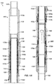
- Fig. 1A illustrates a cross-sectional view of a downhole tool according to the present disclosure.
- Fig. 1B illustrates a detailed view of a portion of the downhole tool.
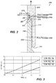
- Fig. 2 illustrates a seal of the disclosed tool in more detail.
- Fig. 3 illustrates a graph of flow passages for the seal of Fig. 2 .
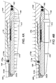
- Figs. 4A-4B show pressure assistance of the seal for the downhole tool when exposed to internal or external pressure differentials.
- Fig. 5 shows the downhole tool in a closed condition.
- Fig. 6 shows the downhole tool in a first condition towards opening.
- Figs. 7-9 show the downhole tool in several subsequent conditions towards opening.
- Figs. 10-14 show the downhole tool being hydraulically actuated in various stages of opening.
- a downhole flow device 100 has a housing 110, a sliding sleeve 120, a ported sleeve 170, a landing 180, and a seal 200.
- the housing (indicated generally by 110) can have a number of interconnecting housing portions 110a-f that facilitate assembly.
- the flow device 100 is a reservoir control tool that couples at uphole and downhole ends 102/104 to other tubing components (not shown), although the teachings of the present disclosure may be used on any other downhole flow device, such as a sliding sleeve, a downhole control valve, a crossover tool, etc.
- the tool 100 operates as a hydraulically-actuated variable choke valve and can adjust the rate of production or injection of fluid through the tool 100.
- the tool 100 can be run as part of a completion tubing string in the well. Once deployed, operators can operate the tool 100 to variably choke back the production from the well's annulus into the tool 100. This may be done to reduce the rate of water produced from the well or to balance the rate of production (and the rate of pressure drop) of one producing zone against another. In some cases, each production zone could have a corresponding tool 100 that can be varied. As opposed to production, the tool 100 may also be used for varied injection of fluids from the tubing string into the annulus of the well.
- the ported sleeve 170 has a plurality of ports 174a-g disposed on an axis of the sleeve 170. Exposure of more or less of the ports 174a-g increases or decreases the flow through the tool 100. Although shown having several separate ports 174a-g, the ported sleeve 170 can have one or more ports disposed along the axis of the sleeve 174 so that more or less exposure of the one or more ports can increase or decrease flow through the tool 100. For example, the ported sleeve 170 can having one port that increases in size along the axis of the ported sleeve 170 and can have any desirable shape.
- the sliding sleeve 120 fits all the way onto the ported sleeve 170 as shown in Figures 1A-1B so that none of the ports 174a-g in the ported sleeve 170 are exposed.
- the seal 200 on the closed sleeves 120/170 seals flow into (or out of) the tool 100 when the sliding sleeve 120 is in a closed position on the ported sleeve 170.
- the tool's sliding sleeve 120 can be hydraulically moved relative to the ported sleeve 170, and the changing position of the sliding sleeve 120 controls the flow into (or out of) the sleeve's bore 172 by disengaging the seal 200 and exposing more or less ports 174 in the ported sleeve 170.
- the seal 200 separates, and the sliding sleeve 120 opens relative to the ports 174 to allow fluid to flow from a surrounding annulus through windows 106 in the tool's housing 110 (i.e., portion 110e) and into the ported sleeve's bore 172 (or vice versa).
- the ports 174a-g defined in the ported sleeve 170 generally increase in size (diameter) along the axis of the sleeve 170.
- the first ports 174a (four of which are defined around the circumference of the ported sleeve 170) have a first diameter, while the other ports 174b-e above them have a slightly greater diameter.
- the next highest port 174f has an even greater diameter, and the last port 174g has the largest diameter.
- the tool 100 can operate at eight discrete positions to control the amount of flow area through the tool 100. These positions are defined in percentages of the flow area of the tubing string (specifically the diameter of the ported sleeve's bore 172). For example, the tool's positions can be defined as follows: 0% closed, 1 % open, 3% open, 5% open, 7% open, 9% open, 15% open, and 100% open. Therefore, with the tool 100 set at the 5% position, the ports 174a-c are exposed, and the flow area through the tool 100 is 5% of the flow area through comparably sized tubing. As will be appreciated, these values are illustrative.
- the actual size and number of ports 174a-g for an implementation depends on the overall size of the tool 100 and the desired or expected flow characteristics as well as other implementation specific details. In other examples, the tool 100 may have more or less ports, and some or all of the ports may have the same diameters.
- the seal 200 has first and second seal components 210/250 that mate with one another when the sliding sleeve 120 is closed.
- the first (moving) component 210 moves with the sliding sleeve 210, while the second (stationary) component 250 remains stationary.
- Either one or both of these components 210/250 can be incorporated into its respective sleeve (as is the stationary component 250) or can be an independent component affixed onto its respective sleeve (as is the movable component 210).
- the seal components 210/250 are intended to reduce damage to the seal 200, and the design of the seal 200 is such that it resists erosion and is self-protecting.
- the moving component 210 has a first inner shelf 212, a first inner ledge 214, a second inner shelf 216, and a second inner ledge 218 ⁇ each of which face inward toward the ported sleeve (not shown).
- the stationary component 250 has a somewhat complimentary configuration, including a first outer shelf 252, a first outer ledge 254, a second outer shelf 256, and a second outer ledge 258 ⁇ each of which face outward from the ported sleeve (not shown).
- the stationary component 250 may also define a well 255 where the second outer shelf 256 mates with the first outer ledge 254.
- the shelves 212/252 define a first flow passage 202
- the first ledges 214/254 define a second flow passage 204
- the second shelves 216/256 define a third flow passage 206 through which fluid can flow through the seal 200.
- the flow passages 202, 204, and 206 create seal points between the metal-to-metal seal produced between the components 210/250. Engagement between the first ledges 214/254 produces the primary sealing function when the components 210/250 are closed against one another.
- seal 200 achieves pressure assisted and erosion resistant sealing on the tool 100.
- the seal 200 is assisted closed in metal-to-metal engagement by either internal pressure acting inside the tool 100 or by external pressure acting outside the tool 100.
- Figures 4A-4B the tool 100 is shown closed, and the seal components 210/250 are shown mated with one another.
- a lower packing element or seal 178 seals between the ported sleeve 170 and the housing 110 (i.e., portion 110f) and isolates fluid pressure inside the tool 100 from outside the tool 100.
- the primary sealing function of the closed seal 200 is provided by engagement of ledges 214/254.
- the engagement 214/254 are set at a circumference that matches a centerline circumference of the lower packing seal 178 on the tool 100.
- the arrangement of the ledges 214/254, centerline, the packing seal 178, and other features give pressure assistance to the seal 200 regardless of whether the tool 100 is exposed to internal or external pressure differentials.
- FIG 4A an internal pressure differential in the bore 112 is shown acting on the tool 100.
- Fluid pressure is capable of acting against the distal end of the ported sleeve 120, which is exposed and unsealed relative to the fluid pressure in the bore 112.
- the fluid pressure can act against the lower shoulder of the packing seal 178.
- This fluid pressure creates a piston effect on the ported sleeve 170.
- the resulting pressure pushes the ported sleeve 170 and its seal component 250 toward the sliding sleeve 120 and its seal component 210, thereby assisting the sealing engagement between them.
- the seal 200 of the present disclosure is intended to control the velocities of abrasive flow and isolates portion of the seal 200 from the flow as much as possible to mitigate erosive damage.
- the first flow passage 202 from the shelves 212/252 creates a very small choke when the components 210/250 are closed or slightly open.
- the second shelves 216/256 providing the second flow passage 206 also provide a secondary choke that reduces the flow possible through the seal components 210/250.
- the first flow passage 202 allows fluid to flow through the seal 200, but the small gap between the shelves 212/252 defines the smallest available flow area through the seal 200.
- This secondary choke from the sealing ledges 214/254 also limits the detrimental flow when the seal components 210/250 are first separated.
- the limited flow area through the first flow passage 202 means that any sudden erosive flow from fluids flowing from the annulus into the tool (or vice versa) mainly interacts with the shelves 212/252. Accordingly, the shelves 212/252 take the brunt of the erosive flow rather than the sealing ledges 214/254 themselves, which are susceptible to detrimental erosion. In this way, the seal 200 can be self-protecting by making erosion occur away from the sealing ledges 214/254 at initial opening of the seal 200.
- the area of the flow through passages 202, 204, 206 changes. Details of how the flow area changes are shown in Figure 3 , which graphs some calculations for a tool 100 having an internal diameter of about 5-in.
- the first flow passage 202 defines a limiting flow area through the tool 100 as the seal 200 is initially opened (i.e., when the sleeve 120 has traveled from 0 to 1-in.).
- the sliding sleeve (120) travels approximately 0.5-in. open from the ported sleeve (170) to expose the first port (174a) and allow 1% of flow through the tool 100.
- the shelves 212/252 act to choke the flow and take the brunt of any erosive flow until the valve is 1 % open.
- the first inner ledge 214 is already moved clear of the first port (174a) so the ledge 214 can avoid erosive flow, as detailed below.
- Figures 5-9 show some initial conditions of the seal 200 as the tool 100 opens (or closes in the reverse).
- the flow area is zero, and the sliding sleeve 120 has not moved.
- the flow passages 202, 206 may allow for some amount of flow, the second flow passage 204 closes off the seal 200 when the ledges 214/254 are engaged.
- the first flow passage 202 from the first shelves 212/252 is extended in comparison to the others so that these shelves 212/252 can define a sacrificial component during initial unloading of pressure.
- the external extension from the first flow passage 202 maintains a tight clearance and creates an orifice effect of any flow therethrough.
- the sealing shelves 212/252 move further apart, the volume and area increases between the two seal components 210/250, thus causing a low pressure area and a drop in flow to develop.
- the choke effect from the shelves 212/252 continues until the moving component 210 has moved until its distal ledge 211 reaches the end of the first outer shelf 252 as shown in Figure 8 . Beyond this position, the seal 200 reaches a second equalizing condition when the distal ledge 211 comes to separate from the ledge 254. When this occurs, the first inner ledge 214 has preferably already passed free of the first ports 174a in the ported sleeve 170. Therefore, erosive damage to the ledge 214 used for closed sealing can be reduced.
- the shelves 212/252 and the distal ledge 211 although they may be subject to more of the erosive flow, are more suited places for such damage to occur. Once the two sealing shelves 212/252 slide far enough apart, the movable component 210 becomes disengaged, allowing full flow into the flow port 172a.
- the tool has eight discrete positions in which the sliding sleeve 120 can reveal ports 174 on the ported sleeve 170 to control flow between 0%, 1%, 3%, 5%, 7%, 9%, 15%, and 100%. Details on how the sliding sleeve 120 is moved relative to the ported sleeve 170 are discussed below.
- the sliding sleeve 120 is moved relative to the ported sleeve 170.
- the sliding sleeve 120 can be moved by any of the techniques conventionally used in the art for a flow device.
- the sliding sleeve 120 can be moved manually using an appropriate pulling tool, hydraulically by a piston arrangement, or other suitable mechanism.
- the disclose tool 100 uses a hydraulically actuated ratcheting motion to move the sliding sleeve 120 relative to the ported sleeve 170. Details of how the tool 100 operates hydraulically are provided in Figures 10-14 .
- FIG 10 portion of the tool 100 is shown in its closed condition so that the sliding sleeve 120 engages the ported sleeve (not shown) with the sealing arrangement as discussed previously.
- two control lines 103a-b connect to hydraulic connections 130 (only one shown) on the tool 100.
- Control fluid in the control lines 103a-b hydraulically move the sliding sleeve 120 relative to the ported sleeve (170).
- These control lines 103a-b run from surface equipment down the tubing string to the tool 100.
- When operators apply pressure to an open control line 103a the tool's sliding sleeve 120 moves from its current position to a next open position (in the order listed previously).
- When operators apply pressure to a close control line 103a the tool's sliding sleeve 120 moves back completely to its closed position.
- pressure from the open control line 130a enters an open port 135 in the housing 110 (i.e., portion 110b) and travels to an outlet at a first chamber 132 between the sliding sleeve 120 and the housing portion 110b.
- the first chamber 132 is formed by upper and lower seals 123a-b between the sliding sleeve 120 and housing portions 110a-b. Fluid pressure fills this first chamber 132 and acts against a shoulder at upper seal 123b to force the sliding sleeve 120 upward in the housing 110 (i.e., the sleeve 120 moves to the left in Fig. 10 ).
- fluid pressure from the open port 135 fills a second chamber 134 at another of the port's outlets. Fluid pressure fills this second chamber 134 and acts against a trigger or unlocking sleeve 140 disposed on the sliding sleeve 120.
- This unlocking sleeve 140 having a shape of a sleeve seals against the housing portions 110b-c with upper and lower seals 143a-b.
- the fluid pressure moves the unlocking sleeve 140 upward in the housing 110 along the sliding sleeve 120 (i.e., to the left in Fig. 10 ). When moved, the unlocking sleeve 140 acts against the bias of a spring 124.
- a catch 150 having dogs 155 is also disposed on the sleeve 120.
- This catch 150 has the shape of a sleeve and has windows for the dogs 155.
- the catch 150 remains in position relative to the housing 110 due to the bias of another spring 126.
- the sliding sleeve 120 moves a certain distance so that the dogs 155 in the catch 150 engage a shoulder of the first slot 125a in the sliding sleeve 120, as shown in Figure 11 .
- the sliding sleeve 120 has opened to its first position (i.e., 1 % open) to expose the first ports (174a) on the ported sleeve (170) (See Fig. 9 ).
- the mechanism is reset. To do this, fluid pressure at the open control line 103a is released.
- the trigger 150 is now freed from upward pressure, and the spring 124 biases the trigger or unlocking sleeve 140 downward (i.e., to the right in Fig. 12 ).
- the end of the unlocking sleeve 140 engages the dogs 155, freeing them from the slot 125a as shown in Figure 13 .
- a pair of C-rings 128a-b help to hold the sliding sleeve 120 when positioned at varying stages along the ported sleeve 170.
- a larger C-ring 128b engages a circumferential groove in the housing portion 110d to hold the sliding sleeve 120 when in the closed position.
- the smaller C-ring 128a engages in a series of smaller circumferential grooves 115 in the housing portion 110d as the sliding sleeve 120 is moved in stages along the ported sleeve 170.
- the unlocking sleeve 140 engaging the dogs 155 and moved by the spring 124 frees the dogs 155 from the slot 125a. This allows the catch 150 to reset. As shown in Figure 14 , the spring 126 pushes the freed catch 150 downward until the dogs 155 engage in the next circumferential slot 125b on the sliding sleeve 120.
- the sliding sleeve 120 can be fully closed on the ported sleeve (170) to stop flow.
- the close control line 103b connects by another port 137 to a chamber.
- the chamber is formed by upper seal 123a between the sliding sleeve 120 and housing portion 110a and by lower seal (123c; Figs. 1A & 9 ) between the sleeve 120 and housing portion 110d.
- the dogs 155 with their angled edges simply ratchet past the various slots 125 along the sleeve 120 as the sleeve 120 can return to its closed position.
- the C-rings 128a-b shown in Figure 1A also ride along the respective grooves 115 in the housing 110 until the larger C-ring 128b engages in the lowest groove when the sleeve 120 has fully closed.
- the tool 100 can then be opened by applying pressure to the open control line 103a according to the previous procedures.
- applying pressure to the close line 103b closes the tool 100 all the way no matter what current position the sliding sleeve 120 has.
- closing at discrete positions may be desired.
- an entire reverse assembly of a catch, trigger, dogs, chambers, and slots can be provided on the tool 100 opposite to those already shown.
- these reverse components can operate in the same manner described above, but only in the reverse direction. In this way, the sliding sleeve 120 can ratchet closed in discrete positions.
- the reverse (downward) components must accommodate the upward movement of the sliding sleeve 120 from the (upward) components (i.e., catch, trigger, dogs, etc. described previously) and vice versa.
Landscapes
- Life Sciences & Earth Sciences (AREA)
- Engineering & Computer Science (AREA)
- Geology (AREA)
- Mining & Mineral Resources (AREA)
- Physics & Mathematics (AREA)
- Environmental & Geological Engineering (AREA)
- Fluid Mechanics (AREA)
- General Life Sciences & Earth Sciences (AREA)
- Geochemistry & Mineralogy (AREA)
- Sliding Valves (AREA)
- Reciprocating Pumps (AREA)
Abstract
Description
- The problem of erosive damage to seals and metal components in downhole flow devices has been a challenge in the industry for quite some time. In a wellbore, for example, sliding sleeves are used in applications where high velocity flow can create a very hostile environment. The high velocity flow, especially when it contains solids, can induce flow erosion even in the hardest materials available. Additionally, when a pressure differential is unloaded across a conventional seal, severe damage can occur that renders the seal inoperable.
- In the prior art, techniques that address unloading of a pressure differential across seals have used thin equalizing slots and diffuser type seals. The arrangement is intended to prevent damage to two sets of seals, or packing units, that create a barrier between the annulus and tubing pressure. Examples of this prior art technique are disclosed in
U.S. Patent Nos. 5,316,084 and5,156,220 . Prior designs such as these may not prevent damage to seals caused by abrasive flow because the seals may never be adequately protected from an initial surge of pressure during the opening sequence. - Although prior art sealing techniques may be effective, operators are continually striving for improvements to reduce the effects of erosion or pressure differential on seals used downhole. Accordingly, the subject matter of the present disclosure is directed to overcoming, or at least reducing the effects of, one or more of the problems set forth above.
- A downhole flow device has a sliding sleeve and a ported sleeve. The sliding sleeve moves hydraulically along an axis of the ported sleeve to reveal successive ports defined along the axis of the ported sleeve. Fluid pressure applied to an open control line enters a sealed chamber between the sliding sleeve and the housing and moves the sliding sleeve along the ported sleeve.
- To limit movement of the sliding sleeve, a catch has a dog that engages in a slot in the sliding sleeve. As the sliding sleeve moves, the dog moves the catch with the sliding sleeve. At a pinnacle position of the catch, the sliding sleeve can no longer be moved by the hydraulic fluid due to the catch engaging a stop. When moving the catch to its stop, the sliding sleeve reveals one of the ports in the ported sleeve, allowing flow to pass through the device.
- To reset the catch so the sliding sleeve can be advanced to reveal the next port, a trigger between the sliding sleeve and housing can also move by the hydraulic pressure applied. This trigger moves on the sliding sleeve until it reaches another stop that limits its movement. When hydraulic pressure is released, the trigger moves by the bias of a spring to a reset position on the sliding sleeve. As it moves, the trigger dislodges the catch's dog from the sleeve's slot. This allows a spring to move the catch to a next lower position where the dog can then engage in a next slot on the sliding sleeve. Once completed, the mechanism is reset so that reapplication of hydraulic pressure can move the sliding sleeve to its next position. Applying hydraulic pressure to another port can move the sliding sleeve all the way back to its closed condition.
- A seal is provided between the sliding sleeve and the ported sleeve. The seal has a first seal component disposed on the sliding sleeve and has a second seal component disposed on the ported sleeve. These seal components engage one another to seal flow, and they move apart to allow fluid flow through the ports in the ported sleeve. Operation of the device and the seal reduce both erosion and damage caused by high velocity flow, abrasive flow, and differential pressures. In other words, the device and seal prevent damage to the seal when unloading a differential pressure across it, and the seal is designed in such a way that abrasive flow does not have the opportunity to impinge on the sealing surface to cause erosion.
- The foregoing summary is not intended to summarize each potential embodiment or every aspect of the present disclosure.
-
Fig. 1A illustrates a cross-sectional view of a downhole tool according to the present disclosure. -
Fig. 1B illustrates a detailed view of a portion of the downhole tool. -
Fig. 2 illustrates a seal of the disclosed tool in more detail. -
Fig. 3 illustrates a graph of flow passages for the seal ofFig. 2 . -
Figs. 4A-4B show pressure assistance of the seal for the downhole tool when exposed to internal or external pressure differentials. -
Fig. 5 shows the downhole tool in a closed condition. -
Fig. 6 shows the downhole tool in a first condition towards opening. -
Figs. 7-9 show the downhole tool in several subsequent conditions towards opening. -
Figs. 10-14 show the downhole tool being hydraulically actuated in various stages of opening. - In
Figures 1A-1B , adownhole flow device 100 has ahousing 110, asliding sleeve 120, a portedsleeve 170, alanding 180, and aseal 200. As shown, the housing (indicated generally by 110) can have a number of interconnectinghousing portions 110a-f that facilitate assembly. In the present implementation, theflow device 100 is a reservoir control tool that couples at uphole and downhole ends 102/104 to other tubing components (not shown), although the teachings of the present disclosure may be used on any other downhole flow device, such as a sliding sleeve, a downhole control valve, a crossover tool, etc. When used for reservoir control, thetool 100 operates as a hydraulically-actuated variable choke valve and can adjust the rate of production or injection of fluid through thetool 100. - For example, the
tool 100 can be run as part of a completion tubing string in the well. Once deployed, operators can operate thetool 100 to variably choke back the production from the well's annulus into thetool 100. This may be done to reduce the rate of water produced from the well or to balance the rate of production (and the rate of pressure drop) of one producing zone against another. In some cases, each production zone could have acorresponding tool 100 that can be varied. As opposed to production, thetool 100 may also be used for varied injection of fluids from the tubing string into the annulus of the well. - The
ported sleeve 170 has a plurality ofports 174a-g disposed on an axis of thesleeve 170. Exposure of more or less of theports 174a-g increases or decreases the flow through thetool 100. Although shown having severalseparate ports 174a-g, theported sleeve 170 can have one or more ports disposed along the axis of thesleeve 174 so that more or less exposure of the one or more ports can increase or decrease flow through thetool 100. For example, the portedsleeve 170 can having one port that increases in size along the axis of theported sleeve 170 and can have any desirable shape. - To choke the flow into or out of the
tool 100 completely, thesliding sleeve 120 fits all the way onto theported sleeve 170 as shown inFigures 1A-1B so that none of theports 174a-g in theported sleeve 170 are exposed. As shown, theseal 200 on the closedsleeves 120/170 seals flow into (or out of) thetool 100 when thesliding sleeve 120 is in a closed position on theported sleeve 170. To achieve variable choking, the tool's slidingsleeve 120 can be hydraulically moved relative to the portedsleeve 170, and the changing position of thesliding sleeve 120 controls the flow into (or out of) the sleeve's bore 172 by disengaging theseal 200 and exposing more orless ports 174 in theported sleeve 170. - When the
sliding sleeve 120 is moved, for example, theseal 200 separates, and thesliding sleeve 120 opens relative to theports 174 to allow fluid to flow from a surrounding annulus throughwindows 106 in the tool's housing 110 (i.e., portion 110e) and into the ported sleeve's bore 172 (or vice versa). As best shown inFigure 1B , theports 174a-g defined in theported sleeve 170 generally increase in size (diameter) along the axis of thesleeve 170. Therefore, thefirst ports 174a (four of which are defined around the circumference of the ported sleeve 170) have a first diameter, while theother ports 174b-e above them have a slightly greater diameter. The next highest port 174f has an even greater diameter, and the last port 174g has the largest diameter. In this way, as the slidingsleeve 120 moves along the portedsleeve 170, the slidingsleeve 120 successively reveals more of theports 174a-g, which increases the flow through thetool 100. - In the current arrangement, the
tool 100 can operate at eight discrete positions to control the amount of flow area through thetool 100. These positions are defined in percentages of the flow area of the tubing string (specifically the diameter of the ported sleeve's bore 172). For example, the tool's positions can be defined as follows: 0% closed, 1 % open, 3% open, 5% open, 7% open, 9% open, 15% open, and 100% open. Therefore, with thetool 100 set at the 5% position, theports 174a-c are exposed, and the flow area through thetool 100 is 5% of the flow area through comparably sized tubing. As will be appreciated, these values are illustrative. The actual size and number ofports 174a-g for an implementation depends on the overall size of thetool 100 and the desired or expected flow characteristics as well as other implementation specific details. In other examples, thetool 100 may have more or less ports, and some or all of the ports may have the same diameters. - As best shown in
Figure 1B , theseal 200 has first andsecond seal components 210/250 that mate with one another when the slidingsleeve 120 is closed. The first (moving)component 210 moves with the slidingsleeve 210, while the second (stationary)component 250 remains stationary. Either one or both of thesecomponents 210/250 can be incorporated into its respective sleeve (as is the stationary component 250) or can be an independent component affixed onto its respective sleeve (as is the movable component 210). As discussed below, theseal components 210/250 are intended to reduce damage to theseal 200, and the design of theseal 200 is such that it resists erosion and is self-protecting. - Details of the
seal 200 are shown inFigure 2 . The movingcomponent 210 has a firstinner shelf 212, a firstinner ledge 214, a secondinner shelf 216, and a secondinner ledge 218―each of which face inward toward the ported sleeve (not shown). Thestationary component 250 has a somewhat complimentary configuration, including a firstouter shelf 252, a firstouter ledge 254, a secondouter shelf 256, and a secondouter ledge 258―each of which face outward from the ported sleeve (not shown). Thestationary component 250 may also define a well 255 where the secondouter shelf 256 mates with the firstouter ledge 254. - The
shelves 212/252 define afirst flow passage 202, thefirst ledges 214/254 define a second flow passage 204, and thesecond shelves 216/256 define athird flow passage 206 through which fluid can flow through theseal 200. Theflow passages components 210/250. Engagement between thefirst ledges 214/254 produces the primary sealing function when thecomponents 210/250 are closed against one another. - With an understanding of the
seal 200 and itscomponents 210/250, discussion now turns to how theseal 200 achieves pressure assisted and erosion resistant sealing on thetool 100. - The
seal 200 is assisted closed in metal-to-metal engagement by either internal pressure acting inside thetool 100 or by external pressure acting outside thetool 100. InFigures 4A-4B , thetool 100 is shown closed, and theseal components 210/250 are shown mated with one another. A lower packing element or seal 178 seals between the portedsleeve 170 and the housing 110 (i.e.,portion 110f) and isolates fluid pressure inside thetool 100 from outside thetool 100. - As noted previously, the primary sealing function of the
closed seal 200 is provided by engagement ofledges 214/254. As constructed, theengagement 214/254 are set at a circumference that matches a centerline circumference of thelower packing seal 178 on thetool 100. As described below, the arrangement of theledges 214/254, centerline, the packingseal 178, and other features give pressure assistance to theseal 200 regardless of whether thetool 100 is exposed to internal or external pressure differentials. - In
Figure 4A , an internal pressure differential in thebore 112 is shown acting on thetool 100. Fluid pressure is capable of acting against the distal end of the portedsleeve 120, which is exposed and unsealed relative to the fluid pressure in thebore 112. As a consequence, the fluid pressure can act against the lower shoulder of the packingseal 178. This fluid pressure creates a piston effect on the portedsleeve 170. The resulting pressure pushes the portedsleeve 170 and itsseal component 250 toward the slidingsleeve 120 and itsseal component 210, thereby assisting the sealing engagement between them. - In
Figure 4B , an external pressure differential is shown acting on thetool 100, but theseal 200 is also pressure assisted in this circumstance. The external fluid pressure acts against the upper shoulder of the packingseal 178. This moves the packingseal 178 away from the ported sleeve's adjacent shoulder so that theseal 178 abuts a landing 180 unconnected to the portedsleeve 170. As a consequence, the fluid pressure can act against the ported sleeve's shoulder. Again, this tends to create a piston effect on the portedsleeve 170 that attempts to push the portedsleeve 170 and itsseal component 250 toward the slidingsleeve 120 and itsseal component 210. Therefore, theseal 200 and configuration of theledges 214/254 and seal 178 help pressure assist the seal produced regardless of whether exposed to an internal or external pressure differential. - As noted previously, the
tool 100 can encounter problems caused by erosive damage to seals and metal components when varying flow therethrough. Theseal 200 of the present disclosure is intended to control the velocities of abrasive flow and isolates portion of theseal 200 from the flow as much as possible to mitigate erosive damage. - Returning to
Figure 2 , thefirst flow passage 202 from theshelves 212/252 creates a very small choke when thecomponents 210/250 are closed or slightly open. Thesecond shelves 216/256 providing thesecond flow passage 206 also provide a secondary choke that reduces the flow possible through theseal components 210/250. - At the instant the
seal components 210/250 start to separate and break the seal between theledges 214/254, thefirst flow passage 202 allows fluid to flow through theseal 200, but the small gap between theshelves 212/252 defines the smallest available flow area through theseal 200. This secondary choke from the sealingledges 214/254 also limits the detrimental flow when theseal components 210/250 are first separated. - The limited flow area through the
first flow passage 202 means that any sudden erosive flow from fluids flowing from the annulus into the tool (or vice versa) mainly interacts with theshelves 212/252. Accordingly, theshelves 212/252 take the brunt of the erosive flow rather than the sealingledges 214/254 themselves, which are susceptible to detrimental erosion. In this way, theseal 200 can be self-protecting by making erosion occur away from the sealingledges 214/254 at initial opening of theseal 200. - As the sliding
sleeve 120 is moved on the portedsleeve 170, the area of the flow throughpassages Figure 3 , which graphs some calculations for atool 100 having an internal diameter of about 5-in. As evident fromFigure 3 , thefirst flow passage 202 defines a limiting flow area through thetool 100 as theseal 200 is initially opened (i.e., when thesleeve 120 has traveled from 0 to 1-in.). - In one implementation, the sliding sleeve (120) travels approximately 0.5-in. open from the ported sleeve (170) to expose the first port (174a) and allow 1% of flow through the
tool 100. In this way, theshelves 212/252 act to choke the flow and take the brunt of any erosive flow until the valve is 1 % open. Even after that point, the firstinner ledge 214 is already moved clear of the first port (174a) so theledge 214 can avoid erosive flow, as detailed below. -
Figures 5-9 show some initial conditions of theseal 200 as thetool 100 opens (or closes in the reverse). In the closed condition shown inFigure 5 , the flow area is zero, and the slidingsleeve 120 has not moved. Although theflow passages 202, 206 (shown inFig. 2 ) may allow for some amount of flow, the second flow passage 204 closes off theseal 200 when theledges 214/254 are engaged. - In a first open condition shown in
Figure 6 , the slidingsleeve 120 is moved upward. The portedsleeve 170 also moved upward because thelanding 180 moves by the bias of thespring 182 and pushes the portedsleeve 170 upward. This keeps theseal 200 closed. Eventually, thepins 176a in the sleeve'sslots 176b limit the travel of thesleeve 170 andlanding 180. - As the sliding
sleeve 120 continues to open, it reaches a first equalizing condition shown inFigure 7 when thesleeve 120 travels from 0.00-in. to about 0.125-in. Theledges 214/254 move apart. The length and diametric gap of theledges 214/254 provides for an orifice effect of any flow through theseal 200. This helps to protect the metal seal surfaces during initial unloading of pressure and flow as described previously. The timing of this orifice effect is minimal as it is needed only during the first movement of separation of the twoseal components 210/250. However, the flow passage 202 (See also,Fig. 2 ) from theshelves 212/252 act to choke the flow, thereby limiting the actual flow that travels through theseal 200. - The
first flow passage 202 from thefirst shelves 212/252 is extended in comparison to the others so that theseshelves 212/252 can define a sacrificial component during initial unloading of pressure. As the two sealingcomponents 210/250 continue to separate, the external extension from thefirst flow passage 202 maintains a tight clearance and creates an orifice effect of any flow therethrough. As the sealingshelves 212/252 move further apart, the volume and area increases between the twoseal components 210/250, thus causing a low pressure area and a drop in flow to develop. - The choke effect from the
shelves 212/252 continues until the movingcomponent 210 has moved until itsdistal ledge 211 reaches the end of the firstouter shelf 252 as shown inFigure 8 . Beyond this position, theseal 200 reaches a second equalizing condition when thedistal ledge 211 comes to separate from theledge 254. When this occurs, the firstinner ledge 214 has preferably already passed free of thefirst ports 174a in the portedsleeve 170. Therefore, erosive damage to theledge 214 used for closed sealing can be reduced. Theshelves 212/252 and thedistal ledge 211, although they may be subject to more of the erosive flow, are more suited places for such damage to occur. Once the two sealingshelves 212/252 slide far enough apart, themovable component 210 becomes disengaged, allowing full flow into the flow port 172a. - At a subsequent opened conditions after
Figure 8 , the flow through theseal 200 increases asflow ports 174a are further revealed. Finally, at the opened condition shown inFigure 9 when the slidingsleeve 120 has traveled to about 2.00-in., the flow area through theports 174a is 1% of the flow possible through the diameter of the portedsleeve 170. - With further movement of the sliding
sleeve 120, more of theports 174 in the portedsleeve 170 can be revealed. Again, as note previously, the tool has eight discrete positions in which the slidingsleeve 120 can revealports 174 on the portedsleeve 170 to control flow between 0%, 1%, 3%, 5%, 7%, 9%, 15%, and 100%. Details on how the slidingsleeve 120 is moved relative to the portedsleeve 170 are discussed below. - As noted previously, the sliding
sleeve 120 is moved relative to the portedsleeve 170. In general, the slidingsleeve 120 can be moved by any of the techniques conventionally used in the art for a flow device. For example, the slidingsleeve 120 can be moved manually using an appropriate pulling tool, hydraulically by a piston arrangement, or other suitable mechanism. In the current implementation, thedisclose tool 100 uses a hydraulically actuated ratcheting motion to move the slidingsleeve 120 relative to the portedsleeve 170. Details of how thetool 100 operates hydraulically are provided inFigures 10-14 . - In
Figure 10 , portion of thetool 100 is shown in its closed condition so that the slidingsleeve 120 engages the ported sleeve (not shown) with the sealing arrangement as discussed previously. As shown inFigure 10 , twocontrol lines 103a-b connect to hydraulic connections 130 (only one shown) on thetool 100. Control fluid in thecontrol lines 103a-b hydraulically move the slidingsleeve 120 relative to the ported sleeve (170). Thesecontrol lines 103a-b run from surface equipment down the tubing string to thetool 100. When operators apply pressure to anopen control line 103a, the tool's slidingsleeve 120 moves from its current position to a next open position (in the order listed previously). When operators apply pressure to aclose control line 103a, the tool's slidingsleeve 120 moves back completely to its closed position. - In the opening procedure, for example, pressure from the open control line 130a enters an
open port 135 in the housing 110 (i.e.,portion 110b) and travels to an outlet at afirst chamber 132 between the slidingsleeve 120 and thehousing portion 110b. Thefirst chamber 132 is formed by upper andlower seals 123a-b between the slidingsleeve 120 andhousing portions 110a-b. Fluid pressure fills thisfirst chamber 132 and acts against a shoulder atupper seal 123b to force the slidingsleeve 120 upward in the housing 110 (i.e., thesleeve 120 moves to the left inFig. 10 ). - At the same time, fluid pressure from the
open port 135 fills asecond chamber 134 at another of the port's outlets. Fluid pressure fills thissecond chamber 134 and acts against a trigger or unlockingsleeve 140 disposed on the slidingsleeve 120. This unlockingsleeve 140 having a shape of a sleeve seals against thehousing portions 110b-c with upper andlower seals 143a-b. The fluid pressure moves the unlockingsleeve 140 upward in thehousing 110 along the sliding sleeve 120 (i.e., to the left inFig. 10 ). When moved, the unlockingsleeve 140 acts against the bias of aspring 124. - The results of this movement are shown in
Figure 11 . As the open control line 130a supplies fluid pressure to thechambers sleeve 120 moves a first extent inside thehousing 110, and the unlockingsleeve 140 also moves along with the slidingsleeve 120 against the bias of thespring 124. - A
catch 150 havingdogs 155 is also disposed on thesleeve 120. Thiscatch 150 has the shape of a sleeve and has windows for thedogs 155. As the fluid pressure moves the slidingsleeve 120, thecatch 150 remains in position relative to thehousing 110 due to the bias of anotherspring 126. Eventually, the slidingsleeve 120 moves a certain distance so that thedogs 155 in thecatch 150 engage a shoulder of thefirst slot 125a in the slidingsleeve 120, as shown inFigure 11 . - Continued pressure at the
open control lines 103a moves thesleeve 120 further in thehousing 110. Thecatch 150 engaged bydogs 155 in thefirst groove 125a also moves upward as shown inFigure 12 . Once thecatch 150 reaches its topmost stroke, it engages aninternal shoulder 138 in thehousing portion 110c. This prevents further movement upward of the slidingsleeve 120. - At this point, the sliding
sleeve 120 has opened to its first position (i.e., 1 % open) to expose the first ports (174a) on the ported sleeve (170) (SeeFig. 9 ). To be able to open further, the mechanism is reset. To do this, fluid pressure at theopen control line 103a is released. Thetrigger 150 is now freed from upward pressure, and thespring 124 biases the trigger or unlockingsleeve 140 downward (i.e., to the right inFig. 12 ). The end of the unlockingsleeve 140 engages thedogs 155, freeing them from theslot 125a as shown inFigure 13 . - Although fluid pressure at the open control line 130a is released, the sliding
sleeve 120 does not move back downward in thehousing 110. As noted previously and as shown inFigure 1A , a pair of C-rings 128a-b help to hold the slidingsleeve 120 when positioned at varying stages along the portedsleeve 170. A larger C-ring 128b engages a circumferential groove in thehousing portion 110d to hold the slidingsleeve 120 when in the closed position. The smaller C-ring 128a engages in a series of smallercircumferential grooves 115 in thehousing portion 110d as the slidingsleeve 120 is moved in stages along the portedsleeve 170. - Returning to
Figure 13 , the unlockingsleeve 140 engaging thedogs 155 and moved by thespring 124 frees thedogs 155 from theslot 125a. This allows thecatch 150 to reset. As shown inFigure 14 , thespring 126 pushes the freedcatch 150 downward until thedogs 155 engage in the nextcircumferential slot 125b on the slidingsleeve 120. - Further opening of the sliding
sleeve 120 can then be achieved through the same process outlined above. Pressure can again be applied to theopen control line 103a, and the slidingsleeve 120 can be ratcheted upward in the housing to the next slotted position by the repeated actions. Release of pressure at theopen control line 103a can then reset the hydraulic components for the next movement. Operated in this manner, thetool 100 can be set to any open condition to vary and control the flow from 1% to 100% at the discrete positions in the present example. - In any of the open conditions, the sliding
sleeve 120 can be fully closed on the ported sleeve (170) to stop flow. As best shown inFigure 14 , theclose control line 103b connects by anotherport 137 to a chamber. In this case, the chamber is formed byupper seal 123a between the slidingsleeve 120 andhousing portion 110a and by lower seal (123c;Figs. 1A &9 ) between thesleeve 120 andhousing portion 110d. When operators apply pressure to theclose control line 103b at any time, the tool'ssleeve 120 moves back to its fully closed position, which isolates the tubing from the annulus and stops flow through thetool 100. In thecatch 150, thedogs 155 with their angled edges simply ratchet past thevarious slots 125 along thesleeve 120 as thesleeve 120 can return to its closed position. Likewise, the C-rings 128a-b shown inFigure 1A also ride along therespective grooves 115 in thehousing 110 until the larger C-ring 128b engages in the lowest groove when thesleeve 120 has fully closed. Thetool 100 can then be opened by applying pressure to theopen control line 103a according to the previous procedures. - In the current implementation, applying pressure to the
close line 103b closes thetool 100 all the way no matter what current position the slidingsleeve 120 has. In some implementations, closing at discrete positions may be desired. To do this, an entire reverse assembly of a catch, trigger, dogs, chambers, and slots can be provided on thetool 100 opposite to those already shown. When hydraulic pressure is applied to theclose line 103b, these reverse components can operate in the same manner described above, but only in the reverse direction. In this way, the slidingsleeve 120 can ratchet closed in discrete positions. To operate, the reverse (downward) components must accommodate the upward movement of the slidingsleeve 120 from the (upward) components (i.e., catch, trigger, dogs, etc. described previously) and vice versa. - The foregoing description of preferred and other embodiments is not intended to limit or restrict the scope or applicability of the inventive concepts conceived of by the Applicants. In exchange for disclosing the inventive concepts contained herein, the Applicants desire all patent rights afforded by the appended claims. Therefore, it is intended that the appended claims include all modifications and alterations to the full extent that they come within the scope of the following claims or the equivalents thereof.
Claims (19)
- A downhole flow device, comprising:a housing having a landing disposed therein;a first sleeve disposed in the housing and having an end abutting the landing, the first sleeve having a first internal bore and defining one or more ports on an axis thereof;a first seal component disposed on the first sleeve adjacent the one or more ports;a packing seal disposed between the first sleeve and the housing;a second sleeve having a second internal bore disposed on the first sleeve, the second sleeve movable along the axis relative to the one or more ports; anda second seal component disposed on the second sleeve and engageable with the first seal component,wherein the packing seal assists engagement between the first and second components in response to a pressure differential acting against the first or second sleeves.
- The device of claim 1, further comprising a biasing member biasing the landing to abut the end of the first sleeve, wherein the first sleeve is movable in the housing.
- The device of claim 2, wherein the first sleeve defines a slot, and wherein the housing comprises a pin disposed in the slot, the pin limiting movement of the first sleeve between first and second positions in the housing.
- The device of claim 1, wherein the first sleeve defines a first shoulder facing away from the first seal component, wherein the landing defines a second shoulder facing toward the first shoulder, the first and second shoulders forming an annular space around the first sleeve, the packing seal having first and second ends and movably disposed in the annular space.
- The device of claim 1 or 4, wherein the packing seal assists engagement of the second seal component with the first seal component in response to an internal pressure differential acting inside the first internal bore of the first sleeve.
- The device of claim 5, wherein the internal pressure acts against the second end of the packing seal and moves the first end of the packing seal against the first shoulder of the first sleeve.
- The device of claim 1 or 4, wherein the packing seal assists engagement of the second seal component with the first seal component in response to an external pressure differential acting outside the first sleeve.
- The device of claim 7, wherein the external pressure acts against the first end of the packing seal and moves the second end of the packing seal against the second shoulder of the landing; and wherein the external pressure acts against the first shoulder of the first sleeve.
- The device of claim 1, wherein:the first seal component comprises a first shelf facing outward and a first ledge extending inward from the first shelf;the second seal component comprises a second shelf facing inward and a second ledge extending outward from the second shelf; andthe first inside and outside shelves define a first minimum flow passage through the seal when the seal is moved between a closed condition and a first opened condition.
- The device of claim 9, wherein the first and second ledges engage one another when the first and second seal components are moved to the closed condition; and wherein the first ledge passes a first of the one or more ports along the axis when distal ends of the first and second shelves meet in the first opened condition.
- The device of claim 9, wherein a centerline of the packing seal aligns with third shelves extending from the first and second ledges.
- The device of claim 11, wherein the third shelves define a second minimum flow passage through the first and second seal components when moved to an intermediate condition between the closed condition and the first opened condition.
- The device of claim 1, further comprising a mechanism moving the second sleeve along the axis of the first sleeve in response to hydraulic pressure.
- The device of claim 13, wherein the mechanism comprises:a first piston moving the second sleeve in a first direction in response to first hydraulic pressure,a second piston moving a trigger disposed on the second sleeve in the first direction in response to the first hydraulic pressure, anda catch having a dog engaging in a first slot in the second sleeve and moving in the first direction with the second sleeve.
- The device of claim 14, wherein the mechanism comprises a first hydraulic port communicating the first hydraulic pressure to the first and second pistons.
- The device of claim 14, wherein the catch moves to a stop preventing movement of the second sleeve in the first direction, and wherein the trigger moves to a stop preventing movement of the trigger.
- The device of claim 14, wherein in the absence of the first hydraulic pressure, the trigger moves in a second direction opposite to the first direction and disengages the dog from the first slot, and wherein the catch moves in the second direction until the dog engages in a second slot defined in the second sleeve.
- The device of claim 14, wherein a first biasing member biases the trigger in the second direction, and wherein a second biasing member biases the catch in the second direction.
- The device of claim 14, wherein the mechanism moves the second sleeve along the axis of the first sleeve in a second direction opposite the first direction in response to second hydraulic pressure.
Applications Claiming Priority (1)
| Application Number | Priority Date | Filing Date | Title |
|---|---|---|---|
| US12/912,295 US8657010B2 (en) | 2010-10-26 | 2010-10-26 | Downhole flow device with erosion resistant and pressure assisted metal seal |
Publications (3)
| Publication Number | Publication Date |
|---|---|
| EP2447466A2 true EP2447466A2 (en) | 2012-05-02 |
| EP2447466A3 EP2447466A3 (en) | 2017-03-15 |
| EP2447466B1 EP2447466B1 (en) | 2018-10-31 |
Family
ID=43567648
Family Applications (1)
| Application Number | Title | Priority Date | Filing Date |
|---|---|---|---|
| EP10192151.8A Not-in-force EP2447466B1 (en) | 2010-10-26 | 2010-11-23 | Downhole flow device with erosion resistant and pressure assisted metal seal |
Country Status (4)
| Country | Link |
|---|---|
| US (1) | US8657010B2 (en) |
| EP (1) | EP2447466B1 (en) |
| AU (1) | AU2010243081B2 (en) |
| CA (1) | CA2721545C (en) |
Cited By (17)
| Publication number | Priority date | Publication date | Assignee | Title |
|---|---|---|---|---|
| WO2014178723A1 (en) | 2013-04-29 | 2014-11-06 | Typhonix As | Flow and fluid conditioning pressure reducing valve or device |
| WO2019226353A1 (en) * | 2018-05-22 | 2019-11-28 | Halliburton Energy Services, Inc. | Remote-open device for well operation |
| US11187059B2 (en) | 2015-05-01 | 2021-11-30 | Churchill Drilling Tools Limited | Downhole sealing |
| US12258828B2 (en) | 2022-06-15 | 2025-03-25 | Halliburton Energy Services, Inc. | Sealing/anchoring tool employing a hydraulically deformable member and an expandable metal circlet |
| US12258723B2 (en) | 2021-06-01 | 2025-03-25 | Halliburton Energy Services, Inc. | Expanding metal used in forming support structures |
| US12326060B2 (en) | 2021-05-21 | 2025-06-10 | Halliburton Energy Services, Inc. | Wellbore anchor including one or more activation chambers |
| US12338705B2 (en) | 2020-08-13 | 2025-06-24 | Halliburton Energy Services, Inc. | Expandable metal displacement plug |
| US12345119B2 (en) | 2021-05-28 | 2025-07-01 | Halliburton Energy Services, Inc. | Rapid setting expandable metal |
| US12345115B2 (en) | 2020-01-17 | 2025-07-01 | Halliburton Energy Services, Inc. | Heaters to accelerate setting of expandable metal |
| US12345116B2 (en) | 2021-04-12 | 2025-07-01 | Halliburton Energy Services, Inc. | Expandable metal as backup for elastomeric elements |
| US12345117B2 (en) | 2021-05-28 | 2025-07-01 | Halliburton Energy Services, Inc. | Individual separate chunks of expandable metal |
| US12352127B2 (en) | 2020-01-17 | 2025-07-08 | Halliburton Energy Services, Inc. | Voltage to accelerate/decelerate expandable metal |
| US12378832B2 (en) | 2021-10-05 | 2025-08-05 | Halliburton Energy Services, Inc. | Expandable metal sealing/anchoring tool |
| US12385340B2 (en) | 2022-12-05 | 2025-08-12 | Halliburton Energy Services, Inc. | Reduced backlash sealing/anchoring assembly |
| US12421824B2 (en) | 2021-05-29 | 2025-09-23 | Halliburton Energy Services, Inc. | Using expandable metal as an alternate to existing metal to metal seals |
| US12516577B2 (en) | 2020-02-28 | 2026-01-06 | Halliburton Energy Services, Inc. | Textured surfaces of expanding metal for centralizer, mixing, and differential sticking |
| US12553307B2 (en) | 2019-08-06 | 2026-02-17 | Halliburton Energy Services, Inc. | Expandable metal gas lift mandrel plug |
Families Citing this family (9)
| Publication number | Priority date | Publication date | Assignee | Title |
|---|---|---|---|---|
| US9488039B2 (en) * | 2014-07-03 | 2016-11-08 | Baker Hughes Incorporated | Multi-zone single treatment gravel pack system |
| CN104847301B (en) * | 2015-04-28 | 2017-12-05 | 中国石油天然气股份有限公司 | Open hole packer |
| GB2557103B (en) * | 2015-09-29 | 2021-07-14 | Halliburton Energy Services Inc | Erosion protection for closing sleeve assemblies |
| BR112018003712B1 (en) * | 2015-09-29 | 2022-11-01 | Halliburton Energy Services, Inc | CLOSING GLOVE SET, CLOSING GLOVE, AND, WELL SYSTEM |
| US20180328496A1 (en) * | 2017-05-10 | 2018-11-15 | Baker Hughes Incorporated | Flow diffuser valve and system |
| US10502023B2 (en) * | 2017-10-12 | 2019-12-10 | Baker Hughes, A Ge Company, Llc | Valve arrangement, system and method |
| NO20230134A1 (en) | 2020-12-30 | 2023-02-09 | Halliburton Energy Services Inc | Interval control valve including an expanding metal sealed and anchored joints |
| GB2612511B (en) | 2020-12-30 | 2025-06-18 | Halliburton Energy Services Inc | Multilateral junction having expanding metal sealed and anchored joints |
| US12516589B2 (en) | 2023-09-21 | 2026-01-06 | Halliburton Energy Services, Inc. | Downhole flow control valve for well systems |
Citations (1)
| Publication number | Priority date | Publication date | Assignee | Title |
|---|---|---|---|---|
| US5156220A (en) | 1990-08-27 | 1992-10-20 | Baker Hughes Incorporated | Well tool with sealing means |
Family Cites Families (69)
| Publication number | Priority date | Publication date | Assignee | Title |
|---|---|---|---|---|
| US2317021A (en) | 1940-02-05 | 1943-04-20 | Bassinger Ross | By-pass and releasing means |
| US2853265A (en) | 1955-08-12 | 1958-09-23 | Baker Oil Tools Inc | Telescopic valve apparatus for testing well bore tubing |
| US2888080A (en) | 1957-12-13 | 1959-05-26 | Jersey Prod Res Co | Permanent well completion apparatus |
| US3051243A (en) | 1958-12-12 | 1962-08-28 | George G Grimmer | Well tools |
| US3071193A (en) | 1960-06-02 | 1963-01-01 | Camco Inc | Well tubing sliding sleeve valve |
| US3151681A (en) | 1960-08-08 | 1964-10-06 | Cicero C Brown | Sleeve valve for well pipes |
| US3395758A (en) | 1964-05-27 | 1968-08-06 | Otis Eng Co | Lateral flow duct and flow control device for wells |
| US3355142A (en) | 1964-09-29 | 1967-11-28 | Baker Oil Tools Inc | Sleeve or piston type valve device |
| US3414060A (en) | 1967-11-20 | 1968-12-03 | Joseph T. Zak | Selective shifting tool |
| US3773441A (en) | 1971-05-19 | 1973-11-20 | A Schertz | Combination sand bailer and fluid pump with automatic grit separator and lubricator |
| US4134454A (en) * | 1977-09-21 | 1979-01-16 | Otis Engineering Corporation | Multi-stage sliding valve fluid operated and pressure balanced |
| US4270610A (en) * | 1980-01-15 | 1981-06-02 | Halliburton Company | Annulus pressure operated closure valve with improved power mandrel |
| US4532987A (en) | 1984-02-21 | 1985-08-06 | Reed Lehman T | Geothermal expansion spool piston |
| US4633952A (en) * | 1984-04-03 | 1987-01-06 | Halliburton Company | Multi-mode testing tool and method of use |
| US4971099A (en) | 1989-12-15 | 1990-11-20 | Cooper Industries, Inc. | Pressure balanced cartridge choke valve |
| US5263683A (en) | 1992-05-05 | 1993-11-23 | Grace Energy Corporation | Sliding sleeve valve |
| US5299640A (en) | 1992-10-19 | 1994-04-05 | Halliburton Company | Knife gate valve stage cementer |
| US5364110A (en) | 1992-12-11 | 1994-11-15 | Halliburton Company | Downhole tool metal-to-metal seal |
| US5611547A (en) | 1993-11-04 | 1997-03-18 | Baker Hughes Incorporated | Elongated seal assembly for sealing well tubing-to liner annulus |
| US5443129A (en) | 1994-07-22 | 1995-08-22 | Smith International, Inc. | Apparatus and method for orienting and setting a hydraulically-actuatable tool in a borehole |
| US5718289A (en) | 1996-03-05 | 1998-02-17 | Halliburton Energy Services, Inc. | Apparatus and method for use in injecting fluids in a well |
| CA2221152C (en) | 1996-04-01 | 2004-03-16 | Baker Hughes Incorporated | Downhole flow control devices |
| US6237683B1 (en) | 1996-04-26 | 2001-05-29 | Camco International Inc. | Wellbore flow control device |
| US5896928A (en) | 1996-07-01 | 1999-04-27 | Baker Hughes Incorporated | Flow restriction device for use in producing wells |
| US6041857A (en) | 1997-02-14 | 2000-03-28 | Baker Hughes Incorporated | Motor drive actuator for downhole flow control devices |
| US6070670A (en) | 1997-05-01 | 2000-06-06 | Weatherford/Lamb, Inc. | Movement control system for wellbore apparatus and method of controlling a wellbore tool |
| US6112816A (en) | 1997-07-10 | 2000-09-05 | Camco International Inc. | Single-phase annulus-operated sliding sleeve |
| US5979558A (en) | 1997-07-21 | 1999-11-09 | Bouldin; Brett Wayne | Variable choke for use in a subterranean well |
| US5957208A (en) | 1997-07-21 | 1999-09-28 | Halliburton Energy Services, Inc. | Flow control apparatus |
| US5957207A (en) | 1997-07-21 | 1999-09-28 | Halliburton Energy Services, Inc. | Flow control apparatus for use in a subterranean well and associated methods |
| US6044908A (en) | 1998-05-29 | 2000-04-04 | Grant Prideco, Inc. | Sliding sleeve valve and seal ring for use therein |
| NO306033B1 (en) | 1998-06-05 | 1999-09-06 | Ziebel As | Device and method for independently controlling control devices for regulating fluid flow between a hydrocarbon reservoir and a well |
| GB2340156B (en) | 1998-07-29 | 2003-01-08 | Schlumberger Holdings | Retainer valve |
| GB2344364B (en) * | 1998-11-20 | 2003-07-09 | Klaas Johannes Zwart | Flow control device |
| US6276458B1 (en) | 1999-02-01 | 2001-08-21 | Schlumberger Technology Corporation | Apparatus and method for controlling fluid flow |
| US6328112B1 (en) | 1999-02-01 | 2001-12-11 | Schlumberger Technology Corp | Valves for use in wells |
| US6253850B1 (en) | 1999-02-24 | 2001-07-03 | Shell Oil Company | Selective zonal isolation within a slotted liner |
| US6434651B1 (en) | 1999-03-01 | 2002-08-13 | Sun Microsystems, Inc. | Method and apparatus for suppressing interrupts in a high-speed network environment |
| US6338385B1 (en) | 1999-04-16 | 2002-01-15 | Hydril Company | Retrievable downhole adjustable choke |
| US6328729B1 (en) | 1999-04-27 | 2001-12-11 | General Surgical Innovations, Inc. | Colporrhaphy method and apparatus |
| US6227302B1 (en) | 1999-06-03 | 2001-05-08 | Cameo International, Inc. | Apparatus and method for controlling fluid flow in a wellbore |
| US6189619B1 (en) | 1999-06-07 | 2001-02-20 | Mark L. Wyatt | Sliding sleeve assembly for subsurface flow control |
| US6371208B1 (en) | 1999-06-24 | 2002-04-16 | Baker Hughes Incorporated | Variable downhole choke |
| US6513599B1 (en) | 1999-08-09 | 2003-02-04 | Schlumberger Technology Corporation | Thru-tubing sand control method and apparatus |
| US6668935B1 (en) | 1999-09-24 | 2003-12-30 | Schlumberger Technology Corporation | Valve for use in wells |
| US6446729B1 (en) | 1999-10-18 | 2002-09-10 | Schlumberger Technology Corporation | Sand control method and apparatus |
| EP1484198A3 (en) | 1999-12-22 | 2005-12-07 | Sumitomo Rubber Industries Limited | Noise damper for a pneumatic tyre |
| US6318729B1 (en) | 2000-01-21 | 2001-11-20 | Greene, Tweed Of Delaware, Inc. | Seal assembly with thermal expansion restricter |
| NO309955B1 (en) | 2000-04-28 | 2001-04-23 | Ziebel As | Device by a sleeve valve and method for assembling the same |
| GB2399845B (en) | 2000-08-17 | 2005-01-12 | Abb Offshore Systems Ltd | Flow control device |
| US6422317B1 (en) | 2000-09-05 | 2002-07-23 | Halliburton Energy Services, Inc. | Flow control apparatus and method for use of the same |
| NO313341B1 (en) | 2000-12-04 | 2002-09-16 | Ziebel As | Sleeve valve for regulating fluid flow and method for assembling a sleeve valve |
| NO20006170A (en) | 2000-12-04 | 2002-03-11 | Triangle Equipment As | Device for opening in an outer sleeve which is part of a sleeve valve and method for assembling a sleeve valve |
| CA2376806C (en) | 2001-03-14 | 2008-02-12 | Schlumberger Canada Limited | Tool string |
| US6575243B2 (en) | 2001-04-16 | 2003-06-10 | Schlumberger Technology Corporation | Zonal isolation tool with same trip pressure test |
| US6763892B2 (en) | 2001-09-24 | 2004-07-20 | Frank Kaszuba | Sliding sleeve valve and method for assembly |
| US6715558B2 (en) | 2002-02-25 | 2004-04-06 | Halliburton Energy Services, Inc. | Infinitely variable control valve apparatus and method |
| US6722439B2 (en) | 2002-03-26 | 2004-04-20 | Baker Hughes Incorporated | Multi-positioned sliding sleeve valve |
| US6860330B2 (en) | 2002-12-17 | 2005-03-01 | Weatherford/Lamb Inc. | Choke valve assembly for downhole flow control |
| US20040129431A1 (en) | 2003-01-02 | 2004-07-08 | Stephen Jackson | Multi-pressure regulating valve system for expander |
| US7363981B2 (en) | 2003-12-30 | 2008-04-29 | Weatherford/Lamb, Inc. | Seal stack for sliding sleeve |
| US7367393B2 (en) | 2004-06-01 | 2008-05-06 | Baker Hughes Incorporated | Pressure monitoring of control lines for tool position feedback |
| GB0509800D0 (en) | 2005-05-13 | 2005-06-22 | Petrowell Ltd | Apparatus |
| US7258323B2 (en) | 2005-06-15 | 2007-08-21 | Schlumberger Technology Corporation | Variable radial flow rate control system |
| US7377327B2 (en) | 2005-07-14 | 2008-05-27 | Weatherford/Lamb, Inc. | Variable choke valve |
| US9033054B2 (en) | 2006-08-03 | 2015-05-19 | Welldynamics, Inc. | Metal to metal seal for downhole tools |
| US7823633B2 (en) * | 2007-10-09 | 2010-11-02 | Mark David Hartwell | Valve apparatus |
| US8186439B2 (en) | 2007-12-19 | 2012-05-29 | Baker Hughes Incorporated | Controller for a hydraulically operated downhole tool |
| GB0822144D0 (en) * | 2008-12-04 | 2009-01-14 | Petrowell Ltd | Flow control device |
-
2010
- 2010-10-26 US US12/912,295 patent/US8657010B2/en not_active Expired - Fee Related
- 2010-11-18 CA CA2721545A patent/CA2721545C/en not_active Expired - Fee Related
- 2010-11-18 AU AU2010243081A patent/AU2010243081B2/en not_active Ceased
- 2010-11-23 EP EP10192151.8A patent/EP2447466B1/en not_active Not-in-force
Patent Citations (2)
| Publication number | Priority date | Publication date | Assignee | Title |
|---|---|---|---|---|
| US5156220A (en) | 1990-08-27 | 1992-10-20 | Baker Hughes Incorporated | Well tool with sealing means |
| US5316084A (en) | 1990-08-27 | 1994-05-31 | Baker Hughes Incorporated | Well tool with sealing means |
Cited By (25)
| Publication number | Priority date | Publication date | Assignee | Title |
|---|---|---|---|---|
| WO2014178723A1 (en) | 2013-04-29 | 2014-11-06 | Typhonix As | Flow and fluid conditioning pressure reducing valve or device |
| US9650862B2 (en) | 2013-04-29 | 2017-05-16 | Typhonix As | Flow and fluid conditioning pressure reducing valve or device |
| US10053956B2 (en) | 2013-04-29 | 2018-08-21 | Typhonix As | Flow and fluid conditioning pressure reducing valve or device |
| US11187059B2 (en) | 2015-05-01 | 2021-11-30 | Churchill Drilling Tools Limited | Downhole sealing |
| US11802462B2 (en) | 2015-05-01 | 2023-10-31 | Churchill Drilling Tools Limited | Downhole sealing |
| WO2019226353A1 (en) * | 2018-05-22 | 2019-11-28 | Halliburton Energy Services, Inc. | Remote-open device for well operation |
| GB2585297A (en) * | 2018-05-22 | 2021-01-06 | Halliburton Energy Services Inc | Remote-open device for well operation |
| US11286749B2 (en) | 2018-05-22 | 2022-03-29 | Halliburton Energy Services, Inc. | Remote-open device for well operation |
| GB2585297B (en) * | 2018-05-22 | 2022-09-07 | Halliburton Energy Services Inc | Remote-open device for well operation |
| US12553307B2 (en) | 2019-08-06 | 2026-02-17 | Halliburton Energy Services, Inc. | Expandable metal gas lift mandrel plug |
| US12352127B2 (en) | 2020-01-17 | 2025-07-08 | Halliburton Energy Services, Inc. | Voltage to accelerate/decelerate expandable metal |
| US12345115B2 (en) | 2020-01-17 | 2025-07-01 | Halliburton Energy Services, Inc. | Heaters to accelerate setting of expandable metal |
| US12516577B2 (en) | 2020-02-28 | 2026-01-06 | Halliburton Energy Services, Inc. | Textured surfaces of expanding metal for centralizer, mixing, and differential sticking |
| US12421823B2 (en) | 2020-08-13 | 2025-09-23 | Halliburton Energy Services, Inc. | Valve including an expandable metal seal |
| US12338705B2 (en) | 2020-08-13 | 2025-06-24 | Halliburton Energy Services, Inc. | Expandable metal displacement plug |
| US12345116B2 (en) | 2021-04-12 | 2025-07-01 | Halliburton Energy Services, Inc. | Expandable metal as backup for elastomeric elements |
| US12326060B2 (en) | 2021-05-21 | 2025-06-10 | Halliburton Energy Services, Inc. | Wellbore anchor including one or more activation chambers |
| US12345117B2 (en) | 2021-05-28 | 2025-07-01 | Halliburton Energy Services, Inc. | Individual separate chunks of expandable metal |
| US12345119B2 (en) | 2021-05-28 | 2025-07-01 | Halliburton Energy Services, Inc. | Rapid setting expandable metal |
| US12421824B2 (en) | 2021-05-29 | 2025-09-23 | Halliburton Energy Services, Inc. | Using expandable metal as an alternate to existing metal to metal seals |
| US12258723B2 (en) | 2021-06-01 | 2025-03-25 | Halliburton Energy Services, Inc. | Expanding metal used in forming support structures |
| US12378832B2 (en) | 2021-10-05 | 2025-08-05 | Halliburton Energy Services, Inc. | Expandable metal sealing/anchoring tool |
| US12305459B2 (en) | 2022-06-15 | 2025-05-20 | Halliburton Energy Services, Inc. | Sealing/anchoring tool employing an expandable metal circlet |
| US12258828B2 (en) | 2022-06-15 | 2025-03-25 | Halliburton Energy Services, Inc. | Sealing/anchoring tool employing a hydraulically deformable member and an expandable metal circlet |
| US12385340B2 (en) | 2022-12-05 | 2025-08-12 | Halliburton Energy Services, Inc. | Reduced backlash sealing/anchoring assembly |
Also Published As
| Publication number | Publication date |
|---|---|
| CA2721545C (en) | 2015-12-29 |
| EP2447466A3 (en) | 2017-03-15 |
| US8657010B2 (en) | 2014-02-25 |
| EP2447466B1 (en) | 2018-10-31 |
| AU2010243081B2 (en) | 2013-03-21 |
| AU2010243081A1 (en) | 2012-05-10 |
| CA2721545A1 (en) | 2012-04-26 |
| US20120097386A1 (en) | 2012-04-26 |
Similar Documents
| Publication | Publication Date | Title |
|---|---|---|
| EP2447466B1 (en) | Downhole flow device with erosion resistant and pressure assisted metal seal | |
| US7575058B2 (en) | Incremental annular choke | |
| US20190136665A1 (en) | Downhole sub with hydraulically actuable sleeve valve | |
| US9255466B2 (en) | Liner hanger fluid diverter tool and related methods | |
| US7556102B2 (en) | High differential shifting tool | |
| US9428992B2 (en) | Method and apparatus for restricting fluid flow in a downhole tool | |
| US20130032226A1 (en) | Gas Lift Valve Having Edge-Welded Bellows and Captive Sliding Seal | |
| US10358899B2 (en) | Downhole flow control assemblies and erosion mitigation | |
| US10145207B2 (en) | Well treatment device, method, and system | |
| GB2399845A (en) | Flow control device | |
| WO2019067255A1 (en) | Fluid flow control device having a particle catcher | |
| US6283217B1 (en) | Axial equalizing valve | |
| US20170342804A1 (en) | Flow control valve | |
| EP3837426B1 (en) | Downhole tubular sleeve valve and use of such a sleeve valve | |
| CN110603369A (en) | Up and down fracturing system and method | |
| US6725937B1 (en) | Downhole apparatus | |
| US10077631B2 (en) | Pressure equalizing valve insensitive to setting depth and tubing pressure differentials | |
| EP2191099B1 (en) | Downhole valve for preventing zonal cross-flow | |
| NO20200493A1 (en) | Downhole apparatus | |
| AU2016344480B2 (en) | Equalizer valve with opposed seals biased toward closed from rising pressure on either of opposed sides | |
| US12066122B2 (en) | Flow control valve with erosion protection | |
| CA3074668C (en) | Downhole apparatus |
Legal Events
| Date | Code | Title | Description |
|---|---|---|---|
| PUAI | Public reference made under article 153(3) epc to a published international application that has entered the european phase |
Free format text: ORIGINAL CODE: 0009012 |
|
| AK | Designated contracting states |
Kind code of ref document: A2 Designated state(s): AL AT BE BG CH CY CZ DE DK EE ES FI FR GB GR HR HU IE IS IT LI LT LU LV MC MK MT NL NO PL PT RO RS SE SI SK SM TR |
|
| AX | Request for extension of the european patent |
Extension state: BA ME |
|
| RAP1 | Party data changed (applicant data changed or rights of an application transferred) |
Owner name: WEATHERFORD TECHNOLOGY HOLDINGS, LLC |
|
| PUAL | Search report despatched |
Free format text: ORIGINAL CODE: 0009013 |
|
| AK | Designated contracting states |
Kind code of ref document: A3 Designated state(s): AL AT BE BG CH CY CZ DE DK EE ES FI FR GB GR HR HU IE IS IT LI LT LU LV MC MK MT NL NO PL PT RO RS SE SI SK SM TR |
|
| AX | Request for extension of the european patent |
Extension state: BA ME |
|
| RIC1 | Information provided on ipc code assigned before grant |
Ipc: E21B 34/10 20060101AFI20170209BHEP |
|
| 17P | Request for examination filed |
Effective date: 20170912 |
|
| RBV | Designated contracting states (corrected) |
Designated state(s): AL AT BE BG CH CY CZ DE DK EE ES FI FR GB GR HR HU IE IS IT LI LT LU LV MC MK MT NL NO PL PT RO RS SE SI SK SM TR |
|
| GRAP | Despatch of communication of intention to grant a patent |
Free format text: ORIGINAL CODE: EPIDOSNIGR1 |
|
| INTG | Intention to grant announced |
Effective date: 20180530 |
|
| GRAS | Grant fee paid |
Free format text: ORIGINAL CODE: EPIDOSNIGR3 |
|
| GRAA | (expected) grant |
Free format text: ORIGINAL CODE: 0009210 |
|
| AK | Designated contracting states |
Kind code of ref document: B1 Designated state(s): AL AT BE BG CH CY CZ DE DK EE ES FI FR GB GR HR HU IE IS IT LI LT LU LV MC MK MT NL NO PL PT RO RS SE SI SK SM TR |
|
| REG | Reference to a national code |
Ref country code: CH Ref legal event code: EP Ref country code: GB Ref legal event code: FG4D |
|
| REG | Reference to a national code |
Ref country code: AT Ref legal event code: REF Ref document number: 1059621 Country of ref document: AT Kind code of ref document: T Effective date: 20181115 |
|
| REG | Reference to a national code |
Ref country code: DE Ref legal event code: R096 Ref document number: 602010054719 Country of ref document: DE |
|
| REG | Reference to a national code |
Ref country code: IE Ref legal event code: FG4D |
|
| REG | Reference to a national code |
Ref country code: NL Ref legal event code: MP Effective date: 20181031 |
|
| REG | Reference to a national code |
Ref country code: LT Ref legal event code: MG4D |
|
| REG | Reference to a national code |
Ref country code: NO Ref legal event code: T2 Effective date: 20181031 |
|
| REG | Reference to a national code |
Ref country code: AT Ref legal event code: MK05 Ref document number: 1059621 Country of ref document: AT Kind code of ref document: T Effective date: 20181031 |
|
| PG25 | Lapsed in a contracting state [announced via postgrant information from national office to epo] |
Ref country code: BG Free format text: LAPSE BECAUSE OF FAILURE TO SUBMIT A TRANSLATION OF THE DESCRIPTION OR TO PAY THE FEE WITHIN THE PRESCRIBED TIME-LIMIT Effective date: 20190131 Ref country code: LT Free format text: LAPSE BECAUSE OF FAILURE TO SUBMIT A TRANSLATION OF THE DESCRIPTION OR TO PAY THE FEE WITHIN THE PRESCRIBED TIME-LIMIT Effective date: 20181031 Ref country code: FI Free format text: LAPSE BECAUSE OF FAILURE TO SUBMIT A TRANSLATION OF THE DESCRIPTION OR TO PAY THE FEE WITHIN THE PRESCRIBED TIME-LIMIT Effective date: 20181031 Ref country code: PL Free format text: LAPSE BECAUSE OF FAILURE TO SUBMIT A TRANSLATION OF THE DESCRIPTION OR TO PAY THE FEE WITHIN THE PRESCRIBED TIME-LIMIT Effective date: 20181031 Ref country code: HR Free format text: LAPSE BECAUSE OF FAILURE TO SUBMIT A TRANSLATION OF THE DESCRIPTION OR TO PAY THE FEE WITHIN THE PRESCRIBED TIME-LIMIT Effective date: 20181031 Ref country code: LV Free format text: LAPSE BECAUSE OF FAILURE TO SUBMIT A TRANSLATION OF THE DESCRIPTION OR TO PAY THE FEE WITHIN THE PRESCRIBED TIME-LIMIT Effective date: 20181031 Ref country code: ES Free format text: LAPSE BECAUSE OF FAILURE TO SUBMIT A TRANSLATION OF THE DESCRIPTION OR TO PAY THE FEE WITHIN THE PRESCRIBED TIME-LIMIT Effective date: 20181031 Ref country code: AT Free format text: LAPSE BECAUSE OF FAILURE TO SUBMIT A TRANSLATION OF THE DESCRIPTION OR TO PAY THE FEE WITHIN THE PRESCRIBED TIME-LIMIT Effective date: 20181031 Ref country code: IS Free format text: LAPSE BECAUSE OF FAILURE TO SUBMIT A TRANSLATION OF THE DESCRIPTION OR TO PAY THE FEE WITHIN THE PRESCRIBED TIME-LIMIT Effective date: 20190228 |
|
| PG25 | Lapsed in a contracting state [announced via postgrant information from national office to epo] |
Ref country code: PT Free format text: LAPSE BECAUSE OF FAILURE TO SUBMIT A TRANSLATION OF THE DESCRIPTION OR TO PAY THE FEE WITHIN THE PRESCRIBED TIME-LIMIT Effective date: 20190301 Ref country code: NL Free format text: LAPSE BECAUSE OF FAILURE TO SUBMIT A TRANSLATION OF THE DESCRIPTION OR TO PAY THE FEE WITHIN THE PRESCRIBED TIME-LIMIT Effective date: 20181031 Ref country code: GR Free format text: LAPSE BECAUSE OF FAILURE TO SUBMIT A TRANSLATION OF THE DESCRIPTION OR TO PAY THE FEE WITHIN THE PRESCRIBED TIME-LIMIT Effective date: 20190201 Ref country code: SE Free format text: LAPSE BECAUSE OF FAILURE TO SUBMIT A TRANSLATION OF THE DESCRIPTION OR TO PAY THE FEE WITHIN THE PRESCRIBED TIME-LIMIT Effective date: 20181031 Ref country code: RS Free format text: LAPSE BECAUSE OF FAILURE TO SUBMIT A TRANSLATION OF THE DESCRIPTION OR TO PAY THE FEE WITHIN THE PRESCRIBED TIME-LIMIT Effective date: 20181031 Ref country code: AL Free format text: LAPSE BECAUSE OF FAILURE TO SUBMIT A TRANSLATION OF THE DESCRIPTION OR TO PAY THE FEE WITHIN THE PRESCRIBED TIME-LIMIT Effective date: 20181031 |
|
| REG | Reference to a national code |
Ref country code: DE Ref legal event code: R119 Ref document number: 602010054719 Country of ref document: DE |
|
| REG | Reference to a national code |
Ref country code: CH Ref legal event code: PL |
|
| PG25 | Lapsed in a contracting state [announced via postgrant information from national office to epo] |
Ref country code: CZ Free format text: LAPSE BECAUSE OF FAILURE TO SUBMIT A TRANSLATION OF THE DESCRIPTION OR TO PAY THE FEE WITHIN THE PRESCRIBED TIME-LIMIT Effective date: 20181031 Ref country code: DK Free format text: LAPSE BECAUSE OF FAILURE TO SUBMIT A TRANSLATION OF THE DESCRIPTION OR TO PAY THE FEE WITHIN THE PRESCRIBED TIME-LIMIT Effective date: 20181031 Ref country code: IT Free format text: LAPSE BECAUSE OF FAILURE TO SUBMIT A TRANSLATION OF THE DESCRIPTION OR TO PAY THE FEE WITHIN THE PRESCRIBED TIME-LIMIT Effective date: 20181031 Ref country code: LU Free format text: LAPSE BECAUSE OF NON-PAYMENT OF DUE FEES Effective date: 20181123 |
|
| REG | Reference to a national code |
Ref country code: BE Ref legal event code: MM Effective date: 20181130 |
|
| REG | Reference to a national code |
Ref country code: IE Ref legal event code: MM4A |
|
| PG25 | Lapsed in a contracting state [announced via postgrant information from national office to epo] |
Ref country code: CH Free format text: LAPSE BECAUSE OF NON-PAYMENT OF DUE FEES Effective date: 20181130 Ref country code: LI Free format text: LAPSE BECAUSE OF NON-PAYMENT OF DUE FEES Effective date: 20181130 Ref country code: MC Free format text: LAPSE BECAUSE OF FAILURE TO SUBMIT A TRANSLATION OF THE DESCRIPTION OR TO PAY THE FEE WITHIN THE PRESCRIBED TIME-LIMIT Effective date: 20181031 Ref country code: SK Free format text: LAPSE BECAUSE OF FAILURE TO SUBMIT A TRANSLATION OF THE DESCRIPTION OR TO PAY THE FEE WITHIN THE PRESCRIBED TIME-LIMIT Effective date: 20181031 Ref country code: EE Free format text: LAPSE BECAUSE OF FAILURE TO SUBMIT A TRANSLATION OF THE DESCRIPTION OR TO PAY THE FEE WITHIN THE PRESCRIBED TIME-LIMIT Effective date: 20181031 Ref country code: SM Free format text: LAPSE BECAUSE OF FAILURE TO SUBMIT A TRANSLATION OF THE DESCRIPTION OR TO PAY THE FEE WITHIN THE PRESCRIBED TIME-LIMIT Effective date: 20181031 Ref country code: RO Free format text: LAPSE BECAUSE OF FAILURE TO SUBMIT A TRANSLATION OF THE DESCRIPTION OR TO PAY THE FEE WITHIN THE PRESCRIBED TIME-LIMIT Effective date: 20181031 |
|
| PLBE | No opposition filed within time limit |
Free format text: ORIGINAL CODE: 0009261 |
|
| STAA | Information on the status of an ep patent application or granted ep patent |
Free format text: STATUS: NO OPPOSITION FILED WITHIN TIME LIMIT |
|
| 26N | No opposition filed |
Effective date: 20190801 |
|
| PG25 | Lapsed in a contracting state [announced via postgrant information from national office to epo] |
Ref country code: DE Free format text: LAPSE BECAUSE OF NON-PAYMENT OF DUE FEES Effective date: 20190601 Ref country code: SI Free format text: LAPSE BECAUSE OF FAILURE TO SUBMIT A TRANSLATION OF THE DESCRIPTION OR TO PAY THE FEE WITHIN THE PRESCRIBED TIME-LIMIT Effective date: 20181031 Ref country code: FR Free format text: LAPSE BECAUSE OF NON-PAYMENT OF DUE FEES Effective date: 20181231 Ref country code: IE Free format text: LAPSE BECAUSE OF NON-PAYMENT OF DUE FEES Effective date: 20181123 |
|
| PG25 | Lapsed in a contracting state [announced via postgrant information from national office to epo] |
Ref country code: BE Free format text: LAPSE BECAUSE OF NON-PAYMENT OF DUE FEES Effective date: 20181130 |
|
| PG25 | Lapsed in a contracting state [announced via postgrant information from national office to epo] |
Ref country code: MT Free format text: LAPSE BECAUSE OF NON-PAYMENT OF DUE FEES Effective date: 20181123 |
|
| PGFP | Annual fee paid to national office [announced via postgrant information from national office to epo] |
Ref country code: NO Payment date: 20191115 Year of fee payment: 10 |
|
| PG25 | Lapsed in a contracting state [announced via postgrant information from national office to epo] |
Ref country code: TR Free format text: LAPSE BECAUSE OF FAILURE TO SUBMIT A TRANSLATION OF THE DESCRIPTION OR TO PAY THE FEE WITHIN THE PRESCRIBED TIME-LIMIT Effective date: 20181031 |
|
| PGFP | Annual fee paid to national office [announced via postgrant information from national office to epo] |
Ref country code: GB Payment date: 20191001 Year of fee payment: 10 |
|
| PG25 | Lapsed in a contracting state [announced via postgrant information from national office to epo] |
Ref country code: MK Free format text: LAPSE BECAUSE OF NON-PAYMENT OF DUE FEES Effective date: 20181031 Ref country code: HU Free format text: LAPSE BECAUSE OF FAILURE TO SUBMIT A TRANSLATION OF THE DESCRIPTION OR TO PAY THE FEE WITHIN THE PRESCRIBED TIME-LIMIT; INVALID AB INITIO Effective date: 20101123 Ref country code: CY Free format text: LAPSE BECAUSE OF FAILURE TO SUBMIT A TRANSLATION OF THE DESCRIPTION OR TO PAY THE FEE WITHIN THE PRESCRIBED TIME-LIMIT Effective date: 20181031 |
|
| REG | Reference to a national code |
Ref country code: GB Ref legal event code: 732E Free format text: REGISTERED BETWEEN 20200813 AND 20200819 |
|
| REG | Reference to a national code |
Ref country code: GB Ref legal event code: 732E Free format text: REGISTERED BETWEEN 20201126 AND 20201202 |
|
| REG | Reference to a national code |
Ref country code: NO Ref legal event code: MMEP |
|
| GBPC | Gb: european patent ceased through non-payment of renewal fee |
Effective date: 20201123 |
|
| PG25 | Lapsed in a contracting state [announced via postgrant information from national office to epo] |
Ref country code: NO Free format text: LAPSE BECAUSE OF NON-PAYMENT OF DUE FEES Effective date: 20201130 |
|
| PG25 | Lapsed in a contracting state [announced via postgrant information from national office to epo] |
Ref country code: GB Free format text: LAPSE BECAUSE OF NON-PAYMENT OF DUE FEES Effective date: 20201123 |