EP2446915A1 - Introducer assembly and dilator tip therefor - Google Patents
Introducer assembly and dilator tip therefor Download PDFInfo
- Publication number
- EP2446915A1 EP2446915A1 EP20110186119 EP11186119A EP2446915A1 EP 2446915 A1 EP2446915 A1 EP 2446915A1 EP 20110186119 EP20110186119 EP 20110186119 EP 11186119 A EP11186119 A EP 11186119A EP 2446915 A1 EP2446915 A1 EP 2446915A1
- Authority
- EP
- European Patent Office
- Prior art keywords
- dilator tip
- diameter
- introducer assembly
- sheath
- medical device
- Prior art date
- Legal status (The legal status is an assumption and is not a legal conclusion. Google has not performed a legal analysis and makes no representation as to the accuracy of the status listed.)
- Granted
Links
Images



Classifications
-
- A—HUMAN NECESSITIES
- A61—MEDICAL OR VETERINARY SCIENCE; HYGIENE
- A61F—FILTERS IMPLANTABLE INTO BLOOD VESSELS; PROSTHESES; DEVICES PROVIDING PATENCY TO, OR PREVENTING COLLAPSING OF, TUBULAR STRUCTURES OF THE BODY, e.g. STENTS; ORTHOPAEDIC, NURSING OR CONTRACEPTIVE DEVICES; FOMENTATION; TREATMENT OR PROTECTION OF EYES OR EARS; BANDAGES, DRESSINGS OR ABSORBENT PADS; FIRST-AID KITS
- A61F2/00—Filters implantable into blood vessels; Prostheses, i.e. artificial substitutes or replacements for parts of the body; Appliances for connecting them with the body; Devices providing patency to, or preventing collapsing of, tubular structures of the body, e.g. stents
- A61F2/95—Instruments specially adapted for placement or removal of stents or stent-grafts
-
- A—HUMAN NECESSITIES
- A61—MEDICAL OR VETERINARY SCIENCE; HYGIENE
- A61M—DEVICES FOR INTRODUCING MEDIA INTO, OR ONTO, THE BODY; DEVICES FOR TRANSDUCING BODY MEDIA OR FOR TAKING MEDIA FROM THE BODY; DEVICES FOR PRODUCING OR ENDING SLEEP OR STUPOR
- A61M29/00—Dilators with or without means for introducing media, e.g. remedies
- A61M29/02—Dilators made of swellable material
-
- A—HUMAN NECESSITIES
- A61—MEDICAL OR VETERINARY SCIENCE; HYGIENE
- A61F—FILTERS IMPLANTABLE INTO BLOOD VESSELS; PROSTHESES; DEVICES PROVIDING PATENCY TO, OR PREVENTING COLLAPSING OF, TUBULAR STRUCTURES OF THE BODY, e.g. STENTS; ORTHOPAEDIC, NURSING OR CONTRACEPTIVE DEVICES; FOMENTATION; TREATMENT OR PROTECTION OF EYES OR EARS; BANDAGES, DRESSINGS OR ABSORBENT PADS; FIRST-AID KITS
- A61F2/00—Filters implantable into blood vessels; Prostheses, i.e. artificial substitutes or replacements for parts of the body; Appliances for connecting them with the body; Devices providing patency to, or preventing collapsing of, tubular structures of the body, e.g. stents
- A61F2/95—Instruments specially adapted for placement or removal of stents or stent-grafts
- A61F2/962—Instruments specially adapted for placement or removal of stents or stent-grafts having an outer sleeve
- A61F2/966—Instruments specially adapted for placement or removal of stents or stent-grafts having an outer sleeve with relative longitudinal movement between outer sleeve and prosthesis, e.g. using a push rod
-
- A—HUMAN NECESSITIES
- A61—MEDICAL OR VETERINARY SCIENCE; HYGIENE
- A61M—DEVICES FOR INTRODUCING MEDIA INTO, OR ONTO, THE BODY; DEVICES FOR TRANSDUCING BODY MEDIA OR FOR TAKING MEDIA FROM THE BODY; DEVICES FOR PRODUCING OR ENDING SLEEP OR STUPOR
- A61M25/00—Catheters; Hollow probes
- A61M25/0067—Catheters; Hollow probes characterised by the distal end, e.g. tips
- A61M25/0068—Static characteristics of the catheter tip, e.g. shape, atraumatic tip, curved tip or tip structure
- A61M25/0069—Tip not integral with tube
-
- A—HUMAN NECESSITIES
- A61—MEDICAL OR VETERINARY SCIENCE; HYGIENE
- A61M—DEVICES FOR INTRODUCING MEDIA INTO, OR ONTO, THE BODY; DEVICES FOR TRANSDUCING BODY MEDIA OR FOR TAKING MEDIA FROM THE BODY; DEVICES FOR PRODUCING OR ENDING SLEEP OR STUPOR
- A61M25/00—Catheters; Hollow probes
- A61M25/01—Introducing, guiding, advancing, emplacing or holding catheters
- A61M25/06—Body-piercing guide needles or the like
- A61M25/0662—Guide tubes
- A61M2025/0687—Guide tubes having means for atraumatic insertion in the body or protection of the tip of the sheath during insertion, e.g. special designs of dilators, needles or sheaths
-
- A—HUMAN NECESSITIES
- A61—MEDICAL OR VETERINARY SCIENCE; HYGIENE
- A61M—DEVICES FOR INTRODUCING MEDIA INTO, OR ONTO, THE BODY; DEVICES FOR TRANSDUCING BODY MEDIA OR FOR TAKING MEDIA FROM THE BODY; DEVICES FOR PRODUCING OR ENDING SLEEP OR STUPOR
- A61M25/00—Catheters; Hollow probes
- A61M25/10—Balloon catheters
- A61M2025/1043—Balloon catheters with special features or adapted for special applications
- A61M2025/1072—Balloon catheters with special features or adapted for special applications having balloons with two or more compartments
-
- A—HUMAN NECESSITIES
- A61—MEDICAL OR VETERINARY SCIENCE; HYGIENE
- A61M—DEVICES FOR INTRODUCING MEDIA INTO, OR ONTO, THE BODY; DEVICES FOR TRANSDUCING BODY MEDIA OR FOR TAKING MEDIA FROM THE BODY; DEVICES FOR PRODUCING OR ENDING SLEEP OR STUPOR
- A61M25/00—Catheters; Hollow probes
- A61M25/10—Balloon catheters
- A61M25/1002—Balloon catheters characterised by balloon shape
Definitions
- the element is a balloon, said balloon having an inflated diameter substantially no greater than the diameter of the sheath.
- the balloon has an inflated diameter substantially the same as the diameter of the sheath.
- the balloon has an inflated diameter smaller than the diameter of the sheath.
- the introducer assembly 20 has a structure which enables the dilator tip to be withdrawn into the sheath 16 while the implantable medical device 12 is still located within the introducer and thus before deployment and release of the device.
- the cannula 26 also includes a lumen within its wall structure which ends at a port 40 within the volume of the balloon element 28, as will be apparent in Figure 6 .
- This lumen and the port 40 are responsible for providing inflation fluid for inflating the balloon element 28 and also for deflating this when it is desired to withdraw the balloon element 28 into the catheter 36.
- the cannula may be pulled in a proximal direction to retract the dilation tip into the catheter.
Landscapes
- Health & Medical Sciences (AREA)
- Engineering & Computer Science (AREA)
- Biomedical Technology (AREA)
- Life Sciences & Earth Sciences (AREA)
- Veterinary Medicine (AREA)
- General Health & Medical Sciences (AREA)
- Heart & Thoracic Surgery (AREA)
- Public Health (AREA)
- Animal Behavior & Ethology (AREA)
- Vascular Medicine (AREA)
- Hematology (AREA)
- Anesthesiology (AREA)
- Cardiology (AREA)
- Oral & Maxillofacial Surgery (AREA)
- Transplantation (AREA)
- Biophysics (AREA)
- Pulmonology (AREA)
- Media Introduction/Drainage Providing Device (AREA)
Abstract
Description
- The present invention relates to an introducer assembly and to a method of deploying an implantable medical device.
- Introducer assemblies are in common use for deploying endoluminally a variety of implantable medical devices. These assemblies are generally of an "over the wire" type, in which a guide wire is first passed through the vasculature of a patient up to an often beyond the site at which treatment is to be effected. The guide wire acts to guide the subsequent insertion of the introducer assembly into the patient, which assembly will carry a medical device to be implanted in the patient or otherwise apparatus such as catheters, angioplasty balloons and so on, to the treatment site. The introducer assembly, whether or not of the over the wire type, will generally include a sheath or catheter of a size able to hold the medical device or other equipment to be introduced, as well as a dilator tip at the distal end of the introducer assembly. The dilator tip is important in assisting in guiding the sheath and components held therewithin through the patient's vasculature and in seeking to ensure that the walls of the patient's vessels are not harmed or traumatised during the insertion procedure.
- In the case of deployment of a medical device, the dilator tip, which is typically of a flexible material and of a diameter substantially the same as that of the sheath, must be passed beyond the treatment site so as to be able to position the medical device at the site itself. In most cases there is no issue presented with having the dilator tip pass beyond the treatment site as this in practice will lie within the patient's vasculature and then be retrieved with the sheath and other components once the medical device has been released from the introducer and deployed. In fact, in some instances the dilator tip is intentionally fed in a distal direction, that is forwards during the deployment procedure.
- There are some circumstances, however, where it is disadvantageous to have the dilator tip positioned beyond the treatment site, particularly when this results in the dilator tip being moved into a delicate part of a patient's lumen or against or into an organ or other delicate site. A particular issue arises when it is desired to place a medical device very close to the heart, where there is a compromise between the proximity to the heart to which a device can be placed and having to pass the dilator tip beyond the aortic valve. In some cases it might not be disadvantageous to push the dilator tip through the heart valve but there are many instances where this is not desirable. A problem with current introducer systems is that if the dilator tip is to be kept clear of the aortic valve, there is a limit to the position in which the device can be positioned, in light of the length of the dilator tip. Thus, either the device cannot be positioned close enough to the aortic valve or the dilator tip has to breach the valve.
- The present invention seeks to provide an improved introducer assembly and an improved method of deploying implantable medical devices.
- According to an aspect of the present invention, there is provided an introducer assembly including: a dilator tip; a sheath having a diameter; an implantable medical device located within said sheath and providing a lumen therewithin when located in said sheath; wherein the dilator tip is formed with a radially expandable and contractible element, wherein said element has an expanded diameter substantially equal to the diameter of the sheath and a contracted diameter smaller than the diameter of the lumen of said implantable medical device, said dilator tip being retractable when in the contracted condition into said lumen.
- This structure enables the use of a dilator tip with an introducer assembly and also enables the positioning of the sheath and of the implantable medical device right at the distal extremity of the assembly, by the ability withdraw the dilator tip into the sheath once the assembly has reached the treatment site. In this manner, it is possible to extend the assembly and the medical device right up to a part of a patient's anatomy which is not to be touched, a feature not possible with prior art devices. The assembly taught herein therefore can avoid the above-mentioned compromises of prior art devices.
- It is to be understood that by an expanded diameter of the dilator tip which is substantially equal to the diameter of the sheath this may be the same as, smaller than or larger than the diameter of the sheath. However, the dilator tip has a diameter which is close to the diameter of the sheath, typically an expanded diameter which is smaller than the expanded diameter of the medical device smaller than the diameter of the lumen. It is also to be understood that in embodiments where the dilator tip is larger than the diameter of the sheath, it is not substantially greater than the diameter of the sheath and retains the function and characteristics of a dilator tip and not of a different component such as a balloon.
- Preferably, the element is a balloon, said balloon having an inflated diameter substantially no greater than the diameter of the sheath. In an embodiment, the balloon has an inflated diameter substantially the same as the diameter of the sheath. In another embodiment, the balloon has an inflated diameter smaller than the diameter of the sheath.
- The use of a balloon for the dilator tip provides a structure which can readily be inflated and deflated, via appropriate fluid supply through a lumen in the assembly.
- Advantageously, said element forms a distal most part of the introducer assembly. Although embodiments are envisaged in which there may be a feature beyond the compressible element (such as a narrow point of the dilator tip), it is preferred that the compressible element is the endmost component of the assembly.
- In an embodiment the dilator tip is provided with a carrier, such as a cannula. The carrier may be an actuator for moving the dilator tip relative to the lumen of the implantable medical device. The carrier, in use, may extend from the dilator tip to outside of the patient. The dilator top may be withdrawn into the lumen by pulling on the carrier. The carrier may be pulled so that the entirety of the dilator tip is withdrawn into or through the lumen.
- In an embodiment, the dilator tip is provided with at least one radial constriction on an outer surface thereof operable to increase bending flexibility of the dilator tip. Advantageously, the or each said radial constriction is formed as a portion of balloon having a smaller expanded diameter. These features give the dilator tip increased bending flexibility, useful in guiding the dilator tip smoothly through tortuous vasculature and other vessels.
- The dilator tip may be provided with at least one radially arranged weakening feature which increases bending flexibility of the dilator tip.
- Preferably, the element is expandable and/or contractible in stages in a longitudinal direction of the dilator tip. In an embodiment, the element is a balloon provided with selective inflation characteristics. The balloon may be provided with a plurality of inflatable compartments. The compartments may be separately inflatable.
- This feature has the advantage of being able to constrain radially the dilator tip in stages as the introducer assembly reaches the treatment site, in the preferred embodiment to withdraw the dilator tip gradually. Thus, the assembly can still benefit from the provision of a dilator tip even as it gets very close to the treatment position.
- In an embodiment the introducer assembly includes a dilator tip catheter having an internal diameter; the implantable medical device being located concentrically to and radially outside of said dilator tip catheter; the dilator tip catheter and the implantable medical device being located within said sheath; wherein the radially expandable and contractible element of the dilator tip has an expanded diameter substantially equal to the diameter of the sheath and a contracted diameter smaller than the internal diameter of said dilator tip catheter, said dilator tip being retractable when in the contracted condition into said dilator tip catheter.
- The dilator tip may be provided with a carrier, such as a cannula. The carrier may also extend through the dilator tip catheter to the outside of the patient. The dilator tip may be withdrawn into the dilator tip catheter by pulling back on the carrier. The carrier may be pulled back so that the entirety of the dilator tip is within the dilator tip catheter.
- There is also disclosed herein a method of deploying an implantable medical device by means of an introducer assembly including: a dilator tip; a sheath having a diameter; an implantable medical device located within said sheath and providing a lumen therewithin when located in said sheath; wherein the dilator tip is formed with a radially expandable and contractible element, wherein said element has an expanded diameter substantially equal to the diameter of the sheath and a contracted diameter smaller than the diameter of the lumen of said implantable medical device, said dilator tip being retractable when in the contracted condition into said lumen; the method including the steps of: providing the dilator tip in an expanded condition; locating endoluminally the distal end of the introducer assembly in a patient at or proximate a treatment site; contracting the dilator tip; withdrawing the dilator tip into the sheath; moving the sheath in a distal direction after withdrawal of the dilator tip; and deploying the implantable medical device from the introducer.
- Preferably, the element of the dilator tip is a balloon, the method including the step of inflating said balloon to one of: a diameter substantially no greater than the diameter of the sheath; a diameter substantially the same as the diameter of the sheath; and a diameter less than the diameter of the sheath.
- Advantageously, the method is performed during the implantation of a medical device at or proximate the heart of a patient.
- Embodiments of the present invention are described below, by way of example only, with reference to the accompanying drawings, in which:
-
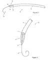
Figure 1 is a schematic diagram in cross-section of an adult aorta showing a prior art deployment assembly fed intraluminally up to the heart; -
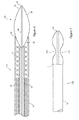
Figure 2 is a schematic diagram in perspective of an embodiment of introducer assembly; -
Figure 3 is an enlarged view of the distal end of the assembly ofFigure 2 ; -
Figure 4 is a view of the distal end of the assembly ofFigure 3 with the dilator tip in a contracted configuration; -
Figure 5 is a view of the distal end of the assembly ofFigure 3 showing the dilator tip withdrawn into a sheath of the assembly; -
Figure 6 is an enlarged cross-sectional view of the embodiment of introducer assembly ofFigures 2 to 5 ; -
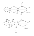
Figures 7 to 9 are schematic diagrams of other embodiments of dilator tip; and -
Figure 10 is a schematic diagram in cross-section of an adult aorta showing the embodiment of deployment assembly ofFigures 2 to 6 fed intraluminally up to the heart. - Referring to
Figure 1 , there is shown in cross-section an example of a thoracic aorta. It will be seen that thethoracic aorta 90 comprises an ascendingaorta 91 which receives blood from the heart through anaortic valve 92. At the upper end of the ascending aorta there are branches for the great vessels, theinnominate artery 93, the left commoncarotid artery 94 and the leftsubclavian artery 95. The aorta after these great vessels is referred to as the descendingaorta 96. - Located within the aorta there is shown a prior
art introducer assembly 10, which typically passes into the patient's vasculature through the femoral artery (not shown) and in this example through the aortic arch to a location just proximate theaortic valve 92. Theintroducer assembly 10 carries an implantablemedical device 12, for instance a stent graft, within a holdingsheath 16. The assembly typically includes apusher member 14 for pushing thedevice 12 to the deployment site or otherwise for holding thedevice 12 within the introducer assembly during the deployment operation. There is also provided at the distal end of the assembly adilator tip 18, of conventional form, which has the function of assisting in curving and guiding theassembly 10 through tortuous vasculature. - It is common for
such assemblies 10 to include a guide wire (not shown) which passes through a central lumen of theassembly 10, as well as in thedilator tip 18, for use in guiding the assembly through the vasculature during the deployment operation. Thedilator tip 18 is typically of a flexible material. Where such a guide wire is provided, there is generally little risk of this damaging the patient's vasculature or organs in light of the very flexible nature of the distal end of the guide wire. It is thus not uncommon for such systems to provide for the guide wire to enter the cardiac chamber through thevalve 92. Thedilator tip 18, on the other hand, is preferably kept clear of thevalve 92, in other words it is preferred in some instances at least not to pass thedilator tip 18 through thevalve 92. The tip is too large and relatively hard for this to be desirable. As a result, in some clinical applications at least, the introducer assembly should not be made to breach the position of thevalve 92. - The
dilator tip 18, which has a minimum effective length to give it the required flexibility, therefore limits the position at which the introducer can be moved towards theheart valve 92, typically to a gap or distance D as shown inFigure 1 . Thus, the implantablemedical device 12 will also only be able to be positioned in the vessel, prior to deployment, by no less than distance D from theaortic valve 92. In practice this distance may be significantly more than D if thedilator tip 18 must be extended out of thesheath 16 in order to clear space for release of thedevice 12. This gap D, therefore, means that thedevice 12 cannot be placed close to the heart. -
Figures 2 to 6 and10 show an embodiment of assembly which can avoid this shortcoming of prior art devices.Figure 7 to 9 show other embodiments of inflatable dilator tip. - Referring first to
Figures 2 and 3 , these show in schematic form the distal end of a preferred embodiment ofintroducer assembly 20. The assembly includes asheath 16 of conventional form and adilator tip 22 which extends beyond thedistal end 24 of thesheath 16. The dilator tip, formed with a radially expandable and contractible element, includes aflexible cannula 26 which extends along a longitudinal axis of the cannula and couples to a lumen in theintroducer assembly 20, for the passage of aguide wire 25 through theassembly 20 and beyond the distal end of thedilator tip 22. The dilator tip also includes aballoon element 28, which is shown in inflated form inFigures 2 and 3 . - As can be seen, shown also in
Figure 6 , thedilator tip 22 when inflated has an outer diameter at the junction with thedistal end 24 of thesheath 16 which is similar to the outer diameter of thesheath 16. The diameter of theballoon 28 can be the same as, a little smaller or a little larger than the diameter of thesheath 16 at itsdistal end 24. In some embodiments, theballoon 28 of thedilator tip 22 may extend also into the lumen of thesheath 16 at itsdistal end 22, although in the preferred embodiment this is shaped in a manner similar to that of conventional dilator tips. - Referring now to
Figure 4 , thedilator tip 22 is shown in a deflated condition. In this condition the dilator tip has a diameter which is significantly smaller than the internal diameter of thesheath 16. As can be seen inFigure 5 , in the deflated condition, thedilator tip 22 is able to be withdrawn into thesheath 16 and in practice through the lumen of the medical device carried in the sheath, as described in further detail below.Figures 4 and 5 also showguide wire 25 extending out of thecannula 26 of thedilator tip 22, as it typically would during the deployment procedure. What is relevant in these Figures, and as is explained in detail below, is that theintroducer assembly 20 has a structure which enables the dilator tip to be withdrawn into thesheath 16 while the implantablemedical device 12 is still located within the introducer and thus before deployment and release of the device. - Referring now to
Figure 6 , this is a cross-sectional view of a preferred embodiment of introducer assembly. The drawing is not to scale and shows the components of the assembly spaced from one another, not as they would be in practice but only for the sake of clarity. - Only the distal end of the
assembly 20 is shown inFigure 6 as the components at its proximal end, that is at the external manipulation end of theassembly 20 and along its intermediate length, will be apparent to the skilled person having regard to the teachings herein. - The
sheath 16 envelops the internal structure of theassembly 20 as well as the implantablemedical device 12, and has the form of a conventional sheath. Thedilator tip 22 has, in this embodiment, a shape when inflated which is analogous to that of a conventional dilator tip, with aproximal end 32 which extends a short distance into thesheath 16 and adistal end 34 which tapers. - Within the
sheath 16 there is provided an implantablemedical device 12. This may be any suitable implantable medical device, examples being stents, stent grafts and so on. There are typically provided within the introducer assembly elements for restraining the implantable medical device, such as restraining wires, holding sleeves and so on. Theintroducer assembly 20 can use any such device holding elements and therefore it is not necessary to describe any particular type of known restraining element herein. - The assembly also includes a
pusher element 38, also of conventional form, which extends from a position at the end of the portion of thecarrier catheter 36 which holds the implantablemedical device 12 to a proximal end of theintroducer assembly 20, typically at the external manipulation end. Thepusher element 38 is also of tubular form having a central lumen therein typically for the passage therethrough of a guide wire and other elements of the introducer assembly. Typically, thepusher element 38 has an outer diameter substantially the same as or just smaller than the inner diameter of thesheath 16. The distal end of thepusher element 38, in this example, provides a shoulder for supporting the distal end of the implantablemedical device 12 and may also be provided with at least one device restraining device or mechanism. - In the preferred embodiment, the
medical device 12 lies within thesheath 16 in such a manner that is provides a lumen extending therewithin. Thedilator tip 22 is able to pass within this lumen when in its deflated or contracted condition. -
Figure 6 also shows an optional carrier cannula orcatheter 36 which is able to accommodate the deflatedballoon assembly 22. As can be seen, theoptional carrier 26 sits within the bore of thepusher element 38 and can be useful in ensuring smooth retraction of theballoon dilator 22. It is envisaged that such acatheter 36 could also provide restraining mechanisms for restraining themedical device 12, if desired. A suitable restraining mechanism could include supports for holding one or more trigger wires for constraining the proximal and/or the distal end of themedical device 12. - The
cannula 26 of theballoon assembly 22 extends within the lumen of thecarrier catheter 36 and typically to the external manipulation end of theintroducer assembly 20. Thecannula 26 has a central lumen for receiving theguide wire 25, as will be apparent with reference toFigures 2 to 5 and the above description. - The
cannula 26 also includes a lumen within its wall structure which ends at aport 40 within the volume of theballoon element 28, as will be apparent inFigure 6 . This lumen and theport 40 are responsible for providing inflation fluid for inflating theballoon element 28 and also for deflating this when it is desired to withdraw theballoon element 28 into thecatheter 36. The cannula may be pulled in a proximal direction to retract the dilation tip into the catheter. - The
balloon element 28, in the example shown inFigure 6 , includes aproximal portion 32 which extends partially into thesheath 16 and beyond thedistal end 24, as well as adistal portion 34 which tapers towards the tip of thedilator element 22. It is preferred that theballoon element 28, when fully inflated, has a tapering shape towards its distal end which is similar to conventional dilator tips, although this is not essential. - When the
balloon assembly 22 is in its inflated condition, theballoon 28 has an outer diameter which is about the same as, slightly smaller than or slightly larger than the outer diameter of thesheath 16, again in a manner which is not dissimilar from prior art dilator tips. Theballoon element 28, however, can deflate to a size which enables it to be withdrawn into thecannula 36 during the deployment process. In use thecannula 26 is pulled back so as to withdraw the entirety of the dilator tip into thecatheter 36. It will be appreciated that when thedilator tip 22 is deflated and withdrawn into thecatheter 36, there is no element of theassembly 20 which extends beyond the distal tip of the distal end of thesheath 24 and, when thesheath 16 itself is withdrawn (that is, pulled back) the distal end of thecarrier catheter 36 and the implantablemedical device 12 form the distal most part of theassembly 20. This differs from prior art assemblies, in which the dilator tip remains the distal most part of the assembly during the deployment procedure and can only be withdrawn once the implantable medical device has been deployed, that is it has been expanded to its deployed state so as to provide a lumen or passage within the interior of the implantable medical device sufficiently large to be able to withdraw the dilator tip and any other components which are distal of the implantable medical device when this is constrained on the introducer assembly. - The structure of
Figure 6 and of all of the embodiments envisaged in this patent application provides a dilator tip arrangement which can be constrained so as to be able to be withdrawn through the implantable medical device while this remains constrained on the introducer assembly and thus enables the implantable medical device to be located much closer to a desired deployment site, as will be described in further detail in connection withFigure 10 . - Referring now to
Figure 7 , there is shown another embodiment of introducer assembly, the distal part only of this being shown in the Figure. The assembly is substantially the same as that shown inFigure 6 and of the other embodiments described in this application, the primary difference being the provision of a dilator tip, still of balloon form, in which the balloon element has at least one radial constriction on an outer surface thereof, in the preferred embodiment by virtue of having a waisted shaped when inflated. Thenarrow waist portion 124 of theballoon element 122 increases the radial flexibility (it is the flexibility in bending) of theballoon assembly 122 when this is inflated and therefore improves the ability of theballoon assembly 122 to curve so as to follow complex lumen anatomies. -
Figure 8 shows another embodiment ofdilator tip 222, in which aninflatable balloon element 128 is provided with twowaists balloon 222 even greater curving flexibility. -
Figure 9 shows an embodiment of dilatortip balloon assembly 322 which is equally provided with two waists ofradial constrictions waists cannula 26 so as to create threeseparate chambers balloon assembly 322. Thecannula 26 is provided with three inflation/deflation lumens, each of which opens to arespective port balloon assembly 322 to be deflated in stages. This would enable, for instance, the retention of a dilator tip portion during movement of the introducer assembly to the deployment site, for example very close to the aortic valve, while progressively deflating the most distal balloon segment so as to withdraw this into thecatheter 36. - Referring now to
Figure 10 , there is shown the embodiment of introducer assembly shown inFigures 2 to 6 (although equally applicable to the other embodiments disclosed herein) located in the thoracic aorta of a patient and in a configuration in which the dilator tip balloon has already been withdrawn into thecatheter element 36 and therefore is within thesheath 16.Figure 10 also shows thesheath 16 in two positions: (a) in dotted outline, in which the sheath is still overlying the implantablemedical device 12, and (b) in solid lines, in which thesheath 16 has been withdrawn so as to expose the implantable medical device. It can be seen fromFigure 10 that since thedilator tip 22 has been withdrawn into theassembly 20, the implantablemedical device 12 can be located very close to theaortic valve 92, in this example, and thus much closer than is possible with prior art devices, a comparison ofFigures 1 and10 showing this quite clearly. - Although the preferred embodiments make use of an inflatable dilator tip, other embodiments are envisaged which use dilator tip of a different structure. The concept can be extended to any structure which is able to be radially compressed so as to be able to be withdrawn into the introducer assembly during the deployment operation, in the manner taught herein. Thus, the dilator tip could be of a compressible material which causes this to compress radially as it is being pulled into the inner catheter. In another embodiment, there could be provided another compressing mechanism, such as restraining wires arranged to close radially in on the tip so as to compress this. Other embodiments are also envisaged.
- It will also be appreciated that although the preferred embodiments focus on an over the wire introducer system, the principles taught herein are equally applicable to introducer systems which do not use a guide wire. In such an event, it is not necessary to provide a
cannula 26 within thedilator tip 22. The dilator tip could be provided with a flexible rod or wire or with no such central component, being made entirely of a balloon element at its distal end. - In place of a radial constriction such as the waist or waists shown in connection with the above described embodiments, the balloon could be provided with at least one radially arranged weakening feature which increases the flexibility of the dilator tip.
Claims (15)
- An introducer assembly (20, 120) including:a dilator tip (22, 222, 322);a sheath (16) having a diameter;an implantable medical device (12) located within said sheath and providing a lumen therewithin when located in said sheath;wherein the dilator tip is formed with a radially expandable and contractible element, wherein said element has an expanded diameter substantially equal to the diameter of the sheath and a contracted diameter smaller than the diameter of the lumen of said implantable medical device, said dilator tip being retractable when in the contracted condition into said lumen.
- An introducer assembly according to claim 1, wherein the element is a balloon (28, 122, 128), said balloon having an inflated diameter substantially no greater than the diameter of the sheath.
- An introducer assembly according to claim 2, wherein the balloon (28, 122, 128) has an inflated diameter substantially the same as the diameter of the sheath.
- An introducer assembly according to claim 2, wherein the balloon (28, 122, 128) has an inflated diameter smaller than the diameter of the sheath.
- An introducer according to any preceding claim, wherein said element forms a distal most part of the introducer assembly.
- An introducer assembly according to any preceding claim, wherein outer surfaces of the dilator tip are formed substantially entirely of said element.
- An introducer assembly according to any preceding claim, wherein the dilator tip is provided with at least one radial constriction (124, 230, 232, 330, 332) on an outer surface thereof operable to increase bending flexibility of the dilator tip.
- An introducer assembly according to claim 7, wherein the or each said radial constriction is formed as a portion of balloon having a smaller expanded diameter.
- An introducer assembly according to any preceding claim, wherein the dilator tip is provided with at least one radially arranged weakening feature which increases bending flexibility of the dilator tip.
- An introducer assembly according to any preceding claim, wherein the element is expandable and/or contractible in stages in a longitudinal direction of the dilator tip.
- An introducer assembly according to any preceding claim, wherein the element is a balloon provided with selective inflation characteristics.
- An introducer assembly according to claim 11, wherein said balloon is provided with a plurality of inflatable compartments (334, 336, 338).
- An introducer assembly according to claim 12, wherein said compartments are separately inflatable.
- An introducer assembly according to any preceding claim, including a dilator tip catheter (36) having an internal diameter; the implantable medical device (12) being located concentrically to and radially outside of said dilator tip catheter; the dilator tip catheter and the implantable medical device being located within said sheath (16); wherein the radially expandable and contractible element of the dilator tip has an expanded diameter substantially equal to the diameter of the sheath and a contracted diameter smaller than the internal diameter of said dilator tip catheter, said dilator tip being retractable when in the contracted condition into said dilator tip catheter (36).
- An introducer assembly according to claim 14, wherein the dilator tip catheter includes at least one restraining mechanism for restraining a proximal and/or a distal end of the medical device.
Applications Claiming Priority (1)
| Application Number | Priority Date | Filing Date | Title |
|---|---|---|---|
| GB1018470.3A GB2485338B (en) | 2010-11-02 | 2010-11-02 | Introducer assembly and dilator tip therefor |
Publications (2)
| Publication Number | Publication Date |
|---|---|
| EP2446915A1 true EP2446915A1 (en) | 2012-05-02 |
| EP2446915B1 EP2446915B1 (en) | 2018-01-24 |
Family
ID=43401645
Family Applications (1)
| Application Number | Title | Priority Date | Filing Date |
|---|---|---|---|
| EP11186119.1A Active EP2446915B1 (en) | 2010-11-02 | 2011-10-21 | Introducer assembly and dilator tip therefor |
Country Status (3)
| Country | Link |
|---|---|
| US (1) | US20120109056A1 (en) |
| EP (1) | EP2446915B1 (en) |
| GB (1) | GB2485338B (en) |
Cited By (36)
| Publication number | Priority date | Publication date | Assignee | Title |
|---|---|---|---|---|
| EP3422966A4 (en) * | 2016-02-29 | 2019-03-13 | Pristine Access Technologies Ltd | REMOVABLE CATHET CAP AND ITS APPLICATIONS |
| EP3490499A2 (en) * | 2016-08-01 | 2019-06-05 | Cardiovalve Ltd | Minimally-invasive delivery systems |
| US10350065B2 (en) | 2006-07-28 | 2019-07-16 | Edwards Lifesciences Cardiaq Llc | Percutaneous valve prosthesis and system and method for implanting the same |
| US10350066B2 (en) | 2015-08-28 | 2019-07-16 | Edwards Lifesciences Cardiaq Llc | Steerable delivery system for replacement mitral valve and methods of use |
| US10376363B2 (en) | 2015-04-30 | 2019-08-13 | Edwards Lifesciences Cardiaq Llc | Replacement mitral valve, delivery system for replacement mitral valve and methods of use |
| US10441412B2 (en) | 2009-04-15 | 2019-10-15 | Edwards Lifesciences Cardiaq Llc | Vascular implant and delivery system |
| US10456277B2 (en) | 2005-11-10 | 2019-10-29 | Edwards Lifesciences Cardiaq Llc | Percutaneous heart valve |
| WO2020115616A1 (en) * | 2018-12-05 | 2020-06-11 | Acclarent, Inc. | Apparatus for maintaining patency of dilated anatomical opening |
| WO2021126934A1 (en) | 2019-12-17 | 2021-06-24 | Surmodics, Inc. | Anchored dilator system and methods for same |
| US11701225B2 (en) | 2014-07-30 | 2023-07-18 | Cardiovalve Ltd. | Delivery of a prosthetic valve |
| US11793635B2 (en) | 2015-02-05 | 2023-10-24 | Cardiovalve Ltd. | Prosthetic valve with angularly offset frames |
| US11801135B2 (en) | 2015-02-05 | 2023-10-31 | Cardiovalve Ltd. | Techniques for deployment of a prosthetic valve |
| US11819405B2 (en) | 2017-09-19 | 2023-11-21 | Cardiovalve Ltd. | Prosthetic valve with inflatable cuff configured for radial extension |
| US11839541B2 (en) | 2009-12-08 | 2023-12-12 | Cardiovalve Ltd. | Prosthetic heart valve with upper skirt |
| US11844691B2 (en) | 2013-01-24 | 2023-12-19 | Cardiovalve Ltd. | Partially-covered prosthetic valves |
| US11883293B2 (en) | 2018-09-17 | 2024-01-30 | Cardiovalve Ltd. | Leaflet-grouping system |
| US11937795B2 (en) | 2016-02-16 | 2024-03-26 | Cardiovalve Ltd. | Techniques for providing a replacement valve and transseptal communication |
| US11969163B2 (en) | 2010-07-21 | 2024-04-30 | Cardiovalve Ltd. | Valve prosthesis configured for deployment in annular spacer |
| US11980547B2 (en) | 2017-10-19 | 2024-05-14 | Cardiovalve Ltd. | Techniques for use with prosthetic valve leaflets |
| US12029646B2 (en) | 2017-08-03 | 2024-07-09 | Cardiovalve Ltd. | Prosthetic heart valve |
| US12090048B2 (en) | 2017-08-03 | 2024-09-17 | Cardiovalve Ltd. | Prosthetic heart valve |
| US12138160B2 (en) | 2014-11-26 | 2024-11-12 | Edwards Lifesciences Corporation | Transcatheter prosthetic heart valve and delivery system |
| US12167963B2 (en) | 2010-03-10 | 2024-12-17 | Cardiovalve Ltd. | Method for use at a heart valve |
| US12285330B2 (en) | 2013-03-14 | 2025-04-29 | Edwards Lifesciences Cardiaq Llc | Prosthesis for atraumatically grasping intralumenal tissue and methods of delivery |
| US12295839B2 (en) | 2019-04-23 | 2025-05-13 | Edwards Lifesciences Corporation | Motorized implant delivery system |
| US12303385B2 (en) | 2013-02-04 | 2025-05-20 | Edwards Lifesciences Corporation | Method of implanting a spacer body in a mitral valve |
| US12310853B2 (en) | 2014-09-28 | 2025-05-27 | Edwards Lifesciences Corporation | Systems and methods for treating cardiac dysfunction |
| US12357459B2 (en) | 2020-12-03 | 2025-07-15 | Cardiovalve Ltd. | Transluminal delivery system |
| US12376961B2 (en) | 2008-05-01 | 2025-08-05 | Edwards Lifesciences Corporation | Method of implanting a prosthetic heart valve assembly |
| US12409031B2 (en) | 2009-12-04 | 2025-09-09 | Edwards Lifesciences Corporation | Prosthetic valve having a multi-part frame |
| US12427016B2 (en) | 2009-04-29 | 2025-09-30 | Edwards Lifesciences Corporation | Apparatus and method for replacing a diseased cardiac valve |
| US12447014B2 (en) | 2019-04-12 | 2025-10-21 | Edwards Lifesciences Corporation | Valve with multi-part frame and associated resilient bridging features |
| US12447011B2 (en) | 2016-07-21 | 2025-10-21 | Edwards Lifesciences Corporation | Replacement heart valve prosthesis |
| US12458493B2 (en) | 2017-09-19 | 2025-11-04 | Cardiovalve Ltd. | Prosthetic heart valve and delivery systems and methods |
| US12533233B2 (en) | 2021-10-27 | 2026-01-27 | Edwards Lifesciences Corporation | System and method for crimping and loading a prosthetic heart valve |
| US12551207B2 (en) | 2008-11-21 | 2026-02-17 | Percutaneous Cardiovascular Solutions Pty Ltd | Heart valve prosthesis and method |
Families Citing this family (44)
| Publication number | Priority date | Publication date | Assignee | Title |
|---|---|---|---|---|
| CA2580053C (en) | 2004-09-14 | 2014-07-08 | Edwards Lifesciences Ag. | Device and method for treatment of heart valve regurgitation |
| EP2491891A3 (en) | 2004-10-02 | 2013-03-20 | Endoheart AG | Devices for embolic protection and mitral valve repair |
| AU2009295960A1 (en) | 2008-09-29 | 2010-04-01 | Cardiaq Valve Technologies, Inc. | Heart valve |
| US9730790B2 (en) | 2009-09-29 | 2017-08-15 | Edwards Lifesciences Cardiaq Llc | Replacement valve and method |
| US8579964B2 (en) | 2010-05-05 | 2013-11-12 | Neovasc Inc. | Transcatheter mitral valve prosthesis |
| EP2582326B2 (en) | 2010-06-21 | 2024-07-03 | Edwards Lifesciences CardiAQ LLC | Replacement heart valve |
| WO2012040655A2 (en) | 2010-09-23 | 2012-03-29 | Cardiaq Valve Technologies, Inc. | Replacement heart valves, delivery devices and methods |
| US12502276B2 (en) | 2011-05-16 | 2025-12-23 | Edwards Lifesciences Corporation | Inversion delivery device and method for a prosthesis |
| JP6272781B2 (en) | 2012-01-06 | 2018-01-31 | エンボライン, インコーポレイテッド | Integrated embolic protection device |
| JPWO2014115273A1 (en) * | 2013-01-23 | 2017-01-19 | テルモ株式会社 | Self-expanding stent system |
| US9855160B2 (en) | 2013-03-14 | 2018-01-02 | W. L. Gore & Associates, Inc. | Endoprosthesis delivery systems with deployment aids |
| US9730791B2 (en) | 2013-03-14 | 2017-08-15 | Edwards Lifesciences Cardiaq Llc | Prosthesis for atraumatically grasping intralumenal tissue and methods of delivery |
| CN105358206B (en) | 2013-06-04 | 2019-03-12 | 迈克尔·加布里埃尔·塔尔 | Double-tip hemodialysis catheter |
| EP3107497B1 (en) | 2014-02-21 | 2020-07-22 | Edwards Lifesciences CardiAQ LLC | Delivery device for controlled deployment of a replacement valve |
| CA3161000A1 (en) | 2014-05-19 | 2015-11-26 | Edwards Lifesciences Cardiaq Llc | Replacement mitral valve with annular flap |
| US9532870B2 (en) | 2014-06-06 | 2017-01-03 | Edwards Lifesciences Corporation | Prosthetic valve for replacing a mitral valve |
| US9808598B2 (en) | 2015-02-04 | 2017-11-07 | Teleflex Medical Incorporated | Flexible tip dilator |
| US10478591B2 (en) | 2015-03-05 | 2019-11-19 | Cook Medical Technologies Llc | Stent graft delivery device pre-loaded with a single wire for device tracking and cannulation |
| US10426646B2 (en) | 2015-03-05 | 2019-10-01 | Cook Medical Technologies Llc | Pre-loaded delivery device with tri-fold proximal prosthesis attachment |
| WO2016153918A1 (en) | 2015-03-20 | 2016-09-29 | Cardiokinetix, Inc. | Systems and methods for delivering an implantable device |
| US10441416B2 (en) | 2015-04-21 | 2019-10-15 | Edwards Lifesciences Corporation | Percutaneous mitral valve replacement device |
| CA2990872C (en) | 2015-06-22 | 2022-03-22 | Edwards Lifescience Cardiaq Llc | Actively controllable heart valve implant and methods of controlling same |
| US10092400B2 (en) | 2015-06-23 | 2018-10-09 | Edwards Lifesciences Cardiaq Llc | Systems and methods for anchoring and sealing a prosthetic heart valve |
| KR102579711B1 (en) | 2015-07-20 | 2023-09-15 | 프리스틴 어세스 테크놀로지스 리미티드 | Hemodialysis catheter with corrugated tip |
| US10117744B2 (en) | 2015-08-26 | 2018-11-06 | Edwards Lifesciences Cardiaq Llc | Replacement heart valves and methods of delivery |
| US10575951B2 (en) | 2015-08-26 | 2020-03-03 | Edwards Lifesciences Cardiaq Llc | Delivery device and methods of use for transapical delivery of replacement mitral valve |
| US10322020B2 (en) * | 2015-09-18 | 2019-06-18 | Terumo Corporation | Pushable implant delivery system |
| US10617509B2 (en) | 2015-12-29 | 2020-04-14 | Emboline, Inc. | Multi-access intraprocedural embolic protection device |
| CN109843219B (en) | 2016-08-26 | 2022-04-05 | 爱德华兹生命科学公司 | Multi-part replacement heart valve prosthesis |
| IL269007B (en) | 2017-03-10 | 2022-08-01 | Abiomed Inc | Expandable introducer sheath for medical device |
| CA3067150A1 (en) | 2017-07-06 | 2019-01-10 | Edwards Lifesciences Corporation | Steerable rail delivery system |
| CA3078699C (en) | 2017-10-13 | 2023-10-10 | W.L. Gore & Associates, Inc. | Telescoping prosthetic valve and delivery system |
| CN111818877B (en) | 2018-01-25 | 2023-12-22 | 爱德华兹生命科学公司 | Delivery system for assisting replacement valve recapture and repositioning after deployment |
| CN111971086B (en) | 2018-02-15 | 2023-12-22 | 阿比奥梅德公司 | Expandable introducer sheaths for medical devices |
| US11051934B2 (en) | 2018-02-28 | 2021-07-06 | Edwards Lifesciences Corporation | Prosthetic mitral valve with improved anchors and seal |
| ES3067360T3 (en) | 2018-08-14 | 2026-05-21 | Abiomed Inc | Expandable introducer sheath for medical device |
| EP3921012A1 (en) | 2019-02-04 | 2021-12-15 | Edwards Lifesciences Corporation | Guide wire apparatuses and methods |
| WO2020168091A1 (en) | 2019-02-13 | 2020-08-20 | Emboline, Inc. | Catheter with integrated embolic protection device |
| EP4606414A3 (en) | 2020-02-03 | 2025-12-17 | Abiomed, Inc. | Expandable sheath with interlock dilator |
| WO2022132569A1 (en) | 2020-12-18 | 2022-06-23 | Edwards Lifesciences Corporation | Storage jar assembly for aprosthetic heart valve |
| KR20230147061A (en) | 2021-02-19 | 2023-10-20 | 엠볼린, 인크. | Method and system for placing embolic filters in the aortic arch |
| AU2022381919A1 (en) * | 2021-11-04 | 2024-05-16 | V-Wave Ltd. | Systems for delivering devices for regulating blood pressure across an atrial septum |
| US11813386B2 (en) | 2022-04-14 | 2023-11-14 | V-Wave Ltd. | Interatrial shunt with expanded neck region |
| US20240009442A1 (en) * | 2022-07-05 | 2024-01-11 | Puzzle Medical Devices Inc. | Percutaneous assembly and methods of using same |
Citations (1)
| Publication number | Priority date | Publication date | Assignee | Title |
|---|---|---|---|---|
| WO2010078077A1 (en) * | 2008-12-30 | 2010-07-08 | Wilson-Cook Medical Inc. | Balloon-tipped endoscopic system |
Family Cites Families (3)
| Publication number | Priority date | Publication date | Assignee | Title |
|---|---|---|---|---|
| US7780723B2 (en) * | 2005-06-13 | 2010-08-24 | Edwards Lifesciences Corporation | Heart valve delivery system |
| US8133266B2 (en) * | 2007-04-12 | 2012-03-13 | Medtronic Vascular, Inc. | Expandable tip delivery system and method |
| US20090264859A1 (en) * | 2008-04-21 | 2009-10-22 | Medtronic Vascular, Inc. | Catheter Having a Selectively Expandable Distal Tip |
-
2010
- 2010-11-02 GB GB1018470.3A patent/GB2485338B/en active Active
-
2011
- 2011-10-21 EP EP11186119.1A patent/EP2446915B1/en active Active
- 2011-11-01 US US13/286,759 patent/US20120109056A1/en not_active Abandoned
Patent Citations (1)
| Publication number | Priority date | Publication date | Assignee | Title |
|---|---|---|---|---|
| WO2010078077A1 (en) * | 2008-12-30 | 2010-07-08 | Wilson-Cook Medical Inc. | Balloon-tipped endoscopic system |
Cited By (53)
| Publication number | Priority date | Publication date | Assignee | Title |
|---|---|---|---|---|
| US10456277B2 (en) | 2005-11-10 | 2019-10-29 | Edwards Lifesciences Cardiaq Llc | Percutaneous heart valve |
| US10350065B2 (en) | 2006-07-28 | 2019-07-16 | Edwards Lifesciences Cardiaq Llc | Percutaneous valve prosthesis and system and method for implanting the same |
| US12376961B2 (en) | 2008-05-01 | 2025-08-05 | Edwards Lifesciences Corporation | Method of implanting a prosthetic heart valve assembly |
| US12551207B2 (en) | 2008-11-21 | 2026-02-17 | Percutaneous Cardiovascular Solutions Pty Ltd | Heart valve prosthesis and method |
| US10441412B2 (en) | 2009-04-15 | 2019-10-15 | Edwards Lifesciences Cardiaq Llc | Vascular implant and delivery system |
| US12427016B2 (en) | 2009-04-29 | 2025-09-30 | Edwards Lifesciences Corporation | Apparatus and method for replacing a diseased cardiac valve |
| US12409031B2 (en) | 2009-12-04 | 2025-09-09 | Edwards Lifesciences Corporation | Prosthetic valve having a multi-part frame |
| US12569335B2 (en) | 2009-12-08 | 2026-03-10 | Cardiovalve Ltd. | Prosthetic heart valve with frames |
| US11839541B2 (en) | 2009-12-08 | 2023-12-12 | Cardiovalve Ltd. | Prosthetic heart valve with upper skirt |
| US12167963B2 (en) | 2010-03-10 | 2024-12-17 | Cardiovalve Ltd. | Method for use at a heart valve |
| US11969163B2 (en) | 2010-07-21 | 2024-04-30 | Cardiovalve Ltd. | Valve prosthesis configured for deployment in annular spacer |
| US11844691B2 (en) | 2013-01-24 | 2023-12-19 | Cardiovalve Ltd. | Partially-covered prosthetic valves |
| US12357453B2 (en) | 2013-02-04 | 2025-07-15 | Edwards Lifesciences Corporation | Prosthetic heart valve with atrial sealing member |
| US12303385B2 (en) | 2013-02-04 | 2025-05-20 | Edwards Lifesciences Corporation | Method of implanting a spacer body in a mitral valve |
| US12285330B2 (en) | 2013-03-14 | 2025-04-29 | Edwards Lifesciences Cardiaq Llc | Prosthesis for atraumatically grasping intralumenal tissue and methods of delivery |
| US11872130B2 (en) | 2014-07-30 | 2024-01-16 | Cardiovalve Ltd. | Prosthetic heart valve implant |
| US11701225B2 (en) | 2014-07-30 | 2023-07-18 | Cardiovalve Ltd. | Delivery of a prosthetic valve |
| US12053380B2 (en) | 2014-07-30 | 2024-08-06 | Cardiovalve Ltd. | Anchoring of a prosthetic valve |
| US12310853B2 (en) | 2014-09-28 | 2025-05-27 | Edwards Lifesciences Corporation | Systems and methods for treating cardiac dysfunction |
| US12138160B2 (en) | 2014-11-26 | 2024-11-12 | Edwards Lifesciences Corporation | Transcatheter prosthetic heart valve and delivery system |
| US11793635B2 (en) | 2015-02-05 | 2023-10-24 | Cardiovalve Ltd. | Prosthetic valve with angularly offset frames |
| US11801135B2 (en) | 2015-02-05 | 2023-10-31 | Cardiovalve Ltd. | Techniques for deployment of a prosthetic valve |
| US12396851B2 (en) | 2015-02-05 | 2025-08-26 | Cardiovalve Ltd. | Prosthetic valve with arms and flanges |
| US11793638B2 (en) | 2015-02-05 | 2023-10-24 | Cardiovalve Ltd. | Prosthetic valve with pivoting tissue anchor portions |
| US10376363B2 (en) | 2015-04-30 | 2019-08-13 | Edwards Lifesciences Cardiaq Llc | Replacement mitral valve, delivery system for replacement mitral valve and methods of use |
| US10350066B2 (en) | 2015-08-28 | 2019-07-16 | Edwards Lifesciences Cardiaq Llc | Steerable delivery system for replacement mitral valve and methods of use |
| US11937795B2 (en) | 2016-02-16 | 2024-03-26 | Cardiovalve Ltd. | Techniques for providing a replacement valve and transseptal communication |
| EP3422966A4 (en) * | 2016-02-29 | 2019-03-13 | Pristine Access Technologies Ltd | REMOVABLE CATHET CAP AND ITS APPLICATIONS |
| EP3718591A1 (en) * | 2016-02-29 | 2020-10-07 | Pristine Access Technologies Ltd | Removable catheter cap and applications thereof |
| US12447011B2 (en) | 2016-07-21 | 2025-10-21 | Edwards Lifesciences Corporation | Replacement heart valve prosthesis |
| EP3490499A2 (en) * | 2016-08-01 | 2019-06-05 | Cardiovalve Ltd | Minimally-invasive delivery systems |
| EP3490499B1 (en) * | 2016-08-01 | 2026-02-18 | Cardiovalve Ltd. | Minimally-invasive delivery systems |
| US12611305B2 (en) | 2016-08-01 | 2026-04-28 | Cardiovalve Ltd. | Minimally-invasive delivery systems |
| US12053379B2 (en) | 2016-08-01 | 2024-08-06 | Cardiovalve Ltd. | Minimally-invasive delivery systems |
| US12232958B2 (en) | 2017-08-03 | 2025-02-25 | Cardiovalve Ltd. | Prosthetic heart valve |
| US12064347B2 (en) | 2017-08-03 | 2024-08-20 | Cardiovalve Ltd. | Prosthetic heart valve |
| US12090048B2 (en) | 2017-08-03 | 2024-09-17 | Cardiovalve Ltd. | Prosthetic heart valve |
| US12029646B2 (en) | 2017-08-03 | 2024-07-09 | Cardiovalve Ltd. | Prosthetic heart valve |
| US12023243B2 (en) | 2017-09-19 | 2024-07-02 | Cardiovalve Ltd. | Prosthetic valve with protective fabric covering around tissue anchor bases |
| US11819405B2 (en) | 2017-09-19 | 2023-11-21 | Cardiovalve Ltd. | Prosthetic valve with inflatable cuff configured for radial extension |
| US12458493B2 (en) | 2017-09-19 | 2025-11-04 | Cardiovalve Ltd. | Prosthetic heart valve and delivery systems and methods |
| US11864996B2 (en) | 2017-09-19 | 2024-01-09 | Cardiovalve Ltd. | Prosthetic valve with protective sleeve around an outlet rim |
| US11980547B2 (en) | 2017-10-19 | 2024-05-14 | Cardiovalve Ltd. | Techniques for use with prosthetic valve leaflets |
| US11883293B2 (en) | 2018-09-17 | 2024-01-30 | Cardiovalve Ltd. | Leaflet-grouping system |
| US11583393B2 (en) | 2018-12-05 | 2023-02-21 | Acclarent, Inc. | Apparatus and method to maintain patency of dilated anatomical opening |
| WO2020115616A1 (en) * | 2018-12-05 | 2020-06-11 | Acclarent, Inc. | Apparatus for maintaining patency of dilated anatomical opening |
| US12447014B2 (en) | 2019-04-12 | 2025-10-21 | Edwards Lifesciences Corporation | Valve with multi-part frame and associated resilient bridging features |
| US12295839B2 (en) | 2019-04-23 | 2025-05-13 | Edwards Lifesciences Corporation | Motorized implant delivery system |
| WO2021126934A1 (en) | 2019-12-17 | 2021-06-24 | Surmodics, Inc. | Anchored dilator system and methods for same |
| EP4076615A4 (en) * | 2019-12-17 | 2023-06-21 | Surmodics, Inc. | ANCHORED DILATOR SYSTEM AND RELATED METHODS |
| US11980730B2 (en) | 2019-12-17 | 2024-05-14 | Surmodics, Inc. | Anchored dilator system and methods for same |
| US12357459B2 (en) | 2020-12-03 | 2025-07-15 | Cardiovalve Ltd. | Transluminal delivery system |
| US12533233B2 (en) | 2021-10-27 | 2026-01-27 | Edwards Lifesciences Corporation | System and method for crimping and loading a prosthetic heart valve |
Also Published As
| Publication number | Publication date |
|---|---|
| GB2485338A (en) | 2012-05-16 |
| GB2485338B (en) | 2012-12-05 |
| US20120109056A1 (en) | 2012-05-03 |
| EP2446915B1 (en) | 2018-01-24 |
| GB201018470D0 (en) | 2010-12-15 |
Similar Documents
| Publication | Publication Date | Title |
|---|---|---|
| EP2446915B1 (en) | Introducer assembly and dilator tip therefor | |
| US12186509B2 (en) | Intravascular delivery system and method for percutaneous coronary intervention | |
| EP2893907B1 (en) | A delivery device for an insertable medical device | |
| US6669718B2 (en) | Apparatus and method for placing bifurcated stents | |
| US5868779A (en) | Apparatus and methods for dilating vessels and hollow-body organs | |
| US5980533A (en) | Stent delivery system | |
| US8986365B2 (en) | Delivery system with retractable proximal end | |
| JP4351536B2 (en) | Self-expanding stent delivery system used in bifurcated vessels | |
| CN103153384B (en) | For the device of device in the delivery of vascular of chamber | |
| EP3245985A1 (en) | Implantable medical device delivery system | |
| US20230119898A1 (en) | Tubular medical device | |
| US20100298922A1 (en) | Angioplasty Assembly | |
| US20160256304A1 (en) | Stent graft delivery device pre-loaded with a single wire for device tracking and cannulation | |
| WO2002056799A2 (en) | Introducer for deployment of branched prosthesis | |
| US8021409B2 (en) | Deployment catheter | |
| US9387102B2 (en) | Sheathless predilatation angioplasty and stent deployment catheter | |
| JP2010528802A (en) | Bifurcated balloon & stent delivery system | |
| US9668899B2 (en) | Rapid exchange sheathless predilatation angioplasty and stent deployment catheter | |
| EP3416595A1 (en) | Rapid exchange sheathless predilatation angioplasty and stent deployment catheter | |
| US10278850B2 (en) | Stent deployment and postdilatation non-compliant balloon catheter and methods of use | |
| WO2001095976A1 (en) | Stent delivery system | |
| IE86053B1 (en) | An angioplasty assembly |
Legal Events
| Date | Code | Title | Description |
|---|---|---|---|
| PUAI | Public reference made under article 153(3) epc to a published international application that has entered the european phase |
Free format text: ORIGINAL CODE: 0009012 |
|
| AK | Designated contracting states |
Kind code of ref document: A1 Designated state(s): AL AT BE BG CH CY CZ DE DK EE ES FI FR GB GR HR HU IE IS IT LI LT LU LV MC MK MT NL NO PL PT RO RS SE SI SK SM TR |
|
| AX | Request for extension of the european patent |
Extension state: BA ME |
|
| 17P | Request for examination filed |
Effective date: 20121023 |
|
| 17Q | First examination report despatched |
Effective date: 20150325 |
|
| GRAP | Despatch of communication of intention to grant a patent |
Free format text: ORIGINAL CODE: EPIDOSNIGR1 |
|
| STAA | Information on the status of an ep patent application or granted ep patent |
Free format text: STATUS: GRANT OF PATENT IS INTENDED |
|
| RIC1 | Information provided on ipc code assigned before grant |
Ipc: A61M 25/00 20060101AFI20170519BHEP Ipc: A61M 25/10 20130101ALI20170519BHEP |
|
| INTG | Intention to grant announced |
Effective date: 20170616 |
|
| GRAJ | Information related to disapproval of communication of intention to grant by the applicant or resumption of examination proceedings by the epo deleted |
Free format text: ORIGINAL CODE: EPIDOSDIGR1 |
|
| STAA | Information on the status of an ep patent application or granted ep patent |
Free format text: STATUS: EXAMINATION IS IN PROGRESS |
|
| REG | Reference to a national code |
Ref country code: DE Ref legal event code: R079 Ref document number: 602011045250 Country of ref document: DE Free format text: PREVIOUS MAIN CLASS: A61M0025000000 Ipc: A61M0025100000 |
|
| INTC | Intention to grant announced (deleted) | ||
| GRAP | Despatch of communication of intention to grant a patent |
Free format text: ORIGINAL CODE: EPIDOSNIGR1 |
|
| STAA | Information on the status of an ep patent application or granted ep patent |
Free format text: STATUS: GRANT OF PATENT IS INTENDED |
|
| RIC1 | Information provided on ipc code assigned before grant |
Ipc: A61M 25/00 20060101ALI20170824BHEP Ipc: A61M 25/06 20060101ALI20170824BHEP Ipc: A61M 29/02 20060101ALI20170824BHEP Ipc: A61M 25/10 20130101AFI20170824BHEP Ipc: A61F 2/966 20130101ALI20170824BHEP |
|
| INTG | Intention to grant announced |
Effective date: 20170919 |
|
| RBV | Designated contracting states (corrected) |
Designated state(s): AL AT BE BG CH CY CZ DE DK EE ES FI FR GR HR HU IE IS IT LI LT LU LV MC MK MT NL NO PL PT RO RS SE SI SK SM TR |
|
| GRAS | Grant fee paid |
Free format text: ORIGINAL CODE: EPIDOSNIGR3 |
|
| GRAA | (expected) grant |
Free format text: ORIGINAL CODE: 0009210 |
|
| STAA | Information on the status of an ep patent application or granted ep patent |
Free format text: STATUS: THE PATENT HAS BEEN GRANTED |
|
| AK | Designated contracting states |
Kind code of ref document: B1 Designated state(s): AL AT BE BG CH CY CZ DE DK EE ES FI FR GR HR HU IE IS IT LI LT LU LV MC MK MT NL NO PL PT RO RS SE SI SK SM TR |
|
| REG | Reference to a national code |
Ref country code: CH Ref legal event code: EP |
|
| REG | Reference to a national code |
Ref country code: AT Ref legal event code: REF Ref document number: 965435 Country of ref document: AT Kind code of ref document: T Effective date: 20180215 |
|
| REG | Reference to a national code |
Ref country code: IE Ref legal event code: FG4D |
|
| REG | Reference to a national code |
Ref country code: DE Ref legal event code: R096 Ref document number: 602011045250 Country of ref document: DE |
|
| REG | Reference to a national code |
Ref country code: NL Ref legal event code: MP Effective date: 20180124 |
|
| REG | Reference to a national code |
Ref country code: LT Ref legal event code: MG4D |
|
| REG | Reference to a national code |
Ref country code: AT Ref legal event code: MK05 Ref document number: 965435 Country of ref document: AT Kind code of ref document: T Effective date: 20180124 |
|
| PG25 | Lapsed in a contracting state [announced via postgrant information from national office to epo] |
Ref country code: NL Free format text: LAPSE BECAUSE OF FAILURE TO SUBMIT A TRANSLATION OF THE DESCRIPTION OR TO PAY THE FEE WITHIN THE PRESCRIBED TIME-LIMIT Effective date: 20180124 |
|
| PG25 | Lapsed in a contracting state [announced via postgrant information from national office to epo] |
Ref country code: NO Free format text: LAPSE BECAUSE OF FAILURE TO SUBMIT A TRANSLATION OF THE DESCRIPTION OR TO PAY THE FEE WITHIN THE PRESCRIBED TIME-LIMIT Effective date: 20180424 Ref country code: LT Free format text: LAPSE BECAUSE OF FAILURE TO SUBMIT A TRANSLATION OF THE DESCRIPTION OR TO PAY THE FEE WITHIN THE PRESCRIBED TIME-LIMIT Effective date: 20180124 Ref country code: FI Free format text: LAPSE BECAUSE OF FAILURE TO SUBMIT A TRANSLATION OF THE DESCRIPTION OR TO PAY THE FEE WITHIN THE PRESCRIBED TIME-LIMIT Effective date: 20180124 Ref country code: HR Free format text: LAPSE BECAUSE OF FAILURE TO SUBMIT A TRANSLATION OF THE DESCRIPTION OR TO PAY THE FEE WITHIN THE PRESCRIBED TIME-LIMIT Effective date: 20180124 Ref country code: ES Free format text: LAPSE BECAUSE OF FAILURE TO SUBMIT A TRANSLATION OF THE DESCRIPTION OR TO PAY THE FEE WITHIN THE PRESCRIBED TIME-LIMIT Effective date: 20180124 Ref country code: CY Free format text: LAPSE BECAUSE OF FAILURE TO SUBMIT A TRANSLATION OF THE DESCRIPTION OR TO PAY THE FEE WITHIN THE PRESCRIBED TIME-LIMIT Effective date: 20180124 |
|
| PG25 | Lapsed in a contracting state [announced via postgrant information from national office to epo] |
Ref country code: RS Free format text: LAPSE BECAUSE OF FAILURE TO SUBMIT A TRANSLATION OF THE DESCRIPTION OR TO PAY THE FEE WITHIN THE PRESCRIBED TIME-LIMIT Effective date: 20180124 Ref country code: LV Free format text: LAPSE BECAUSE OF FAILURE TO SUBMIT A TRANSLATION OF THE DESCRIPTION OR TO PAY THE FEE WITHIN THE PRESCRIBED TIME-LIMIT Effective date: 20180124 Ref country code: IS Free format text: LAPSE BECAUSE OF FAILURE TO SUBMIT A TRANSLATION OF THE DESCRIPTION OR TO PAY THE FEE WITHIN THE PRESCRIBED TIME-LIMIT Effective date: 20180524 Ref country code: SE Free format text: LAPSE BECAUSE OF FAILURE TO SUBMIT A TRANSLATION OF THE DESCRIPTION OR TO PAY THE FEE WITHIN THE PRESCRIBED TIME-LIMIT Effective date: 20180124 Ref country code: GR Free format text: LAPSE BECAUSE OF FAILURE TO SUBMIT A TRANSLATION OF THE DESCRIPTION OR TO PAY THE FEE WITHIN THE PRESCRIBED TIME-LIMIT Effective date: 20180425 Ref country code: PL Free format text: LAPSE BECAUSE OF FAILURE TO SUBMIT A TRANSLATION OF THE DESCRIPTION OR TO PAY THE FEE WITHIN THE PRESCRIBED TIME-LIMIT Effective date: 20180124 Ref country code: BG Free format text: LAPSE BECAUSE OF FAILURE TO SUBMIT A TRANSLATION OF THE DESCRIPTION OR TO PAY THE FEE WITHIN THE PRESCRIBED TIME-LIMIT Effective date: 20180424 Ref country code: AT Free format text: LAPSE BECAUSE OF FAILURE TO SUBMIT A TRANSLATION OF THE DESCRIPTION OR TO PAY THE FEE WITHIN THE PRESCRIBED TIME-LIMIT Effective date: 20180124 |
|
| REG | Reference to a national code |
Ref country code: DE Ref legal event code: R097 Ref document number: 602011045250 Country of ref document: DE |
|
| PG25 | Lapsed in a contracting state [announced via postgrant information from national office to epo] |
Ref country code: EE Free format text: LAPSE BECAUSE OF FAILURE TO SUBMIT A TRANSLATION OF THE DESCRIPTION OR TO PAY THE FEE WITHIN THE PRESCRIBED TIME-LIMIT Effective date: 20180124 Ref country code: AL Free format text: LAPSE BECAUSE OF FAILURE TO SUBMIT A TRANSLATION OF THE DESCRIPTION OR TO PAY THE FEE WITHIN THE PRESCRIBED TIME-LIMIT Effective date: 20180124 Ref country code: IT Free format text: LAPSE BECAUSE OF FAILURE TO SUBMIT A TRANSLATION OF THE DESCRIPTION OR TO PAY THE FEE WITHIN THE PRESCRIBED TIME-LIMIT Effective date: 20180124 Ref country code: RO Free format text: LAPSE BECAUSE OF FAILURE TO SUBMIT A TRANSLATION OF THE DESCRIPTION OR TO PAY THE FEE WITHIN THE PRESCRIBED TIME-LIMIT Effective date: 20180124 |
|
| PG25 | Lapsed in a contracting state [announced via postgrant information from national office to epo] |
Ref country code: CZ Free format text: LAPSE BECAUSE OF FAILURE TO SUBMIT A TRANSLATION OF THE DESCRIPTION OR TO PAY THE FEE WITHIN THE PRESCRIBED TIME-LIMIT Effective date: 20180124 Ref country code: SK Free format text: LAPSE BECAUSE OF FAILURE TO SUBMIT A TRANSLATION OF THE DESCRIPTION OR TO PAY THE FEE WITHIN THE PRESCRIBED TIME-LIMIT Effective date: 20180124 Ref country code: DK Free format text: LAPSE BECAUSE OF FAILURE TO SUBMIT A TRANSLATION OF THE DESCRIPTION OR TO PAY THE FEE WITHIN THE PRESCRIBED TIME-LIMIT Effective date: 20180124 Ref country code: SM Free format text: LAPSE BECAUSE OF FAILURE TO SUBMIT A TRANSLATION OF THE DESCRIPTION OR TO PAY THE FEE WITHIN THE PRESCRIBED TIME-LIMIT Effective date: 20180124 |
|
| PLBE | No opposition filed within time limit |
Free format text: ORIGINAL CODE: 0009261 |
|
| STAA | Information on the status of an ep patent application or granted ep patent |
Free format text: STATUS: NO OPPOSITION FILED WITHIN TIME LIMIT |
|
| 26N | No opposition filed |
Effective date: 20181025 |
|
| PG25 | Lapsed in a contracting state [announced via postgrant information from national office to epo] |
Ref country code: SI Free format text: LAPSE BECAUSE OF FAILURE TO SUBMIT A TRANSLATION OF THE DESCRIPTION OR TO PAY THE FEE WITHIN THE PRESCRIBED TIME-LIMIT Effective date: 20180124 |
|
| REG | Reference to a national code |
Ref country code: CH Ref legal event code: PL |
|
| REG | Reference to a national code |
Ref country code: BE Ref legal event code: MM Effective date: 20181031 |
|
| PG25 | Lapsed in a contracting state [announced via postgrant information from national office to epo] |
Ref country code: MC Free format text: LAPSE BECAUSE OF FAILURE TO SUBMIT A TRANSLATION OF THE DESCRIPTION OR TO PAY THE FEE WITHIN THE PRESCRIBED TIME-LIMIT Effective date: 20180124 Ref country code: LU Free format text: LAPSE BECAUSE OF NON-PAYMENT OF DUE FEES Effective date: 20181021 |
|
| PG25 | Lapsed in a contracting state [announced via postgrant information from national office to epo] |
Ref country code: CH Free format text: LAPSE BECAUSE OF NON-PAYMENT OF DUE FEES Effective date: 20181031 Ref country code: FR Free format text: LAPSE BECAUSE OF NON-PAYMENT OF DUE FEES Effective date: 20181031 Ref country code: BE Free format text: LAPSE BECAUSE OF NON-PAYMENT OF DUE FEES Effective date: 20181031 Ref country code: LI Free format text: LAPSE BECAUSE OF NON-PAYMENT OF DUE FEES Effective date: 20181031 |
|
| PG25 | Lapsed in a contracting state [announced via postgrant information from national office to epo] |
Ref country code: MT Free format text: LAPSE BECAUSE OF NON-PAYMENT OF DUE FEES Effective date: 20181021 |
|
| PG25 | Lapsed in a contracting state [announced via postgrant information from national office to epo] |
Ref country code: TR Free format text: LAPSE BECAUSE OF FAILURE TO SUBMIT A TRANSLATION OF THE DESCRIPTION OR TO PAY THE FEE WITHIN THE PRESCRIBED TIME-LIMIT Effective date: 20180124 |
|
| PG25 | Lapsed in a contracting state [announced via postgrant information from national office to epo] |
Ref country code: PT Free format text: LAPSE BECAUSE OF FAILURE TO SUBMIT A TRANSLATION OF THE DESCRIPTION OR TO PAY THE FEE WITHIN THE PRESCRIBED TIME-LIMIT Effective date: 20180124 |
|
| PG25 | Lapsed in a contracting state [announced via postgrant information from national office to epo] |
Ref country code: MK Free format text: LAPSE BECAUSE OF NON-PAYMENT OF DUE FEES Effective date: 20180124 Ref country code: HU Free format text: LAPSE BECAUSE OF FAILURE TO SUBMIT A TRANSLATION OF THE DESCRIPTION OR TO PAY THE FEE WITHIN THE PRESCRIBED TIME-LIMIT; INVALID AB INITIO Effective date: 20111021 |
|
| P01 | Opt-out of the competence of the unified patent court (upc) registered |
Effective date: 20230602 |
|
| PGFP | Annual fee paid to national office [announced via postgrant information from national office to epo] |
Ref country code: DE Payment date: 20251028 Year of fee payment: 15 |
|
| PGFP | Annual fee paid to national office [announced via postgrant information from national office to epo] |
Ref country code: IE Payment date: 20251020 Year of fee payment: 15 |