EP2446847A1 - Ultrasonic surgery system and surgical treatment tool - Google Patents
Ultrasonic surgery system and surgical treatment tool Download PDFInfo
- Publication number
- EP2446847A1 EP2446847A1 EP11765445A EP11765445A EP2446847A1 EP 2446847 A1 EP2446847 A1 EP 2446847A1 EP 11765445 A EP11765445 A EP 11765445A EP 11765445 A EP11765445 A EP 11765445A EP 2446847 A1 EP2446847 A1 EP 2446847A1
- Authority
- EP
- European Patent Office
- Prior art keywords
- ultrasound
- value
- resistor
- ultrasound transducer
- current
- Prior art date
- Legal status (The legal status is an assumption and is not a legal conclusion. Google has not performed a legal analysis and makes no representation as to the accuracy of the status listed.)
- Granted
Links
Images


Classifications
-
- B—PERFORMING OPERATIONS; TRANSPORTING
- B06—GENERATING OR TRANSMITTING MECHANICAL VIBRATIONS IN GENERAL
- B06B—METHODS OR APPARATUS FOR GENERATING OR TRANSMITTING MECHANICAL VIBRATIONS OF INFRASONIC, SONIC, OR ULTRASONIC FREQUENCY, e.g. FOR PERFORMING MECHANICAL WORK IN GENERAL
- B06B1/00—Methods or apparatus for generating mechanical vibrations of infrasonic, sonic, or ultrasonic frequency
- B06B1/02—Methods or apparatus for generating mechanical vibrations of infrasonic, sonic, or ultrasonic frequency making use of electrical energy
- B06B1/0207—Driving circuits
- B06B1/0223—Driving circuits for generating signals continuous in time
- B06B1/0238—Driving circuits for generating signals continuous in time of a single frequency, e.g. a sine-wave
-
- A—HUMAN NECESSITIES
- A61—MEDICAL OR VETERINARY SCIENCE; HYGIENE
- A61B—DIAGNOSIS; SURGERY; IDENTIFICATION
- A61B17/00—Surgical instruments, devices or methods, e.g. tourniquets
- A61B2017/00017—Electrical control of surgical instruments
-
- A—HUMAN NECESSITIES
- A61—MEDICAL OR VETERINARY SCIENCE; HYGIENE
- A61B—DIAGNOSIS; SURGERY; IDENTIFICATION
- A61B17/00—Surgical instruments, devices or methods, e.g. tourniquets
- A61B17/32—Surgical cutting instruments
- A61B17/320068—Surgical cutting instruments using mechanical vibrations, e.g. ultrasonic
- A61B17/320092—Surgical cutting instruments using mechanical vibrations, e.g. ultrasonic with additional movable means for clamping or cutting tissue, e.g. with a pivoting jaw
- A61B2017/320093—Surgical cutting instruments using mechanical vibrations, e.g. ultrasonic with additional movable means for clamping or cutting tissue, e.g. with a pivoting jaw additional movable means performing cutting operation
-
- A—HUMAN NECESSITIES
- A61—MEDICAL OR VETERINARY SCIENCE; HYGIENE
- A61B—DIAGNOSIS; SURGERY; IDENTIFICATION
- A61B17/00—Surgical instruments, devices or methods, e.g. tourniquets
- A61B17/32—Surgical cutting instruments
- A61B17/320068—Surgical cutting instruments using mechanical vibrations, e.g. ultrasonic
- A61B17/320092—Surgical cutting instruments using mechanical vibrations, e.g. ultrasonic with additional movable means for clamping or cutting tissue, e.g. with a pivoting jaw
- A61B2017/320095—Surgical cutting instruments using mechanical vibrations, e.g. ultrasonic with additional movable means for clamping or cutting tissue, e.g. with a pivoting jaw with sealing or cauterizing means
Definitions
- the present invention relates to an ultrasound operation system and a surgical treatment instrument, and particularly relates to an ultrasound operation system and a surgical treatment instrument which perform amplitude regulation of an ultrasound transducer.
- an ultrasound operation system for a surgical operation which applies ultrasound vibration
- an ultrasound operation system which dissects or coagulates a living tissue by using an ultrasound probe which is ultrasound-vibrated.
- Ultrasound vibration in the ultrasound operation system is provided by driving control of an ultrasound transducer incorporated in a hand piece, and a distal end portion of the ultrasound probe vibrates with predetermined amplitude.
- a value of the amplitude varies depending on a component variation or an assembly variation of an ultrasound transducer, or a component variation or an assembly variation of an ultrasound probe.
- stress of the ultrasound probe increases. Suppressing such a component variation or an assembly variation of the ultrasound transducer, or a variation of components themselves of the ultrasound probe or an assembly variation of the ultrasound probe will lead to an increase in cost.
- a grasping force amount of a handle varies depending on a component variation or an assembly variation.
- a dissection speed decreases, and when the grasping force amount is large, wear promotion of a Teflon pad and stress of the ultrasound probe increase. Suppressing such a variation of a component itself which is related to the grasping force or an assembly variation will lead to an increase in cost.
- the value of the amplitude varies depending on the above-described component variation or the assembly variation of the ultrasound transducer, or the component variation or the assembly variation of the ultrasound probe.
- the value of the amplitude is small, a dissection speed decreases, and when the value of the amplitude is large, the vascular withstanding pressure ability is reduced and wear promotion of a Teflon pad increases.
- a hardness of a site to be treated which a surgeon treats differs in accordance with a site.
- the surgeon can treat only a specific site to be treated, that is, an ordinary tissue.
- Japanese Patent Application Laid-Open Publication No. 2005-27907 proposes an ultrasound operation system which detects impedance at a drive time of an ultrasound transducer, and performs control of a drive signal which is supplied to the ultrasound transducer.
- the ultrasound operation system proposed in the above-described Japanese Patent Application Laid-Open Publication No. 2005-27907 calculates impedance at the time of driving of the ultrasound transducer which corresponds to a mechanical load exerted on the ultrasound probe, and feedbacks the impedance to a main apparatus, to control an electric current to be supplied to the ultrasound transducer in the control section of the main apparatus, there is a need for providing a control program and a control section for performing feedback control. Therefore, there is such a problem that the above-proposed ultrasound operation system requires a control program and a control section for performing feedback control, which increases a cost.
- an object of the present invention is to provide an ultrasound operation system capable of controlling an electric current flowing into an ultrasound transducer without a need for providing a control program and a control section for performing feedback control.
- an ultrasound operation system which includes a drive current generating portion, a surgical treatment instrument including an object to be driven including an ultrasound transducer which is driven by the drive current generating portion, and a treatment portion which is connected to the ultrasound transducer to perform treatment of a living tissue by an ultrasound vibration generated in the ultrasound transducer, and an amplitude regulating portion which is provided between the drive current generating portion and the object to be driven, and performs regulation of an amplitude of the ultrasound transducer by diverting a current which flows into the object to be driven from the drive current generating portion in accordance with a state of a load exerted on the treatment portion and regulating an amount of a current which flows into the object to be driven.
- a surgical treatment instrument which includes an object to be driven including an ultrasound transducer, and an amplitude regulating portion which is provided in parallel with the object to be driven, diverts a current which flows into the object to be driven and is for driving the object to be driven, and performs regulation of an amplitude of the ultrasound transducer.
- Fig. 1 is a view showing a configuration of an ultrasound operation system according to an embodiment of the present invention.
- An ultrasound operation system 1 is configured by including a hand piece 2, a main apparatus 3 that is an output control apparatus, and a foot switch 4.
- the hand piece 2 is a surgical treatment instrument capable of outputting ultrasound.
- the hand piece 2 is connected to the main apparatus 3 via a cable 2a which is attachable and detachable.
- the hand piece 2 has an insertion portion 2b and a handle portion 2c.
- the hand piece 2 contains an object to be driven including an ultrasound transducer 2f.
- the ultrasound transducer 2f has a vibration block which is configured into a cylindrical shape in such a manner that a plurality of piezoelectric elements each formed into a donut shape are stacked to sandwich a plurality of annular electrodes which are disposed between adjacent piezoelectric elements.
- the ultrasound transducer 2f is a unit of a Langevin type bolted ultrasound transducer.
- the hand piece 2 has an ultrasound probe 2d, and at a distal end side of the ultrasound probe 2d, a treatment portion 2e is formed by a distal end portion of the ultrasound probe 2d and a movable piece which is openable and closable with respect to the distal end portion.
- the main apparatus 3 supplies a drive signal for ultrasound output to the ultrasound transducer 2f contained in the hand piece 2.
- the ultrasound transducer 2f ultrasound-vibrates by being supplied with the drive signal.
- the ultrasound vibration is transmitted to the distal end portion of the ultrasound probe 2d via the ultrasound probe 2d in the insertion portion 2b.
- the hand piece 2 can generate a friction heat in a living tissue of an object to be treated, and can perform treatment such as coagulation, dissection, and the like.
- the foot switch 4 is connected to the main apparatus 3 via a cable 4a.
- the foot switch 4 is a switch for turning on or off ultrasound output at the time of ultrasound output.
- FIG. 10 is a diagram showing the equalizing circuit of the conventional ultrasound operation system.
- an ultrasound transducer 104 provided in a hand piece 102 of an ultrasound operation system 101 is configured by a series resonance circuit in which a resistor R1, a capacitor C1 and a coil L1 are connected in series, and a capacitor C2 connected in parallel to the series circuit.
- a main apparatus 103 of the ultrasound operation system 101 is configured by an output transformer Tr, and a coil L2 which is connected to the output transformer Tr in parallel.
- a signal which is oscillated by an oscillation circuit not illustrated is supplied to a primary winding of the output transformer Tr, and a drive signal for ultrasound output is generated in a secondary winding of the output transformer Tr.
- the coil L2 is a coil for performing matching of impedance for the drive signal so as to be able to supply the drive signal efficiently to the ultrasound transducer 104.
- a current I 1 which is generated in the output transformer Tr, and a current I 1 +I' which is a total of the current I 1 which is generated in the output transformer Tr and a reactive current I' which is generated in the coil L2 is supplied to the hand piece 102 via the aforementioned cable 2a.
- the reactive current I' is diverted to the capacitor C2, and the current I 1 is supplied to the series resonance circuit configured by the resistor R1, the capacitor C1 and the coil L1. In this manner, the current I 1 which is generated in the output transformer Tr is supplied to the series resonance circuit.
- the series resonance circuit resonates in accordance with the value of the current I 1 , and the ultrasound transducer 104 ultrasound-vibrates.
- the conventional ultrasound operation system 101 cannot regulate the current I 1 which is generated in the output transformer Tr. Therefore, an amplitude value of a treatment portion varies depending on a component variation or an assembly variation of the ultrasound transducer 104, or a component variation or an assembly variation of the ultrasound probe. Further, in order to regulate the current I 1 which is generated in the output transformer Tr, the impedance at a drive time of the ultrasound transducer 104 needs to be sensed and fed back to the main apparatus, and a control program and a control section for performing feedback control need to be provided in the main apparatus.
- Fig. 2 is a diagram showing an equalizing circuit of the ultrasound operation system before ultrasound output of the present embodiment.
- the same components as in Fig. 10 are assigned with the same reference numerals and characters, and the description thereof will be omitted.
- the ultrasound operation system 1 is provided with a non-inductive resistor R2 in parallel between the output transformer Tr and the ultrasound transducer 2f.
- the non-inductive resistor R2 as an amplitude regulating portion diverts a current which is supplied to the ultrasound transducer 2f from the output transformer Tr as a drive current generating portion.
- the non-inductive resistor R2 is provided at the hand piece 2 side, and the value of the non-inductive resistor R2 is the value substantially the same as a value of the resistor R1.
- the non-inductive resistor R2 as the amplitude regulating portion is provided at the hand piece 2 side, but may be provided at the main apparatus 3 side. Further, the amplitude regulating portion may be a resistor instead of the non-inductive resistor R2.
- a value of a current I 3 of the output transformer Tr is determined so that when a current I 2 is diverted to the non-inductive resistor R2, the current I 1 flows into the ultrasound transducer 2f. More specifically, the value of the current I 3 is a value which is obtained by addition of a value of the current I 1 and a value of the current I 2 . Whereby, the series resonance circuit resonates in accordance with the value of the current I 1 , and the ultrasound transducer 2f ultrasound-vibrates.
- Fig. 3 is a diagram showing an equalizing circuit of the ultrasound operation system during ultrasound output of the present embodiment.
- the equalizing circuit of the ultrasound operation system 1 has only the non-inductive resistor R2 and the resistor R1 of the ultrasound transducer 2f.
- the current I 1 which flows into the resistor R1 is converted into ultrasound vibration, and a distal end portion of the ultrasound probe 2d vibrates with a predetermined amplitude value.
- Fig. 4 is an explanatory diagram for explaining a relationship of the non-inductive resistance value and the current which is supplied to the ultrasound transducer.
- Fig. 5 is an explanatory diagram for explaining a relationship of a load on the treatment portion and a current which is supplied to the ultrasound transducer.
- the non-inductive resistor R2 is fixed to a predetermined value, and the load (voltage) on the treatment portion 2e is changed.
- the load on the treatment portion 2e is equivalent to the load on the ultrasound transducer 2f. More specifically, increase in the load on the treatment portion 2e is equivalent to increase in the value of the resistor R1 of the ultrasound transducer 2f, and decrease in a load on the treatment portion 2e is equivalent to decrease in the value of the resistor R1 of the ultrasound transducer 2f.
- the current which flows into the ultrasound transducer 2f is regulated in accordance with the load on the treatment portion 2e, and the amplitude value of the ultrasound transducer 2f can be regulated.
- Fig. 6 is an explanatory diagram for explaining a relationship of the treatment portion amplitude value and the oscillation efficiency of the main apparatus.
- the oscillation efficiency of the main apparatus 3 is c ⁇ 0.8[%].
- the amplitude value of the treatment portion 2e is A 1 which is smaller than the central value
- the oscillation efficiency of the main apparatus 3 is c[%].
- the amplitude value of the treatment portion 2e is A 3 which is larger than the central value
- the oscillation efficiency of the main apparatus 3 is c ⁇ 0.6[%].
- the oscillation efficiency of the main apparatus 3 is reduced by about 40%.
- the amplitude value of the treatment portion 2e becomes large, the oscillation efficiency of the main apparatus 3 is reduced.
- the amplitude value of the treatment portion 2e further becomes larger to be an amplitude value outside a certain specified range, the oscillation efficiency of the main apparatus 3 is further reduced and ultrasound output cannot be performed.
- Fig. 7 is an explanatory diagram for explaining a relationship of the amplitude value of the treatment portion and a dissection time.
- the dissection time of Fig. 7 is a time which is taken when a certain tissue is dissected by 20 cm.
- the dissection time is T[S].
- the dissection time is Tx2.5[S] which is about 2.5 times as large as T[S].
- the dissection time is T/2[S] which is about 1/2 of T[S].
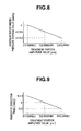
- Fig. 8 is an explanatory diagram for explaining a relationship of the treatment portion amplitude value and a vascular withstanding pressure average value.
- the vascular withstanding pressure average value is about d ⁇ 0.6 [mmHg].
- the vascular withstanding pressure average value is about d[mmHg].
- the vascular withstanding pressure average value is about d ⁇ 0.3 [mmHg].
- the vascular withstanding pressure ability is reduced by about 70%.
- Fig. 9 is an explanatory view for explaining a relationship of the treatment portion amplitude value and the number of dissection times.
- the number of dissection times is N.
- the number of dissection times is 2N which is twice as compared with the dissection times when the amplitude value is the central value.
- the amplitude value of the treatment portion 2e is D 3 which is larger than the central value, the number of dissection times becomes 2/N which is 1/2 times as compared with the dissection times when the amplitude value is the central value.
- the number of dissection times decreases. This is because when the amplitude value of the treatment portion 2e increases, the Teflon pad of the treatment portion 2e easily wears. When the Teflon pad of the treatment portion 2e reaches a failure mode in which the Teflon pad is worn, the ultrasound probe 2d and the movable piece are in contact with each other, and a crack occurs to the ultrasound probe 2d.
- the load on the treatment portion 2e is around the central value.
- the value of the resistor R1 of the ultrasound transducer 2f does not vary, and the current I 2 which is diverted to the non-inductive resistor R2 and the current I 1 which flows into the resistor R1 do not vary. Since the current I 1 which flows into the resistor R1 does not vary like this, the amplitude value of the treatment portion 2e does not vary.
- the load on the treatment portion 2e becomes small. This case is equivalent to the value of the resistor R1 of the ultrasound transducer 2f becoming small, and the current I 2 which is diverted to the non-inductive resistor R2 decreases, whereas the current I 1 which flows to the resistor R1 increases.
- the amplitude value of the treatment portion 2e When the amplitude value of the treatment portion 2e is lower than a value around the central value, the problem of reducing the dissection speed arises. However, when the amplitude value of the treatment portion 2e is lower than the value around the central value like this, the current I 1 which flows into the resistor R1 increases, and therefore, the amplitude value of the treatment portion 2e increases, and reduction in the dissection speed can be suppressed.
- the load on the treatment portion 2e becomes large. This case is equivalent to the value of the resistor R1 of the ultrasound transducer 2f becoming large, and the current I 2 which is diverted to the non-inductive resistor R2 increases, whereas the current I 1 which flows into the resistor R1 decreases.
- the amplitude value of the treatment portion 2e When the amplitude value of the treatment portion 2e is higher than a value around the central value, there arise the problems of reduction in a vascular withstanding pressure ability, promotion of wear of the Teflon pad and increases in stress of the ultrasound probe.
- the amplitude value of the treatment portion 2e when the amplitude value of the treatment portion 2e is higher than a value around the central value like this, the current I 1 which flows into the resistor R1 decreases. Therefore, the amplitude value of the treatment portion 2e decreases, reduction in the vascular withstanding pressure ability, promotion of wear of the Teflon pad and increase in stress of the ultrasound probe can be suppressed.
- the load on the treatment portion 2e is around the central value.
- the value of the resistor R1 of the ultrasound transducer 2f does not vary, and the current I 2 which is diverted to the non-inductive resistor R2 and the current I 1 which flows into the resistor R1 do not vary. Accordingly, the current I 1 which flows into the resistor R1 does not vary, and therefore, the amplitude value of the treatment portion 2e does not vary.
- the load on the treatment portion 2e becomes small. This case is equivalent to the value of the resistor R1 of the ultrasound transducer 2f becoming small, and the current I 2 which is diverted to the non-inductive resistor R2 decreases, whereas the current I 1 which flows into the resistor R1 increases.
- the load on the treatment portion 2e becomes large. This case is equivalent to the value of the resistor R1 of the ultrasound transducer 2f becoming large, the current I 2 which is diverted into the non-inductive resistor R2 increases, whereas the current I 1 which flows into the resistor R1 decreases.
- the load on the treatment portion 2e becomes a value around the central value.
- the value of the resistor R1 of the ultrasound transducer 2f does not vary, and the current I 2 which is diverted to the non-inductive resistor R2 and the current I 1 which flows into the resistor R1 do not vary. Accordingly, the current I 1 which flows into the resistor R1 does not vary, and therefore, the amplitude value of the treatment portion 2e does not vary.
- the load on the treatment portion 2e becomes small. This case is equivalent to decrease in the value of the resistor R1 of the ultrasound transducer 2f, and the current I 2 which is diverted to the non-inductive resistor R2 decreases, whereas the current I 1 which flows into the resistor R1 increases.
- the site to be treated is a thin tissue such as a mesenterium
- the dissection speed is reduced.
- the current I 1 which flows into the resistor R1 increases, the amplitude value of the treatment portion 2e increases, and reduction in the dissection speed can be suppressed.
- the load on the treatment portion 2e becomes large. This case is equivalent to increase in the value of the resistor R1 of the ultrasound transducer 2f, and the current I 2 which is diverted to the non-inductive resistor R2 increases, whereas the current I 1 which flows into the resistor R1 decreases.
- the main apparatus 3 cannot output ultrasound since the stress increase and the load of the ultrasound probe are large.
- the current I 1 which flows into the resistor R1 decreases, the amplitude value of the treatment portion 2e decreases, and inability of the main apparatus 3 to output ultrasound due to large stress increase and load of the ultrasound probe can be suppressed.
- the non-inductive resistor R2 is provided in parallel between the output transformer Tr of the main apparatus 3 and the ultrasound transducer 2f in the hand piece 2, whereby the current which is supplied to the ultrasound transducer 2f from the main apparatus 3 is diverted.
- the current which flows into the non-inductive resistor R2 increases, and the current which flows into the ultrasound transducer 2f decreases.
- the load on the treatment portion 2e becomes small, the current which flows into the non-inductive resistor R2 decreases, and the current which flows into the ultrasound transducer 2f increases.
- the ultrasound operation system 1 decreases the amplitude value of the treatment portion 2e, whereas when the load on the treatment portion 2e becomes small, the ultrasound operation system 1 can increase the amplitude value of the treatment portion 2e. More specifically, even when the load on the treatment portion 2e varies, the ultrasound operation system 1 can control the amplitude value of the treatment portion 2e so that the amplitude value is close to the central value.
- the ultrasound operation system 1 diverts the current which is outputted from the output transformer Tr, and can increase or decrease the current which flows into the ultrasound transducer 2f in accordance to the load on the treatment portion 2e, by the non-inductive resistor R2 provided in the hand piece 2. Whereby, the ultrasound operation system 1 can automatically regulate the amplitude value in accordance with the load on the treatment portion 2e.
- the ultrasound operation system 1 of the present embodiment does not need to provide a control program and a control section for feedback in the main apparatus, does not need to feed back impedance from the ultrasound transducer, and perform feedback control of controlling the current which flows into the ultrasound transducer.
- the current which flows into the ultrasound transducer can be controlled without the need for the control program and the control section for performing feedback control.
Abstract
Description
- The present invention relates to an ultrasound operation system and a surgical treatment instrument, and particularly relates to an ultrasound operation system and a surgical treatment instrument which perform amplitude regulation of an ultrasound transducer.
- Conventionally, as an ultrasound operation system for a surgical operation which applies ultrasound vibration, an ultrasound operation system has been developed, which dissects or coagulates a living tissue by using an ultrasound probe which is ultrasound-vibrated. Ultrasound vibration in the ultrasound operation system is provided by driving control of an ultrasound transducer incorporated in a hand piece, and a distal end portion of the ultrasound probe vibrates with predetermined amplitude.
- However, a value of the amplitude varies depending on a component variation or an assembly variation of an ultrasound transducer, or a component variation or an assembly variation of an ultrasound probe. There is such a problem that, when the value of the amplitude is large, stress of the ultrasound probe increases. Suppressing such a component variation or an assembly variation of the ultrasound transducer, or a variation of components themselves of the ultrasound probe or an assembly variation of the ultrasound probe will lead to an increase in cost.
- Further, when a hand piece is in a shape of scissors, a grasping force amount of a handle varies depending on a component variation or an assembly variation. There are such problems that, when the grasping force amount is small, a dissection speed decreases, and when the grasping force amount is large, wear promotion of a Teflon pad and stress of the ultrasound probe increase. Suppressing such a variation of a component itself which is related to the grasping force or an assembly variation will lead to an increase in cost. In addition, also in the case where the hand piece is in a shape of scissors, the value of the amplitude varies depending on the above-described component variation or the assembly variation of the ultrasound transducer, or the component variation or the assembly variation of the ultrasound probe. There are such problems that, when the value of the amplitude is small, a dissection speed decreases, and when the value of the amplitude is large, the vascular withstanding pressure ability is reduced and wear promotion of a Teflon pad increases.
- Furthermore, a hardness of a site to be treated which a surgeon treats differs in accordance with a site. There are such problems that, when the site to be treated is a thin tissue, a dissection speed decreases, whereas when the site to be treated is a hard tissue, the stress of an ultrasound probe increases and main apparatus cannot output ultrasound in some cases. In view of usability, it is not preferable that the surgeon can treat only a specific site to be treated, that is, an ordinary tissue.
- Therefore, for example, Japanese Patent Application Laid-Open Publication No.
2005-27907 - However, since the ultrasound operation system proposed in the above-described Japanese Patent Application Laid-Open Publication No.
2005-27907 - Therefore, an object of the present invention is to provide an ultrasound operation system capable of controlling an electric current flowing into an ultrasound transducer without a need for providing a control program and a control section for performing feedback control.
- According to one aspect of the present invention, it is possible to provide an ultrasound operation system which includes a drive current generating portion, a surgical treatment instrument including an object to be driven including an ultrasound transducer which is driven by the drive current generating portion, and a treatment portion which is connected to the ultrasound transducer to perform treatment of a living tissue by an ultrasound vibration generated in the ultrasound transducer, and an amplitude regulating portion which is provided between the drive current generating portion and the object to be driven, and performs regulation of an amplitude of the ultrasound transducer by diverting a current which flows into the object to be driven from the drive current generating portion in accordance with a state of a load exerted on the treatment portion and regulating an amount of a current which flows into the object to be driven.
- Further, according to another aspect of the present invention, it is possible to provide a surgical treatment instrument which includes an object to be driven including an ultrasound transducer, and an amplitude regulating portion which is provided in parallel with the object to be driven, diverts a current which flows into the object to be driven and is for driving the object to be driven, and performs regulation of an amplitude of the ultrasound transducer.
-
- [
Fig. 1] Fig. 1 is a view showing a configuration of an ultrasound operation system according to an embodiment of the present invention. - [
Fig. 2] Fig. 2 is a diagram showing an equalizing circuit of the ultrasound operation system before ultrasound output of the present embodiment. - [
Fig. 3] Fig. 3 is a diagram showing the equalizing circuit of the ultrasound operation system during ultrasound output of the present embodiment. - [
Fig. 4] Fig. 4 is an explanatory diagram for explaining a relationship of a non-inductive resistance value and a current which is supplied to an ultrasound transducer. - [
Fig. 5] Fig. 5 is an explanatory diagram for explaining a relationship of a load on a treatment portion and a current which is supplied to the ultrasound transducer. - [
Fig. 6] Fig. 6 is an explanatory diagram for explaining a relationship of the treatment portion amplitude value and an oscillation efficiency of a main apparatus. - [
Fig. 7] Fig. 7 is an explanatory diagram for explaining a relationship of the treatment portion amplitude value and a dissection time. - [
Fig. 8] Fig. 8 is an explanatory diagram for explaining a relationship of the treatment portion amplitude value and a vascular withstanding pressure average value. - [
Fig. 9] Fig. 9 is an explanatory diagram for explaining a relationship of the treatment portion amplitude value and a number of dissection times. - [
Fig. 10] Fig. 10 is a diagram showing an equalizing circuit of a conventional ultrasound operation system. -
Fig. 1 is a view showing a configuration of an ultrasound operation system according to an embodiment of the present invention. Anultrasound operation system 1 is configured by including ahand piece 2, amain apparatus 3 that is an output control apparatus, and a foot switch 4. - The
hand piece 2 is a surgical treatment instrument capable of outputting ultrasound. Thehand piece 2 is connected to themain apparatus 3 via acable 2a which is attachable and detachable. Thehand piece 2 has aninsertion portion 2b and a handle portion 2c. Further, thehand piece 2 contains an object to be driven including anultrasound transducer 2f. Theultrasound transducer 2f has a vibration block which is configured into a cylindrical shape in such a manner that a plurality of piezoelectric elements each formed into a donut shape are stacked to sandwich a plurality of annular electrodes which are disposed between adjacent piezoelectric elements. Further, a bolt is penetrated through through-holes in centers of the piezoelectric elements and the electrodes which are stacked, and the bolt is screwed into a horn portion, whereby theultrasound transducer 2f is configured so that the piezoelectric elements and the electrodes are firmly brought into close contact with one another. Theultrasound transducer 2f is a unit of a Langevin type bolted ultrasound transducer. - Furthermore, the
hand piece 2 has anultrasound probe 2d, and at a distal end side of theultrasound probe 2d, atreatment portion 2e is formed by a distal end portion of theultrasound probe 2d and a movable piece which is openable and closable with respect to the distal end portion. - The
main apparatus 3 supplies a drive signal for ultrasound output to theultrasound transducer 2f contained in thehand piece 2. Theultrasound transducer 2f ultrasound-vibrates by being supplied with the drive signal. The ultrasound vibration is transmitted to the distal end portion of theultrasound probe 2d via theultrasound probe 2d in theinsertion portion 2b. Thehand piece 2 can generate a friction heat in a living tissue of an object to be treated, and can perform treatment such as coagulation, dissection, and the like. - The foot switch 4 is connected to the
main apparatus 3 via acable 4a. The foot switch 4 is a switch for turning on or off ultrasound output at the time of ultrasound output. - A surgeon pulls a wire (not illustrated) which is inserted in the
insertion portion 2b by putting a finger on the handle portion 2c and performing an opening and closing operation to open and close a movable piece in thetreatment portion 2e to be able to grasp a living tissue which is the object to be treated. Further, the surgeon can perform, for example, a laparoscopic surgical operation with thehand piece 2 in one hand, and another treatment instrument in the other hand. - Here, an equalizing circuit of a conventional ultrasound operation system will be described.
Fig. 10 is a diagram showing the equalizing circuit of the conventional ultrasound operation system. - As shown in
Fig. 10 , anultrasound transducer 104 provided in ahand piece 102 of anultrasound operation system 101 is configured by a series resonance circuit in which a resistor R1, a capacitor C1 and a coil L1 are connected in series, and a capacitor C2 connected in parallel to the series circuit. - A
main apparatus 103 of theultrasound operation system 101 is configured by an output transformer Tr, and a coil L2 which is connected to the output transformer Tr in parallel. A signal which is oscillated by an oscillation circuit not illustrated is supplied to a primary winding of the output transformer Tr, and a drive signal for ultrasound output is generated in a secondary winding of the output transformer Tr. - The coil L2 is a coil for performing matching of impedance for the drive signal so as to be able to supply the drive signal efficiently to the
ultrasound transducer 104. A current I1 which is generated in the output transformer Tr, and a current I1+I' which is a total of the current I1 which is generated in the output transformer Tr and a reactive current I' which is generated in the coil L2 is supplied to thehand piece 102 via theaforementioned cable 2a. - Of the current I1+I' which is supplied to the
hand piece 102, the reactive current I' is diverted to the capacitor C2, and the current I1 is supplied to the series resonance circuit configured by the resistor R1, the capacitor C1 and the coil L1. In this manner, the current I1 which is generated in the output transformer Tr is supplied to the series resonance circuit. The series resonance circuit resonates in accordance with the value of the current I1, and theultrasound transducer 104 ultrasound-vibrates. - The conventional
ultrasound operation system 101 cannot regulate the current I1 which is generated in the output transformer Tr. Therefore, an amplitude value of a treatment portion varies depending on a component variation or an assembly variation of theultrasound transducer 104, or a component variation or an assembly variation of the ultrasound probe. Further, in order to regulate the current I1 which is generated in the output transformer Tr, the impedance at a drive time of theultrasound transducer 104 needs to be sensed and fed back to the main apparatus, and a control program and a control section for performing feedback control need to be provided in the main apparatus. -
Fig. 2 is a diagram showing an equalizing circuit of the ultrasound operation system before ultrasound output of the present embodiment. InFig. 2 , the same components as inFig. 10 are assigned with the same reference numerals and characters, and the description thereof will be omitted. - As shown in
Fig. 2 , theultrasound operation system 1 is provided with a non-inductive resistor R2 in parallel between the output transformer Tr and theultrasound transducer 2f. The non-inductive resistor R2 as an amplitude regulating portion diverts a current which is supplied to theultrasound transducer 2f from the output transformer Tr as a drive current generating portion. Further, the non-inductive resistor R2 is provided at thehand piece 2 side, and the value of the non-inductive resistor R2 is the value substantially the same as a value of the resistor R1. The non-inductive resistor R2 as the amplitude regulating portion is provided at thehand piece 2 side, but may be provided at themain apparatus 3 side. Further, the amplitude regulating portion may be a resistor instead of the non-inductive resistor R2. - A value of a current I3 of the output transformer Tr is determined so that when a current I2 is diverted to the non-inductive resistor R2, the current I1 flows into the
ultrasound transducer 2f. More specifically, the value of the current I3 is a value which is obtained by addition of a value of the current I1 and a value of the current I2. Whereby, the series resonance circuit resonates in accordance with the value of the current I1, and theultrasound transducer 2f ultrasound-vibrates. -
Fig. 3 is a diagram showing an equalizing circuit of the ultrasound operation system during ultrasound output of the present embodiment. - In the
ultrasound operation system 1, the capacitor C1 and the coil L2, and the capacitor C2 and the coil L2 cancel out each other in the resonating state during ultrasound output. Accordingly, the equalizing circuit of theultrasound operation system 1 has only the non-inductive resistor R2 and the resistor R1 of theultrasound transducer 2f. The current I1 which flows into the resistor R1 is converted into ultrasound vibration, and a distal end portion of theultrasound probe 2d vibrates with a predetermined amplitude value. - Here, the current I1 which is supplied to the
ultrasound transducer 2f will be described with use ofFigs. 4 and 5 . -
Fig. 4 is an explanatory diagram for explaining a relationship of the non-inductive resistance value and the current which is supplied to the ultrasound transducer. - As shown in
Fig. 4 , when the value of the non-inductive resistor R2 increases to a×7[Ω] from a[Ω], the value of the current I1 which is supplied to the resistor R1 of theultrasound transducer 2f increases to I12[A] from I11[A]. This is because the current I2 which is diverted to the non-inductive resistor R2 decreases as the value of the non-inductive resistor R2 becomes larger. More specifically, when the value of the non-inductive resistor R2 is large, the current I2 which is diverted to the non-inductive resistor R2 decreases, and therefore, the current I1 which flows into the resistor R1 of theultrasound transducer 2f increases. Meanwhile, when the value of the non-inductive resistor R2 is small, the current I2 which is diverted to the non-inductive resistor R2 increases, and therefore, the current I1 which flows into the resistor R1 of theultrasound transducer 2f decreases. -
Fig. 5 is an explanatory diagram for explaining a relationship of a load on the treatment portion and a current which is supplied to the ultrasound transducer. In an example ofFig. 5 , the non-inductive resistor R2 is fixed to a predetermined value, and the load (voltage) on thetreatment portion 2e is changed. The load on thetreatment portion 2e is equivalent to the load on theultrasound transducer 2f. More specifically, increase in the load on thetreatment portion 2e is equivalent to increase in the value of the resistor R1 of theultrasound transducer 2f, and decrease in a load on thetreatment portion 2e is equivalent to decrease in the value of the resistor R1 of theultrasound transducer 2f. - As shown in
Fig. 5 , when the load on thetreatment portion 2e increases to bx2[V] from b[V], the value of the current I1 which is supplied to the resistor R1 of theultrasound transducer 2f decreases to I14[A] from I13[A]. This is because the value of the resistor R1 becomes larger as the load on thetreatment portion 2e becomes larger, and the current I1 which is diverted to the resistor R1 decreases. - As above, when the non-inductive resistor R2 is fixed to the predetermined value, the current which flows into the
ultrasound transducer 2f is regulated in accordance with the load on thetreatment portion 2e, and the amplitude value of theultrasound transducer 2f can be regulated. - Here, the technical problem during treatment will be described with use of
Figs. 6 to 9 . -
Fig. 6 is an explanatory diagram for explaining a relationship of the treatment portion amplitude value and the oscillation efficiency of the main apparatus. - When the amplitude value of the
treatment portion 2e is A2 which is a target (hereinafter, also called a central value), the oscillation efficiency of themain apparatus 3 is c×0.8[%]. When the amplitude value of thetreatment portion 2e is A1 which is smaller than the central value, the oscillation efficiency of themain apparatus 3 is c[%]. When the amplitude value of thetreatment portion 2e is A3 which is larger than the central value, the oscillation efficiency of themain apparatus 3 is c×0.6[%]. - As above, when the amplitude value of the
treatment portion 2e changes by about several tens µm from A1 to A3, the oscillation efficiency of themain apparatus 3 is reduced by about 40%. When the amplitude value of thetreatment portion 2e becomes large, the oscillation efficiency of themain apparatus 3 is reduced. When the amplitude value of thetreatment portion 2e further becomes larger to be an amplitude value outside a certain specified range, the oscillation efficiency of themain apparatus 3 is further reduced and ultrasound output cannot be performed. -
Fig. 7 is an explanatory diagram for explaining a relationship of the amplitude value of the treatment portion and a dissection time. The dissection time ofFig. 7 is a time which is taken when a certain tissue is dissected by 20 cm. - As shown in
Fig. 7 , when the amplitude value of thetreatment portion 2e is B2 which is a central value, the dissection time is T[S]. When the amplitude value of thetreatment portion 2e is B1 which is smaller than the central value, the dissection time is Tx2.5[S] which is about 2.5 times as large as T[S]. When the amplitude value of thetreatment portion 2e is B3 which is larger than the central value, the dissection time is T/2[S] which is about 1/2 of T[S]. - As above, when the amplitude value of the
treatment portion 2e decreases, the dissection speed decreases, and the treatment time becomes long. Meanwhile, when the amplitude value of thetreatment portion 2e is large, the dissection speed increases, but the stress of the ultrasound probe increases. -
Fig. 8 is an explanatory diagram for explaining a relationship of the treatment portion amplitude value and a vascular withstanding pressure average value. - When the amplitude value of the
treatment portion 2e is C2 which is a central value, the vascular withstanding pressure average value is about d×0.6 [mmHg]. When the amplitude value of thetreatment portion 2e is C1 which is smaller than the central value, the vascular withstanding pressure average value is about d[mmHg]. When the amplitude value of thetreatment portion 2e is C3 which is larger than the central value, the vascular withstanding pressure average value is about d×0.3 [mmHg]. - As above, when the amplitude value of the
treatment portion 2e increases, the vascular withstanding pressure ability is reduced by about 70%. -
Fig. 9 is an explanatory view for explaining a relationship of the treatment portion amplitude value and the number of dissection times. - As shown in
Fig. 9 , when the amplitude value of thetreatment portion 2e is D2 which is a central value, the number of dissection times is N. When the amplitude value of thetreatment portion 2e is D1 which is smaller than the central value, the number of dissection times is 2N which is twice as compared with the dissection times when the amplitude value is the central value. When the amplitude value of thetreatment portion 2e is D3 which is larger than the central value, the number of dissection times becomes 2/N which is 1/2 times as compared with the dissection times when the amplitude value is the central value. - As above, when the amplitude value of the
treatment portion 2e increases, the number of dissection times decreases. This is because when the amplitude value of thetreatment portion 2e increases, the Teflon pad of thetreatment portion 2e easily wears. When the Teflon pad of thetreatment portion 2e reaches a failure mode in which the Teflon pad is worn, theultrasound probe 2d and the movable piece are in contact with each other, and a crack occurs to theultrasound probe 2d. - Here, control of the amplitude value of the
treatment portion 2e in the case of the amplitude value of thetreatment portion 2e varying due to a component variation or the like of theultrasound transducer 2f or the like will be described. - When the amplitude value of the
treatment portion 2e is around the central value, the load on thetreatment portion 2e is around the central value. In this case, the value of the resistor R1 of theultrasound transducer 2f does not vary, and the current I2 which is diverted to the non-inductive resistor R2 and the current I1 which flows into the resistor R1 do not vary. Since the current I1 which flows into the resistor R1 does not vary like this, the amplitude value of thetreatment portion 2e does not vary. - When the amplitude value of the
treatment portion 2e is lower than a value around the central value, the load on thetreatment portion 2e becomes small. This case is equivalent to the value of the resistor R1 of theultrasound transducer 2f becoming small, and the current I2 which is diverted to the non-inductive resistor R2 decreases, whereas the current I1 which flows to the resistor R1 increases. - When the amplitude value of the
treatment portion 2e is lower than a value around the central value, the problem of reducing the dissection speed arises. However, when the amplitude value of thetreatment portion 2e is lower than the value around the central value like this, the current I1 which flows into the resistor R1 increases, and therefore, the amplitude value of thetreatment portion 2e increases, and reduction in the dissection speed can be suppressed. - When the amplitude value of the
treatment portion 2e is higher than a value around the central value, the load on thetreatment portion 2e becomes large. This case is equivalent to the value of the resistor R1 of theultrasound transducer 2f becoming large, and the current I2 which is diverted to the non-inductive resistor R2 increases, whereas the current I1 which flows into the resistor R1 decreases. - When the amplitude value of the
treatment portion 2e is higher than a value around the central value, there arise the problems of reduction in a vascular withstanding pressure ability, promotion of wear of the Teflon pad and increases in stress of the ultrasound probe. However, when the amplitude value of thetreatment portion 2e is higher than a value around the central value like this, the current I1 which flows into the resistor R1 decreases. Therefore, the amplitude value of thetreatment portion 2e decreases, reduction in the vascular withstanding pressure ability, promotion of wear of the Teflon pad and increase in stress of the ultrasound probe can be suppressed. - Next, control of the amplitude value of the
treatment portion 2e in the case in which the grasping force amount of the handle 2c varies due to a component variation or the like of the handle 2c will be described. - When the grasping force amount is around the central value, the load on the
treatment portion 2e is around the central value. In this case, the value of the resistor R1 of theultrasound transducer 2f does not vary, and the current I2 which is diverted to the non-inductive resistor R2 and the current I1 which flows into the resistor R1 do not vary. Accordingly, the current I1 which flows into the resistor R1 does not vary, and therefore, the amplitude value of thetreatment portion 2e does not vary. - When the grasping force amount is lower than a value around the central value, the load on the
treatment portion 2e becomes small. This case is equivalent to the value of the resistor R1 of theultrasound transducer 2f becoming small, and the current I2 which is diverted to the non-inductive resistor R2 decreases, whereas the current I1 which flows into the resistor R1 increases. - When the grasping force amount is lower than a value around the central value, there arises the problem of reducing the dissection speed. However, since when the grasping force amount is lower than a value around the central value, the current I1 which flows into the resistor R1 increases, the amplitude value of the
treatment portion 2e increases, and reduction in the dissection speed can be suppressed. - When the grasping force amount is higher than a value around the central value, the load on the
treatment portion 2e becomes large. This case is equivalent to the value of the resistor R1 of theultrasound transducer 2f becoming large, the current I2 which is diverted into the non-inductive resistor R2 increases, whereas the current I1 which flows into the resistor R1 decreases. - When the grasping force amount is higher than a value around the central value, there arise the problems of promotion of wear of the Teflon pad, and increase in stress of the ultrasound probe. However, since when the grasping force amount is higher than a value around the central value like this, the current I1 which flows into the resistor R1 decreases, the amplitude value of the
treatment portion 2e decreases, and promotion of the wear of the Teflon pad and increase in stress of the ultrasound probe can be suppressed. - Next, control of the amplitude value of the
treatment portion 2e in the case of a hardness of a site to be treated varying will be described. - When the site to be treated is an ordinary tissue such as a vessel, the load on the
treatment portion 2e becomes a value around the central value. In this case, the value of the resistor R1 of theultrasound transducer 2f does not vary, and the current I2 which is diverted to the non-inductive resistor R2 and the current I1 which flows into the resistor R1 do not vary. Accordingly, the current I1 which flows into the resistor R1 does not vary, and therefore, the amplitude value of thetreatment portion 2e does not vary. - When the site to be treated is a thin tissue such as a mesenterium, the load on the
treatment portion 2e becomes small. This case is equivalent to decrease in the value of the resistor R1 of theultrasound transducer 2f, and the current I2 which is diverted to the non-inductive resistor R2 decreases, whereas the current I1 which flows into the resistor R1 increases. - When the site to be treated is a thin tissue such as a mesenterium, there arises the problem that the dissection speed is reduced. However, since when the site to be treated is a thin tissue such as a mesenterium like this, the current I1 which flows into the resistor R1 increases, the amplitude value of the
treatment portion 2e increases, and reduction in the dissection speed can be suppressed. - When the site to be treated is a hard tissue such as a uterine ligament, the load on the
treatment portion 2e becomes large. This case is equivalent to increase in the value of the resistor R1 of theultrasound transducer 2f, and the current I2 which is diverted to the non-inductive resistor R2 increases, whereas the current I1 which flows into the resistor R1 decreases. - When the site to be treated is a hard tissue such as a uterine ligament, there arises the problem that the
main apparatus 3 cannot output ultrasound since the stress increase and the load of the ultrasound probe are large. However, since when the site to be treated is a hard tissue such as a uterine ligament like this, the current I1 which flows into the resistor R1 decreases, the amplitude value of thetreatment portion 2e decreases, and inability of themain apparatus 3 to output ultrasound due to large stress increase and load of the ultrasound probe can be suppressed. - As above, in the
ultrasound operation system 1 of the present embodiment, the non-inductive resistor R2 is provided in parallel between the output transformer Tr of themain apparatus 3 and theultrasound transducer 2f in thehand piece 2, whereby the current which is supplied to theultrasound transducer 2f from themain apparatus 3 is diverted. Whereby, when the load on thetreatment portion 2e becomes large, the current which flows into the non-inductive resistor R2 increases, and the current which flows into theultrasound transducer 2f decreases. Further, when the load on thetreatment portion 2e becomes small, the current which flows into the non-inductive resistor R2 decreases, and the current which flows into theultrasound transducer 2f increases. - As a result, when the load on the
treatment portion 2e becomes large, theultrasound operation system 1 decreases the amplitude value of thetreatment portion 2e, whereas when the load on thetreatment portion 2e becomes small, theultrasound operation system 1 can increase the amplitude value of thetreatment portion 2e. More specifically, even when the load on thetreatment portion 2e varies, theultrasound operation system 1 can control the amplitude value of thetreatment portion 2e so that the amplitude value is close to the central value. - As above, the
ultrasound operation system 1 diverts the current which is outputted from the output transformer Tr, and can increase or decrease the current which flows into theultrasound transducer 2f in accordance to the load on thetreatment portion 2e, by the non-inductive resistor R2 provided in thehand piece 2. Whereby, theultrasound operation system 1 can automatically regulate the amplitude value in accordance with the load on thetreatment portion 2e. - As a result, the
ultrasound operation system 1 of the present embodiment does not need to provide a control program and a control section for feedback in the main apparatus, does not need to feed back impedance from the ultrasound transducer, and perform feedback control of controlling the current which flows into the ultrasound transducer. - Consequently, according to the
ultrasound operation system 1 of the present embodiment, the current which flows into the ultrasound transducer can be controlled without the need for the control program and the control section for performing feedback control. - The present invention is not limited to the aforementioned embodiment, and various changes, modifications and the like can be made within the range without departing from the gist of the present invention.
- The present application is filed claiming the priority of
U.S. Provisional Application No. 61/322,510
Claims (9)
- An ultrasound operation system, comprising:a drive current generating portion;a surgical treatment instrument comprising an object to be driven including an ultrasound transducer which is driven by the drive current generating portion, and a treatment portion which is connected to the ultrasound transducer to perform treatment of a living tissue by an ultrasound vibration generated in the ultrasound transducer; andan amplitude regulating portion which is provided between the drive current generating portion and the object to be driven, and performs regulation of an amplitude of the ultrasound transducer by diverting a current which flows into the object to be driven from the drive current generating portion in accordance with a state of a load exerted on the treatment portion and regulating an amount of a current which flows into the object to be driven.
- The ultrasound operation system according to claim 1,
wherein the amplitude regulating portion is a resistor. - The ultrasound operation system according to claim 2,
wherein the resistor is a non-inductive resistor. - The ultrasound operation system according to claim 2,
wherein the resistor is provided in the device. - The ultrasound operation system according to claim 2,
wherein a value of the resistor is substantially the same as a value of a resistor of the ultrasound transducer which the object to be driven has. - A surgical treatment instrument, comprising:an object to be driven including an ultrasound transducer; andan amplitude regulating portion which is provided in parallel with the object to be driven, diverts a current which flows into the object to be driven and is for driving the object to be driven, and performs regulation of an amplitude of the ultrasound transducer.
- The surgical treatment instrument according to claim 6,
wherein the amplitude regulating portion is a resistor. - The surgical treatment instrument according to claim 7,
wherein the resistor is a non-inductive resistor. - The surgical treatment instrument according to claim 7,
wherein a value of the resistor is substantially the same as a value of a resistor of the ultrasound transducer which the object to be driven has.
Applications Claiming Priority (2)
| Application Number | Priority Date | Filing Date | Title |
|---|---|---|---|
| US32251010P | 2010-04-09 | 2010-04-09 | |
| PCT/JP2011/057357 WO2011125544A1 (en) | 2010-04-09 | 2011-03-25 | Ultrasonic surgery system and surgical treatment tool |
Publications (3)
| Publication Number | Publication Date |
|---|---|
| EP2446847A1 true EP2446847A1 (en) | 2012-05-02 |
| EP2446847A4 EP2446847A4 (en) | 2012-06-13 |
| EP2446847B1 EP2446847B1 (en) | 2016-05-04 |
Family
ID=44762498
Family Applications (1)
| Application Number | Title | Priority Date | Filing Date |
|---|---|---|---|
| EP11765445.9A Active EP2446847B1 (en) | 2010-04-09 | 2011-03-25 | Ultrasonic surgery system |
Country Status (5)
| Country | Link |
|---|---|
| US (1) | US20120029395A1 (en) |
| EP (1) | EP2446847B1 (en) |
| JP (1) | JP4889832B2 (en) |
| CN (1) | CN102481165B (en) |
| WO (1) | WO2011125544A1 (en) |
Families Citing this family (5)
| Publication number | Priority date | Publication date | Assignee | Title |
|---|---|---|---|---|
| EP3011922A4 (en) * | 2013-06-18 | 2017-06-21 | Kim, Eungkook | Power supply device for surgical instrument, using ultrasonic waves |
| PT109563B (en) * | 2016-08-02 | 2020-09-23 | Hovione Farmaciencia Sa | METHOD FOR IMPROVING THE DEVELOPMENT AND VALIDATION OF ANALYTICAL AND SAMPLE PREPARATION METHODS FOR ACCURATE AND REPRODUCTIVE MEASUREMENT OF PARTICLE SIZE |
| CN110116084A (en) * | 2019-05-08 | 2019-08-13 | 河南理工大学 | A kind of ultrasonic surgical blade energy converter |
| AU2021337517A1 (en) | 2020-09-02 | 2023-03-30 | Pulse Biosciences, Inc. | Universal handpiece for electrical treatment applicator |
| CN115005934A (en) * | 2022-03-15 | 2022-09-06 | 厚凯(北京)医疗科技有限公司 | Control method and control device of ultrasonic transducer |
Citations (3)
| Publication number | Priority date | Publication date | Assignee | Title |
|---|---|---|---|---|
| EP0135907A2 (en) * | 1983-09-28 | 1985-04-03 | Siemens Aktiengesellschaft | Circuitry for exciting a piezoelectric oscillator in an ultrasound therapy device |
| US5087850A (en) * | 1989-04-19 | 1992-02-11 | Olympus Optical Co., Ltd. | Ultrasonic transducer apparatus |
| US20050020967A1 (en) * | 2003-07-07 | 2005-01-27 | Olympus Corporation | Ultrasonic surgical system and probe |
Family Cites Families (7)
| Publication number | Priority date | Publication date | Assignee | Title |
|---|---|---|---|---|
| JP2898010B2 (en) * | 1989-04-25 | 1999-05-31 | オリンパス光学工業株式会社 | Ultrasound therapy equipment |
| JP2775479B2 (en) * | 1989-08-16 | 1998-07-16 | 岩崎通信機株式会社 | Piezoelectric receiver circuit |
| US5911719A (en) * | 1997-06-05 | 1999-06-15 | Eggers; Philip E. | Resistively heating cutting and coagulating surgical instrument |
| JP2000060866A (en) * | 1998-08-20 | 2000-02-29 | Sumitomo Bakelite Co Ltd | Ultrasonic treatment instrument for surgery |
| US20080058803A1 (en) * | 2006-08-30 | 2008-03-06 | Kenichi Kimura | Surgical instrument and surgical instrument driving method |
| US8512365B2 (en) * | 2007-07-31 | 2013-08-20 | Ethicon Endo-Surgery, Inc. | Surgical instruments |
| US20110146599A1 (en) * | 2009-12-18 | 2011-06-23 | Sciban Stanley J | Hydrogen generating system |
-
2011
- 2011-03-25 CN CN2011800035541A patent/CN102481165B/en active Active
- 2011-03-25 EP EP11765445.9A patent/EP2446847B1/en active Active
- 2011-03-25 WO PCT/JP2011/057357 patent/WO2011125544A1/en active Application Filing
- 2011-03-25 JP JP2011529403A patent/JP4889832B2/en active Active
- 2011-07-25 US US13/189,901 patent/US20120029395A1/en not_active Abandoned
Patent Citations (3)
| Publication number | Priority date | Publication date | Assignee | Title |
|---|---|---|---|---|
| EP0135907A2 (en) * | 1983-09-28 | 1985-04-03 | Siemens Aktiengesellschaft | Circuitry for exciting a piezoelectric oscillator in an ultrasound therapy device |
| US5087850A (en) * | 1989-04-19 | 1992-02-11 | Olympus Optical Co., Ltd. | Ultrasonic transducer apparatus |
| US20050020967A1 (en) * | 2003-07-07 | 2005-01-27 | Olympus Corporation | Ultrasonic surgical system and probe |
Non-Patent Citations (1)
| Title |
|---|
| See also references of WO2011125544A1 * |
Also Published As
| Publication number | Publication date |
|---|---|
| JP4889832B2 (en) | 2012-03-07 |
| CN102481165B (en) | 2013-08-14 |
| US20120029395A1 (en) | 2012-02-02 |
| CN102481165A (en) | 2012-05-30 |
| EP2446847A4 (en) | 2012-06-13 |
| JPWO2011125544A1 (en) | 2013-07-08 |
| WO2011125544A1 (en) | 2011-10-13 |
| EP2446847B1 (en) | 2016-05-04 |
Similar Documents
| Publication | Publication Date | Title |
|---|---|---|
| US10973541B2 (en) | Surgical instrument with variable clamping force | |
| US11826069B2 (en) | Ultrasonic surgical blade | |
| KR102457401B1 (en) | System and method for driving an ultrasonic handpiece as a function of the mechanical impedance of the handpiece | |
| EP2446847B1 (en) | Ultrasonic surgery system | |
| CN107847973B (en) | System and method for driving an ultrasonic handpiece with a linear amplifier | |
| US11737775B2 (en) | Ultrasonic surgical system for osseous transection | |
| AU2015300921A1 (en) | Ultrasonic surgical tool capable of vibrating in plural modes and a drive system that induces non-linear vibrations in the tool tip | |
| EP3340903B1 (en) | Ultrasonic surgical instrument with activation member pair and slidable cover |
Legal Events
| Date | Code | Title | Description |
|---|---|---|---|
| PUAI | Public reference made under article 153(3) epc to a published international application that has entered the european phase |
Free format text: ORIGINAL CODE: 0009012 |
|
| 17P | Request for examination filed |
Effective date: 20120123 |
|
| AK | Designated contracting states |
Kind code of ref document: A1 Designated state(s): AL AT BE BG CH CY CZ DE DK EE ES FI FR GB GR HR HU IE IS IT LI LT LU LV MC MK MT NL NO PL PT RO RS SE SI SK SM TR |
|
| A4 | Supplementary search report drawn up and despatched |
Effective date: 20120510 |
|
| RIC1 | Information provided on ipc code assigned before grant |
Ipc: B06B 1/02 20060101AFI20120504BHEP Ipc: A61B 17/32 20060101ALI20120504BHEP |
|
| DAX | Request for extension of the european patent (deleted) | ||
| RAP1 | Party data changed (applicant data changed or rights of an application transferred) |
Owner name: OLYMPUS CORPORATION |
|
| REG | Reference to a national code |
Ref country code: DE Ref legal event code: R079 Ref document number: 602011026213 Country of ref document: DE Free format text: PREVIOUS MAIN CLASS: A61B0018000000 Ipc: B06B0001020000 |
|
| GRAP | Despatch of communication of intention to grant a patent |
Free format text: ORIGINAL CODE: EPIDOSNIGR1 |
|
| RIC1 | Information provided on ipc code assigned before grant |
Ipc: B06B 1/02 20060101AFI20151029BHEP Ipc: A61B 17/32 20060101ALI20151029BHEP |
|
| INTG | Intention to grant announced |
Effective date: 20151126 |
|
| GRAS | Grant fee paid |
Free format text: ORIGINAL CODE: EPIDOSNIGR3 |
|
| GRAA | (expected) grant |
Free format text: ORIGINAL CODE: 0009210 |
|
| AK | Designated contracting states |
Kind code of ref document: B1 Designated state(s): AL AT BE BG CH CY CZ DE DK EE ES FI FR GB GR HR HU IE IS IT LI LT LU LV MC MK MT NL NO PL PT RO RS SE SI SK SM TR |
|
| REG | Reference to a national code |
Ref country code: GB Ref legal event code: FG4D |
|
| REG | Reference to a national code |
Ref country code: CH Ref legal event code: EP |
|
| REG | Reference to a national code |
Ref country code: AT Ref legal event code: REF Ref document number: 796432 Country of ref document: AT Kind code of ref document: T Effective date: 20160515 |
|
| REG | Reference to a national code |
Ref country code: IE Ref legal event code: FG4D |
|
| REG | Reference to a national code |
Ref country code: DE Ref legal event code: R096 Ref document number: 602011026213 Country of ref document: DE |
|
| REG | Reference to a national code |
Ref country code: NL Ref legal event code: MP Effective date: 20160504 |
|
| REG | Reference to a national code |
Ref country code: LT Ref legal event code: MG4D |
|
| RAP2 | Party data changed (patent owner data changed or rights of a patent transferred) |
Owner name: OLYMPUS CORPORATION |
|
| RAP2 | Party data changed (patent owner data changed or rights of a patent transferred) |
Owner name: OLYMPUS CORPORATION |
|
| PG25 | Lapsed in a contracting state [announced via postgrant information from national office to epo] |
Ref country code: NO Free format text: LAPSE BECAUSE OF FAILURE TO SUBMIT A TRANSLATION OF THE DESCRIPTION OR TO PAY THE FEE WITHIN THE PRESCRIBED TIME-LIMIT Effective date: 20160804 Ref country code: NL Free format text: LAPSE BECAUSE OF FAILURE TO SUBMIT A TRANSLATION OF THE DESCRIPTION OR TO PAY THE FEE WITHIN THE PRESCRIBED TIME-LIMIT Effective date: 20160504 Ref country code: FI Free format text: LAPSE BECAUSE OF FAILURE TO SUBMIT A TRANSLATION OF THE DESCRIPTION OR TO PAY THE FEE WITHIN THE PRESCRIBED TIME-LIMIT Effective date: 20160504 Ref country code: LT Free format text: LAPSE BECAUSE OF FAILURE TO SUBMIT A TRANSLATION OF THE DESCRIPTION OR TO PAY THE FEE WITHIN THE PRESCRIBED TIME-LIMIT Effective date: 20160504 |
|
| RIN2 | Information on inventor provided after grant (corrected) |
Inventor name: SANAI, HIDEO |
|
| REG | Reference to a national code |
Ref country code: AT Ref legal event code: MK05 Ref document number: 796432 Country of ref document: AT Kind code of ref document: T Effective date: 20160504 |
|
| PG25 | Lapsed in a contracting state [announced via postgrant information from national office to epo] |
Ref country code: LV Free format text: LAPSE BECAUSE OF FAILURE TO SUBMIT A TRANSLATION OF THE DESCRIPTION OR TO PAY THE FEE WITHIN THE PRESCRIBED TIME-LIMIT Effective date: 20160504 Ref country code: SE Free format text: LAPSE BECAUSE OF FAILURE TO SUBMIT A TRANSLATION OF THE DESCRIPTION OR TO PAY THE FEE WITHIN THE PRESCRIBED TIME-LIMIT Effective date: 20160504 Ref country code: ES Free format text: LAPSE BECAUSE OF FAILURE TO SUBMIT A TRANSLATION OF THE DESCRIPTION OR TO PAY THE FEE WITHIN THE PRESCRIBED TIME-LIMIT Effective date: 20160504 Ref country code: HR Free format text: LAPSE BECAUSE OF FAILURE TO SUBMIT A TRANSLATION OF THE DESCRIPTION OR TO PAY THE FEE WITHIN THE PRESCRIBED TIME-LIMIT Effective date: 20160504 Ref country code: RS Free format text: LAPSE BECAUSE OF FAILURE TO SUBMIT A TRANSLATION OF THE DESCRIPTION OR TO PAY THE FEE WITHIN THE PRESCRIBED TIME-LIMIT Effective date: 20160504 Ref country code: GR Free format text: LAPSE BECAUSE OF FAILURE TO SUBMIT A TRANSLATION OF THE DESCRIPTION OR TO PAY THE FEE WITHIN THE PRESCRIBED TIME-LIMIT Effective date: 20160805 Ref country code: PT Free format text: LAPSE BECAUSE OF FAILURE TO SUBMIT A TRANSLATION OF THE DESCRIPTION OR TO PAY THE FEE WITHIN THE PRESCRIBED TIME-LIMIT Effective date: 20160905 |
|
| PG25 | Lapsed in a contracting state [announced via postgrant information from national office to epo] |
Ref country code: IT Free format text: LAPSE BECAUSE OF FAILURE TO SUBMIT A TRANSLATION OF THE DESCRIPTION OR TO PAY THE FEE WITHIN THE PRESCRIBED TIME-LIMIT Effective date: 20160504 |
|
| PG25 | Lapsed in a contracting state [announced via postgrant information from national office to epo] |
Ref country code: DK Free format text: LAPSE BECAUSE OF FAILURE TO SUBMIT A TRANSLATION OF THE DESCRIPTION OR TO PAY THE FEE WITHIN THE PRESCRIBED TIME-LIMIT Effective date: 20160504 Ref country code: CZ Free format text: LAPSE BECAUSE OF FAILURE TO SUBMIT A TRANSLATION OF THE DESCRIPTION OR TO PAY THE FEE WITHIN THE PRESCRIBED TIME-LIMIT Effective date: 20160504 Ref country code: RO Free format text: LAPSE BECAUSE OF FAILURE TO SUBMIT A TRANSLATION OF THE DESCRIPTION OR TO PAY THE FEE WITHIN THE PRESCRIBED TIME-LIMIT Effective date: 20160504 Ref country code: EE Free format text: LAPSE BECAUSE OF FAILURE TO SUBMIT A TRANSLATION OF THE DESCRIPTION OR TO PAY THE FEE WITHIN THE PRESCRIBED TIME-LIMIT Effective date: 20160504 Ref country code: SK Free format text: LAPSE BECAUSE OF FAILURE TO SUBMIT A TRANSLATION OF THE DESCRIPTION OR TO PAY THE FEE WITHIN THE PRESCRIBED TIME-LIMIT Effective date: 20160504 |
|
| REG | Reference to a national code |
Ref country code: DE Ref legal event code: R097 Ref document number: 602011026213 Country of ref document: DE |
|
| PG25 | Lapsed in a contracting state [announced via postgrant information from national office to epo] |
Ref country code: BE Free format text: LAPSE BECAUSE OF FAILURE TO SUBMIT A TRANSLATION OF THE DESCRIPTION OR TO PAY THE FEE WITHIN THE PRESCRIBED TIME-LIMIT Effective date: 20160504 Ref country code: AT Free format text: LAPSE BECAUSE OF FAILURE TO SUBMIT A TRANSLATION OF THE DESCRIPTION OR TO PAY THE FEE WITHIN THE PRESCRIBED TIME-LIMIT Effective date: 20160504 Ref country code: PL Free format text: LAPSE BECAUSE OF FAILURE TO SUBMIT A TRANSLATION OF THE DESCRIPTION OR TO PAY THE FEE WITHIN THE PRESCRIBED TIME-LIMIT Effective date: 20160504 Ref country code: SM Free format text: LAPSE BECAUSE OF FAILURE TO SUBMIT A TRANSLATION OF THE DESCRIPTION OR TO PAY THE FEE WITHIN THE PRESCRIBED TIME-LIMIT Effective date: 20160504 |
|
| PLBE | No opposition filed within time limit |
Free format text: ORIGINAL CODE: 0009261 |
|
| STAA | Information on the status of an ep patent application or granted ep patent |
Free format text: STATUS: NO OPPOSITION FILED WITHIN TIME LIMIT |
|
| 26N | No opposition filed |
Effective date: 20170207 |
|
| PG25 | Lapsed in a contracting state [announced via postgrant information from national office to epo] |
Ref country code: SI Free format text: LAPSE BECAUSE OF FAILURE TO SUBMIT A TRANSLATION OF THE DESCRIPTION OR TO PAY THE FEE WITHIN THE PRESCRIBED TIME-LIMIT Effective date: 20160504 |
|
| REG | Reference to a national code |
Ref country code: CH Ref legal event code: PL |
|
| GBPC | Gb: european patent ceased through non-payment of renewal fee |
Effective date: 20170325 |
|
| PG25 | Lapsed in a contracting state [announced via postgrant information from national office to epo] |
Ref country code: MC Free format text: LAPSE BECAUSE OF FAILURE TO SUBMIT A TRANSLATION OF THE DESCRIPTION OR TO PAY THE FEE WITHIN THE PRESCRIBED TIME-LIMIT Effective date: 20160504 |
|
| REG | Reference to a national code |
Ref country code: IE Ref legal event code: MM4A |
|
| REG | Reference to a national code |
Ref country code: FR Ref legal event code: ST Effective date: 20171130 |
|
| PG25 | Lapsed in a contracting state [announced via postgrant information from national office to epo] |
Ref country code: FR Free format text: LAPSE BECAUSE OF NON-PAYMENT OF DUE FEES Effective date: 20170331 Ref country code: LU Free format text: LAPSE BECAUSE OF NON-PAYMENT OF DUE FEES Effective date: 20170325 |
|
| PG25 | Lapsed in a contracting state [announced via postgrant information from national office to epo] |
Ref country code: LI Free format text: LAPSE BECAUSE OF NON-PAYMENT OF DUE FEES Effective date: 20170331 Ref country code: CH Free format text: LAPSE BECAUSE OF NON-PAYMENT OF DUE FEES Effective date: 20170331 Ref country code: IE Free format text: LAPSE BECAUSE OF NON-PAYMENT OF DUE FEES Effective date: 20170325 Ref country code: GB Free format text: LAPSE BECAUSE OF NON-PAYMENT OF DUE FEES Effective date: 20170325 |
|
| PG25 | Lapsed in a contracting state [announced via postgrant information from national office to epo] |
Ref country code: MT Free format text: LAPSE BECAUSE OF NON-PAYMENT OF DUE FEES Effective date: 20170325 |
|
| PG25 | Lapsed in a contracting state [announced via postgrant information from national office to epo] |
Ref country code: AL Free format text: LAPSE BECAUSE OF FAILURE TO SUBMIT A TRANSLATION OF THE DESCRIPTION OR TO PAY THE FEE WITHIN THE PRESCRIBED TIME-LIMIT Effective date: 20160504 |
|
| PG25 | Lapsed in a contracting state [announced via postgrant information from national office to epo] |
Ref country code: HU Free format text: LAPSE BECAUSE OF FAILURE TO SUBMIT A TRANSLATION OF THE DESCRIPTION OR TO PAY THE FEE WITHIN THE PRESCRIBED TIME-LIMIT; INVALID AB INITIO Effective date: 20110325 |
|
| PG25 | Lapsed in a contracting state [announced via postgrant information from national office to epo] |
Ref country code: BG Free format text: LAPSE BECAUSE OF FAILURE TO SUBMIT A TRANSLATION OF THE DESCRIPTION OR TO PAY THE FEE WITHIN THE PRESCRIBED TIME-LIMIT Effective date: 20160504 |
|
| PG25 | Lapsed in a contracting state [announced via postgrant information from national office to epo] |
Ref country code: CY Free format text: LAPSE BECAUSE OF NON-PAYMENT OF DUE FEES Effective date: 20160504 |
|
| PG25 | Lapsed in a contracting state [announced via postgrant information from national office to epo] |
Ref country code: MK Free format text: LAPSE BECAUSE OF FAILURE TO SUBMIT A TRANSLATION OF THE DESCRIPTION OR TO PAY THE FEE WITHIN THE PRESCRIBED TIME-LIMIT Effective date: 20160504 |
|
| PG25 | Lapsed in a contracting state [announced via postgrant information from national office to epo] |
Ref country code: TR Free format text: LAPSE BECAUSE OF FAILURE TO SUBMIT A TRANSLATION OF THE DESCRIPTION OR TO PAY THE FEE WITHIN THE PRESCRIBED TIME-LIMIT Effective date: 20160504 |
|
| PG25 | Lapsed in a contracting state [announced via postgrant information from national office to epo] |
Ref country code: IS Free format text: LAPSE BECAUSE OF FAILURE TO SUBMIT A TRANSLATION OF THE DESCRIPTION OR TO PAY THE FEE WITHIN THE PRESCRIBED TIME-LIMIT Effective date: 20160904 |
|
| PGFP | Annual fee paid to national office [announced via postgrant information from national office to epo] |
Ref country code: DE Payment date: 20230321 Year of fee payment: 13 |
|
| P01 | Opt-out of the competence of the unified patent court (upc) registered |
Effective date: 20230528 |