EP2446827A1 - Providing a body mark in an ultrasound system - Google Patents
Providing a body mark in an ultrasound system Download PDFInfo
- Publication number
- EP2446827A1 EP2446827A1 EP11185412A EP11185412A EP2446827A1 EP 2446827 A1 EP2446827 A1 EP 2446827A1 EP 11185412 A EP11185412 A EP 11185412A EP 11185412 A EP11185412 A EP 11185412A EP 2446827 A1 EP2446827 A1 EP 2446827A1
- Authority
- EP
- European Patent Office
- Prior art keywords
- ultrasound
- body mark
- edge
- ultrasound image
- input information
- Prior art date
- Legal status (The legal status is an assumption and is not a legal conclusion. Google has not performed a legal analysis and makes no representation as to the accuracy of the status listed.)
- Granted
Links
Images


Classifications
-
- A—HUMAN NECESSITIES
- A61—MEDICAL OR VETERINARY SCIENCE; HYGIENE
- A61B—DIAGNOSIS; SURGERY; IDENTIFICATION
- A61B8/00—Diagnosis using ultrasonic, sonic or infrasonic waves
- A61B8/13—Tomography
- A61B8/14—Echotomography
-
- G—PHYSICS
- G01—MEASURING; TESTING
- G01S—RADIO DIRECTION-FINDING; RADIO NAVIGATION; DETERMINING DISTANCE OR VELOCITY BY USE OF RADIO WAVES; LOCATING OR PRESENCE-DETECTING BY USE OF THE REFLECTION OR RERADIATION OF RADIO WAVES; ANALOGOUS ARRANGEMENTS USING OTHER WAVES
- G01S7/00—Details of systems according to groups G01S13/00, G01S15/00, G01S17/00
- G01S7/52—Details of systems according to groups G01S13/00, G01S15/00, G01S17/00 of systems according to group G01S15/00
- G01S7/52017—Details of systems according to groups G01S13/00, G01S15/00, G01S17/00 of systems according to group G01S15/00 particularly adapted to short-range imaging
- G01S7/52053—Display arrangements
- G01S7/52057—Cathode ray tube displays
- G01S7/52073—Production of cursor lines, markers or indicia by electronic means
-
- G—PHYSICS
- G06—COMPUTING OR CALCULATING; COUNTING
- G06V—IMAGE OR VIDEO RECOGNITION OR UNDERSTANDING
- G06V10/00—Arrangements for image or video recognition or understanding
- G06V10/40—Extraction of image or video features
- G06V10/46—Descriptors for shape, contour or point-related descriptors, e.g. scale invariant feature transform [SIFT] or bags of words [BoW]; Salient regional features
Definitions
- the present disclosure generally relates to ultrasound systems, and more particularly to providing a body mark in an ultrasound system.
- An ultrasound system has become an important and popular diagnostic tool since it has a wide range of applications. Specifically, due to its non-invasive and non-destructive nature, the ultrasound system has been extensively used in the medical profession. Modern high-performance ultrasound systems and techniques are commonly used to produce two-dimensional or three-dimensional ultrasound images of internal features of a target object (e.g., human organs).
- a target object e.g., human organs
- the ultrasound system transmits ultrasound signals to a living body, which includes a target object (e.g., a heart, a fetus, etc.), and receives ultrasound signals (i.e., ultrasound echo signals) from the living body to thereby form a 2D (two-dimensional) ultrasound image or a 3D (three-dimensional) ultrasound image.
- a target object e.g., a heart, a fetus, etc.
- ultrasound signals i.e., ultrasound echo signals
- the 2D or 3D ultrasound image is displayed on a display unit.
- the ultrasound system provides the ultrasound image and a body mark, which represents the target object as a picture or icon, to improve the convenience of a user and patient.
- the ultrasound system sets the body mark selected by the user on the ultrasound image.
- the ultrasound system sets the body mark on a part of the ultrasound image.
- a position relationship between the body mark and the ultrasound image may not be provided clearly.
- Embodiments for providing a body mark corresponding to an application on an ultrasound image based on at least one body mark corresponding to at least one body mark in an ultrasound system are disclosed herein.
- an ultrasound system comprises: an ultrasound data acquisition unit configured to acquire ultrasound data corresponding to a living body including a target object; a storage unit for storing at least one body mark corresponding to at least one application; and a processing unit configured to form an ultrasound image based on the ultrasound data, perform edge detection upon the ultrasound image to detect an edge of the target object, detect a body mark corresponding to the edge from the storage unit based on first input information for selecting an application, and set the body mark on the ultrasound image based on the edge.
- a method of providing a body mark comprising: a) acquiring ultrasound data corresponding to a living body including a target object; b) forming an ultrasound image based on the ultrasound data; c) performing edge detection upon the ultrasound image to detect an edge of the target object; d) detecting a body mark corresponding to the edge from a storage unit for storing at least one body mark corresponding to at least one application based on first input information for selecting an application; and e) setting the body mark on the ultrasound image based on the edge.
- the ultrasound system 100 includes an ultrasound data acquisition unit 110.
- the ultrasound data acquisition unit 110 is configured to transmit ultrasound signals to a living body, which includes a target object.
- the target object includes a heart, a fetus and the like.
- the ultrasound data acquisition unit 110 is further configured to receive ultrasound signals (i.e., ultrasound echo signals) from the living body to acquire ultrasound data.
- FIG 2 is a block diagram showing an illustrative embodiment of the ultrasound data acquisition unit.
- the ultrasound data acquisition unit 110 includes an ultrasound probe 210.
- the ultrasound probe 210 includes a plurality of elements (not shown) for reciprocally converting between ultrasound signals and electrical signals.
- the ultrasound probe 210 is configured to transmit ultrasound signals to the living body.
- the ultrasound probe 210 is further configured to receive ultrasound echo signals from the living body to output received signals.
- the received signals are analog signals.
- the ultrasound probe 210 includes a convex probe, a linear probe and the like.
- the ultrasound data acquisition unit 110 further includes a transmitting section 220.
- the transmitting section 220 is configured to control the transmission of the ultrasound signals.
- the transmitting section 220 is further configured to generate electrical signals ("transmitting signals") for obtaining an ultrasound image in consideration of the elements and focal points.
- the ultrasound probe 210 is configured to convert the transmitting signals into the ultrasound signals, transmit the ultrasound signals to the living body and receive the ultrasound echo signals from the living body to thereby output the received signals.
- the ultrasound image includes a brightness mode image. However, it should be noted herein that the ultrasound image may not be limited thereto.
- the transmitting section 220 includes a transmitting signal forming section (not shown), a transmitting delay time information memory (not shown), a transmitting beam former (not shown) and the like.
- the ultrasound data acquisition unit 110 further includes a receiving section 230.
- the receiving section 230 is configured to convert the received signals provided from the ultrasound probe 210 into digital signals.
- the receiving section 230 is further configured to apply delays to the digital signals in consideration of the elements and the focal points to thereby output digital receive-focused signals.
- the receiving section 230 includes an analog-to-digital converter (not shown), a receiving delay time information memory (not shown), a receiving beam former (not shown) and the like.
- the ultrasound data acquisition unit 110 further includes an ultrasound data forming section 240.
- the ultrasound data forming section 240 is configured to form ultrasound data corresponding to the ultrasound image based on the digital receive-focused signals.
- the ultrasound data includes radio frequency data. However, it should be noted herein that the ultrasound data may not be limited thereto.
- the ultrasound data forming section 240 is further configured to perform signal processing (e.g., gain control, etc) upon the digital receive-focused signals.
- the ultrasound system 100 further includes a storage unit 120.
- the storage unit 120 stores at least one body mark corresponding to at least one application.
- the application represents a diagnostic part (i.e., target object) of the living body.
- the body mark includes a template, which represents the diagnostic part.
- the body mark may not be limited thereto.
- the storage unit 120 stores a mapping table for providing a plurality of body marks corresponding to each of the applications (e.g., the heart, the fetus, etc.), as shown in FIG 3 .
- the body marks have different shapes according to a position of the ultrasound probe 210, which is contacted on the surface of the living body. That is, the body marks have different shapes according to a transmitting direction of the ultrasound signals.
- the ultrasound system 100 further includes a user input unit 130.
- the user input unit 130 is configured to receive input information from a user.
- the input information includes first input information for selecting an application.
- the input information further includes second input information for adjusting the body mark.
- the second input information includes information for adjusting a line color, a line style (e.g., a dotted line, a solid line, etc.), a line thickness, a display time (e.g., in seconds), a transparency and a position of the body mark.
- the second input information may not be limited thereto.
- the user input unit 130 includes a control panel, a trackball, a mouse, a keyboard and the like.
- the ultrasound system 100 further includes a processing unit 140 in communication with the ultrasound data acquisition unit 110, the storage unit 120 and the user input unit 130.
- the processing unit 140 includes a central processing unit, a microprocessor, a graphic processing unit and the like.
- FIG 4 is a flow chart showing a process of setting the body mark on the ultrasound image.
- the processing unit 140 is configured to form the ultrasound image based on the ultrasound data provided from the ultrasound data acquisition unit 110, at step S402 in FIG 4 .
- the processing unit 140 is configured to perform edge detection upon the ultrasound image to detect an edge of the target object, at step S404 in FIG 4 .
- the edge is detected by using an edge detecting mask such as a Sobel mask, Prewitt mask, Canny mask and the like. Also, the edge is detected by using a structure tensor.
- the processing unit 140 is configured to retrieve the storage unit 120 to extract at least one body mark corresponding to the input information (i.e., first input information) provided from the user input unit 130, at step S406 in FIG 4 .
- the body marks are extracted in the order stored in the storage unit 120.
- the processing unit 140 is configured to set a body mark corresponding to an application on a predetermined position of the ultrasound image, based on the detected edge and the extracted at least one body mark.
- the processing unit 140 is configured to compare the detected edge with each of the extracted body marks to calculate similarities between the detected edge and each of the extracted body marks, at step S408 in FIG 4 .
- the methods of calculating the similarities are well known in the art. Thus, they have not been described in detail so as not to unnecessarily obscure the present invention.
- the processing unit 140 is configured to the compare the calculated similarities, at step S410 in FIG 4 .
- the processing unit 140 is configured to detect a body mark having a maximum similarity, at step S412 in FIG 4 .
- the processing unit 140 is configured to set the detected body mark on a predetermined position of the ultrasound image, at step S414 in FIG 4 .
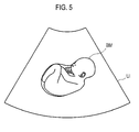
- the processing unit 140 sets the detected body mark BM on the target object of the ultrasound image UI based on the detected edge, as shown in FIG 5 .
- the processing unit 140 is configured to set the extracted body mark on the target object of the ultrasound image based on the detected edge.
- the processing unit 140 is configured to adjust the body mark set on the ultrasound image, based on the input information (i.e., second input information) provided from the user input unit 130. For example, the processing unit 140 adjusts the line color, the line style, the line thickness, the display time, the transparency and the position of the body mark set on the ultrasound image, based on the second input information.
- the input information i.e., second input information
- the processing unit 140 adjusts the line color, the line style, the line thickness, the display time, the transparency and the position of the body mark set on the ultrasound image, based on the second input information.
- the ultrasound system 100 further includes a display unit 150.
- the display unit 150 is configured to display the ultrasound image.
- the display unit 150 is further configured to display the ultrasound image and the body mark.
Landscapes
- Engineering & Computer Science (AREA)
- Health & Medical Sciences (AREA)
- Physics & Mathematics (AREA)
- Life Sciences & Earth Sciences (AREA)
- General Physics & Mathematics (AREA)
- Biomedical Technology (AREA)
- Medical Informatics (AREA)
- Multimedia (AREA)
- Biophysics (AREA)
- Nuclear Medicine, Radiotherapy & Molecular Imaging (AREA)
- Pathology (AREA)
- Radiology & Medical Imaging (AREA)
- Computer Vision & Pattern Recognition (AREA)
- Heart & Thoracic Surgery (AREA)
- Theoretical Computer Science (AREA)
- Molecular Biology (AREA)
- Surgery (AREA)
- Animal Behavior & Ethology (AREA)
- General Health & Medical Sciences (AREA)
- Public Health (AREA)
- Veterinary Medicine (AREA)
- Computer Networks & Wireless Communication (AREA)
- Radar, Positioning & Navigation (AREA)
- Remote Sensing (AREA)
- Ultra Sonic Daignosis Equipment (AREA)
Abstract
Description
- The present application claims priority from Korean Patent Application No.
10-2010-0108249 filed on November 2, 2010 - The present disclosure generally relates to ultrasound systems, and more particularly to providing a body mark in an ultrasound system.
- An ultrasound system has become an important and popular diagnostic tool since it has a wide range of applications. Specifically, due to its non-invasive and non-destructive nature, the ultrasound system has been extensively used in the medical profession. Modern high-performance ultrasound systems and techniques are commonly used to produce two-dimensional or three-dimensional ultrasound images of internal features of a target object (e.g., human organs).
- The ultrasound system transmits ultrasound signals to a living body, which includes a target object (e.g., a heart, a fetus, etc.), and receives ultrasound signals (i.e., ultrasound echo signals) from the living body to thereby form a 2D (two-dimensional) ultrasound image or a 3D (three-dimensional) ultrasound image. The 2D or 3D ultrasound image is displayed on a display unit.
- The ultrasound system provides the ultrasound image and a body mark, which represents the target object as a picture or icon, to improve the convenience of a user and patient. The ultrasound system sets the body mark selected by the user on the ultrasound image. However, there is a problem since a different body mark from the target object may be provided. Also, the ultrasound system sets the body mark on a part of the ultrasound image. However, there is a problem that a position relationship between the body mark and the ultrasound image may not be provided clearly.
- Embodiments for providing a body mark corresponding to an application on an ultrasound image based on at least one body mark corresponding to at least one body mark in an ultrasound system are disclosed herein.
- In one embodiment, by way of non-limiting example, an ultrasound system comprises: an ultrasound data acquisition unit configured to acquire ultrasound data corresponding to a living body including a target object; a storage unit for storing at least one body mark corresponding to at least one application; and a processing unit configured to form an ultrasound image based on the ultrasound data, perform edge detection upon the ultrasound image to detect an edge of the target object, detect a body mark corresponding to the edge from the storage unit based on first input information for selecting an application, and set the body mark on the ultrasound image based on the edge.
- In another embodiment, there is a method of providing a body mark, comprising: a) acquiring ultrasound data corresponding to a living body including a target object; b) forming an ultrasound image based on the ultrasound data; c) performing edge detection upon the ultrasound image to detect an edge of the target object; d) detecting a body mark corresponding to the edge from a storage unit for storing at least one body mark corresponding to at least one application based on first input information for selecting an application; and e) setting the body mark on the ultrasound image based on the edge.
- This summary is provided to introduce a selection of concepts in a simplified form that are further described below in the Detailed Description. This Summary is not intended to identify key or essential features of the claimed subject matter, nor is it intended to be used in determining the scope of the claimed subject matter.
-
-
FIG 1 is a block diagram showing an illustrative embodiment of an ultrasound system. -
FIG 2 is a block diagram showing an illustrative embodiment of an ultrasound data acquisition unit. -
FIG 3 is a schematic diagram showing an example of a mapping table. -
FIG 4 is a flow chart showing a process of setting a body mark on an ultrasound image. -
FIG 5 is a schematic diagram showing an example of an ultrasound image and a body mark. - A detailed description may be provided with reference to the accompanying drawings. One of ordinary skill in the art may realize that the following description is illustrative only and is not in any way limiting.
- Referring to
FIG 1 , anultrasound system 100 in accordance with an illustrative embodiment is shown. As depicted therein, theultrasound system 100 includes an ultrasounddata acquisition unit 110. - The ultrasound
data acquisition unit 110 is configured to transmit ultrasound signals to a living body, which includes a target object. The target object includes a heart, a fetus and the like. The ultrasounddata acquisition unit 110 is further configured to receive ultrasound signals (i.e., ultrasound echo signals) from the living body to acquire ultrasound data. -
FIG 2 is a block diagram showing an illustrative embodiment of the ultrasound data acquisition unit. Referring toFIG 2 , the ultrasounddata acquisition unit 110 includes anultrasound probe 210. - The
ultrasound probe 210 includes a plurality of elements (not shown) for reciprocally converting between ultrasound signals and electrical signals. Theultrasound probe 210 is configured to transmit ultrasound signals to the living body. Theultrasound probe 210 is further configured to receive ultrasound echo signals from the living body to output received signals. The received signals are analog signals. Theultrasound probe 210 includes a convex probe, a linear probe and the like. - The ultrasound
data acquisition unit 110 further includes a transmittingsection 220. The transmittingsection 220 is configured to control the transmission of the ultrasound signals. The transmittingsection 220 is further configured to generate electrical signals ("transmitting signals") for obtaining an ultrasound image in consideration of the elements and focal points. Thus, theultrasound probe 210 is configured to convert the transmitting signals into the ultrasound signals, transmit the ultrasound signals to the living body and receive the ultrasound echo signals from the living body to thereby output the received signals. The ultrasound image includes a brightness mode image. However, it should be noted herein that the ultrasound image may not be limited thereto. The transmittingsection 220 includes a transmitting signal forming section (not shown), a transmitting delay time information memory (not shown), a transmitting beam former (not shown) and the like. - The ultrasound
data acquisition unit 110 further includes areceiving section 230. Thereceiving section 230 is configured to convert the received signals provided from theultrasound probe 210 into digital signals. The receivingsection 230 is further configured to apply delays to the digital signals in consideration of the elements and the focal points to thereby output digital receive-focused signals. Thereceiving section 230 includes an analog-to-digital converter (not shown), a receiving delay time information memory (not shown), a receiving beam former (not shown) and the like. - The ultrasound
data acquisition unit 110 further includes an ultrasounddata forming section 240. The ultrasounddata forming section 240 is configured to form ultrasound data corresponding to the ultrasound image based on the digital receive-focused signals. The ultrasound data includes radio frequency data. However, it should be noted herein that the ultrasound data may not be limited thereto. The ultrasounddata forming section 240 is further configured to perform signal processing (e.g., gain control, etc) upon the digital receive-focused signals. - Referring back to
FIG 1 , theultrasound system 100 further includes astorage unit 120. Thestorage unit 120 stores at least one body mark corresponding to at least one application. The application represents a diagnostic part (i.e., target object) of the living body. The body mark includes a template, which represents the diagnostic part. However, it should be noted herein that the body mark may not be limited thereto. - In one embodiment, the
storage unit 120 stores a mapping table for providing a plurality of body marks corresponding to each of the applications (e.g., the heart, the fetus, etc.), as shown inFIG 3 . The body marks have different shapes according to a position of theultrasound probe 210, which is contacted on the surface of the living body. That is, the body marks have different shapes according to a transmitting direction of the ultrasound signals. - The
ultrasound system 100 further includes auser input unit 130. Theuser input unit 130 is configured to receive input information from a user. In one embodiment, the input information includes first input information for selecting an application. The input information further includes second input information for adjusting the body mark. For example, the second input information includes information for adjusting a line color, a line style (e.g., a dotted line, a solid line, etc.), a line thickness, a display time (e.g., in seconds), a transparency and a position of the body mark. However, it should be noted herein that the second input information may not be limited thereto. Theuser input unit 130 includes a control panel, a trackball, a mouse, a keyboard and the like. - The
ultrasound system 100 further includes aprocessing unit 140 in communication with the ultrasounddata acquisition unit 110, thestorage unit 120 and theuser input unit 130. Theprocessing unit 140 includes a central processing unit, a microprocessor, a graphic processing unit and the like. -
FIG 4 is a flow chart showing a process of setting the body mark on the ultrasound image. Theprocessing unit 140 is configured to form the ultrasound image based on the ultrasound data provided from the ultrasounddata acquisition unit 110, at step S402 inFIG 4 . - The
processing unit 140 is configured to perform edge detection upon the ultrasound image to detect an edge of the target object, at step S404 inFIG 4 . The edge is detected by using an edge detecting mask such as a Sobel mask, Prewitt mask, Canny mask and the like. Also, the edge is detected by using a structure tensor. - The
processing unit 140 is configured to retrieve thestorage unit 120 to extract at least one body mark corresponding to the input information (i.e., first input information) provided from theuser input unit 130, at step S406 inFIG 4 . The body marks are extracted in the order stored in thestorage unit 120. - The
processing unit 140 is configured to set a body mark corresponding to an application on a predetermined position of the ultrasound image, based on the detected edge and the extracted at least one body mark. - More particularly, if at least two body marks are extracted from the
storage unit 120, theprocessing unit 140 is configured to compare the detected edge with each of the extracted body marks to calculate similarities between the detected edge and each of the extracted body marks, at step S408 inFIG 4 . The methods of calculating the similarities are well known in the art. Thus, they have not been described in detail so as not to unnecessarily obscure the present invention. Theprocessing unit 140 is configured to the compare the calculated similarities, at step S410 inFIG 4 . Theprocessing unit 140 is configured to detect a body mark having a maximum similarity, at step S412 inFIG 4 . - The
processing unit 140 is configured to set the detected body mark on a predetermined position of the ultrasound image, at step S414 inFIG 4 . In one embodiment, theprocessing unit 140 sets the detected body mark BM on the target object of the ultrasound image UI based on the detected edge, as shown inFIG 5 . - Otherwise, if one body mark is extracted from the
storage unit 120, theprocessing unit 140 is configured to set the extracted body mark on the target object of the ultrasound image based on the detected edge. - Optionally, the
processing unit 140 is configured to adjust the body mark set on the ultrasound image, based on the input information (i.e., second input information) provided from theuser input unit 130. For example, theprocessing unit 140 adjusts the line color, the line style, the line thickness, the display time, the transparency and the position of the body mark set on the ultrasound image, based on the second input information. - Referring back to
FIG 1 , theultrasound system 100 further includes adisplay unit 150. Thedisplay unit 150 is configured to display the ultrasound image. Thedisplay unit 150 is further configured to display the ultrasound image and the body mark. - Although embodiments have been described with reference to a number of illustrative embodiments thereof, it should be understood that numerous other modifications and embodiments can be devised by those skilled in the art that will fall within the scope of the principles of this disclosure. More particularly, numerous variations and modifications are possible in the component parts and/or arrangements of the subject combination arrangement within the scope of the disclosure, the drawings and the appended claims. In addition to variations and modifications in the component parts and/or arrangements, alternative uses will also be apparent to those skilled in the art.
Claims (10)
- An ultrasound system, comprising:an ultrasound data acquisition unit configured to acquire ultrasound data corresponding to a living body including a target object;a storage unit for storing at least one body mark corresponding to at least one application; anda processing unit configured to form an ultrasound image based on the ultrasound data, perform edge detection upon the ultrasound image to detect an edge of the target object, detect a body mark corresponding to the edge from the storage unit based on first input information for selecting an application, and set the body mark on the ultrasound image based on the edge.
- The ultrasound system of Claim 1, wherein the at least one body mark has different shapes according to a transmitting direction of ultrasound signals.
- The ultrasound system of Claim 1, wherein the processing unit is configured to:extract at least one body mark corresponding to the first input information from the storage unit;calculate at least one similarity between the edge and the extracted body mark; anddetect the body mark having a maximum similarity based on the calculated at least one similarity.
- The ultrasound system of Claim 1, further comprising:a user input unit configured to receive the first input information from a user.
- The ultrasound system of Claim 4, wherein the user input unit is further configured to receive second input information for adjusting the body mark set on the ultrasound image.
- The ultrasound system of Claim 5, wherein the processing unit is further configured to adjust at least one of a line color, a line style, a line thickness, a display time, a transparency and a position of the body mark set on the ultrasound image.
- A method of providing a body mark, comprising:a) acquiring ultrasound data corresponding to a living body including a target obj ect;b) forming an ultrasound image based on the ultrasound data;c) performing edge detection upon the ultrasound image to detect an edge of the target obj ect;d) detecting a body mark corresponding to the edge from a storage unit for storing at least one body mark corresponding to at least one application based on first input information for selecting an application; ande) setting the body mark on the ultrasound image based on the edge.
- The method of Claim 7, wherein the at least one body mark has different shapes according to a transmitting direction of ultrasound signals.
- The method of Claim 7, wherein the step d) comprises:extracting at least one body mark corresponding to the first input information from the storage unit;calculating at least one similarity between the edge and the extracted body mark; anddetecting the body mark having a maximum similarity based on the calculated at least one similarity.
- The method of Claim 7, further comprising:f) adjusting at least one of a line color, a line style, a line thickness, a display time, a transparency and a position of the body mark set on the ultrasound image, based on second input information for adjusting the body mark set on the ultrasound image.
Applications Claiming Priority (1)
| Application Number | Priority Date | Filing Date | Title |
|---|---|---|---|
| KR1020100108249A KR20120046539A (en) | 2010-11-02 | 2010-11-02 | Ultrasound system and method for providing body mark |
Publications (2)
| Publication Number | Publication Date |
|---|---|
| EP2446827A1 true EP2446827A1 (en) | 2012-05-02 |
| EP2446827B1 EP2446827B1 (en) | 2013-05-01 |
Family
ID=44862567
Family Applications (1)
| Application Number | Title | Priority Date | Filing Date |
|---|---|---|---|
| EP11185412.1A Active EP2446827B1 (en) | 2010-11-02 | 2011-10-17 | Providing a body mark in an ultrasound system |
Country Status (3)
| Country | Link |
|---|---|
| US (1) | US20120108962A1 (en) |
| EP (1) | EP2446827B1 (en) |
| KR (1) | KR20120046539A (en) |
Families Citing this family (7)
| Publication number | Priority date | Publication date | Assignee | Title |
|---|---|---|---|---|
| US10667790B2 (en) | 2012-03-26 | 2020-06-02 | Teratech Corporation | Tablet ultrasound system |
| US9877699B2 (en) | 2012-03-26 | 2018-01-30 | Teratech Corporation | Tablet ultrasound system |
| JP2015226607A (en) * | 2014-05-30 | 2015-12-17 | 株式会社東芝 | Ultrasonic diagnostic equipment |
| JP2019534110A (en) | 2016-11-16 | 2019-11-28 | テラテク・コーポレーシヨン | Portable ultrasound system |
| JP7427497B2 (en) * | 2020-03-26 | 2024-02-05 | キヤノン株式会社 | Information processing device, information processing method, program, and ultrasound diagnostic device |
| US12547887B2 (en) * | 2020-04-17 | 2026-02-10 | University Of Utah Research Foundation | System for detecting electric signals |
| CN117426789A (en) * | 2022-07-14 | 2024-01-23 | 深圳迈瑞生物医疗电子股份有限公司 | Automatic body position map matching method and ultrasound imaging system |
Citations (5)
| Publication number | Priority date | Publication date | Assignee | Title |
|---|---|---|---|---|
| EP0501819A2 (en) * | 1991-02-28 | 1992-09-02 | Olympus Optical Co., Ltd. | Ultrasonic diagnostic apparatus |
| EP1623674A1 (en) * | 2003-05-08 | 2006-02-08 | Hitachi Medical Corporation | Reference image display method for ultrasonography and ultrasonograph |
| EP1857051A1 (en) * | 2006-05-09 | 2007-11-21 | Kabushiki Kaisha Toshiba | An ultrasonic imaging apparatus and a method of displaying ultrasonic images |
| KR20100108249A (en) | 2009-03-26 | 2010-10-06 | 가부시키가이샤 한도오따이 에네루기 켄큐쇼 | Liquid crystal display device, driving method of the same, and electronic device including the same |
| EP2314223A1 (en) * | 2008-07-15 | 2011-04-27 | Hitachi Medical Corporation | Ultrasound diagnostic device and method for displaying probe operation guide of the same |
-
2010
- 2010-11-02 KR KR1020100108249A patent/KR20120046539A/en not_active Ceased
-
2011
- 2011-10-17 EP EP11185412.1A patent/EP2446827B1/en active Active
- 2011-10-19 US US13/276,705 patent/US20120108962A1/en not_active Abandoned
Patent Citations (5)
| Publication number | Priority date | Publication date | Assignee | Title |
|---|---|---|---|---|
| EP0501819A2 (en) * | 1991-02-28 | 1992-09-02 | Olympus Optical Co., Ltd. | Ultrasonic diagnostic apparatus |
| EP1623674A1 (en) * | 2003-05-08 | 2006-02-08 | Hitachi Medical Corporation | Reference image display method for ultrasonography and ultrasonograph |
| EP1857051A1 (en) * | 2006-05-09 | 2007-11-21 | Kabushiki Kaisha Toshiba | An ultrasonic imaging apparatus and a method of displaying ultrasonic images |
| EP2314223A1 (en) * | 2008-07-15 | 2011-04-27 | Hitachi Medical Corporation | Ultrasound diagnostic device and method for displaying probe operation guide of the same |
| KR20100108249A (en) | 2009-03-26 | 2010-10-06 | 가부시키가이샤 한도오따이 에네루기 켄큐쇼 | Liquid crystal display device, driving method of the same, and electronic device including the same |
Also Published As
| Publication number | Publication date |
|---|---|
| KR20120046539A (en) | 2012-05-10 |
| US20120108962A1 (en) | 2012-05-03 |
| EP2446827B1 (en) | 2013-05-01 |
Similar Documents
| Publication | Publication Date | Title |
|---|---|---|
| US8900147B2 (en) | Performing image process and size measurement upon a three-dimensional ultrasound image in an ultrasound system | |
| EP2289420B1 (en) | Setting an optimal image parameter in an ultrasound system | |
| EP2444001A1 (en) | Providing an ultrasound spatial compound image based on a phased array probe in an ultrasound system | |
| EP2446827B1 (en) | Providing a body mark in an ultrasound system | |
| US9261485B2 (en) | Providing color doppler image based on qualification curve information in ultrasound system | |
| US8956298B2 (en) | Providing an ultrasound spatial compound image in an ultrasound system | |
| EP2302414A2 (en) | Ultrasound system and method of performing measurement on three-dimensional ultrasound image | |
| US9069062B2 (en) | Surface rendering for volume data in an ultrasound system | |
| EP2610635A2 (en) | Providing Doppler spectrum images corresponding to at least two sample volumes in ultrasound system | |
| EP2333576A2 (en) | Providing a three-dimensional ultrasound image based on a sub region of interest in an ultrasound system | |
| US9151841B2 (en) | Providing an ultrasound spatial compound image based on center lines of ultrasound images in an ultrasound system | |
| US9078590B2 (en) | Providing additional information corresponding to change of blood flow with a time in ultrasound system | |
| US20120190984A1 (en) | Ultrasound system with opacity setting unit | |
| EP2281509B1 (en) | Setting a Sagittal View in an Ultrasound System | |
| US20110028842A1 (en) | Providing A Plurality Of Slice Images In An Ultrasound System | |
| EP2422704A2 (en) | Providing ultrasound spatial compound images in an ultrasound system | |
| EP2386251A1 (en) | Providing at least one slice image with additional information in an ultrasound system | |
| WO2015099835A1 (en) | System and method for displaying ultrasound images | |
| US20120108964A1 (en) | Performing gain control process based on application in ultrasound system | |
| JP5841771B2 (en) | Ultrasonic data processor | |
| KR102096045B1 (en) | Ultrasound system and method for providing depth information of region of interest | |
| EP2336804A2 (en) | Ultrasound system and method for providing doppler sound |
Legal Events
| Date | Code | Title | Description |
|---|---|---|---|
| PUAI | Public reference made under article 153(3) epc to a published international application that has entered the european phase |
Free format text: ORIGINAL CODE: 0009012 |
|
| AK | Designated contracting states |
Kind code of ref document: A1 Designated state(s): AL AT BE BG CH CY CZ DE DK EE ES FI FR GB GR HR HU IE IS IT LI LT LU LV MC MK MT NL NO PL PT RO RS SE SI SK SM TR |
|
| AX | Request for extension of the european patent |
Extension state: BA ME |
|
| GRAP | Despatch of communication of intention to grant a patent |
Free format text: ORIGINAL CODE: EPIDOSNIGR1 |
|
| 17P | Request for examination filed |
Effective date: 20121029 |
|
| RIC1 | Information provided on ipc code assigned before grant |
Ipc: A61B 8/14 20060101AFI20121122BHEP |
|
| GRAS | Grant fee paid |
Free format text: ORIGINAL CODE: EPIDOSNIGR3 |
|
| GRAA | (expected) grant |
Free format text: ORIGINAL CODE: 0009210 |
|
| AK | Designated contracting states |
Kind code of ref document: B1 Designated state(s): AL AT BE BG CH CY CZ DE DK EE ES FI FR GB GR HR HU IE IS IT LI LT LU LV MC MK MT NL NO PL PT RO RS SE SI SK SM TR |
|
| REG | Reference to a national code |
Ref country code: GB Ref legal event code: FG4D |
|
| REG | Reference to a national code |
Ref country code: CH Ref legal event code: EP Ref country code: AT Ref legal event code: REF Ref document number: 609381 Country of ref document: AT Kind code of ref document: T Effective date: 20130515 |
|
| REG | Reference to a national code |
Ref country code: IE Ref legal event code: FG4D |
|
| REG | Reference to a national code |
Ref country code: DE Ref legal event code: R096 Ref document number: 602011001536 Country of ref document: DE Effective date: 20130704 |
|
| REG | Reference to a national code |
Ref country code: NL Ref legal event code: T3 |
|
| REG | Reference to a national code |
Ref country code: AT Ref legal event code: MK05 Ref document number: 609381 Country of ref document: AT Kind code of ref document: T Effective date: 20130501 |
|
| REG | Reference to a national code |
Ref country code: LT Ref legal event code: MG4D |
|
| PG25 | Lapsed in a contracting state [announced via postgrant information from national office to epo] |
Ref country code: FI Free format text: LAPSE BECAUSE OF FAILURE TO SUBMIT A TRANSLATION OF THE DESCRIPTION OR TO PAY THE FEE WITHIN THE PRESCRIBED TIME-LIMIT Effective date: 20130501 Ref country code: AT Free format text: LAPSE BECAUSE OF FAILURE TO SUBMIT A TRANSLATION OF THE DESCRIPTION OR TO PAY THE FEE WITHIN THE PRESCRIBED TIME-LIMIT Effective date: 20130501 Ref country code: IS Free format text: LAPSE BECAUSE OF FAILURE TO SUBMIT A TRANSLATION OF THE DESCRIPTION OR TO PAY THE FEE WITHIN THE PRESCRIBED TIME-LIMIT Effective date: 20130901 Ref country code: LT Free format text: LAPSE BECAUSE OF FAILURE TO SUBMIT A TRANSLATION OF THE DESCRIPTION OR TO PAY THE FEE WITHIN THE PRESCRIBED TIME-LIMIT Effective date: 20130501 Ref country code: ES Free format text: LAPSE BECAUSE OF FAILURE TO SUBMIT A TRANSLATION OF THE DESCRIPTION OR TO PAY THE FEE WITHIN THE PRESCRIBED TIME-LIMIT Effective date: 20130812 Ref country code: SE Free format text: LAPSE BECAUSE OF FAILURE TO SUBMIT A TRANSLATION OF THE DESCRIPTION OR TO PAY THE FEE WITHIN THE PRESCRIBED TIME-LIMIT Effective date: 20130501 Ref country code: NO Free format text: LAPSE BECAUSE OF FAILURE TO SUBMIT A TRANSLATION OF THE DESCRIPTION OR TO PAY THE FEE WITHIN THE PRESCRIBED TIME-LIMIT Effective date: 20130801 Ref country code: PT Free format text: LAPSE BECAUSE OF FAILURE TO SUBMIT A TRANSLATION OF THE DESCRIPTION OR TO PAY THE FEE WITHIN THE PRESCRIBED TIME-LIMIT Effective date: 20130902 Ref country code: GR Free format text: LAPSE BECAUSE OF FAILURE TO SUBMIT A TRANSLATION OF THE DESCRIPTION OR TO PAY THE FEE WITHIN THE PRESCRIBED TIME-LIMIT Effective date: 20130802 Ref country code: SI Free format text: LAPSE BECAUSE OF FAILURE TO SUBMIT A TRANSLATION OF THE DESCRIPTION OR TO PAY THE FEE WITHIN THE PRESCRIBED TIME-LIMIT Effective date: 20130501 |
|
| PG25 | Lapsed in a contracting state [announced via postgrant information from national office to epo] |
Ref country code: BG Free format text: LAPSE BECAUSE OF FAILURE TO SUBMIT A TRANSLATION OF THE DESCRIPTION OR TO PAY THE FEE WITHIN THE PRESCRIBED TIME-LIMIT Effective date: 20130801 Ref country code: HR Free format text: LAPSE BECAUSE OF FAILURE TO SUBMIT A TRANSLATION OF THE DESCRIPTION OR TO PAY THE FEE WITHIN THE PRESCRIBED TIME-LIMIT Effective date: 20130501 Ref country code: RS Free format text: LAPSE BECAUSE OF FAILURE TO SUBMIT A TRANSLATION OF THE DESCRIPTION OR TO PAY THE FEE WITHIN THE PRESCRIBED TIME-LIMIT Effective date: 20130501 Ref country code: CY Free format text: LAPSE BECAUSE OF FAILURE TO SUBMIT A TRANSLATION OF THE DESCRIPTION OR TO PAY THE FEE WITHIN THE PRESCRIBED TIME-LIMIT Effective date: 20130501 Ref country code: PL Free format text: LAPSE BECAUSE OF FAILURE TO SUBMIT A TRANSLATION OF THE DESCRIPTION OR TO PAY THE FEE WITHIN THE PRESCRIBED TIME-LIMIT Effective date: 20130501 |
|
| PG25 | Lapsed in a contracting state [announced via postgrant information from national office to epo] |
Ref country code: LV Free format text: LAPSE BECAUSE OF FAILURE TO SUBMIT A TRANSLATION OF THE DESCRIPTION OR TO PAY THE FEE WITHIN THE PRESCRIBED TIME-LIMIT Effective date: 20130501 |
|
| PG25 | Lapsed in a contracting state [announced via postgrant information from national office to epo] |
Ref country code: BE Free format text: LAPSE BECAUSE OF FAILURE TO SUBMIT A TRANSLATION OF THE DESCRIPTION OR TO PAY THE FEE WITHIN THE PRESCRIBED TIME-LIMIT Effective date: 20130501 Ref country code: SK Free format text: LAPSE BECAUSE OF FAILURE TO SUBMIT A TRANSLATION OF THE DESCRIPTION OR TO PAY THE FEE WITHIN THE PRESCRIBED TIME-LIMIT Effective date: 20130501 Ref country code: EE Free format text: LAPSE BECAUSE OF FAILURE TO SUBMIT A TRANSLATION OF THE DESCRIPTION OR TO PAY THE FEE WITHIN THE PRESCRIBED TIME-LIMIT Effective date: 20130501 Ref country code: DK Free format text: LAPSE BECAUSE OF FAILURE TO SUBMIT A TRANSLATION OF THE DESCRIPTION OR TO PAY THE FEE WITHIN THE PRESCRIBED TIME-LIMIT Effective date: 20130501 Ref country code: CZ Free format text: LAPSE BECAUSE OF FAILURE TO SUBMIT A TRANSLATION OF THE DESCRIPTION OR TO PAY THE FEE WITHIN THE PRESCRIBED TIME-LIMIT Effective date: 20130501 |
|
| PG25 | Lapsed in a contracting state [announced via postgrant information from national office to epo] |
Ref country code: RO Free format text: LAPSE BECAUSE OF FAILURE TO SUBMIT A TRANSLATION OF THE DESCRIPTION OR TO PAY THE FEE WITHIN THE PRESCRIBED TIME-LIMIT Effective date: 20130501 |
|
| PLBE | No opposition filed within time limit |
Free format text: ORIGINAL CODE: 0009261 |
|
| STAA | Information on the status of an ep patent application or granted ep patent |
Free format text: STATUS: NO OPPOSITION FILED WITHIN TIME LIMIT |
|
| 26N | No opposition filed |
Effective date: 20140204 |
|
| REG | Reference to a national code |
Ref country code: DE Ref legal event code: R097 Ref document number: 602011001536 Country of ref document: DE Effective date: 20140204 |
|
| PG25 | Lapsed in a contracting state [announced via postgrant information from national office to epo] |
Ref country code: MC Free format text: LAPSE BECAUSE OF FAILURE TO SUBMIT A TRANSLATION OF THE DESCRIPTION OR TO PAY THE FEE WITHIN THE PRESCRIBED TIME-LIMIT Effective date: 20130501 |
|
| REG | Reference to a national code |
Ref country code: IE Ref legal event code: MM4A |
|
| PG25 | Lapsed in a contracting state [announced via postgrant information from national office to epo] |
Ref country code: IE Free format text: LAPSE BECAUSE OF NON-PAYMENT OF DUE FEES Effective date: 20131017 |
|
| PG25 | Lapsed in a contracting state [announced via postgrant information from national office to epo] |
Ref country code: SM Free format text: LAPSE BECAUSE OF FAILURE TO SUBMIT A TRANSLATION OF THE DESCRIPTION OR TO PAY THE FEE WITHIN THE PRESCRIBED TIME-LIMIT Effective date: 20130501 |
|
| REG | Reference to a national code |
Ref country code: CH Ref legal event code: PL |
|
| PG25 | Lapsed in a contracting state [announced via postgrant information from national office to epo] |
Ref country code: TR Free format text: LAPSE BECAUSE OF FAILURE TO SUBMIT A TRANSLATION OF THE DESCRIPTION OR TO PAY THE FEE WITHIN THE PRESCRIBED TIME-LIMIT Effective date: 20130501 |
|
| PG25 | Lapsed in a contracting state [announced via postgrant information from national office to epo] |
Ref country code: HU Free format text: LAPSE BECAUSE OF FAILURE TO SUBMIT A TRANSLATION OF THE DESCRIPTION OR TO PAY THE FEE WITHIN THE PRESCRIBED TIME-LIMIT; INVALID AB INITIO Effective date: 20111017 Ref country code: MK Free format text: LAPSE BECAUSE OF FAILURE TO SUBMIT A TRANSLATION OF THE DESCRIPTION OR TO PAY THE FEE WITHIN THE PRESCRIBED TIME-LIMIT Effective date: 20130501 Ref country code: CH Free format text: LAPSE BECAUSE OF NON-PAYMENT OF DUE FEES Effective date: 20141031 Ref country code: LU Free format text: LAPSE BECAUSE OF NON-PAYMENT OF DUE FEES Effective date: 20131017 Ref country code: LI Free format text: LAPSE BECAUSE OF NON-PAYMENT OF DUE FEES Effective date: 20141031 |
|
| PG25 | Lapsed in a contracting state [announced via postgrant information from national office to epo] |
Ref country code: MT Free format text: LAPSE BECAUSE OF FAILURE TO SUBMIT A TRANSLATION OF THE DESCRIPTION OR TO PAY THE FEE WITHIN THE PRESCRIBED TIME-LIMIT Effective date: 20130501 |
|
| GBPC | Gb: european patent ceased through non-payment of renewal fee |
Effective date: 20151017 |
|
| PG25 | Lapsed in a contracting state [announced via postgrant information from national office to epo] |
Ref country code: GB Free format text: LAPSE BECAUSE OF NON-PAYMENT OF DUE FEES Effective date: 20151017 |
|
| REG | Reference to a national code |
Ref country code: FR Ref legal event code: PLFP Year of fee payment: 6 |
|
| REG | Reference to a national code |
Ref country code: FR Ref legal event code: PLFP Year of fee payment: 7 |
|
| REG | Reference to a national code |
Ref country code: FR Ref legal event code: PLFP Year of fee payment: 8 |
|
| PG25 | Lapsed in a contracting state [announced via postgrant information from national office to epo] |
Ref country code: AL Free format text: LAPSE BECAUSE OF FAILURE TO SUBMIT A TRANSLATION OF THE DESCRIPTION OR TO PAY THE FEE WITHIN THE PRESCRIBED TIME-LIMIT Effective date: 20130501 |
|
| PGFP | Annual fee paid to national office [announced via postgrant information from national office to epo] |
Ref country code: NL Payment date: 20190906 Year of fee payment: 9 |
|
| REG | Reference to a national code |
Ref country code: NL Ref legal event code: MM Effective date: 20201101 |
|
| PG25 | Lapsed in a contracting state [announced via postgrant information from national office to epo] |
Ref country code: NL Free format text: LAPSE BECAUSE OF NON-PAYMENT OF DUE FEES Effective date: 20201101 |
|
| PGFP | Annual fee paid to national office [announced via postgrant information from national office to epo] |
Ref country code: IT Payment date: 20250909 Year of fee payment: 15 |
|
| PGFP | Annual fee paid to national office [announced via postgrant information from national office to epo] |
Ref country code: FR Payment date: 20250909 Year of fee payment: 15 |
|
| PGFP | Annual fee paid to national office [announced via postgrant information from national office to epo] |
Ref country code: DE Payment date: 20250908 Year of fee payment: 15 |