EP2446187B1 - Solar powered lighting arrangement - Google Patents
Solar powered lighting arrangement Download PDFInfo
- Publication number
- EP2446187B1 EP2446187B1 EP10730860.3A EP10730860A EP2446187B1 EP 2446187 B1 EP2446187 B1 EP 2446187B1 EP 10730860 A EP10730860 A EP 10730860A EP 2446187 B1 EP2446187 B1 EP 2446187B1
- Authority
- EP
- European Patent Office
- Prior art keywords
- solar
- lighting arrangement
- light source
- powered lighting
- solar powered
- Prior art date
- Legal status (The legal status is an assumption and is not a legal conclusion. Google has not performed a legal analysis and makes no representation as to the accuracy of the status listed.)
- Not-in-force
Links
- 238000001514 detection method Methods 0.000 claims description 10
- 229910052751 metal Inorganic materials 0.000 claims description 10
- 239000002184 metal Substances 0.000 claims description 10
- 238000012432 intermediate storage Methods 0.000 claims description 7
- 239000000463 material Substances 0.000 description 11
- 230000000694 effects Effects 0.000 description 5
- BQCADISMDOOEFD-UHFFFAOYSA-N Silver Chemical compound [Ag] BQCADISMDOOEFD-UHFFFAOYSA-N 0.000 description 4
- 230000008707 rearrangement Effects 0.000 description 4
- 229910052709 silver Inorganic materials 0.000 description 4
- 239000004332 silver Substances 0.000 description 4
- 238000013459 approach Methods 0.000 description 3
- 239000011248 coating agent Substances 0.000 description 3
- 238000000576 coating method Methods 0.000 description 3
- 239000011521 glass Substances 0.000 description 3
- 238000004519 manufacturing process Methods 0.000 description 3
- 230000003287 optical effect Effects 0.000 description 3
- 229910000838 Al alloy Inorganic materials 0.000 description 2
- OAICVXFJPJFONN-UHFFFAOYSA-N Phosphorus Chemical compound [P] OAICVXFJPJFONN-UHFFFAOYSA-N 0.000 description 2
- 230000004913 activation Effects 0.000 description 2
- 239000000428 dust Substances 0.000 description 2
- 230000005611 electricity Effects 0.000 description 2
- 230000007774 longterm Effects 0.000 description 2
- 238000000034 method Methods 0.000 description 2
- 239000000203 mixture Substances 0.000 description 2
- 229920000642 polymer Polymers 0.000 description 2
- 239000007787 solid Substances 0.000 description 2
- 229910001220 stainless steel Inorganic materials 0.000 description 2
- 239000010935 stainless steel Substances 0.000 description 2
- 238000012546 transfer Methods 0.000 description 2
- 230000003213 activating effect Effects 0.000 description 1
- 238000003491 array Methods 0.000 description 1
- 230000009286 beneficial effect Effects 0.000 description 1
- 230000008901 benefit Effects 0.000 description 1
- 230000005540 biological transmission Effects 0.000 description 1
- 238000001816 cooling Methods 0.000 description 1
- 238000011161 development Methods 0.000 description 1
- 230000002708 enhancing effect Effects 0.000 description 1
- 230000017525 heat dissipation Effects 0.000 description 1
- 239000011159 matrix material Substances 0.000 description 1
- 238000012986 modification Methods 0.000 description 1
- 230000004048 modification Effects 0.000 description 1
- 238000001556 precipitation Methods 0.000 description 1
- 230000035945 sensitivity Effects 0.000 description 1
- 230000007480 spreading Effects 0.000 description 1
- 238000003892 spreading Methods 0.000 description 1
- 239000002699 waste material Substances 0.000 description 1
Images

Classifications
-
- F—MECHANICAL ENGINEERING; LIGHTING; HEATING; WEAPONS; BLASTING
- F21—LIGHTING
- F21S—NON-PORTABLE LIGHTING DEVICES; SYSTEMS THEREOF; VEHICLE LIGHTING DEVICES SPECIALLY ADAPTED FOR VEHICLE EXTERIORS
- F21S9/00—Lighting devices with a built-in power supply; Systems employing lighting devices with a built-in power supply
- F21S9/02—Lighting devices with a built-in power supply; Systems employing lighting devices with a built-in power supply the power supply being a battery or accumulator
- F21S9/03—Lighting devices with a built-in power supply; Systems employing lighting devices with a built-in power supply the power supply being a battery or accumulator rechargeable by exposure to light
- F21S9/037—Lighting devices with a built-in power supply; Systems employing lighting devices with a built-in power supply the power supply being a battery or accumulator rechargeable by exposure to light the solar unit and the lighting unit being located within or on the same housing
-
- F—MECHANICAL ENGINEERING; LIGHTING; HEATING; WEAPONS; BLASTING
- F21—LIGHTING
- F21S—NON-PORTABLE LIGHTING DEVICES; SYSTEMS THEREOF; VEHICLE LIGHTING DEVICES SPECIALLY ADAPTED FOR VEHICLE EXTERIORS
- F21S8/00—Lighting devices intended for fixed installation
- F21S8/08—Lighting devices intended for fixed installation with a standard
-
- F—MECHANICAL ENGINEERING; LIGHTING; HEATING; WEAPONS; BLASTING
- F21—LIGHTING
- F21S—NON-PORTABLE LIGHTING DEVICES; SYSTEMS THEREOF; VEHICLE LIGHTING DEVICES SPECIALLY ADAPTED FOR VEHICLE EXTERIORS
- F21S9/00—Lighting devices with a built-in power supply; Systems employing lighting devices with a built-in power supply
- F21S9/02—Lighting devices with a built-in power supply; Systems employing lighting devices with a built-in power supply the power supply being a battery or accumulator
- F21S9/03—Lighting devices with a built-in power supply; Systems employing lighting devices with a built-in power supply the power supply being a battery or accumulator rechargeable by exposure to light
- F21S9/035—Lighting devices with a built-in power supply; Systems employing lighting devices with a built-in power supply the power supply being a battery or accumulator rechargeable by exposure to light the solar unit being integrated within the support for the lighting unit, e.g. within or on a pole
-
- F—MECHANICAL ENGINEERING; LIGHTING; HEATING; WEAPONS; BLASTING
- F21—LIGHTING
- F21V—FUNCTIONAL FEATURES OR DETAILS OF LIGHTING DEVICES OR SYSTEMS THEREOF; STRUCTURAL COMBINATIONS OF LIGHTING DEVICES WITH OTHER ARTICLES, NOT OTHERWISE PROVIDED FOR
- F21V29/00—Protecting lighting devices from thermal damage; Cooling or heating arrangements specially adapted for lighting devices or systems
- F21V29/50—Cooling arrangements
- F21V29/70—Cooling arrangements characterised by passive heat-dissipating elements, e.g. heat-sinks
-
- H—ELECTRICITY
- H01—ELECTRIC ELEMENTS
- H01L—SEMICONDUCTOR DEVICES NOT COVERED BY CLASS H10
- H01L31/00—Semiconductor devices sensitive to infrared radiation, light, electromagnetic radiation of shorter wavelength or corpuscular radiation and specially adapted either for the conversion of the energy of such radiation into electrical energy or for the control of electrical energy by such radiation; Processes or apparatus specially adapted for the manufacture or treatment thereof or of parts thereof; Details thereof
- H01L31/04—Semiconductor devices sensitive to infrared radiation, light, electromagnetic radiation of shorter wavelength or corpuscular radiation and specially adapted either for the conversion of the energy of such radiation into electrical energy or for the control of electrical energy by such radiation; Processes or apparatus specially adapted for the manufacture or treatment thereof or of parts thereof; Details thereof adapted as photovoltaic [PV] conversion devices
- H01L31/054—Optical elements directly associated or integrated with the PV cell, e.g. light-reflecting means or light-concentrating means
- H01L31/0547—Optical elements directly associated or integrated with the PV cell, e.g. light-reflecting means or light-concentrating means comprising light concentrating means of the reflecting type, e.g. parabolic mirrors, concentrators using total internal reflection
-
- F—MECHANICAL ENGINEERING; LIGHTING; HEATING; WEAPONS; BLASTING
- F21—LIGHTING
- F21V—FUNCTIONAL FEATURES OR DETAILS OF LIGHTING DEVICES OR SYSTEMS THEREOF; STRUCTURAL COMBINATIONS OF LIGHTING DEVICES WITH OTHER ARTICLES, NOT OTHERWISE PROVIDED FOR
- F21V29/00—Protecting lighting devices from thermal damage; Cooling or heating arrangements specially adapted for lighting devices or systems
- F21V29/50—Cooling arrangements
- F21V29/502—Cooling arrangements characterised by the adaptation for cooling of specific components
- F21V29/505—Cooling arrangements characterised by the adaptation for cooling of specific components of reflectors
-
- F—MECHANICAL ENGINEERING; LIGHTING; HEATING; WEAPONS; BLASTING
- F21—LIGHTING
- F21Y—INDEXING SCHEME ASSOCIATED WITH SUBCLASSES F21K, F21L, F21S and F21V, RELATING TO THE FORM OR THE KIND OF THE LIGHT SOURCES OR OF THE COLOUR OF THE LIGHT EMITTED
- F21Y2115/00—Light-generating elements of semiconductor light sources
- F21Y2115/10—Light-emitting diodes [LED]
- F21Y2115/15—Organic light-emitting diodes [OLED]
-
- Y—GENERAL TAGGING OF NEW TECHNOLOGICAL DEVELOPMENTS; GENERAL TAGGING OF CROSS-SECTIONAL TECHNOLOGIES SPANNING OVER SEVERAL SECTIONS OF THE IPC; TECHNICAL SUBJECTS COVERED BY FORMER USPC CROSS-REFERENCE ART COLLECTIONS [XRACs] AND DIGESTS
- Y02—TECHNOLOGIES OR APPLICATIONS FOR MITIGATION OR ADAPTATION AGAINST CLIMATE CHANGE
- Y02E—REDUCTION OF GREENHOUSE GAS [GHG] EMISSIONS, RELATED TO ENERGY GENERATION, TRANSMISSION OR DISTRIBUTION
- Y02E10/00—Energy generation through renewable energy sources
- Y02E10/50—Photovoltaic [PV] energy
- Y02E10/52—PV systems with concentrators
-
- Y—GENERAL TAGGING OF NEW TECHNOLOGICAL DEVELOPMENTS; GENERAL TAGGING OF CROSS-SECTIONAL TECHNOLOGIES SPANNING OVER SEVERAL SECTIONS OF THE IPC; TECHNICAL SUBJECTS COVERED BY FORMER USPC CROSS-REFERENCE ART COLLECTIONS [XRACs] AND DIGESTS
- Y10—TECHNICAL SUBJECTS COVERED BY FORMER USPC
- Y10S—TECHNICAL SUBJECTS COVERED BY FORMER USPC CROSS-REFERENCE ART COLLECTIONS [XRACs] AND DIGESTS
- Y10S362/00—Illumination
- Y10S362/80—Light emitting diode
Definitions
- the present invention relates to a solar powered lighting arrangement comprising a solar cell and a light source adapted to be at least partly powered by electrical power derived from the solar cell.
- Bringing artificial light to rural areas may be an approach for development of communities as well as countries. Normal lighting solutions may however not be feasible in many of these rural areas as they often are off-grid, i.e. not covered by power transmission networks.
- one known manner to bring light may be to install solar powered lighting utilizing photovoltaic cells (solar cells) for the purpose of electrical power production. Electrical power may be stored in rechargeable batteries for subsequent use; for instance to power one or several luminaries comprising light sources, which may bring light to the rural area during dark hours.
- Concentrators may be adapted to focus a large area of sunlight into a smaller beam directed towards the solar cells.
- the solar cells may take advantage of an increased amount of sunlight, whereby an increased amount of electricity can be produced.
- fewer cells may hence be needed for a solar panel solution comprising concentrators than for a solution lacking the same.
- Such an approach is for instance described in DE 44 33 476 , disclosing a method of enhancing the performance level of photovoltaic systems in a cost efficient manner.
- DE 44 33 476 low outlay on equipment is achieved in that sunlight is concentrated onto the photovoltaic system by means of a reflective system having reflecting faces, which faces consist of colored and therefore wavelength-selective mirrors.
- US2008/0232094 A1 discloses an electrical post lamp with a body with at least three light transmitting sides, a base member for mounting the body on a post, and a top member for shedding precipitation and airborne dirt.
- the body includes a lighting element, a rechargeable battery for powering the lighting element, a photosensitive switching element for activating the lighting element during the night and deactivating the element during daylight, and a solar collector including at least one solar panel for recharging the battery during daylight.
- the top member incorporates the solar collector panels.
- a mirror may be provided for reflecting sunlight onto the North-facing or South-facing portion of the solar collector on the top member.
- DE202005004070U1 discloses a solar-powered advertising banner which acts as a stand-alone unit with a refill system.
- a transparent housing is illuminated with commonly known lighting devices powered by a solar battery which is loaded by a solar module.
- DE 1020070041842A discloses a street light which has a lamp, a photovoltaic generator and a mains network connection.
- the photovoltaic generator has at least one solar cell which generates electricity.
- the street light comprises a parabolic reflector which can be directed to the sun or to the street.
- a carrier device connected to the reflector comprises the solar cell and the lamp.
- GB2408395A discloses a solar street light includes a street lighting pole, a lighting bulk head and includes a magnifying section, which reflects light from the lamp onto the cylindrical solar panels, which are around the circumference of the main lighting pole.
- DE 44 33 476 describes a manner in which to save cost by introducing wavelength-selective mirrors such that fewer photovoltaic cells may be required, there is still a need to lessen expenses with regards to additional components utilized in known solutions for provision of solar powered lighting. Hence there is a need for an arrangement in which the above-related drawbacks are at least partly eliminated.
- a solar powered lighting arrangement comprising a solar cell; a light source adapted to be at least partly powered by electrical power derived from the solar cell; and a structural member having a first side provided with a first reflective surface arranged to direct sunlight towards the solar cell and a second side, opposed to the first side, onto which the light source is arranged and thermally coupled for dissipating heat generated by the light source when emitting light.
- the structural member may consequently function not only as a reflector for directing sunlight towards the solar cell, but additionally as a heat sink for the light source.
- the first reflective surface of the first side is adapted to focus a large area of sunlight into a smaller beam directed towards the solar cell, while the second side of the structural member is acting as a cooling device adapted for transfer of thermal energy (heat) from the light source, thereby lowering the temperature of the light source.
- a separate heat sink for dissipation of heat generated by the light source when emitting light is hence no longer necessary, as the light source to this end is thermally coupled to the structural member.
- the light source may be integrated with the structural member which may be capable of directing light emitted by the light source. Fewer components are thus required with the introduced solar powered lighting arrangement as compared to known solutions, thereby providing a cost effective approach.
- the solar powered lighting arrangement may be utilized for any suitable implementation, such as for instance for providing street lighting in a rural area or for indoor lighting for people living in the e.g. slum.
- one or several light sources may be coupled to the second side of the structural member and arranged to direct light emitted from the light source essentially towards the ground, whereby efficient solar powered street lighting may be provided.
- the solar powered lighting arrangement may be part of a e.g. metal corrugated roof of a e.g. simple shed, with the solar cell and first side of the structural member facing the sun and the second side of the structural member facing the inside of the shed.
- the structural member may be of any shape and of any combination of materials appropriate for dissipating heat in conjunction with directing sunlight towards the solar cell.
- a solid single material structural member is within the scope of the invention as well as a sandwiched structural member comprising a plurality of layers.
- desired effects of e.g. the first reflective surface or the second side may even be achieved by coating the structural member.
- the first reflective surface of the first side may preferably be shaped to direct sunlight towards the cell in an optimal manner, and may hence for instance be concave-shaped.
- the first reflective surface may comprise any material providing a mirroring effect on incoming sunlight, such as for instance metal, stainless steel, aluminum alloys, silver coated polymers or silver coated hardened glass or a combination thereof.
- the second side may preferably be shaped for preferably rapid transfer of thermal energy (heat) from the light source, and may hence be of a size and/or thickness sufficient for the implementation at hand. Additionally, the second side may comprise any material providing heat sink characteristics, such as for instance metal.
- the structural member may be a metal plate.
- the structural member is of an optimal shape and material for directing sunlight towards the solar cell in combination with providing heat sink characteristics for dissipating heat generated by the light source when emitting light.
- a metal plate may for instance be utilized for a solar powered street lighting arrangement, with one or several light sources thermally coupled to a convex second side of the structural member and with a concave reflective surface of the first side to a great extent covering the first side.
- the second side of the structural member may be provided with a second reflective surface arranged to direct light emitted by the light source.
- the second side may not only enable heat dissipation, but may additionally be adapted to reflect light emitted by the light source in a preferred manner.
- the second reflective surface may for instance be arranged to assist in directing light emitted by the light source in a preferred direction, or arranged to spread the light.
- the light source comprised in the introduced solar powered lighting arrangement may be of any type applicable for the implementation at hand, and may according to one embodiment comprise at least one light emitting diode (LED).
- LED represents a choice of light source enabling for a long term of life as well as robustness.
- a heat sink is particularly necessary when utilizing an LED in comparison to e.g. a traditional light bulb for maintaining the LED's potential long term of life, why the structural member to which the LED is thermally coupled for dissipation of heat is especially beneficial in combination with one or several LEDs.
- OLEDs organic light emitting diodes
- PLEDs polymeric LEDs
- inorganic LEDs lasers, or a combination thereof
- OLEDs organic light emitting diodes
- lasers lasers
- combinations with other light sources like TL, CFL are also possible.
- the solar cell may be comprised in an interconnected assembly of a plurality of solar cells.
- the solar cell may be part of a solar panel efficiently providing a package solution if more than one solar cell is available for implementation.
- a number of cells may hence be connected electrically and packaged in a solar panel.
- the solar powered lighting arrangement may further comprise an intermediate storage unit for storing electrical power from the solar cell.
- an intermediate storage unit for instance a rechargeable battery
- the solar powered lighting arrangement may store electrical power generated from the solar cell during the e.g. day, for subsequent use for instance as the night falls when the need for artificial light may be greater.
- the solar powered lighting arrangement may further comprise a presence detection sensor adapted to activate the light source.
- a presence detection sensor adapted to activate the light source.
- the light source may be switched on if someone or something comes within the coverage area of the sensor, meanwhile being switched off if for instance no movement or body heat is detected within the area.
- energy waste may be avoided in that the light source is activated only when considered necessary, and electrical power for instance stored within the intermediate storage unit may be allowed to last longer.
- the solar powered lighting arrangement may further be adapted to angle the first reflective surface of the first side such that a focal point of sun light is kept upon the solar cell as the sun moves across the sky.
- the first reflective surface may be arranged to be tilted or rearranged such that the sun light may be optimally directed towards the solar cell regardless of the time of the day. Rearrangement of the first reflecting surface may for some embodiments imply that the entire structural member or at least a great part of it is physically affected.
- the solar powered lighting arrangement may further comprise a diffuser layer for diffusing light emitted from the light source.
- a diffuser layer for diffusing light emitted from the light source.
- the solar powered lighting arrangement is arranged on a standing pole.
- a means for efficient mounting is provided which may enable for e.g. street lighting in for instance rural areas.
- Fig. 1 illustrates an exemplifying solar powered lighting arrangement 1 in accordance with a first embodiment of the present invention.
- the solar powered lighting arrangement 1 of Fig. 1 comprises a single solar cell 2.
- more than one solar cell may be present with the solar powered lighting arrangement 1 such as an interconnected assembly of a plurality of solar cells.
- the illustrated single solar cell 2 may hence likewise be one or several solar panels which further may be provided with a covering hood for protection from the surrounding environment.
- the solar cell 2 may be represented by any applicable solar cell or panel known in the art, and that the solar cell 2 may be adapted to generate electrical power in a known manner.
- the means for deriving electrical power 10 may comprise any known solution in the art, and may for instance comprise necessary electrical circuitry and a charge controller. Furthermore, for illustration of ability to store electrical power from the solar cell 2, an intermediate storage unit 11, e.g. a rechargeable battery, is depicted.
- the solar powered lighting arrangement 1 of the present invention may comprise one or several structural members 3 preferably arranged in the vicinity of the solar cell 2.
- the disposition of the structural member(s) 3 may be arbitrary and arranged with the implementation at hand in mind.
- the structural member 3 comprises a first side 4 facing the solar cell 2, which first side 4 is provided with a first reflective surface 5 arranged to direct sunlight 6 towards the solar cell 2.
- the first reflective surface 5 may comprise any material providing a mirroring effect on incoming sunlight, such as for instance metal, stainless steel, aluminum alloys, silver coated polymers or silver coated hardened glass or a combination thereof.
- the structural member 3 is essentially a curved plate and may hence direct sunlight towards the solar cell 2 in an efficient manner.
- the shape of the structural member 3 is however by no means restricted to that of the illustrated example; on the contrary, any shape applicable for the application at hand is within the scope.
- the structural member 3 furthermore comprises a second side 7.
- the second side 7 is opposed to the first side 4.
- An exemplifying disposition of the second side 7 will be described later on in conjunction with Fig. 2 .
- the solar powered lighting arrangement 1 may comprise one or several light sources 8 adapted to be at least partly powered by electrical power derived from the solar cell 2. With the provision of light sources 8, artificial light may be provided e.g. after the sun sets. It should be noted that the light source 8 may comprise or be accompanied by any number of optical and/or non-optical components to provide a variety of optical effects (not shown). These components may include, but are not limited to, one or more reflective surfaces, lenses, diffusers, and the like, used in different combinations to provide a desired effect.
- the light source(s) 8 are arranged onto the second side 7 and subsequently thermally coupled to the structural member 3.
- the structural member 3 may hence act as a heat sink for dissipation of heat generated by the light source 8 when emitting light 9.
- a separate heat sink for dissipation of heat generated by the light source 8 hence is not necessary, as the light source 8 to this end is thermally coupled to the structural member 3.
- a separate luminaire for containing the light source 8 required, as the light source 8, as shown, may be integrated with the structural member 3.
- the light source 8 is an LED.
- the second side 7 is preferably of a material having characteristics to that end.
- the entire structural member 3 is of metal, i.e. of a solid single material.
- the structural member 3 may alternatively comprise any combination of materials appropriate for dissipating heat in conjunction with directing sunlight towards the solar cell 2.
- a sandwiched structural member comprising a plurality of layers is hence likewise within the scope.
- desired effects of e.g. the first reflective surface 5 or the second side 7 may even be achieved by coating the structural member 3.
- the solar powered lighting arrangement 1 is provided in conjunction with a standing pole 12.
- the solar powered lighting arrangement 1 may provide e.g. street lighting in dark places such as off-grid rural areas.
- the light source 8 is here arranged to direct light 9 emitted from the light source 8 essentially towards the ground. It should however be noted, that the light source 8 for other implementations may be arranged to direct light 9 in any other direction; different light sources 8 may even be arranged to direct light 9 in different directions.
- the solar powered lighting arrangement 1 may furthermore comprise a presence detection sensor 13 adapted to activate the light source 8.
- the characteristics of the presence detection sensor 13 may vary, and presence detection sensor 13 known in the art may be implemented.
- the light source 8 may be switched on if someone or something comes within the coverage area of the sensor 13, and switched off if for instance no movement or body heat is detected within that area.
- the positioning of the presence detection sensor 13 as well as settings with regards to for instance coverage area, sensitivity and timing parameters may be arbitrary, and may be adjusted with the present implementation in mind. According to alternative embodiment, switching the light source 8 on and off may be achieved by for instance a switch or remote control rather than by means of a presence detection sensor 13.
- the solar powered lighting arrangement 1 may further be adapted to angle the first reflective surface 5 such that a focal point 17 of sun light is kept upon the solar cell 2 as the sun moves across the sky.
- a solar tracker 14 which may be known in the art, is provided for detection of the position of the sun.
- the disposition of the solar tracker 14 in the illustration is exemplifying, and any arbitrary applicable positioning is likewise within the scope.
- the first reflective surface 5 may be arranged to be tilted or rearranged such that the sun light 6 may be optimally directed towards the solar cell 2 regardless of the time of the day.
- Such tilting or rearrangement may for instance be enabled with hinges 15 by which the structural member 3 may be movably attached to e.g. the solar cell 2 and for instance a motor connected thereto (not shown).
- Other applicable mounting alternatives enabling for tilting or rearrangement of the first reflective surface 5, and perhaps even the first side 4 or the entire structural member 3, are naturally also feasible.
- a control unit 16 for control of the solar powered lighting arrangement 1 may be provided.
- Such a control unit 16 may furthermore be adapted to control in which direction light 9 emitted from the light source(s) 8 may be directed or reflected, and/or composition of emitted light, e.g. control of color and/or intensity.
- the control unit 16 is along with the means for deriving electrical power 10 and the intermediate storage unit 11 depicted to be conveniently placed in conjunction with the pole 12. Note however that the disposition of these devices 16, 10, 11 is exemplifying, and that any arbitrary applicable positioning, for instance in conjunction with the solar cell 2 or structural member 3, likewise is within the scope.
- the solar powered lighting arrangement 1 may function in accordance with the following exemplifying procedure.
- the sun may shine on the solar cell 2 and additionally or alternatively on the first reflective surface 5 for subsequent reflection of sunlight 6 towards the solar cell 2.
- Electrical power may thereby be generated by the means for deriving electrical power 10 and stored in the intermediate storage unit 11.
- the solar tracker 14 may detect the position of the sun as it moves across the sky, whereby the control unit 16 may rearrange or tilt the first reflecting surface 5 - here the entire structural member 3 - accordingly.
- the light source 8 may be driven by electrical power derived from the solar cell 2, and activated/deactivated for instance when someone comes within, or leaves, the coverage area of the presence detector 13.
- Fig. 2 presents an exemplifying solar powered lighting arrangement 201 in accordance with a second embodiment of the present invention.
- the illustrated solar powered lighting arrangement 201 resembles that 1 described in conjunction with Fig. 1 , why only distinctive differences are discussed in the following.
- the solar powered lighting arrangement 201 of Fig. 2 is in contrast to that of Fig. 1 shaped to be convenient for instance for indoor lighting.
- the structural member 203 is here a large structure making part of a corrugated roof of a simple shed, with the first side 204 of the structural member 203 facing the sun and the second side 207 facing the inside of the shed. Note that the structure 203 neither necessarily is corrugated, nor necessarily is part of a roof; other implementations may likewise be applicable.
- the solar powered lighting arrangement 201 here comprises a plurality of solar cells or panels 202 arranged on top of the structural member 203, i.e. on the first side 204.
- the first side 204 of Fig. 2 may furthermore comprise a plurality of first reflecting surfaces 205 disposed along the structural member 203, preferably arranged to in an optimal manner direct sunlight 206 towards the respective solar cell 202.
- a second reflective surface 220 may be arranged in the vicinity of the light source 208.
- the second reflective surface 220 is here provided along the second side 207 of the structural member 203, preferably arranged to in an optimal manner direct light 209 emitted by the light source 8 in a desired direction, for instance towards the floor, or to spread the light 209.
- the second reflective surface 220 may have any shape applicable for the implementation in mind, and may comprise any material, e.g. metal, providing desired reflecting characteristics.
- the second reflecting surface 220 may be presented by a separate layer or coating, or may even be represented by the material of the second side 207 itself.
- the second side 207 may comprise and/or be provided with a plurality of such second reflective surfaces 220 disposed along the structural member 203, for instance should there be more than one light source 208 available.
- the power lighting arrangement 201 of Fig. 2 resembles that 1 of Fig. 1 in that the light source 208 is arranged onto the second side 207 and subsequently thermally coupled to the structural member 203.
- the structural member 203 may hence as well in this second embodiment act as a heat sink for dissipation of heat generated by the light source 208 when emitting light 209, constitute a luminaire for the light sources 208, as well as function as a reflector 205 for directing sunlight 206 towards the solar cell 202.
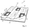
- Fig. 3 illustrates in a three-dimensional view an exemplifying solar powered lighting arrangement 301 in accordance with a third embodiment of the present invention.
- the illustrated solar powered lighting arrangement 301 resembles those described in conjunction with Figs. 1 and 2 , why only distinctive differences are discussed in the following.
- the structural member 303 of Fig. 3 is here a large structure making part of a corrugated metal roof, and may hence similar to the second embodiment of Fig. 2 be convenient for instance for indoor lighting.
- the solar powered lighting arrangement 301 of Fig. 3 comprises a plurality of solar cells or panels 302 arranged across the first side 304 of the structural member 303 and a plurality of light sources 308 arranged across the second side.
- Each solar cell 302 is here provided with four first reflective surfaces 305 for directing sunlight towards the corresponding solar cell 302, and two light sources 308. Note that the positioning as well as the number of solar cells 302, reflective surfaces 305 and light sources 308 are exemplifying, and that other feasible constellations likewise are within the scope.
- the solar cells 302 are here disposed in arrays such that a matrix is formed, whereby the solar powered lighting arrangement 301 may present a package solution spread over a larger roof area rather than provided at a single point.
- the exemplifying solar powered lighting arrangement 301 of Fig. 3 furthermore comprises a diffuser layer 330 for diffusing light emitted from the light sources 308.
- the diffuser layer 330 may provide for light emitted from the light sources 308 to be scattered or spread in a manner appropriate for the implementation at hand.
- the diffuser layer 330 may additionally assist in protecting for instance the second side 307, or at least the light sources 308, from the surrounding environment.
- the diffuser layer 330 is arranged below the light source(s) 308 across the entire structural member 303. Note, however, that such a diffuser layer 330 for instance likewise may cover only one or a few of the light sources 308 and may be positioned differently of have a different shape should that be feasible for the implementation in mind.
- the structural member 303 may hence as well in this third embodiment act as a heat sink for dissipation of heat generated by the light sources 308, constitute a luminaire for the light sources 308, as well as function as a reflector 305 directing sunlight 306 towards the solar cells 302.
Description
- The present invention relates to a solar powered lighting arrangement comprising a solar cell and a light source adapted to be at least partly powered by electrical power derived from the solar cell.
- Bringing artificial light to rural areas may be an approach for development of communities as well as countries. Normal lighting solutions may however not be feasible in many of these rural areas as they often are off-grid, i.e. not covered by power transmission networks. In such situations, one known manner to bring light may be to install solar powered lighting utilizing photovoltaic cells (solar cells) for the purpose of electrical power production. Electrical power may be stored in rechargeable batteries for subsequent use; for instance to power one or several luminaries comprising light sources, which may bring light to the rural area during dark hours.
- In order to reduce expenses related to electrical power production from solar cells, it may be advantageous to utilize reflecting mirrors such as concentrators. Concentrators may be adapted to focus a large area of sunlight into a smaller beam directed towards the solar cells. In this manner, the solar cells may take advantage of an increased amount of sunlight, whereby an increased amount of electricity can be produced. To reach a certain level of electrical power production, fewer cells may hence be needed for a solar panel solution comprising concentrators than for a solution lacking the same. Such an approach is for instance described in
DE 44 33 476 , disclosing a method of enhancing the performance level of photovoltaic systems in a cost efficient manner. InDE 44 33 476 , low outlay on equipment is achieved in that sunlight is concentrated onto the photovoltaic system by means of a reflective system having reflecting faces, which faces consist of colored and therefore wavelength-selective mirrors. -
US2008/0232094 A1 discloses an electrical post lamp with a body with at least three light transmitting sides, a base member for mounting the body on a post, and a top member for shedding precipitation and airborne dirt. The body includes a lighting element, a rechargeable battery for powering the lighting element, a photosensitive switching element for activating the lighting element during the night and deactivating the element during daylight, and a solar collector including at least one solar panel for recharging the battery during daylight. The top member incorporates the solar collector panels. A mirror may be provided for reflecting sunlight onto the North-facing or South-facing portion of the solar collector on the top member. -
DE202005004070U1 discloses a solar-powered advertising banner which acts as a stand-alone unit with a refill system. A transparent housing is illuminated with commonly known lighting devices powered by a solar battery which is loaded by a solar module. -
DE 1020070041842A -
GB2408395A - Although
DE 44 33 476 describes a manner in which to save cost by introducing wavelength-selective mirrors such that fewer photovoltaic cells may be required, there is still a need to lessen expenses with regards to additional components utilized in known solutions for provision of solar powered lighting. Hence there is a need for an arrangement in which the above-related drawbacks are at least partly eliminated. - According to the invention, the above is at least partly met by a solar powered lighting arrangement, comprising a solar cell; a light source adapted to be at least partly powered by electrical power derived from the solar cell; and a structural member having a first side provided with a first reflective surface arranged to direct sunlight towards the solar cell and a second side, opposed to the first side, onto which the light source is arranged and thermally coupled for dissipating heat generated by the light source when emitting light.
- With a solar powered lighting arrangement in accordance with the present invention, the structural member may consequently function not only as a reflector for directing sunlight towards the solar cell, but additionally as a heat sink for the light source. The first reflective surface of the first side is adapted to focus a large area of sunlight into a smaller beam directed towards the solar cell, while the second side of the structural member is acting as a cooling device adapted for transfer of thermal energy (heat) from the light source, thereby lowering the temperature of the light source. A separate heat sink for dissipation of heat generated by the light source when emitting light is hence no longer necessary, as the light source to this end is thermally coupled to the structural member. Neither is a separate luminaire needed, as the light source may be integrated with the structural member which may be capable of directing light emitted by the light source. Fewer components are thus required with the introduced solar powered lighting arrangement as compared to known solutions, thereby providing a cost effective approach.
- The solar powered lighting arrangement may be utilized for any suitable implementation, such as for instance for providing street lighting in a rural area or for indoor lighting for people living in the e.g. slum. In the former case, one or several light sources may be coupled to the second side of the structural member and arranged to direct light emitted from the light source essentially towards the ground, whereby efficient solar powered street lighting may be provided. In the latter case, the solar powered lighting arrangement may be part of a e.g. metal corrugated roof of a e.g. simple shed, with the solar cell and first side of the structural member facing the sun and the second side of the structural member facing the inside of the shed. Thereby, a simple and effective solution is provided facilitating cheaper solar powered indoor lighting.
- The structural member may be of any shape and of any combination of materials appropriate for dissipating heat in conjunction with directing sunlight towards the solar cell. A solid single material structural member is within the scope of the invention as well as a sandwiched structural member comprising a plurality of layers. Furthermore, desired effects of e.g. the first reflective surface or the second side may even be achieved by coating the structural member. The first reflective surface of the first side may preferably be shaped to direct sunlight towards the cell in an optimal manner, and may hence for instance be concave-shaped. Additionally, the first reflective surface may comprise any material providing a mirroring effect on incoming sunlight, such as for instance metal, stainless steel, aluminum alloys, silver coated polymers or silver coated hardened glass or a combination thereof. Furthermore, the second side may preferably be shaped for preferably rapid transfer of thermal energy (heat) from the light source, and may hence be of a size and/or thickness sufficient for the implementation at hand. Additionally, the second side may comprise any material providing heat sink characteristics, such as for instance metal.
- According to one embodiment, the structural member may be a metal plate. Thereby, the structural member is of an optimal shape and material for directing sunlight towards the solar cell in combination with providing heat sink characteristics for dissipating heat generated by the light source when emitting light. Such a metal plate may for instance be utilized for a solar powered street lighting arrangement, with one or several light sources thermally coupled to a convex second side of the structural member and with a concave reflective surface of the first side to a great extent covering the first side.
- In order to assist in spreading light emitted by the light source in an efficient manner, the second side of the structural member may be provided with a second reflective surface arranged to direct light emitted by the light source. Thereby, the second side may not only enable heat dissipation, but may additionally be adapted to reflect light emitted by the light source in a preferred manner. The second reflective surface may for instance be arranged to assist in directing light emitted by the light source in a preferred direction, or arranged to spread the light.
- The light source comprised in the introduced solar powered lighting arrangement may be of any type applicable for the implementation at hand, and may according to one embodiment comprise at least one light emitting diode (LED). An LED represents a choice of light source enabling for a long term of life as well as robustness. A heat sink is particularly necessary when utilizing an LED in comparison to e.g. a traditional light bulb for maintaining the LED's potential long term of life, why the structural member to which the LED is thermally coupled for dissipation of heat is especially beneficial in combination with one or several LEDs. It would however be possible, and within the scope of the present invention, to use different types of light sources, such as organic light emitting diodes (OLEDs), polymeric LEDs (PLEDs), inorganic LEDs, lasers, or a combination thereof, as well as a wide-band (direct of phosphor converted) LED and wide-band (phosphor converted) white LEDs. Furthermore, combinations with other light sources like TL, CFL are also possible.
- In order to enable for an increased amount of electrical power to be generated, the solar cell may be comprised in an interconnected assembly of a plurality of solar cells. Thereby, the solar cell may be part of a solar panel efficiently providing a package solution if more than one solar cell is available for implementation. For further reasons such as cost and practicality, a number of cells may hence be connected electrically and packaged in a solar panel. By mechanically fastening the solar cells together, for instance with a covering hood of e.g. glass and a frame, the solar cells may furthermore be protected from the surrounding environment and subsequently from e.g. dust, rain, hail, and dust storms.
- The greatest need for artificial lighting may occur during the dark hours, why the light source preferably is enabled to emit light also after the sun sets. Subsequently, the solar powered lighting arrangement may further comprise an intermediate storage unit for storing electrical power from the solar cell. With such an intermediate storage unit, for instance a rechargeable battery, the solar powered lighting arrangement may store electrical power generated from the solar cell during the e.g. day, for subsequent use for instance as the night falls when the need for artificial light may be greater.
- In order to avoid wastefulness of electrical power, the solar powered lighting arrangement may further comprise a presence detection sensor adapted to activate the light source. With such a presence detection sensor, the light source may be switched on if someone or something comes within the coverage area of the sensor, meanwhile being switched off if for instance no movement or body heat is detected within the area. Thereby, energy waste may be avoided in that the light source is activated only when considered necessary, and electrical power for instance stored within the intermediate storage unit may be allowed to last longer.
- In an effort to maximize the amount of sun hitting the first reflective surface of the first side of the structural member subsequently directed towards the solar cell, the solar powered lighting arrangement may further be adapted to angle the first reflective surface of the first side such that a focal point of sun light is kept upon the solar cell as the sun moves across the sky. By implementation of for instance a solar tracker detecting the position of the sun, the first reflective surface may be arranged to be tilted or rearranged such that the sun light may be optimally directed towards the solar cell regardless of the time of the day. Rearrangement of the first reflecting surface may for some embodiments imply that the entire structural member or at least a great part of it is physically affected.
- To be able to control the functionality of the solar powered lighting arrangement, such as for instance activation of the light source and/or tilting of the first reflective surface discussed in the foregoing, the solar powered lighting arrangement may further comprise a control unit for control of the arrangement. Such a control unit may alternatively or additionally be adapted to for instance control in which direction light emitted from the light source is directed or reflected, and/or composition of emitted light, e.g. control of color and/or intensity, should more than one e.g. differently (primary) colored light source be available.
- In order to be able to provide e.g. a softer light from the light source, the solar powered lighting arrangement may further comprise a diffuser layer for diffusing light emitted from the light source. By applying such a layer for instance in the vicinity of the light source, light emitted from the light source may be scattered or spread in a manner appropriate for the implementation at hand. The diffuser layer may additionally assist in protecting for instance the second side, or at least the light source, from the surrounding environment.
- According to one embodiment, the solar powered lighting arrangement is arranged on a standing pole. Thereby, a means for efficient mounting is provided which may enable for e.g. street lighting in for instance rural areas.
- These and other aspects of the present invention will now be described in more detail, with reference to the appended drawings showing currently preferred embodiments of the invention, in which:
-
Fig. 1 illustrates an exemplifying solar powered lighting arrangement in accordance with a first embodiment of the present invention; -
Fig. 2 presents an exemplifying solar powered lighting arrangement in accordance with a second embodiment of the present invention; and -
Fig. 3 illustrates in a three-dimensional view an exemplifying solar powered lighting arrangement in accordance with a third embodiment of the present invention. - The present invention will now be described more fully hereinafter with reference to the accompanying drawings, in which currently preferred embodiments of the invention are shown. This invention may, however, be embodied in many different forms and should not be construed as limited to the embodiments set forth herein; rather, these embodiments are provided for thoroughness and completeness, and fully convey the scope of the invention to the skilled addressee. Like reference characters refer to like elements throughout.
-
Fig. 1 illustrates an exemplifying solar powered lighting arrangement 1 in accordance with a first embodiment of the present invention. For simplicity, the solar powered lighting arrangement 1 ofFig. 1 comprises a singlesolar cell 2. Note however, that more than one solar cell may be present with the solar powered lighting arrangement 1 such as an interconnected assembly of a plurality of solar cells. The illustrated singlesolar cell 2 may hence likewise be one or several solar panels which further may be provided with a covering hood for protection from the surrounding environment. It is to be understood that thesolar cell 2 may be represented by any applicable solar cell or panel known in the art, and that thesolar cell 2 may be adapted to generate electrical power in a known manner. In order to envisage the ability of the solar powered arrangement 1 to derive electrical power from thesolar cell 2, a means for derivingelectrical power 10 is illustrated. The means for derivingelectrical power 10 may comprise any known solution in the art, and may for instance comprise necessary electrical circuitry and a charge controller. Furthermore, for illustration of ability to store electrical power from thesolar cell 2, anintermediate storage unit 11, e.g. a rechargeable battery, is depicted. - The solar powered lighting arrangement 1 of the present invention may comprise one or several
structural members 3 preferably arranged in the vicinity of thesolar cell 2. The disposition of the structural member(s) 3 may be arbitrary and arranged with the implementation at hand in mind. Thestructural member 3 comprises a first side 4 facing thesolar cell 2, which first side 4 is provided with a firstreflective surface 5 arranged to directsunlight 6 towards thesolar cell 2. The firstreflective surface 5 may comprise any material providing a mirroring effect on incoming sunlight, such as for instance metal, stainless steel, aluminum alloys, silver coated polymers or silver coated hardened glass or a combination thereof. InFig. 1 , thestructural member 3 is essentially a curved plate and may hence direct sunlight towards thesolar cell 2 in an efficient manner. The shape of thestructural member 3 is however by no means restricted to that of the illustrated example; on the contrary, any shape applicable for the application at hand is within the scope. - The
structural member 3 furthermore comprises asecond side 7. InFig. 1 , thesecond side 7 is opposed to the first side 4. An exemplifying disposition of thesecond side 7 will be described later on in conjunction withFig. 2 . - The solar powered lighting arrangement 1 may comprise one or several
light sources 8 adapted to be at least partly powered by electrical power derived from thesolar cell 2. With the provision oflight sources 8, artificial light may be provided e.g. after the sun sets. It should be noted that thelight source 8 may comprise or be accompanied by any number of optical and/or non-optical components to provide a variety of optical effects (not shown). These components may include, but are not limited to, one or more reflective surfaces, lenses, diffusers, and the like, used in different combinations to provide a desired effect. - The light source(s) 8 are arranged onto the
second side 7 and subsequently thermally coupled to thestructural member 3. Thestructural member 3 may hence act as a heat sink for dissipation of heat generated by thelight source 8 when emitting light 9. Note that a separate heat sink for dissipation of heat generated by thelight source 8 hence is not necessary, as thelight source 8 to this end is thermally coupled to thestructural member 3. Neither is a separate luminaire for containing thelight source 8 required, as thelight source 8, as shown, may be integrated with thestructural member 3. In the illustrated example ofFig. 1 , thelight source 8 is an LED. - In order to in an efficient manner function as a heat sink, the
second side 7 is preferably of a material having characteristics to that end. In the illustrated example, the entirestructural member 3 is of metal, i.e. of a solid single material. Thestructural member 3 may alternatively comprise any combination of materials appropriate for dissipating heat in conjunction with directing sunlight towards thesolar cell 2. A sandwiched structural member comprising a plurality of layers is hence likewise within the scope. Furthermore, desired effects of e.g. the firstreflective surface 5 or thesecond side 7 may even be achieved by coating thestructural member 3. - Although not a necessity for the present invention, in the first embodiment, the solar powered lighting arrangement 1 is provided in conjunction with a
standing pole 12. Thereby, the solar powered lighting arrangement 1 may provide e.g. street lighting in dark places such as off-grid rural areas. For efficient street lighting, thelight source 8 is here arranged to direct light 9 emitted from thelight source 8 essentially towards the ground. It should however be noted, that thelight source 8 for other implementations may be arranged to direct light 9 in any other direction;different light sources 8 may even be arranged to direct light 9 in different directions. - The solar powered lighting arrangement 1 may furthermore comprise a
presence detection sensor 13 adapted to activate thelight source 8. The characteristics of thepresence detection sensor 13 may vary, andpresence detection sensor 13 known in the art may be implemented. With apresence detection sensor 13, thelight source 8 may be switched on if someone or something comes within the coverage area of thesensor 13, and switched off if for instance no movement or body heat is detected within that area. The positioning of thepresence detection sensor 13 as well as settings with regards to for instance coverage area, sensitivity and timing parameters may be arbitrary, and may be adjusted with the present implementation in mind. According to alternative embodiment, switching thelight source 8 on and off may be achieved by for instance a switch or remote control rather than by means of apresence detection sensor 13. - In order to maximize the amount of
sun 6 hitting the firstreflective surface 5 subsequently directed towards thesolar cell 2, the solar powered lighting arrangement 1 may further be adapted to angle the firstreflective surface 5 such that afocal point 17 of sun light is kept upon thesolar cell 2 as the sun moves across the sky. According to the first embodiment, asolar tracker 14, which may be known in the art, is provided for detection of the position of the sun. The disposition of thesolar tracker 14 in the illustration is exemplifying, and any arbitrary applicable positioning is likewise within the scope. The firstreflective surface 5 may be arranged to be tilted or rearranged such that thesun light 6 may be optimally directed towards thesolar cell 2 regardless of the time of the day. Such tilting or rearrangement may for instance be enabled withhinges 15 by which thestructural member 3 may be movably attached to e.g. thesolar cell 2 and for instance a motor connected thereto (not shown). Other applicable mounting alternatives enabling for tilting or rearrangement of the firstreflective surface 5, and perhaps even the first side 4 or the entirestructural member 3, are naturally also feasible. - To be able to control the functionality of the solar powered lighting arrangement 1, such as for instance activation of the
light source 8 and/or tilting or rearrangement of the firstreflective surface 5, acontrol unit 16 for control of the solar powered lighting arrangement 1 may be provided. Such acontrol unit 16 may furthermore be adapted to control in which direction light 9 emitted from the light source(s) 8 may be directed or reflected, and/or composition of emitted light, e.g. control of color and/or intensity. In the illustrated example, thecontrol unit 16 is along with the means for derivingelectrical power 10 and theintermediate storage unit 11 depicted to be conveniently placed in conjunction with thepole 12. Note however that the disposition of thesedevices solar cell 2 orstructural member 3, likewise is within the scope. - In use, the solar powered lighting arrangement 1 may function in accordance with the following exemplifying procedure. During the day, the sun may shine on the
solar cell 2 and additionally or alternatively on the firstreflective surface 5 for subsequent reflection ofsunlight 6 towards thesolar cell 2. Electrical power may thereby be generated by the means for derivingelectrical power 10 and stored in theintermediate storage unit 11. As the day passes, thesolar tracker 14 may detect the position of the sun as it moves across the sky, whereby thecontrol unit 16 may rearrange or tilt the first reflecting surface 5 - here the entire structural member 3 - accordingly. As the night falls, or even during daylight should that be preferred, thelight source 8 may be driven by electrical power derived from thesolar cell 2, and activated/deactivated for instance when someone comes within, or leaves, the coverage area of thepresence detector 13. -
Fig. 2 presents an exemplifying solarpowered lighting arrangement 201 in accordance with a second embodiment of the present invention. The illustrated solarpowered lighting arrangement 201 resembles that 1 described in conjunction withFig. 1 , why only distinctive differences are discussed in the following. - The solar
powered lighting arrangement 201 ofFig. 2 is in contrast to that ofFig. 1 shaped to be convenient for instance for indoor lighting. Thestructural member 203 is here a large structure making part of a corrugated roof of a simple shed, with thefirst side 204 of thestructural member 203 facing the sun and thesecond side 207 facing the inside of the shed. Note that thestructure 203 neither necessarily is corrugated, nor necessarily is part of a roof; other implementations may likewise be applicable. - The solar
powered lighting arrangement 201 here comprises a plurality of solar cells orpanels 202 arranged on top of thestructural member 203, i.e. on thefirst side 204. Thefirst side 204 ofFig. 2 may furthermore comprise a plurality of first reflectingsurfaces 205 disposed along thestructural member 203, preferably arranged to in an optimal mannerdirect sunlight 206 towards the respectivesolar cell 202. - According to the second embodiment, a second
reflective surface 220 may be arranged in the vicinity of thelight source 208. The secondreflective surface 220 is here provided along thesecond side 207 of thestructural member 203, preferably arranged to in an optimal mannerdirect light 209 emitted by thelight source 8 in a desired direction, for instance towards the floor, or to spread the light 209. The secondreflective surface 220 may have any shape applicable for the implementation in mind, and may comprise any material, e.g. metal, providing desired reflecting characteristics. The second reflectingsurface 220 may be presented by a separate layer or coating, or may even be represented by the material of thesecond side 207 itself. Thesecond side 207 may comprise and/or be provided with a plurality of such secondreflective surfaces 220 disposed along thestructural member 203, for instance should there be more than onelight source 208 available. - The
power lighting arrangement 201 ofFig. 2 resembles that 1 ofFig. 1 in that thelight source 208 is arranged onto thesecond side 207 and subsequently thermally coupled to thestructural member 203. Thestructural member 203 may hence as well in this second embodiment act as a heat sink for dissipation of heat generated by thelight source 208 when emitting light 209, constitute a luminaire for thelight sources 208, as well as function as areflector 205 for directingsunlight 206 towards thesolar cell 202. -
Fig. 3 illustrates in a three-dimensional view an exemplifying solarpowered lighting arrangement 301 in accordance with a third embodiment of the present invention. The illustrated solarpowered lighting arrangement 301 resembles those described in conjunction withFigs. 1 and 2 , why only distinctive differences are discussed in the following. - The
structural member 303 ofFig. 3 is here a large structure making part of a corrugated metal roof, and may hence similar to the second embodiment ofFig. 2 be convenient for instance for indoor lighting. The solarpowered lighting arrangement 301 ofFig. 3 comprises a plurality of solar cells orpanels 302 arranged across thefirst side 304 of thestructural member 303 and a plurality oflight sources 308 arranged across the second side. Eachsolar cell 302 is here provided with four firstreflective surfaces 305 for directing sunlight towards the correspondingsolar cell 302, and twolight sources 308. Note that the positioning as well as the number ofsolar cells 302,reflective surfaces 305 andlight sources 308 are exemplifying, and that other feasible constellations likewise are within the scope. Thesolar cells 302 are here disposed in arrays such that a matrix is formed, whereby the solarpowered lighting arrangement 301 may present a package solution spread over a larger roof area rather than provided at a single point. - The exemplifying solar
powered lighting arrangement 301 ofFig. 3 furthermore comprises adiffuser layer 330 for diffusing light emitted from thelight sources 308. Thediffuser layer 330 may provide for light emitted from thelight sources 308 to be scattered or spread in a manner appropriate for the implementation at hand. Thediffuser layer 330 may additionally assist in protecting for instance thesecond side 307, or at least thelight sources 308, from the surrounding environment. In the illustrated example, thediffuser layer 330 is arranged below the light source(s) 308 across the entirestructural member 303. Note, however, that such adiffuser layer 330 for instance likewise may cover only one or a few of thelight sources 308 and may be positioned differently of have a different shape should that be feasible for the implementation in mind. - As the
light sources 308 of the third embodiment described in the foregoing similarly to the exemplifying solutions of the first and second embodiments are arranged onto thesecond side 307 and subsequently thermally coupled to thestructure 303, thestructural member 303 may hence as well in this third embodiment act as a heat sink for dissipation of heat generated by thelight sources 308, constitute a luminaire for thelight sources 308, as well as function as areflector 305 directing sunlight 306 towards thesolar cells 302. - The skilled addressee realizes that the present invention by no means is limited to the preferred embodiments described above. On the contrary, the skilled addressee understands that many modifications and variations are possible and within the scope of the appended claims. Variations to the disclosed embodiments can be understood and effected by the skilled addressee in practicing the claimed invention, from a study of the drawings, the disclosure, and the appended claims. In the claims, the word "comprising" does not exclude other elements or steps, and the indefinite article "a" or "an" does not exclude a plurality.
Claims (11)
- A solar powered lighting arrangement (1, 201, 301), comprising:- a solar cell (2, 202, 302);- a light source (8, 208, 308) adapted to be at least partly powered by electrical power derived from the solar cell (2, 202, 302); and- a structural member (3, 203, 303) having a first side (4, 204, 304) provided with a first reflective surface (5, 205, 305) arranged to direct sunlight (6) towards the solar cell (2, 202, 302), characterized in that the structural member (3, 203, 303) has a second side (7, 207, 307), opposed to the first side (4, 204, 304), onto which the light source (8, 208, 308) is arranged and thermally coupled for dissipating heat generated by the light source (8, 208, 308) when emitting light (9, 209).
- Solar powered lighting arrangement (1) according to claim 1, wherein the structural member (3) is a metal plate.
- Solar powered lighting arrangement (201) according to claim 1 or 2, wherein the second side (207) is provided with a second reflective surface (220) arranged to direct light (209) emitted by the light source (208).
- Solar powered lighting arrangement (1) according to any one of the preceding claims, wherein said light source (8) comprises at least one light emitting diode (LED):
- Solar powered lighting arrangement (1) according to any one of the preceding claims, wherein said solar cell (2) is comprised in an interconnected assembly of a plurality of solar cells.
- Solar powered lighting arrangement (1) according to any one of the preceding claims, further comprising an intermediate storage unit (11) for storing electrical power from the solar cell (2).
- Solar powered lighting arrangement (1) according to any one of the preceding claims, further comprising a presence detection sensor (13) adapted to activate the light source (8).
- Solar powered lighting arrangement (1) according to any one of the preceding claims, wherein said arrangement (1) is adapted to angle said first reflective surface (5) of the first side (4) such that a focal point (17) of sun light is kept upon said solar cell (2) as the sun moves across the sky.
- Solar powered lighting arrangement (1) according to any one of the preceding claims, further comprising a control unit (16) for control of the arrangement (1).
- Solar powered lighting arrangement (301) according to any one of the preceding claims, further comprising a diffuser layer (330) for diffusing light emitted from said light source (308).
- Solar powered lighting arrangement (1) according to any one of the preceding claims, wherein said arrangement (1) is arranged on a standing pole (12).
Priority Applications (1)
| Application Number | Priority Date | Filing Date | Title |
|---|---|---|---|
| EP10730860.3A EP2446187B1 (en) | 2009-06-25 | 2010-06-22 | Solar powered lighting arrangement |
Applications Claiming Priority (3)
| Application Number | Priority Date | Filing Date | Title |
|---|---|---|---|
| EP09163752 | 2009-06-25 | ||
| EP10730860.3A EP2446187B1 (en) | 2009-06-25 | 2010-06-22 | Solar powered lighting arrangement |
| PCT/IB2010/052828 WO2010150193A1 (en) | 2009-06-25 | 2010-06-22 | Solar powered lighting arrangement |
Publications (2)
| Publication Number | Publication Date |
|---|---|
| EP2446187A1 EP2446187A1 (en) | 2012-05-02 |
| EP2446187B1 true EP2446187B1 (en) | 2015-03-11 |
Family
ID=42463595
Family Applications (1)
| Application Number | Title | Priority Date | Filing Date |
|---|---|---|---|
| EP10730860.3A Not-in-force EP2446187B1 (en) | 2009-06-25 | 2010-06-22 | Solar powered lighting arrangement |
Country Status (9)
| Country | Link |
|---|---|
| US (2) | US8632204B2 (en) |
| EP (1) | EP2446187B1 (en) |
| JP (1) | JP5685588B2 (en) |
| KR (1) | KR20120060814A (en) |
| CN (1) | CN102459999B (en) |
| BR (1) | BRPI1010149A2 (en) |
| RU (1) | RU2538756C2 (en) |
| TW (1) | TW201110387A (en) |
| WO (1) | WO2010150193A1 (en) |
Families Citing this family (13)
| Publication number | Priority date | Publication date | Assignee | Title |
|---|---|---|---|---|
| JP5685588B2 (en) * | 2009-06-25 | 2015-03-18 | コーニンクレッカ フィリップス エヌ ヴェ | Solar-powered lighting system |
| WO2013112831A1 (en) * | 2012-01-25 | 2013-08-01 | Lucintech, Inc. | Intrinsically semitransparent solar cell and method of controlling transmitted color spectrum |
| ITBO20120206A1 (en) * | 2012-04-17 | 2013-10-18 | Gpiii S R L | LIGHTING GROUP |
| DE102014103938A1 (en) * | 2014-03-21 | 2015-09-24 | Faurecia Innenraum Systeme Gmbh | Motor vehicle interior trim part with OLED |
| WO2016200276A1 (en) * | 2015-06-11 | 2016-12-15 | Aslaksen Cpv | Floating, concentrating photovoltaic system |
| RU2649724C2 (en) * | 2015-08-10 | 2018-04-04 | Закрытое Акционерное Общество "Скб" | Method of self-contained supply from solar energy |
| CN105258066A (en) * | 2015-11-20 | 2016-01-20 | 苏州铭冠软件科技有限公司 | Energy-saved and environment-friendly concave surface OLED spotlight |
| RU169966U1 (en) * | 2016-07-06 | 2017-04-11 | Александр Александрович Романенко | PHOTOELECTRIC AUTONOMOUS LAMP |
| TW201832840A (en) | 2016-10-10 | 2018-09-16 | 荷蘭商皇家飛利浦有限公司 | Light emitting arrangement configured to realize anti-fouling of a protected surface |
| DE102018117228A1 (en) * | 2017-07-18 | 2019-01-24 | Magna Closures Inc. | Solar panel carrier and drive system |
| KR101953793B1 (en) * | 2018-04-19 | 2019-06-11 | (주)이앤피엔지니어링 | Lighting device using thermoelectric module |
| KR102273986B1 (en) * | 2019-09-11 | 2021-07-08 | 솔랩 주식회사 | Street light with a roof type double-sided light-receiving solar cell |
| IT201900023073A1 (en) * | 2019-12-06 | 2021-06-06 | Remo Scalia | Photoluminescence device |
Family Cites Families (17)
| Publication number | Priority date | Publication date | Assignee | Title |
|---|---|---|---|---|
| DE4433476A1 (en) | 1994-07-27 | 1995-03-23 | Peter Dipl Ing Busch | Method for increasing the efficiency of photovoltaic systems |
| DE20004250U1 (en) | 2000-03-10 | 2000-09-07 | Solartechnik R Pfister | Luminaire for streets and squares |
| JP3086473U (en) * | 2001-12-05 | 2002-06-21 | 朝祥 王 | Solar energy street light devices |
| JP2004281327A (en) * | 2003-03-18 | 2004-10-07 | Kictec Inc | Illuminating lamp device |
| GB2408395A (en) * | 2003-11-24 | 2005-05-25 | Robert Francis Fray | Cylindrical solar street light |
| DE202005004070U1 (en) * | 2005-03-07 | 2005-11-03 | Derksen, Bernward, Dipl.-Architekt | Solar operated advertising banner, has banner housing that is illuminated by commercial lighting unit, where lighting unit is provided with solar rechargeable battery that is charged by solar modules connected with tracking system |
| JP2007150220A (en) * | 2005-11-29 | 2007-06-14 | Kiminori Matsuura | Photovoltaic reflection device for solar power generation |
| JP2007150020A (en) | 2005-11-29 | 2007-06-14 | Seiko Epson Corp | Semiconductor manufacturing apparatus and semiconductor device manufacturing method |
| US7766511B2 (en) | 2006-04-24 | 2010-08-03 | Integrated Illumination Systems | LED light fixture |
| US20080029035A1 (en) * | 2006-08-02 | 2008-02-07 | Jun Gou | Solar powered bird feeder |
| CN200982571Y (en) * | 2006-12-15 | 2007-11-28 | 陈瑞时 | Integral optically focused solar lighting device |
| US20080232094A1 (en) | 2007-03-20 | 2008-09-25 | William Sanner Ramsdell | Solar powered post lamp |
| WO2009016563A1 (en) | 2007-08-02 | 2009-02-05 | Koninklijke Philips Electronics N.V. | Reflector and light output device |
| DE102007041842A1 (en) | 2007-08-27 | 2009-03-05 | Swb Netze Gmbh & Co. Kg | Street lighting controlling method, involves providing generated electrical energy as alternating voltage by inverter module for supplying into mains supply of electrical line from photovoltaic generator to network connection |
| RU75003U1 (en) * | 2008-03-04 | 2008-07-20 | Алексей Иванович Буцких | MOBILE LIGHTING DEVICE (OPTIONS) |
| TWM362369U (en) * | 2009-03-20 | 2009-08-01 | Acpa Energy Conversion Devices Co Ltd | Reflective light wavelength modulation device |
| JP5685588B2 (en) * | 2009-06-25 | 2015-03-18 | コーニンクレッカ フィリップス エヌ ヴェ | Solar-powered lighting system |
-
2010
- 2010-06-22 JP JP2012516938A patent/JP5685588B2/en not_active Expired - Fee Related
- 2010-06-22 CN CN201080028442.7A patent/CN102459999B/en not_active Expired - Fee Related
- 2010-06-22 KR KR1020127001899A patent/KR20120060814A/en not_active Application Discontinuation
- 2010-06-22 WO PCT/IB2010/052828 patent/WO2010150193A1/en active Application Filing
- 2010-06-22 BR BRPI1010149A patent/BRPI1010149A2/en not_active IP Right Cessation
- 2010-06-22 TW TW099120309A patent/TW201110387A/en unknown
- 2010-06-22 US US13/380,573 patent/US8632204B2/en not_active Expired - Fee Related
- 2010-06-22 RU RU2012102429/07A patent/RU2538756C2/en active
- 2010-06-22 EP EP10730860.3A patent/EP2446187B1/en not_active Not-in-force
-
2013
- 2013-12-13 US US14/105,631 patent/US9562659B2/en active Active
Also Published As
| Publication number | Publication date |
|---|---|
| CN102459999A (en) | 2012-05-16 |
| CN102459999B (en) | 2015-08-26 |
| RU2538756C2 (en) | 2015-01-10 |
| RU2012102429A (en) | 2013-07-27 |
| US20120162972A1 (en) | 2012-06-28 |
| EP2446187A1 (en) | 2012-05-02 |
| US8632204B2 (en) | 2014-01-21 |
| US9562659B2 (en) | 2017-02-07 |
| JP5685588B2 (en) | 2015-03-18 |
| WO2010150193A1 (en) | 2010-12-29 |
| JP2012531705A (en) | 2012-12-10 |
| US20140104821A1 (en) | 2014-04-17 |
| BRPI1010149A2 (en) | 2016-03-29 |
| KR20120060814A (en) | 2012-06-12 |
| TW201110387A (en) | 2011-03-16 |
Similar Documents
| Publication | Publication Date | Title |
|---|---|---|
| EP2446187B1 (en) | Solar powered lighting arrangement | |
| JP2012531705A5 (en) | ||
| JP5321259B2 (en) | ROOF STRUCTURE WITH LIGHTING DEVICE, CARPORT ROOF AND WAITING SPACE ROOF USING THE SAME | |
| US20080232094A1 (en) | Solar powered post lamp | |
| JP4690940B2 (en) | Wind and rain avoidance structure | |
| US20110305010A1 (en) | Pole with solar modules | |
| KR101995634B1 (en) | Device stand-alone type led garden lighting with multilayered structure of solar cell module substrate and light lamp | |
| US5228772A (en) | Solar powered lamp having a cover containing a fresnel lens structure | |
| KR101349235B1 (en) | LED Traffic Safety Sign Apparatus Using Solar Panel | |
| KR101030802B1 (en) | Device for stand-alone type led garden-light using solar energy | |
| KR20170052890A (en) | Solar energy-driven lighting system | |
| KR102089366B1 (en) | Back side penetration type photovoltaic system | |
| JP2006244710A (en) | Lighting system | |
| JP2008015438A (en) | Optical light source lamp signboard | |
| US20190093841A1 (en) | Solar Tube | |
| KR20150099694A (en) | Road lighting unit combined with solar module | |
| JP5910677B2 (en) | ROOF STRUCTURE WITH LIGHTING DEVICE, CARPORT ROOF AND WAITING SPACE ROOF USING THE SAME | |
| JP4407777B2 (en) | Lighting device | |
| JP2006086313A (en) | Solar cell power generation system | |
| KR102163812B1 (en) | Device lighting withmultilayered structure of solar cell module substrate and light lamp | |
| JP2012186234A (en) | Photovoltaic power generator | |
| JP2009295836A (en) | Solar cell integrating device | |
| KR20230043496A (en) | All-in-one lamp with improved light collection efficiency | |
| JP6761298B2 (en) | Lighting equipment | |
| CN114415359A (en) | Lighting device based on solar energy convergence power generation |
Legal Events
| Date | Code | Title | Description |
|---|---|---|---|
| PUAI | Public reference made under article 153(3) epc to a published international application that has entered the european phase |
Free format text: ORIGINAL CODE: 0009012 |
|
| 17P | Request for examination filed |
Effective date: 20120125 |
|
| AK | Designated contracting states |
Kind code of ref document: A1 Designated state(s): AL AT BE BG CH CY CZ DE DK EE ES FI FR GB GR HR HU IE IS IT LI LT LU LV MC MK MT NL NO PL PT RO SE SI SK SM TR |
|
| DAX | Request for extension of the european patent (deleted) | ||
| RAP1 | Party data changed (applicant data changed or rights of an application transferred) |
Owner name: KONINKLIJKE PHILIPS N.V. |
|
| 17Q | First examination report despatched |
Effective date: 20131101 |
|
| GRAP | Despatch of communication of intention to grant a patent |
Free format text: ORIGINAL CODE: EPIDOSNIGR1 |
|
| RIC1 | Information provided on ipc code assigned before grant |
Ipc: F21V 7/20 20060101ALI20140903BHEP Ipc: F21S 9/03 20060101ALI20140903BHEP Ipc: H01L 31/052 20140101ALI20140903BHEP Ipc: F21S 8/08 20060101ALI20140903BHEP Ipc: F21Y 101/02 20060101ALN20140903BHEP Ipc: F21V 29/00 20060101AFI20140903BHEP |
|
| INTG | Intention to grant announced |
Effective date: 20140922 |
|
| GRAS | Grant fee paid |
Free format text: ORIGINAL CODE: EPIDOSNIGR3 |
|
| REG | Reference to a national code |
Ref country code: DE Ref legal event code: R079 Ref document number: 602010023046 Country of ref document: DE Free format text: PREVIOUS MAIN CLASS: F21S0008080000 Ipc: F21V0029000000 |
|
| GRAA | (expected) grant |
Free format text: ORIGINAL CODE: 0009210 |
|
| AK | Designated contracting states |
Kind code of ref document: B1 Designated state(s): AL AT BE BG CH CY CZ DE DK EE ES FI FR GB GR HR HU IE IS IT LI LT LU LV MC MK MT NL NO PL PT RO SE SI SK SM TR |
|
| REG | Reference to a national code |
Ref country code: GB Ref legal event code: FG4D |
|
| RIC1 | Information provided on ipc code assigned before grant |
Ipc: F21V 29/00 20150101AFI20150130BHEP Ipc: H01L 31/052 20140101ALI20150130BHEP Ipc: F21S 9/03 20060101ALI20150130BHEP Ipc: F21S 8/08 20060101ALI20150130BHEP Ipc: F21V 29/505 20150101ALI20150130BHEP Ipc: F21Y 101/02 20060101ALN20150130BHEP |
|
| REG | Reference to a national code |
Ref country code: CH Ref legal event code: EP |
|
| REG | Reference to a national code |
Ref country code: IE Ref legal event code: FG4D |
|
| REG | Reference to a national code |
Ref country code: AT Ref legal event code: REF Ref document number: 715556 Country of ref document: AT Kind code of ref document: T Effective date: 20150415 |
|
| REG | Reference to a national code |
Ref country code: DE Ref legal event code: R096 Ref document number: 602010023046 Country of ref document: DE Effective date: 20150423 |
|
| REG | Reference to a national code |
Ref country code: NL Ref legal event code: VDEP Effective date: 20150311 |
|
| REG | Reference to a national code |
Ref country code: NL Ref legal event code: VDEP Effective date: 20150311 |
|
| PG25 | Lapsed in a contracting state [announced via postgrant information from national office to epo] |
Ref country code: HR Free format text: LAPSE BECAUSE OF FAILURE TO SUBMIT A TRANSLATION OF THE DESCRIPTION OR TO PAY THE FEE WITHIN THE PRESCRIBED TIME-LIMIT Effective date: 20150311 Ref country code: SE Free format text: LAPSE BECAUSE OF FAILURE TO SUBMIT A TRANSLATION OF THE DESCRIPTION OR TO PAY THE FEE WITHIN THE PRESCRIBED TIME-LIMIT Effective date: 20150311 Ref country code: NO Free format text: LAPSE BECAUSE OF FAILURE TO SUBMIT A TRANSLATION OF THE DESCRIPTION OR TO PAY THE FEE WITHIN THE PRESCRIBED TIME-LIMIT Effective date: 20150611 Ref country code: ES Free format text: LAPSE BECAUSE OF FAILURE TO SUBMIT A TRANSLATION OF THE DESCRIPTION OR TO PAY THE FEE WITHIN THE PRESCRIBED TIME-LIMIT Effective date: 20150311 Ref country code: LT Free format text: LAPSE BECAUSE OF FAILURE TO SUBMIT A TRANSLATION OF THE DESCRIPTION OR TO PAY THE FEE WITHIN THE PRESCRIBED TIME-LIMIT Effective date: 20150311 Ref country code: FI Free format text: LAPSE BECAUSE OF FAILURE TO SUBMIT A TRANSLATION OF THE DESCRIPTION OR TO PAY THE FEE WITHIN THE PRESCRIBED TIME-LIMIT Effective date: 20150311 |
|
| REG | Reference to a national code |
Ref country code: AT Ref legal event code: MK05 Ref document number: 715556 Country of ref document: AT Kind code of ref document: T Effective date: 20150311 |
|
| REG | Reference to a national code |
Ref country code: LT Ref legal event code: MG4D |
|
| PG25 | Lapsed in a contracting state [announced via postgrant information from national office to epo] |
Ref country code: LV Free format text: LAPSE BECAUSE OF FAILURE TO SUBMIT A TRANSLATION OF THE DESCRIPTION OR TO PAY THE FEE WITHIN THE PRESCRIBED TIME-LIMIT Effective date: 20150311 Ref country code: GR Free format text: LAPSE BECAUSE OF FAILURE TO SUBMIT A TRANSLATION OF THE DESCRIPTION OR TO PAY THE FEE WITHIN THE PRESCRIBED TIME-LIMIT Effective date: 20150612 |
|
| PG25 | Lapsed in a contracting state [announced via postgrant information from national office to epo] |
Ref country code: NL Free format text: LAPSE BECAUSE OF FAILURE TO SUBMIT A TRANSLATION OF THE DESCRIPTION OR TO PAY THE FEE WITHIN THE PRESCRIBED TIME-LIMIT Effective date: 20150311 |
|
| PG25 | Lapsed in a contracting state [announced via postgrant information from national office to epo] |
Ref country code: SK Free format text: LAPSE BECAUSE OF FAILURE TO SUBMIT A TRANSLATION OF THE DESCRIPTION OR TO PAY THE FEE WITHIN THE PRESCRIBED TIME-LIMIT Effective date: 20150311 Ref country code: PT Free format text: LAPSE BECAUSE OF FAILURE TO SUBMIT A TRANSLATION OF THE DESCRIPTION OR TO PAY THE FEE WITHIN THE PRESCRIBED TIME-LIMIT Effective date: 20150713 Ref country code: CZ Free format text: LAPSE BECAUSE OF FAILURE TO SUBMIT A TRANSLATION OF THE DESCRIPTION OR TO PAY THE FEE WITHIN THE PRESCRIBED TIME-LIMIT Effective date: 20150311 Ref country code: EE Free format text: LAPSE BECAUSE OF FAILURE TO SUBMIT A TRANSLATION OF THE DESCRIPTION OR TO PAY THE FEE WITHIN THE PRESCRIBED TIME-LIMIT Effective date: 20150311 Ref country code: RO Free format text: LAPSE BECAUSE OF FAILURE TO SUBMIT A TRANSLATION OF THE DESCRIPTION OR TO PAY THE FEE WITHIN THE PRESCRIBED TIME-LIMIT Effective date: 20150311 |
|
| PG25 | Lapsed in a contracting state [announced via postgrant information from national office to epo] |
Ref country code: AT Free format text: LAPSE BECAUSE OF FAILURE TO SUBMIT A TRANSLATION OF THE DESCRIPTION OR TO PAY THE FEE WITHIN THE PRESCRIBED TIME-LIMIT Effective date: 20150311 Ref country code: PL Free format text: LAPSE BECAUSE OF FAILURE TO SUBMIT A TRANSLATION OF THE DESCRIPTION OR TO PAY THE FEE WITHIN THE PRESCRIBED TIME-LIMIT Effective date: 20150311 Ref country code: IS Free format text: LAPSE BECAUSE OF FAILURE TO SUBMIT A TRANSLATION OF THE DESCRIPTION OR TO PAY THE FEE WITHIN THE PRESCRIBED TIME-LIMIT Effective date: 20150711 |
|
| REG | Reference to a national code |
Ref country code: DE Ref legal event code: R097 Ref document number: 602010023046 Country of ref document: DE |
|
| PG25 | Lapsed in a contracting state [announced via postgrant information from national office to epo] |
Ref country code: IT Free format text: LAPSE BECAUSE OF FAILURE TO SUBMIT A TRANSLATION OF THE DESCRIPTION OR TO PAY THE FEE WITHIN THE PRESCRIBED TIME-LIMIT Effective date: 20150311 |
|
| PLBE | No opposition filed within time limit |
Free format text: ORIGINAL CODE: 0009261 |
|
| STAA | Information on the status of an ep patent application or granted ep patent |
Free format text: STATUS: NO OPPOSITION FILED WITHIN TIME LIMIT |
|
| PG25 | Lapsed in a contracting state [announced via postgrant information from national office to epo] |
Ref country code: DK Free format text: LAPSE BECAUSE OF FAILURE TO SUBMIT A TRANSLATION OF THE DESCRIPTION OR TO PAY THE FEE WITHIN THE PRESCRIBED TIME-LIMIT Effective date: 20150311 Ref country code: MC Free format text: LAPSE BECAUSE OF FAILURE TO SUBMIT A TRANSLATION OF THE DESCRIPTION OR TO PAY THE FEE WITHIN THE PRESCRIBED TIME-LIMIT Effective date: 20150311 |
|
| REG | Reference to a national code |
Ref country code: CH Ref legal event code: PL |
|
| 26N | No opposition filed |
Effective date: 20151214 |
|
| PG25 | Lapsed in a contracting state [announced via postgrant information from national office to epo] |
Ref country code: LU Free format text: LAPSE BECAUSE OF FAILURE TO SUBMIT A TRANSLATION OF THE DESCRIPTION OR TO PAY THE FEE WITHIN THE PRESCRIBED TIME-LIMIT Effective date: 20150622 Ref country code: SI Free format text: LAPSE BECAUSE OF FAILURE TO SUBMIT A TRANSLATION OF THE DESCRIPTION OR TO PAY THE FEE WITHIN THE PRESCRIBED TIME-LIMIT Effective date: 20150311 |
|
| REG | Reference to a national code |
Ref country code: IE Ref legal event code: MM4A |
|
| PG25 | Lapsed in a contracting state [announced via postgrant information from national office to epo] |
Ref country code: IE Free format text: LAPSE BECAUSE OF NON-PAYMENT OF DUE FEES Effective date: 20150622 Ref country code: CH Free format text: LAPSE BECAUSE OF NON-PAYMENT OF DUE FEES Effective date: 20150630 Ref country code: LI Free format text: LAPSE BECAUSE OF NON-PAYMENT OF DUE FEES Effective date: 20150630 |
|
| REG | Reference to a national code |
Ref country code: FR Ref legal event code: PLFP Year of fee payment: 7 |
|
| PG25 | Lapsed in a contracting state [announced via postgrant information from national office to epo] |
Ref country code: BE Free format text: LAPSE BECAUSE OF FAILURE TO SUBMIT A TRANSLATION OF THE DESCRIPTION OR TO PAY THE FEE WITHIN THE PRESCRIBED TIME-LIMIT Effective date: 20150311 |
|
| REG | Reference to a national code |
Ref country code: GB Ref legal event code: 732E Free format text: REGISTERED BETWEEN 20161006 AND 20161012 |
|
| PG25 | Lapsed in a contracting state [announced via postgrant information from national office to epo] |
Ref country code: MT Free format text: LAPSE BECAUSE OF FAILURE TO SUBMIT A TRANSLATION OF THE DESCRIPTION OR TO PAY THE FEE WITHIN THE PRESCRIBED TIME-LIMIT Effective date: 20150311 |
|
| REG | Reference to a national code |
Ref country code: DE Ref legal event code: R082 Ref document number: 602010023046 Country of ref document: DE Representative=s name: MEISSNER BOLTE PATENTANWAELTE RECHTSANWAELTE P, DE Ref country code: DE Ref legal event code: R081 Ref document number: 602010023046 Country of ref document: DE Owner name: PHILIPS LIGHTING HOLDING B.V., NL Free format text: FORMER OWNER: KONINKLIJKE PHILIPS N.V., EINDHOVEN, NL |
|
| PG25 | Lapsed in a contracting state [announced via postgrant information from national office to epo] |
Ref country code: BG Free format text: LAPSE BECAUSE OF FAILURE TO SUBMIT A TRANSLATION OF THE DESCRIPTION OR TO PAY THE FEE WITHIN THE PRESCRIBED TIME-LIMIT Effective date: 20150311 Ref country code: HU Free format text: LAPSE BECAUSE OF FAILURE TO SUBMIT A TRANSLATION OF THE DESCRIPTION OR TO PAY THE FEE WITHIN THE PRESCRIBED TIME-LIMIT; INVALID AB INITIO Effective date: 20100622 Ref country code: SM Free format text: LAPSE BECAUSE OF FAILURE TO SUBMIT A TRANSLATION OF THE DESCRIPTION OR TO PAY THE FEE WITHIN THE PRESCRIBED TIME-LIMIT Effective date: 20150311 |
|
| REG | Reference to a national code |
Ref country code: FR Ref legal event code: PLFP Year of fee payment: 8 |
|
| PG25 | Lapsed in a contracting state [announced via postgrant information from national office to epo] |
Ref country code: CY Free format text: LAPSE BECAUSE OF FAILURE TO SUBMIT A TRANSLATION OF THE DESCRIPTION OR TO PAY THE FEE WITHIN THE PRESCRIBED TIME-LIMIT Effective date: 20150311 |
|
| PG25 | Lapsed in a contracting state [announced via postgrant information from national office to epo] |
Ref country code: TR Free format text: LAPSE BECAUSE OF FAILURE TO SUBMIT A TRANSLATION OF THE DESCRIPTION OR TO PAY THE FEE WITHIN THE PRESCRIBED TIME-LIMIT Effective date: 20150311 |
|
| PG25 | Lapsed in a contracting state [announced via postgrant information from national office to epo] |
Ref country code: MK Free format text: LAPSE BECAUSE OF FAILURE TO SUBMIT A TRANSLATION OF THE DESCRIPTION OR TO PAY THE FEE WITHIN THE PRESCRIBED TIME-LIMIT Effective date: 20150311 |
|
| REG | Reference to a national code |
Ref country code: FR Ref legal event code: PLFP Year of fee payment: 9 |
|
| PG25 | Lapsed in a contracting state [announced via postgrant information from national office to epo] |
Ref country code: AL Free format text: LAPSE BECAUSE OF FAILURE TO SUBMIT A TRANSLATION OF THE DESCRIPTION OR TO PAY THE FEE WITHIN THE PRESCRIBED TIME-LIMIT Effective date: 20150311 |
|
| RIC2 | Information provided on ipc code assigned after grant |
Ipc: F21Y 101/02 20000101ALN20150130BHEP Ipc: F21S 8/08 20060101ALI20150130BHEP Ipc: F21V 29/505 20150101ALI20150130BHEP Ipc: F21S 9/03 20060101ALI20150130BHEP Ipc: F21V 29/00 20150101AFI20150130BHEP Ipc: H01L 31/052 20140101ALI20150130BHEP |
|
| PGFP | Annual fee paid to national office [announced via postgrant information from national office to epo] |
Ref country code: FR Payment date: 20200626 Year of fee payment: 11 |
|
| PGFP | Annual fee paid to national office [announced via postgrant information from national office to epo] |
Ref country code: GB Payment date: 20200629 Year of fee payment: 11 |
|
| PGFP | Annual fee paid to national office [announced via postgrant information from national office to epo] |
Ref country code: DE Payment date: 20200630 Year of fee payment: 11 |
|
| REG | Reference to a national code |
Ref country code: DE Ref legal event code: R119 Ref document number: 602010023046 Country of ref document: DE |
|
| GBPC | Gb: european patent ceased through non-payment of renewal fee |
Effective date: 20210622 |
|
| PG25 | Lapsed in a contracting state [announced via postgrant information from national office to epo] |
Ref country code: GB Free format text: LAPSE BECAUSE OF NON-PAYMENT OF DUE FEES Effective date: 20210622 Ref country code: DE Free format text: LAPSE BECAUSE OF NON-PAYMENT OF DUE FEES Effective date: 20220101 |
|
| PG25 | Lapsed in a contracting state [announced via postgrant information from national office to epo] |
Ref country code: FR Free format text: LAPSE BECAUSE OF NON-PAYMENT OF DUE FEES Effective date: 20210630 |