EP2445247A1 - Base station, relay station, wireless communication system and method for wireless communication - Google Patents
Base station, relay station, wireless communication system and method for wireless communication Download PDFInfo
- Publication number
- EP2445247A1 EP2445247A1 EP09846180A EP09846180A EP2445247A1 EP 2445247 A1 EP2445247 A1 EP 2445247A1 EP 09846180 A EP09846180 A EP 09846180A EP 09846180 A EP09846180 A EP 09846180A EP 2445247 A1 EP2445247 A1 EP 2445247A1
- Authority
- EP
- European Patent Office
- Prior art keywords
- station
- wireless communication
- relay station
- amplification
- mobile station
- Prior art date
- Legal status (The legal status is an assumption and is not a legal conclusion. Google has not performed a legal analysis and makes no representation as to the accuracy of the status listed.)
- Withdrawn
Links
Images







Classifications
-
- H—ELECTRICITY
- H04—ELECTRIC COMMUNICATION TECHNIQUE
- H04W—WIRELESS COMMUNICATION NETWORKS
- H04W52/00—Power management, e.g. Transmission Power Control [TPC] or power classes
- H04W52/04—Transmission power control [TPC]
- H04W52/38—TPC being performed in particular situations
- H04W52/46—TPC being performed in particular situations in multi-hop networks, e.g. wireless relay networks
-
- H—ELECTRICITY
- H04—ELECTRIC COMMUNICATION TECHNIQUE
- H04B—TRANSMISSION
- H04B7/00—Radio transmission systems, i.e. using radiation field
- H04B7/14—Relay systems
- H04B7/15—Active relay systems
- H04B7/155—Ground-based stations
- H04B7/15528—Control of operation parameters of a relay station to exploit the physical medium
- H04B7/15535—Control of relay amplifier gain
Definitions
- the present invention relates to a base station, a relay station, a wireless communication system, and a wireless communication method.
- a relay station is conventionally used in wireless communication systems.
- Relay stations include non-regenerating types that amplify and transmit received signals, and regenerating types that amplify and transmit received signals after first decoding the signal and regenerating the original data.
- a system is known that can determine communication paths capable of realizing high speed communication by multi-hop.
- a mobile communication system includes a communication path determining unit that based on the interference level of the signals respectively received by a relay station and a base station, which form a communication path between communicating stations, determines a communication path that offers the fastest communication speed or that satisfies a specified line quality (see, for example, Patent document 1).
- a system that increases the effective area of a spread spectrum-based wireless network as well as communication capacity.
- the system has a wireless communication network that is expanded by a low-cost, channel selector-type relay apparatus capable of relaying desired signals alone (see, for example, Patent document 2).
- An object of the disclosed wireless communication system and wireless communication method is to provide a system and a method that can prevent the relay station from becoming a source of interference.
- Another object of the disclosed base station and relay station is to provide a base station and a relay station that can implement a system capable of preventing the relay station from becoming a source of interference.
- the wireless communication system includes a base station and a relay station.
- the base station includes a selector and a reporter. Based on the wireless communication state with each mobile station, the selector selects a mobile station that requires amplification at the relay station.
- the reporter reports first information related to the mobile station selected by the selector.
- the relay station includes a selector and an amplifier. At the relay station, the selector selects based on the wireless communication state with each mobile, a mobile station candidate for which amplification is to be performed station.
- the amplifier performs amplification, based on second information related to the mobile station candidate selected by the selector and the first information reported by the base station.
- a relay station can prevented from becoming a source of interference.
- the base station selects based on the wireless communication state with each mobile station, a mobile station that requires amplification by the relay station; and reports first information related to the selected mobile station.
- the relay station selects, based on the wireless communication state with each mobile station, a mobile station candidate for which amplification is to be performed; and performs amplification, based on second information related to the selected mobile station candidate and the first information reported by the base station.
- FIG. 1 is a block diagram of a configuration of the wireless communication system according to the first embodiment.
- the wireless communication system includes a base station 1 and a relay station 2.
- the base station 1 includes a selector 3 and a reporter 4.
- the selector 3 selects based on the wireless communication state between the base station 1 and a mobile station 7, a mobile station for which amplification is to be performed at the relay station 2.
- the reporter 4 reports first information related to the mobile station selected by the selector 3.
- the relay station 2 includes a selector 5 and an amplifier 6.
- the selector 5 of the relay station 2 selects based on the wireless communication state between the relay station 2 and the mobile station 7, a mobile station candidate for which amplification is to be performed.
- the amplifier 6 performs amplification, based on second information related to the mobile station candidate selected by the selector 5 of the relay station 2 and the first information reported by the base station 1.
- the number of the relay stations 2 and/or the number of the mobile stations 7 may be plural.
- FIG. 2 is a flowchart of the wireless communication method according to the first embodiment.
- the base station selects based on the wireless communication state with the mobile station, a mobile station for which amplification is to be performed at the relay station (step S1).
- the base station reports information (first information) related to the mobile station selected at step S1 (step S2).
- the relay station selects based on the wireless communication state with the mobile station, a mobile station candidate for which amplification is to be performed (step S3).
- the relay station performs amplification, based on information (second information) related to the mobile station candidate selected at step S3 and the first information reported by the base station at step S2 (step S4).
- step S1 and step S2 are executed in this sequence.
- Step S4 is executed after steps S1, S2, and S3.
- the execution timing of step S3 may be after step S2, before step S2, or before step S1.
- the relay station performs amplification based on information concerning a mobile station that has been selected by the base station, for amplification, and information concerning a mobile station that is regarded as a candidate for amplification by the relay station, thereby enabling configuration to be such that the relay station does not perform amplification when the mobile station regarded as the candidate for amplification by the relay station is not included in the information concerning the mobile station that has been selected by the base station, for amplification. If the radio wave environment around the relay station changes while the relay station is performing amplification and the mobile station that is regarded as the candidate for amplification by the relay station is no longer included in the information concerning the mobile station selected by the base station, the relay station can terminate the amplification.
- the phenomenon of the relay station becoming a source of interference, consequent to the relay station performing amplification when amplification is not necessary, can be prevented.
- the base station selects plural mobile stations to be subject to amplification and plural relay stations are present, the respective relay stations perform amplification if the amplification candidate thereof is included in the information concerning the mobile stations selected by the base station. Consequently, the mobile stations requiring amplification are distributed among the relay stations, enabling amplification to be performed efficiently.
- FIG. 3 is a block diagram of a configuration of the base station according to a second embodiment.
- a base station 11 includes a measurer 12, a table 13, a judger 14, and a generator 15. Via an antenna 16 and a switch 17, the base station 11 receives a wireless signal transmitted from a non-depicted mobile station.
- the measurer 12 measures the wireless communication state between the base station 11 and the mobile station.
- Reception quality (signal to interference power ratio (SIR)) is one example of a wireless communication state.
- the measurer 12 measures the reception quality (SIR) of a common pilot channel between the base station and the mobile station.
- the table 13 stores thresholds used when the wireless communication state is judged.
- the judger 14 compares the wireless communication state and a threshold.
- the judger 14, for example, judges that amplification is not necessary for a mobile station for which the wireless communication state exceeds or is equal to the threshold.
- the wireless signal between the base station and a mobile station, for which amplification is judged to be not necessary is not amplified at a relay station (not depicted).
- the judger 14, for example, judges that amplification is necessary for a mobile station for which the wireless communication state is less than the threshold.
- the wireless signal between the base station and a mobile station for which amplification is judged to be necessary is amplified at a non-depicted relay station.
- the generator 15 generates a list of mobile stations for which amplification has been judged to be necessary.
- the base station 11 reports (broadcasts), via the switch 17 and the antenna 16, the list of mobile stations for which amplification has been judged necessary.
- the antenna 16, the switch 17, the measurer 12, the table 13, and the judger 14, for example, operate as the selector 3 of the base station 1 in the first embodiment.
- the list of mobile stations for which amplification has been judged to be necessary is one example of the first information in the first embodiment.
- FIG. 4 is a block diagram of a configuration of the relay station according to the second embodiment.
- a relay station 21 is a non-regenerating type relay apparatus, for example.
- the relay station 21 includes a measurer 22, a table 23, a first judger 24, a generator 25, a receiver 26, a second judger 27, and an amplifier 28. Via an antenna 29, the relay station 21 receives a wireless signal transmitted from a non-depicted base station or mobile station.
- the measurer 22 measures the wireless communication state between the relay station 21 and the mobile station.
- An example of the wireless communication state is reception quality (SIR).
- SIR reception quality
- the measurer 22 measures the reception quality (SIR) of a common pilot channel between the base station and the mobile station.
- the table 23 stores thresholds used when the wireless communication state is judged.
- the first judger 24 compares the wireless communication state and a threshold. In general, the nearer the mobile station is to the relay station 21, the better the wireless communication state.
- the generator 25 generates a list of mobile station candidates for which amplification is to be performed by the relay station 21.
- the receiver 26 receives and stores the list of mobile stations reported and judged by the base station to require amplification.
- the second judger 27 judges whether to perform amplification at the relay station 21, based on the list of mobile station candidates for which amplification is to be performed and the list of mobile stations judged to require amplification. For example, the second judger 27 judges that amplification is to be performed by the relay station 21, when one or more of the mobile stations included on the list of mobile station candidates for which amplification is to be performed at the relay station 21 is included on the list of mobile stations judged to require amplification.
- the amplifier 28 switches between states of performing amplification operations and not performing amplification operations, based on the judgment results of the second judger 27. When amplification operations are performed by the amplifier 28, a received signal is amplified by the amplifier 28 and the amplified signal is transmitted via an antenna 30.
- the antenna 29, the measurer 22, the table 23, and the first judger 24, for example, operate as the selector 5 of the relay station 2 in the first embodiment.
- the generator 25, the receiver 26, the second judger 27, and the amplifier 28, for example, operate as the amplifier 6 in the first embodiment.
- the list of mobile station candidates for which the relay station 21 is to perform amplification is an example of the second information in the first embodiment.
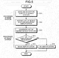
- FIG. 5 is a flowchart of the wireless communication method according to the second embodiment.
- the relay station when a process begins for determining whether amplification is to be performed during wireless communication between a base station and a mobile station, the relay station is in a state of not performing amplification and base station measures the wireless communication state between the base station and the mobile station (step S11). For example, the base station measures the reception quality (SIR) of a common pilot channel between the base station and the mobile station.
- SIR reception quality
- the base station compares the wireless communication state and a preliminarily set threshold, and for example, judges that amplification is necessary for a mobile station for which the wireless communication state does not exceed the threshold.
- the base station generates a list of mobile stations requiring amplification and reports the list (step S12).
- the relay station measures the wireless communication state between the relay station and the mobile station. For example, the relay station measures the reception quality (SIR) of a common pilot channel between the base station and the mobile station.
- the relay station compares the wireless communication state and a preliminarily set threshold and for example, judges a mobile station to be nearby if the wireless communication state thereof exceeds the threshold.
- the relay station generates a list of mobile stations that have been judged to be nearby (a nearby-mobile-station list) (step S13).
- the relay station checks whether the mobile stations judged to be nearby are included on the list of mobile stations reported and judged by the base station to require amplification.
- the relay station judges that amplification is necessary if the mobile stations judged to be nearby are included on the list of mobile stations judged to require amplification, whereas if the mobile stations are not included, the relay station judges that amplification is not necessary (step S14). If the judgment result is that amplification is necessary (step S14: YES), the relay station begins amplification (step S15). If amplification is judged to not be necessary (step S14: NO), the relay station remains in a state of not performing amplification (step S16).
- the base station continuously measures the wireless communication state between the base station and the mobile stations, generates a list of mobile stations requiring amplification, and reports the list.
- the relay station continuously measures the wireless communication state between the relay station and the mobile stations, and generates a list of mobile stations judged to be nearby. In other words, the list of mobile stations judged at the base station, to require amplification and the list of mobile stations judged at the relay station, to be nearby dynamically change.
- the relay station terminates amplification when the mobile station judged to be nearby ceases to be included on the list of mobile stations judged to require amplification.
- steps S13 to S16 are executed at each relay station. In this series of processes, steps S11 and S12 are executed in this sequence.
- Step S14 is executed after steps S11, S12, and S13.
- the execution timing of step S13 may be after step S12, before step S12, or before step 511.
- effects identical to those of the first embodiment are obtained. If the same mobile station is included in the nearby-mobile-station list of plural relay stations, amplification for the mobile station may be performed by the plural relay stations. Further, a regenerating type relay station may be used as the relay station.
- a third embodiment incorporates into the second embodiment, a sharing of the nearby-mobile-station lists among the relay stations.
- Configuration of the base station in the third embodiment is identical to that in the second embodiment.
- Configuration of the relay station in third embodiment is as depicted in FIG. 6 , for example.
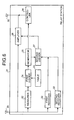
- FIG. 6 is a block diagram of a configuration of the relay station according to the third embodiment.
- a relay station 31 includes a first receiver 32, a second receiver 33, a controller 34, the measurer 22, the table 23, the first judger 24, the generator 25, the second judger 27, and the amplifier 28.
- the first receiver 32 is identical to the receiver 26 of the second embodiment.
- the second receiver 33 receives and stores the nearby-mobile-station lists from other relay stations.
- the controller 34 generates a wireless channel for transmitting the nearby-mobile-station list of the relay station 31 to other relay stations.
- the controller 34 controls the wireless channel and transmits the nearby-mobile-station list of the relay station 31 to other relay stations, via the antenna 30.
- the second judger 27 judges whether amplification at the relay station 31 is to be performed, based on the list of mobile station candidates for which amplification is to be performed at the relay station 31, the list of mobile stations judged to require amplification, and the nearby-mobile-station lists of other relay stations. For example, when the following two conditions are satisfied, the second judger 27 judges that amplification at the relay station 31 is to be performed.
- a first condition is that one or more mobile stations included on the list of mobile station candidates for which amplification is to be performed at the relay station 31, is included on the list of mobile stations judged to require amplification.
- a second condition is that a mobile station that is included in both the list of mobile station candidates for which amplification is to be performed at the relay station 31 and the list of mobile stations judged to require amplification, is located nearer to the relay station 31 than to other relay stations.
- the second judger 27 judges that amplification is not to be performed by the relay station 31, when none of the mobile stations included on the list of mobile station candidates for which amplification is to be performed at the relay station 31 are included on the list of mobile stations judged to require amplification, or when the first condition is satisfied, but the second condition is not.
- Other aspects of the relay station 31 are identical to the second embodiment.
- FIG. 7 is a flowchart of the wireless communication method according to the third embodiment.
- the base station measures the wireless communication state between the base station and the mobile station (step S21), generates a list of mobile station that have been judged to require amplification, and reports the list (step S22). Meanwhile, each relay station generates a list of nearby mobile stations (step S23). The relay stations transmit and receive the lists of nearby mobile stations with one another and thereby share the lists (step S24).
- each relay station judges whether amplification is necessary (step S25). If the judgment result is that amplification is necessary (step S25: YES), the relay station judges whether a mobile station that is included in both the list of mobile station candidates for which amplification is to be performed by the relay station and the list of mobile stations judged to require amplification, is located nearer to the relay station than to other relay stations (step S26). If so (step S26: YES), the relay station begins amplification (step S27).
- step S25 if amplification is not necessary (step S25: NO), or at step S26, if the mobile station is nearer to another relay station (step S26: NO), the relay station remains in a state of not performing amplification (step S28).
- the execution timing of step S23 may be after step S22, before step S22, or before step S21.
- FIG. 8 is a diagram of an example of wireless communication states between the relay station and the mobile station in the third embodiment.
- the wireless communication system is assumed to include relay station A and relay station B in addition to the base station, where mobile station A, mobile station B, and mobile station C are located in a vicinity of relay station A and relay station B.
- the wireless communication state (reception quality, SIR) of each mobile station is assumed to be as depicted in table 35 in FIG. 8 .
- the threshold when judging whether a mobile station is nearby is assumed to be 5dB.
- mobile station B is included on the list of mobile stations that have been judge to be nearby.
- relay station B mobile station B and mobile station A are included on the list of mobile stations that have been judged to be nearby.
- Mobile station B is assumed to be included on the list of mobile stations that have been reported and judged by the base station to require amplification.
- the reception quality of mobile station B is better for relay station A than for relay station B and accordingly, at step S26 in the flowchart depicted in FIG. 7 , mobile station B is judged to be located nearer to relay station A than to relay station B. Therefore, relay station A begins amplification (step S27), and relay station B remains in a state of not performing amplification (step S28).
- the reception quality of mobile station A is favorable, for example, if mobile station A is not included in the list of mobile stations reported and judged by the base station to require amplification, the judgment of whether amplification is necessary is not performed with respect to mobile station A.
- configuration may be such that a relay station transmits the list of nearby mobile stations to another relay station by a wired line.
- a fourth embodiment incorporates into the second embodiment, a changing of the number of mobile stations judged to require amplification, based on interference power within the cell
- the configuration of the base station in the fourth embodiment is, for example, as depicted in FIG. 9 .
- the configuration of the relay station in the fourth embodiment is identical to that in the second embodiment.
- FIG. 9 is a block diagram of a configuration of the base station according to the fourth embodiment.
- FIG. 10 is a table depicting an example of a second table.
- a base station 41 includes a first measurer 42, a first table 43, a second measurer 44, a second table 45, a calculator 46, the judger 14, the generator 15, and the switch 17.
- the first measurer 42 and the first table 43 are respectively identical to the measurer 12 and the table 13 of the second embodiment.
- the second measurer 44 measures the interference power within the cell.
- the second table 45 stores correspondence relations between the interference power within the cell and the number of amplifiable mobile stations (see FIG. 10 ).
- Correspondence relations between the interference power within the cell and the number of amplifiable mobile stations may be preliminarily determined by simulation using a computing device, for example.
- the calculator 46 determines the number of mobile stations that can be amplified, based on the correspondence relation between the interference power within the cell and the number of amplifiable mobile stations, and the interference power within the cell. Using the number of amplifiable mobile stations as an upper limit, the generator 15 generates a list of mobile stations judged to require amplification.
- Other aspects of the base station 41 are identical to the second embodiment.
- 10 , 11 , 12, and 13 are numerical values indicating interference power and the relative magnitudes thereof, for example, are 10 ⁇ Il ⁇ 12 ⁇ 13.
- a, b, and c are integers 0 or greater indicating the number of mobile stations and the relative magnitudes thereof, for example, are a>b>c.
- FIG. 11 is a flowchart of the wireless communication method according to the fourth embodiment.
- the base station measures the wireless communication state between the base station and each mobile station.
- the base station compares each wireless communication state with a preliminarily set threshold, and for example, as a mobile station candidate for which amplification is to be performed at a relay station, extracts a mobile station for which the wireless communication state does not exceed the threshold (step S31).
- the base station measures the interference power within the cell and based on a preliminarily set correspondence relation, determines the number of amplifiable mobile stations corresponding to the interference power in within the cell (step S32).
- the base station uses the number of amplifiable mobile stations as an upper limit to extract, for example, in descending order of poor wireless communication state and from among the mobile station candidates to be amplified at a relay station, mobile stations requiring amplification.
- the base station generates and reports a list of mobile stations requiring amplification (step S33).
- each relay station after generating a list of nearby mobile stations (step S34), judges whether amplification is necessary (step S35). Based on the judgment results, the relay station begins amplification (step S36), or remains in a state of not performing amplification (step S37).
- step S32 may be executed prior to step S31.
- the execution timing of step S34 may be after step S33, before step S33, before step S32, or before step S31.
- the fourth embodiment effects identical to those of the first embodiment are obtained. Further, control that takes interference power in the cell into consideration become possible where the number of mobile stations for which amplification is to be performed at the relay station is reduced when the interference power within the cell is great, and the number of mobile stations for which amplification is to be performed at the relay station is increased when the interference power within the cell is low.
- configuration may be such that as in the third embodiment, the list of nearby mobile stations is shared with other relay stations.
- a fifth embodiment incorporates into the second embodiment, a changing of the gain factor at the relay station, based on interference power within the cell.
- Configuration of the base station in the fifth embodiment is, for example, as depicted in FIG. 12 .
- Configuration of the relay station in the fifth embodiment is, for example, as depicted in FIG. 14 .
- FIG. 12 is a block diagram of a configuration of the base station according to the fifth embodiment.
- FIG. 13 is a table depicting an example of the second table.
- a base station 51 includes a first measurer 52, a first table 53, a second measurer 54, a second table 55, a calculator 56, the judger 14, the generator 15, and the switch 17.
- the first measurer 52 and the first table 53 are respectively identical to the measurer 12 and the table 13 of the second embodiment.
- the second measurer 54 measures the interference power within the cell.
- the second table 55 stores correspondence relations between the interference power within the cell and gain factor (see FIG. 13 ). Correspondence relations between interference power within the cell and gain factor may be preliminarily determined by simulation using a computing device, for example.
- the calculator 56 determines the gain factor, based on the correspondence relation between the interference power within the cell and gain factor, and the interference power within the cell. Via the switch 17 and the antenna 16, gain factor information is reported, together with the list of mobile stations that have been judged to require amplification.
- Other aspects of the base station 51 are identical to the second embodiment.
- I0, I1, I2, and I3 are numerical values indicating interference power and the relative magnitudes thereof, for example, are I0 ⁇ Il ⁇ I2 ⁇ I3.
- d, e, and f are numerical values indicating gain factors and the relative magnitudes thereof, for example, are d>e>f.
- FIG. 14 is a block diagram of the relay station according to the fifth embodiment.
- a relay station 61 includes a first receiver 62, a second receiver 63, the measurer 22, the table 23, the first judger 24, the generator 25, the second judger 27, and the amplifier 28.
- the first receiver 62 is identical to the receiver 26 of the second embodiment.
- the second receiver 63 receives and stores gain factor information reported by the base station.
- the second judger 27 controls the gain factor, based on the gain factor information reported by the base station, when amplification is judged to be performed.
- Other aspects of the relay station 61 are identical to the second embodiment.
- FIG. 15 is a flowchart of the wireless communication method according to the fifth embodiment.
- the base station measures the wireless communication state between the base station and each mobile station.
- the base station compares each wireless communication state with a preliminarily set threshold, and for example, as a mobile station candidate for which amplification is to be performed at a relay station, extracts a mobile station for which the wireless communication state does not exceed the threshold (step S41).
- the base station measures the interference power within the cell and based on a preliminarily set correspondence relation, determines the gain factor corresponding to the interference power within the cell (step S42).
- the base station generates based on mobile station candidates for which amplification is to be performed at a relay station, a list of mobile stations requiring amplification, and reports the list and the gain factor (step S43).
- each relay station after generating the list of nearby mobile stations (step S44), judges whether amplification is necessary (step S45). Based on the judgment results, the relay station begins amplification (step S46), or remains in a state of not performing amplification (step S47). If the relay station begins amplification, the relay station uses the gain factor reported by the base station.
- step S42 may be executed prior to step S41.
- the execution timing of step S44 may be after step S43, before step S43, before step S42, or before step S41.
- the fifth embodiment effects identical to those of the first embodiment are obtained. Further, control that takes interference power within the cell into consideration becomes possible where the gain factor is reduced when the interference power within the cell is great, and the gain factor is increased when the interference power within the cell is low.
- configuration may be such that as in the third embodiment, the list of nearby mobile stations is shared with other relay stations.
- a sixth embodiment incorporates into the second embodiment, a changing of the gain factor at a relay station, based on the number of mobile stations that require amplification.
- Configuration of the base station in the sixth embodiment is, for example, as depicted in FIG. 16 .
- Configuration of the relay station in the sixth embodiment is identical to the fifth embodiment.
- FIG. 16 is a block diagram of the base station according to the sixth embodiment.
- FIG. 17 is a diagram depicting an example of the second table.
- a base station 71 includes a first table 72, a second table 73, a calculator 74, the measurer 12, the judger 14, the generator 15, and the switch 17.
- the first table 72 is identical to the table 13 of the second embodiment.
- the second table 73 stores correspondence relations between the number of mobile stations requiring amplification and the gain factor (see FIG. 17 ). Correspondence relations between the number of mobile stations requiring amplification and the gain factor may be preliminarily determined by simulation using a computing device, for example.
- the calculator 74 determines the gain factor, based on the correspondence relations between the number of mobile stations requiring amplification and the gain factor, and the number of mobile stations requiring amplification. Via the switch 17 and the antenna 16, gain factor information is reported, together with the list of mobile stations judged to require amplification.
- the generator 15 reports to the calculator 74, the number of mobile stations that require amplification.
- Other aspects of the base station 71 are identical to the second embodiment.
- N0, N1, N2, and N3 are number of mobile stations requiring amplification and the relative magnitude thereof, for example, are NO ⁇ N1 ⁇ N2 ⁇ N3.
- g, h, and j are numerical values indicating the gain factor and relative magnitudes thereof, for example, are g>h>j.
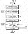
- FIG. 18 is a flowchart of the wireless communication method according to the sixth embodiment.
- the base station measures the wireless communication state between the base station and each mobile station.
- the base station compares each wireless communication state with a preliminarily set threshold, and for example, as a mobile station candidate for which amplification is to be performed at a relay station, extracts a mobile station for which the wireless communication state does not exceed the threshold (step S51).
- the base station determines the gain factor corresponding to the number of mobile stations requiring amplification (step S52).
- the processes hereinafter are identical to steps S43 to S47 in the fifth embodiment (steps S53 to S57).
- the execution timing of step S54 may be after step S53, before step S53, before step S52, or before step S51.
- the sixth embodiment effects identical to those of the first embodiment are obtained. Further, control that takes the number of mobile stations requiring amplification into consideration becomes possible where the gain factor is reduced when the number of mobile stations requiring amplification is large and the gain factor is reduced when the number of mobile stations requiring amplification is small.
- configuration may be such that as in the third embodiment, the list of nearby mobile stations is shared with other relay stations.
- a seventh embodiment incorporates into the second embodiment, a changing of the number of mobile stations judged to require amplification, where based on the interference power within the cell, the base station changes the threshold used for judging the wireless communication state, thereby changing the number of mobile stations.
- Configuration of the base station in the seventh embodiment is, for example, as depicted in FIG. 19 .
- Configuration the relay station in the seventh embodiment is identical to the second embodiment.
- FIG. 19 is a block diagram of the base station according to the seventh embodiment.
- FIG. 20 is a table depicting an example of relations between interference power and thresholds for judging the wireless communication state, in the seventh embodiment.
- a base station 81 includes a first measurer 82, a second measurer 83, a calculator 84, the judger 14, the generator 15, and the switch 17.
- the first measurer 82 is identical to the measurer 12 of the second embodiment.
- the second measurer 83 is identical to the second measurer 44 of the fourth embodiment.
- the calculator 84 calculates a threshold to be used for judging the wireless communication state.
- the relation between the interference power within the cell and the threshold used for judging the wireless communication state may be preliminarily determined by simulation using a computing device, for example.
- the judger 14 compares the threshold calculated by the calculator 84 and the wireless communication state of the mobile station, and judges whether the mobile station requires amplification.
- Other aspects of the base station 81 are identical to the second embodiment.
- I0, I1, I2, and I3 are numerical values indicating interference power and the relative magnitudes thereof, for example, are IO ⁇ II ⁇ I2 ⁇ I3.
- k, m, and n are numerical values indicating the thresholds used to judge the wireless communication state and the relative magnitudes thereof, for example, are k>m>n.
- FIG. 21 is a flowchart of the wireless communication method according to the seventh embodiment.
- the base station measures the wireless communication state between the base station and each mobile station (step S61).
- the base station measures the interference power within the cell and based on a preliminarily set correspondence relation, determines a threshold for judging the wireless communication state, corresponding to the interference power within the cell (step S62).
- the processes hereinafter are identical to steps S12 to S16 in the second embodiment (steps S63 to S67).
- the execution timing of step S64 may be after step S63, before step S63, before step S62, or before step S61.
- the seventh embodiment effects identical to those of the first embodiment are obtained. Further, when the interference power within the cell is great, the threshold for judging the wireless communication state is reduced and consequently, at the base station, the number of mobile stations judged to have a favorable wireless communication state increases. In other words, the number of mobile stations requiring amplification at a relay station decreases. On the other hand, when the interference power within the cell is small, the threshold for judging the wireless communication state is increased and consequently, at base station, the number of mobile stations judged to have a favorable wireless communication state decreases and the number of mobile stations requiring amplification at a relay station increases. In this manner, control that takes interference power within the cell into consideration can be performed.
- configuration may be such that as in the third embodiment, the list of nearby mobile stations is shared with other relays stations.
- An eighth embodiment incorporates in to the second embodiment, a changing of the number of mobile stations that are judged to be nearby, where the base station measures the interference power within the cell and the relay station changes based on the interference power within the cell, the threshold that is used to judge the wireless communication state, thereby changing the number of mobile stations that are judged to be nearby.
- Configuration of the base station in the eighth embodiment is, for example, as depicted in FIG. 22 .
- Configuration of the relay station in the eighth embodiment is, for example, as depicted in FIG. 23 .
- FIG. 22 is a block diagram of a configuration of the base station according to the eighth embodiment.
- a base station 91 includes a first measurer 92, a second measurer 93, the table 13, the judger 14, the generator 15, and the switch 17.
- the first measurer 92 is identical to the measurer 12 of the second embodiment.
- the second measurer 93 measures the interference power within the cell. Via the switch 17 and the antenna 16, interference power information is reported together with a list of mobile stations judged to require amplification.
- Other aspects of the base station 91 are identical to the second embodiment.
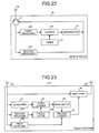
- FIG. 23 is a block diagram of the relay station according to the eighth embodiment.
- a relay station 101 includes a first receiver 102, a second receiver 103, a calculator 104, the measurer 22, the first judger 24, the generator 25, the second judger 27, and the amplifier 28.
- the first receiver 102 is identical to the receiver 26 of the second embodiment.
- the second receiver 103 receives and stores interference power information that is reported by base station and concerns the interference power within the cell.
- the calculator 104 calculates based on the interference power within the cell, a threshold to be used for judging the wireless communication state. The relation between the interference power within the cell and the threshold used for judging the wireless communication state may be preliminarily determined by simulation using a computing device, for example.
- the relation between the interference power within the cell and the threshold used for judging the wireless communication state may be identical to the table 85 depicted in FIG. 20 .
- the relative magnitudes of k, m, and n, which indicate thresholds for judging the wireless communication state are opposite to that of the seventh embodiment.
- the first judger 24 compares the threshold calculated by the calculator 104 and the wireless communication state of the mobile station, and for example, judges a mobile station to be nearby if the wireless communication state thereof exceeds the threshold.
- Other aspects of the relay station 101 are identical to the second embodiment.
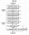
- FIG. 24 is a flowchart of the wireless communication method according to the eighth embodiment.
- the base station measures the wireless communication state between the base station and each mobile station, compares each wireless communication state with a threshold, and extracts a mobile station candidate for which amplification is to be performed at a relay station (step S71).
- the base station measure the interference power within the cell (step S72).
- the base station Based on the mobile station candidates for which amplification is to be performed at a relay station, the base station generates a list of mobile base stations that require amplification, and reports the list and information concerning the interference power within the cell (step S73).
- the relay station calculates a threshold for judging the wireless communication state, based on the interference power within the cell (step S74).
- the relay station measures the wireless communication state between the relay station and each mobile station, compares each wireless communication state with the threshold, and for example, judges a mobile station to be nearby if the wireless communication state thereof exceeds the threshold. In other words, the relay station generates a list of mobile stations that are nearby based on the calculated threshold (step S75).
- the processes hereinafter are identical to steps S14 to S16 in the second embodiment (step S76 to S78).In this series of processes, step S72 may be executed prior to step S71.
- the eighth embodiment effects identical to those of the first embodiment are obtained. Further, when the interference power within the cell is great, the threshold for judging the wireless communication state is increased, and consequently at the relay station, the number of mobile stations judged to have a favorable wireless communication state decreases. In other words, since the number of mobile stations that the relay station judges to be nearby decreases, the overall number of mobile stations for which amplification is to be performed, decreases. On the other hand, when the interference power within the cell is weak, the threshold for judging the wireless communication state is decreased, and consequently at relay station, the number of mobile stations judged to have a favorable wireless communication state increases.
- configuration may be such that as in the third embodiment, the list of nearby mobile stations is shared with other relay stations.
- a ninth embodiment incorporates into the second embodiment, a changing of the number of mobile stations that the relay station judges to be nearby based on a threshold that is generated by the base station, where the base station measures the interference power within the cell to generate the threshold used at the relay station to judge the wireless communication state.
- Configuration of the base station in the ninth embodiment is, for example, as depicted in FIG. 25 .
- Configuration of the relay station in the ninth embodiment is, for example, as depicted in FIG. 26 .
- FIG. 25 is a block diagram of the base station according to the ninth embodiment.
- a base station 111 includes a first measurer 112, a first generator 113, a second measurer 114, a second generator 115, the table 13, the judger 14, and the switch 17.
- the first measurer 112 and the first generator 113 are respectively identical to the measurer 12 and the generator 15 of the second embodiment.
- the second measurer 114 measures the interference power within the cell. Based on the interference power within the cell, the second generator 115 generates a threshold that is used at the relay station, to judge the wireless communication state. Via the switch 17 and the antenna 16, the threshold used at the relay station, to judge the wireless communication state is reported together with the list of mobile stations that require amplification.
- Other aspects of the base station 111 are identical to the second embodiment.
- FIG. 26 is a block diagram of a configuration of the relay station according to the ninth embodiment.
- a relay station 121 includes a first receiver 122, a second receiver 123, the measurer 22, the first judger 24, the generator 25, the second judger 27, and the amplifier 28.
- the first receiver 122 is identical to the receiver 26 of the second embodiment.
- the second receiver 123 receives and stores the threshold that is reported by base station and used at the relay station for judging the wireless communication state.
- the first judger 24 compares the threshold stored by the second receiver 123 and the wireless communication state of the mobile station, and for example, judges a mobile station to be nearby if the wireless communication state thereof exceeds the threshold.
- Other aspects of the relay station 121 are identical to the second embodiment.
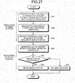
- FIG. 27 is a flowchart of the wireless communication method according to the ninth embodiment.
- the base station measures the wireless communication state between the base station and each mobile station, compares each wireless communication state with a threshold, and extracts a mobile station candidate for which amplification is to be performed at a relay station (step S81).
- the base station measures the interference power within the cell, and based on the interference power within the cell, determines a threshold to be used the judge the wireless communication state, at the relay station (step S82).
- the base station Based on the mobile station candidates for which amplification is to be performed at the relay station, the base station generates a list of mobile stations requiring amplification, and reports the list and the threshold to be used at the relay station, to judge the wireless communication state (step S83).
- the relay station measures the wireless communication state between the relay station and each mobile station, compares each wireless communication state with the threshold, and for example, judges a mobile station to be nearby if the wireless communication state thereof exceeds the threshold. In other words, the relay station generates a list of nearby mobile stations base station, based on the generated threshold (step S84).
- the processes thereinafter are identical to steps S14 to S16 in the second embodiment (steps S85 to S87). In this series of processes, step S82 may be executed prior to step S81.
- the ninth embodiment effects identical to those of the first embodiment are obtained. Further, similar to the eighth embodiment, control that takes interference power within the cell into consideration, can be performed. In the ninth embodiment, as in the third embodiment, the list of nearby mobile stations may be shared with other relay stations.
Landscapes
- Engineering & Computer Science (AREA)
- Computer Networks & Wireless Communication (AREA)
- Signal Processing (AREA)
- Mobile Radio Communication Systems (AREA)
- Radio Relay Systems (AREA)
Abstract
Description
- The present invention relates to a base station, a relay station, a wireless communication system, and a wireless communication method.
- A relay station is conventionally used in wireless communication systems. Relay stations include non-regenerating types that amplify and transmit received signals, and regenerating types that amplify and transmit received signals after first decoding the signal and regenerating the original data. Among mobile communication systems, a system is known that can determine communication paths capable of realizing high speed communication by multi-hop. For example, a mobile communication system includes a communication path determining unit that based on the interference level of the signals respectively received by a relay station and a base station, which form a communication path between communicating stations, determines a communication path that offers the fastest communication speed or that satisfies a specified line quality (see, for example, Patent document 1). Further, a system is known that increases the effective area of a spread spectrum-based wireless network as well as communication capacity. For example, the system has a wireless communication network that is expanded by a low-cost, channel selector-type relay apparatus capable of relaying desired signals alone (see, for example, Patent document 2).
-
- Patent document 1: International Publication Pamphlet No.
2003/101132 - Patent document 2: Published Japanese-Translation of PCT Application, Publication No.
2006-501759 - With conventional regenerating type relay stations, since signals subject to amplification can be controlled according to user, the source of interference can be controlled. However, since the decoding process takes time, regenerating type relay stations have a problem in that a greater delay occurs that with non-regenerating type relay station. Meanwhile, with conventional non-regenerating type relay stations a problem arises in that since amplification is performed at a constant gain factor, the relay station may become a source of interference.
- An object of the disclosed wireless communication system and wireless communication method is to provide a system and a method that can prevent the relay station from becoming a source of interference. Another object of the disclosed base station and relay station is to provide a base station and a relay station that can implement a system capable of preventing the relay station from becoming a source of interference.
- The wireless communication system includes a base station and a relay station. The base station includes a selector and a reporter. Based on the wireless communication state with each mobile station, the selector selects a mobile station that requires amplification at the relay station. The reporter reports first information related to the mobile station selected by the selector. The relay station includes a selector and an amplifier. At the relay station, the selector selects based on the wireless communication state with each mobile, a mobile station candidate for which amplification is to be performed station. The amplifier performs amplification, based on second information related to the mobile station candidate selected by the selector and the first information reported by the base station.
- According to the disclosed base station, relay station, wireless communication system, and wireless communication method, a relay station can prevented from becoming a source of interference.
-
-
FIG. 1 is a block diagram of a configuration of a wireless communication system according to a first embodiment; -
FIG. 2 is a flowchart of a wireless communication method according to the first embodiment; -
FIG. 3 is a block diagram of a configuration of a base station according to a second embodiment; -
FIG. 4 is a block diagram of a configuration of a relay station according to the second embodiment; -
FIG. 5 is a flowchart of the wireless communication method according to the second embodiment; -
FIG. 6 is a block diagram of a configuration of the relay station according to a third embodiment; -
FIG. 7 is a flowchart of the wireless communication method according to the third embodiment; -
FIG. 8 is a diagram of an example of wireless communication states between the relay station and the mobile station in the third embodiment; -
FIG. 9 is a block diagram of a configuration of the base station according to a fourth embodiment; -
FIG. 10 is a table depicting an example of a second table; -
FIG. 11 is a flowchart of the wireless communication method according to the fourth embodiment; -
FIG. 12 is a block diagram of a configuration of the base station according to a fifth embodiment; -
FIG. 13 is a table depicting an example of the second table; -
FIG. 14 is a block diagram of the relay station according to the fifth embodiment; -
FIG. 15 is a flowchart of the wireless communication method according to the fifth embodiment; -
FIG. 16 is a block diagram of the base station according to a sixth embodiment; -
FIG. 17 is a diagram depicting an example of the second table; -
FIG. 18 is a flowchart of the wireless communication method according to the sixth embodiment; -
FIG. 19 is a block diagram of the base station according to a seventh embodiment; -
FIG. 20 is a table depicting an example of relations between interference power and thresholds for judging the wireless communication state, in the seventh embodiment; -
FIG. 21 is a flowchart of the wireless communication method according to the seventh embodiment; -
FIG. 22 is a block diagram of a configuration of the base station according to an eighth embodiment; -
FIG. 23 is a block diagram of the relay station according to the eighth embodiment; -
FIG. 24 is a flowchart of the wireless communication method according to the eighth embodiment; -
FIG. 25 is a block diagram of the base station according to a ninth embodiment; -
FIG. 26 is a block diagram of a configuration of the relay station according to the ninth embodiment; and -
FIG. 27 is a flowchart of the wireless communication method according to the ninth embodiment. - With reference to the accompanying drawings, embodiments of a base station, a relay station, a wireless communication system, and a wireless communication method according to the present invention will be described in detail below. In the description of the embodiments, identical components are given the same reference numeral and overlapping description is omitted. Furthermore, the present invention is not limited by the following embodiments.
- In a first embodiment, the base station selects based on the wireless communication state with each mobile station, a mobile station that requires amplification by the relay station; and reports first information related to the selected mobile station. The relay station selects, based on the wireless communication state with each mobile station, a mobile station candidate for which amplification is to be performed; and performs amplification, based on second information related to the selected mobile station candidate and the first information reported by the base station.
-
FIG. 1 is a block diagram of a configuration of the wireless communication system according to the first embodiment. As depicted inFIG. 1 , the wireless communication system includes abase station 1 and arelay station 2. Thebase station 1 includes aselector 3 and areporter 4. Theselector 3 selects based on the wireless communication state between thebase station 1 and amobile station 7, a mobile station for which amplification is to be performed at therelay station 2. Thereporter 4 reports first information related to the mobile station selected by theselector 3. Therelay station 2 includes aselector 5 and anamplifier 6. Theselector 5 of therelay station 2 selects based on the wireless communication state between therelay station 2 and themobile station 7, a mobile station candidate for which amplification is to be performed. Theamplifier 6 performs amplification, based on second information related to the mobile station candidate selected by theselector 5 of therelay station 2 and the first information reported by thebase station 1. The number of therelay stations 2 and/or the number of themobile stations 7 may be plural. -
FIG. 2 is a flowchart of the wireless communication method according to the first embodiment. As depicted inFIG. 2 , when a process begins for determining whether amplification is to be performed during wireless communication between a base station and a mobile station, the base station selects based on the wireless communication state with the mobile station, a mobile station for which amplification is to be performed at the relay station (step S1). The base station reports information (first information) related to the mobile station selected at step S1 (step S2). Meanwhile, the relay station selects based on the wireless communication state with the mobile station, a mobile station candidate for which amplification is to be performed (step S3). The relay station performs amplification, based on information (second information) related to the mobile station candidate selected at step S3 and the first information reported by the base station at step S2 (step S4). In this series of processes, step S1 and step S2 are executed in this sequence. Step S4 is executed after steps S1, S2, and S3. The execution timing of step S3 may be after step S2, before step S2, or before step S1. - According to the first embodiment, the relay station performs amplification based on information concerning a mobile station that has been selected by the base station, for amplification, and information concerning a mobile station that is regarded as a candidate for amplification by the relay station, thereby enabling configuration to be such that the relay station does not perform amplification when the mobile station regarded as the candidate for amplification by the relay station is not included in the information concerning the mobile station that has been selected by the base station, for amplification. If the radio wave environment around the relay station changes while the relay station is performing amplification and the mobile station that is regarded as the candidate for amplification by the relay station is no longer included in the information concerning the mobile station selected by the base station, the relay station can terminate the amplification. Consequently, the phenomenon of the relay station becoming a source of interference, consequent to the relay station performing amplification when amplification is not necessary, can be prevented. When the base station selects plural mobile stations to be subject to amplification and plural relay stations are present, the respective relay stations perform amplification if the amplification candidate thereof is included in the information concerning the mobile stations selected by the base station. Consequently, the mobile stations requiring amplification are distributed among the relay stations, enabling amplification to be performed efficiently.
-
FIG. 3 is a block diagram of a configuration of the base station according to a second embodiment. As depicted inFIG. 3 , abase station 11 includes ameasurer 12, a table 13, ajudger 14, and agenerator 15. Via anantenna 16 and aswitch 17, thebase station 11 receives a wireless signal transmitted from a non-depicted mobile station. Themeasurer 12 measures the wireless communication state between thebase station 11 and the mobile station. Reception quality (signal to interference power ratio (SIR)) is one example of a wireless communication state. In this case, for example, themeasurer 12 measures the reception quality (SIR) of a common pilot channel between the base station and the mobile station. The table 13 stores thresholds used when the wireless communication state is judged. - The
judger 14 compares the wireless communication state and a threshold. Thejudger 14, for example, judges that amplification is not necessary for a mobile station for which the wireless communication state exceeds or is equal to the threshold. The wireless signal between the base station and a mobile station, for which amplification is judged to be not necessary, is not amplified at a relay station (not depicted). Thejudger 14, for example, judges that amplification is necessary for a mobile station for which the wireless communication state is less than the threshold. The wireless signal between the base station and a mobile station for which amplification is judged to be necessary is amplified at a non-depicted relay station. Thegenerator 15 generates a list of mobile stations for which amplification has been judged to be necessary. Thebase station 11 reports (broadcasts), via theswitch 17 and theantenna 16, the list of mobile stations for which amplification has been judged necessary. - The
antenna 16, theswitch 17, themeasurer 12, the table 13, and thejudger 14, for example, operate as theselector 3 of thebase station 1 in the first embodiment. Thegenerator 15, theswitch 17, and theantenna 16, for example, operate as thereporter 4 in the first embodiment. The list of mobile stations for which amplification has been judged to be necessary is one example of the first information in the first embodiment. -
FIG. 4 is a block diagram of a configuration of the relay station according to the second embodiment. As depicted inFIG. 4 , arelay station 21 is a non-regenerating type relay apparatus, for example. Therelay station 21 includes ameasurer 22, a table 23, afirst judger 24, agenerator 25, areceiver 26, asecond judger 27, and anamplifier 28. Via anantenna 29, therelay station 21 receives a wireless signal transmitted from a non-depicted base station or mobile station. Themeasurer 22 measures the wireless communication state between therelay station 21 and the mobile station. An example of the wireless communication state is reception quality (SIR). In this case, for example, themeasurer 22 measures the reception quality (SIR) of a common pilot channel between the base station and the mobile station. The table 23 stores thresholds used when the wireless communication state is judged. - The
first judger 24 compares the wireless communication state and a threshold. In general, the nearer the mobile station is to therelay station 21, the better the wireless communication state. Thefirst judger 24, for example, judges a mobile station to be nearby if the wireless communication state thereof exceeds the threshold. A mobile station judged to be nearby is a mobile station candidate for which amplification is to be performed by therelay station 21. Thefirst judger 24, for example, judges a mobile station to not be nearby if the wireless communication state thereof is less than or equal to the threshold. A mobile station judged to not be nearby is not a mobile station candidate for which amplification is to be performed by therelay station 21. Thegenerator 25 generates a list of mobile station candidates for which amplification is to be performed by therelay station 21. Thereceiver 26 receives and stores the list of mobile stations reported and judged by the base station to require amplification. - The
second judger 27 judges whether to perform amplification at therelay station 21, based on the list of mobile station candidates for which amplification is to be performed and the list of mobile stations judged to require amplification. For example, thesecond judger 27 judges that amplification is to be performed by therelay station 21, when one or more of the mobile stations included on the list of mobile station candidates for which amplification is to be performed at therelay station 21 is included on the list of mobile stations judged to require amplification. Theamplifier 28 switches between states of performing amplification operations and not performing amplification operations, based on the judgment results of thesecond judger 27. When amplification operations are performed by theamplifier 28, a received signal is amplified by theamplifier 28 and the amplified signal is transmitted via anantenna 30. - The
antenna 29, themeasurer 22, the table 23, and thefirst judger 24, for example, operate as theselector 5 of therelay station 2 in the first embodiment. Thegenerator 25, thereceiver 26, thesecond judger 27, and theamplifier 28, for example, operate as theamplifier 6 in the first embodiment. The list of mobile station candidates for which therelay station 21 is to perform amplification is an example of the second information in the first embodiment. -
FIG. 5 is a flowchart of the wireless communication method according to the second embodiment. As depicted in F`IG. 5, when a process begins for determining whether amplification is to be performed during wireless communication between a base station and a mobile station, the relay station is in a state of not performing amplification and base station measures the wireless communication state between the base station and the mobile station (step S11). For example, the base station measures the reception quality (SIR) of a common pilot channel between the base station and the mobile station. The base station compares the wireless communication state and a preliminarily set threshold, and for example, judges that amplification is necessary for a mobile station for which the wireless communication state does not exceed the threshold. The base station generates a list of mobile stations requiring amplification and reports the list (step S12). - Meanwhile the relay station measures the wireless communication state between the relay station and the mobile station. For example, the relay station measures the reception quality (SIR) of a common pilot channel between the base station and the mobile station. The relay station compares the wireless communication state and a preliminarily set threshold and for example, judges a mobile station to be nearby if the wireless communication state thereof exceeds the threshold. The relay station generates a list of mobile stations that have been judged to be nearby (a nearby-mobile-station list) (step S13).
The relay station checks whether the mobile stations judged to be nearby are included on the list of mobile stations reported and judged by the base station to require amplification. The relay station judges that amplification is necessary if the mobile stations judged to be nearby are included on the list of mobile stations judged to require amplification, whereas if the mobile stations are not included, the relay station judges that amplification is not necessary (step S14). If the judgment result is that amplification is necessary (step S14: YES), the relay station begins amplification (step S15). If amplification is judged to not be necessary (step S14: NO), the relay station remains in a state of not performing amplification (step S16). - The base station continuously measures the wireless communication state between the base station and the mobile stations, generates a list of mobile stations requiring amplification, and reports the list. The relay station continuously measures the wireless communication state between the relay station and the mobile stations, and generates a list of mobile stations judged to be nearby. In other words, the list of mobile stations judged at the base station, to require amplification and the list of mobile stations judged at the relay station, to be nearby dynamically change. The relay station terminates amplification when the mobile station judged to be nearby ceases to be included on the list of mobile stations judged to require amplification. When there are plural relay stations within transmission range of the base station, such as in a cell or sector created by the base station, steps S13 to S16 are executed at each relay station. In this series of processes, steps S11 and S12 are executed in this sequence. Step S14 is executed after steps S11, S12, and S13. The execution timing of step S13 may be after step S12, before step S12, or before step 511.
- According to the second embodiment, effects identical to those of the first embodiment are obtained. If the same mobile station is included in the nearby-mobile-station list of plural relay stations, amplification for the mobile station may be performed by the plural relay stations. Further, a regenerating type relay station may be used as the relay station.
- A third embodiment incorporates into the second embodiment, a sharing of the nearby-mobile-station lists among the relay stations. Configuration of the base station in the third embodiment is identical to that in the second embodiment. Configuration of the relay station in third embodiment is as depicted in
FIG. 6 , for example. -
FIG. 6 is a block diagram of a configuration of the relay station according to the third embodiment. As depicted inFIG. 6 , arelay station 31 includes afirst receiver 32, asecond receiver 33, acontroller 34, themeasurer 22, the table 23, thefirst judger 24, thegenerator 25, thesecond judger 27, and theamplifier 28. Thefirst receiver 32 is identical to thereceiver 26 of the second embodiment. Thesecond receiver 33 receives and stores the nearby-mobile-station lists from other relay stations. Thecontroller 34 generates a wireless channel for transmitting the nearby-mobile-station list of therelay station 31 to other relay stations. Thecontroller 34 controls the wireless channel and transmits the nearby-mobile-station list of therelay station 31 to other relay stations, via theantenna 30. - The
second judger 27 judges whether amplification at therelay station 31 is to be performed, based on the list of mobile station candidates for which amplification is to be performed at therelay station 31, the list of mobile stations judged to require amplification, and the nearby-mobile-station lists of other relay stations. For example, when the following two conditions are satisfied, thesecond judger 27 judges that amplification at therelay station 31 is to be performed. A first condition is that one or more mobile stations included on the list of mobile station candidates for which amplification is to be performed at therelay station 31, is included on the list of mobile stations judged to require amplification. A second condition is that a mobile station that is included in both the list of mobile station candidates for which amplification is to be performed at therelay station 31 and the list of mobile stations judged to require amplification, is located nearer to therelay station 31 than to other relay stations. Thesecond judger 27 judges that amplification is not to be performed by therelay station 31, when none of the mobile stations included on the list of mobile station candidates for which amplification is to be performed at therelay station 31 are included on the list of mobile stations judged to require amplification, or when the first condition is satisfied, but the second condition is not. Other aspects of therelay station 31 are identical to the second embodiment. -
FIG. 7 is a flowchart of the wireless communication method according to the third embodiment. As depicted inFIG. 7 , when the processes begin, similar to steps S11 to S13 in the second embodiment, the base station measures the wireless communication state between the base station and the mobile station (step S21), generates a list of mobile station that have been judged to require amplification, and reports the list (step S22). Meanwhile, each relay station generates a list of nearby mobile stations (step S23). The relay stations transmit and receive the lists of nearby mobile stations with one another and thereby share the lists (step S24). - Similar to step S14 of the first embodiment, each relay station, judges whether amplification is necessary (step S25). If the judgment result is that amplification is necessary (step S25: YES), the relay station judges whether a mobile station that is included in both the list of mobile station candidates for which amplification is to be performed by the relay station and the list of mobile stations judged to require amplification, is located nearer to the relay station than to other relay stations (step S26). If so (step S26: YES), the relay station begins amplification (step S27). At step S25, if amplification is not necessary (step S25: NO), or at step S26, if the mobile station is nearer to another relay station (step S26: NO), the relay station remains in a state of not performing amplification (step S28). In this series of processes, the execution timing of step S23 may be after step S22, before step S22, or before step S21.
-
FIG. 8 is a diagram of an example of wireless communication states between the relay station and the mobile station in the third embodiment. For example, the wireless communication system is assumed to include relay station A and relay station B in addition to the base station, where mobile station A, mobile station B, and mobile station C are located in a vicinity of relay station A and relay station B. At each relay station, the wireless communication state (reception quality, SIR) of each mobile station is assumed to be as depicted in table 35 inFIG. 8 . At each relay station, the threshold when judging whether a mobile station is nearby, is assumed to be 5dB. In this example, for relay station A, mobile station B is included on the list of mobile stations that have been judge to be nearby. For relay station B, mobile station B and mobile station A are included on the list of mobile stations that have been judged to be nearby. Mobile station B is assumed to be included on the list of mobile stations that have been reported and judged by the base station to require amplification. According toFIG. 8 , the reception quality of mobile station B is better for relay station A than for relay station B and accordingly, at step S26 in the flowchart depicted inFIG. 7 , mobile station B is judged to be located nearer to relay station A than to relay station B. Therefore, relay station A begins amplification (step S27), and relay station B remains in a state of not performing amplification (step S28). At relay station B, although the reception quality of mobile station A is favorable, for example, if mobile station A is not included in the list of mobile stations reported and judged by the base station to require amplification, the judgment of whether amplification is necessary is not performed with respect to mobile station A. - According to the third embodiment, effects identical to those of the first embodiment are obtained. Further, configuration may be such that a relay station transmits the list of nearby mobile stations to another relay station by a wired line.
- A fourth embodiment incorporates into the second embodiment, a changing of the number of mobile stations judged to require amplification, based on interference power within the cell The configuration of the base station in the fourth embodiment is, for example, as depicted in
FIG. 9 . The configuration of the relay station in the fourth embodiment is identical to that in the second embodiment. -
FIG. 9 is a block diagram of a configuration of the base station according to the fourth embodiment.FIG. 10 is a table depicting an example of a second table. As depicted inFIG. 9 , abase station 41 includes afirst measurer 42, a first table 43, asecond measurer 44, a second table 45, acalculator 46, thejudger 14, thegenerator 15, and theswitch 17. Thefirst measurer 42 and the first table 43 are respectively identical to themeasurer 12 and the table 13 of the second embodiment. Thesecond measurer 44 measures the interference power within the cell. The second table 45 stores correspondence relations between the interference power within the cell and the number of amplifiable mobile stations (seeFIG. 10 ). Correspondence relations between the interference power within the cell and the number of amplifiable mobile stations may be preliminarily determined by simulation using a computing device, for example. Thecalculator 46 determines the number of mobile stations that can be amplified, based on the correspondence relation between the interference power within the cell and the number of amplifiable mobile stations, and the interference power within the cell. Using the number of amplifiable mobile stations as an upper limit, thegenerator 15 generates a list of mobile stations judged to require amplification. Other aspects of thebase station 41 are identical to the second embodiment. InFIG. 10, 10 ,11 ,12, and 13 are numerical values indicating interference power and the relative magnitudes thereof, for example, are 10<Il<12<13. Further, a, b, and c areintegers 0 or greater indicating the number of mobile stations and the relative magnitudes thereof, for example, are a>b>c. -
FIG. 11 is a flowchart of the wireless communication method according to the fourth embodiment. As depicted inFIG. 11 , when the processes begin, the base station measures the wireless communication state between the base station and each mobile station. The base station compares each wireless communication state with a preliminarily set threshold, and for example, as a mobile station candidate for which amplification is to be performed at a relay station, extracts a mobile station for which the wireless communication state does not exceed the threshold (step S31). The base station measures the interference power within the cell and based on a preliminarily set correspondence relation, determines the number of amplifiable mobile stations corresponding to the interference power in within the cell (step S32). Using the number of amplifiable mobile stations as an upper limit, the base station extracts, for example, in descending order of poor wireless communication state and from among the mobile station candidates to be amplified at a relay station, mobile stations requiring amplification. The base station generates and reports a list of mobile stations requiring amplification (step S33). - Meanwhile, each relay station, as at steps S13 to S16 in the second embodiment, after generating a list of nearby mobile stations (step S34), judges whether amplification is necessary (step S35). Based on the judgment results, the relay station begins amplification (step S36), or remains in a state of not performing amplification (step S37). In this series of processes, step S32 may be executed prior to step S31. The execution timing of step S34 may be after step S33, before step S33, before step S32, or before step S31.
- According to the fourth embodiment, effects identical to those of the first embodiment are obtained. Further, control that takes interference power in the cell into consideration become possible where the number of mobile stations for which amplification is to be performed at the relay station is reduced when the interference power within the cell is great, and the number of mobile stations for which amplification is to be performed at the relay station is increased when the interference power within the cell is low. In the fourth embodiment, configuration may be such that as in the third embodiment, the list of nearby mobile stations is shared with other relay stations.
- A fifth embodiment incorporates into the second embodiment, a changing of the gain factor at the relay station, based on interference power within the cell. Configuration of the base station in the fifth embodiment is, for example, as depicted in
FIG. 12 . Configuration of the relay station in the fifth embodiment is, for example, as depicted inFIG. 14 . -
FIG. 12 is a block diagram of a configuration of the base station according to the fifth embodiment.FIG. 13 is a table depicting an example of the second table. As depicted inFIG. 12 , abase station 51 includes afirst measurer 52, a first table 53, asecond measurer 54, a second table 55, acalculator 56, thejudger 14, thegenerator 15, and theswitch 17. Thefirst measurer 52 and the first table 53 are respectively identical to themeasurer 12 and the table 13 of the second embodiment. Thesecond measurer 54 measures the interference power within the cell. The second table 55 stores correspondence relations between the interference power within the cell and gain factor (seeFIG. 13 ). Correspondence relations between interference power within the cell and gain factor may be preliminarily determined by simulation using a computing device, for example. Thecalculator 56 determines the gain factor, based on the correspondence relation between the interference power within the cell and gain factor, and the interference power within the cell. Via theswitch 17 and theantenna 16, gain factor information is reported, together with the list of mobile stations that have been judged to require amplification. Other aspects of thebase station 51 are identical to the second embodiment. InFIG. 13 , I0, I1, I2, and I3 are numerical values indicating interference power and the relative magnitudes thereof, for example, are I0<Il<I2<I3. Further, d, e, and f are numerical values indicating gain factors and the relative magnitudes thereof, for example, are d>e>f. -
FIG. 14 is a block diagram of the relay station according to the fifth embodiment. As depicted inFIG. 14 , arelay station 61 includes afirst receiver 62, asecond receiver 63, themeasurer 22, the table 23, thefirst judger 24, thegenerator 25, thesecond judger 27, and theamplifier 28. Thefirst receiver 62 is identical to thereceiver 26 of the second embodiment. Thesecond receiver 63 receives and stores gain factor information reported by the base station. Thesecond judger 27 controls the gain factor, based on the gain factor information reported by the base station, when amplification is judged to be performed. Other aspects of therelay station 61 are identical to the second embodiment. -
FIG. 15 is a flowchart of the wireless communication method according to the fifth embodiment. As depicted inFIG. 15 , when the processes begin, the base station measures the wireless communication state between the base station and each mobile station. The base station compares each wireless communication state with a preliminarily set threshold, and for example, as a mobile station candidate for which amplification is to be performed at a relay station, extracts a mobile station for which the wireless communication state does not exceed the threshold (step S41). The base station measures the interference power within the cell and based on a preliminarily set correspondence relation, determines the gain factor corresponding to the interference power within the cell (step S42). The base station generates based on mobile station candidates for which amplification is to be performed at a relay station, a list of mobile stations requiring amplification, and reports the list and the gain factor (step S43). - Meanwhile, each relay station, as at steps S13 to S16 in the second embodiment, after generating the list of nearby mobile stations (step S44), judges whether amplification is necessary (step S45). Based on the judgment results, the relay station begins amplification (step S46), or remains in a state of not performing amplification (step S47). If the relay station begins amplification, the relay station uses the gain factor reported by the base station. In this series of processes, step S42 may be executed prior to step S41. The execution timing of step S44 may be after step S43, before step S43, before step S42, or before step S41.
- According to the fifth embodiment, effects identical to those of the first embodiment are obtained. Further, control that takes interference power within the cell into consideration becomes possible where the gain factor is reduced when the interference power within the cell is great, and the gain factor is increased when the interference power within the cell is low. In the fifth embodiment, configuration may be such that as in the third embodiment, the list of nearby mobile stations is shared with other relay stations.
- A sixth embodiment incorporates into the second embodiment, a changing of the gain factor at a relay station, based on the number of mobile stations that require amplification. Configuration of the base station in the sixth embodiment is, for example, as depicted in
FIG. 16 . Configuration of the relay station in the sixth embodiment is identical to the fifth embodiment. -
FIG. 16 is a block diagram of the base station according to the sixth embodiment.FIG. 17 is a diagram depicting an example of the second table. As depicted inFIG. 16 , abase station 71 includes a first table 72, a second table 73, acalculator 74, themeasurer 12, thejudger 14, thegenerator 15, and theswitch 17. The first table 72 is identical to the table 13 of the second embodiment. The second table 73 stores correspondence relations between the number of mobile stations requiring amplification and the gain factor (seeFIG. 17 ). Correspondence relations between the number of mobile stations requiring amplification and the gain factor may be preliminarily determined by simulation using a computing device, for example. Thecalculator 74 determines the gain factor, based on the correspondence relations between the number of mobile stations requiring amplification and the gain factor, and the number of mobile stations requiring amplification. Via theswitch 17 and theantenna 16, gain factor information is reported, together with the list of mobile stations judged to require amplification. Thegenerator 15 reports to thecalculator 74, the number of mobile stations that require amplification. Other aspects of thebase station 71 are identical to the second embodiment. InFIG. 17 , N0, N1, N2, and N3 are number of mobile stations requiring amplification and the relative magnitude thereof, for example, are NO<N1<N2<N3. Further, g, h, and j are numerical values indicating the gain factor and relative magnitudes thereof, for example, are g>h>j. -
FIG. 18 is a flowchart of the wireless communication method according to the sixth embodiment. As depicted inFIG. 18 , when the processes begin, the base station measures the wireless communication state between the base station and each mobile station. The base station compares each wireless communication state with a preliminarily set threshold, and for example, as a mobile station candidate for which amplification is to be performed at a relay station, extracts a mobile station for which the wireless communication state does not exceed the threshold (step S51). Based on a preliminarily set correspondence relation, the base station determines the gain factor corresponding to the number of mobile stations requiring amplification (step S52). The processes hereinafter are identical to steps S43 to S47 in the fifth embodiment (steps S53 to S57). In this series of processes, the execution timing of step S54 may be after step S53, before step S53, before step S52, or before step S51. - According to the sixth embodiment, effects identical to those of the first embodiment are obtained. Further, control that takes the number of mobile stations requiring amplification into consideration becomes possible where the gain factor is reduced when the number of mobile stations requiring amplification is large and the gain factor is reduced when the number of mobile stations requiring amplification is small. In the sixth embodiment, configuration may be such that as in the third embodiment, the list of nearby mobile stations is shared with other relay stations.
- A seventh embodiment incorporates into the second embodiment, a changing of the number of mobile stations judged to require amplification, where based on the interference power within the cell, the base station changes the threshold used for judging the wireless communication state, thereby changing the number of mobile stations. Configuration of the base station in the seventh embodiment is, for example, as depicted in
FIG. 19 . Configuration the relay station in the seventh embodiment is identical to the second embodiment. -
FIG. 19 is a block diagram of the base station according to the seventh embodiment.FIG. 20 is a table depicting an example of relations between interference power and thresholds for judging the wireless communication state, in the seventh embodiment. As depicted inFIG. 19 , abase station 81 includes afirst measurer 82, asecond measurer 83, acalculator 84, thejudger 14, thegenerator 15, and theswitch 17. Thefirst measurer 82 is identical to themeasurer 12 of the second embodiment. Thesecond measurer 83 is identical to thesecond measurer 44 of the fourth embodiment. Based on the interference power within the cell, thecalculator 84 calculates a threshold to be used for judging the wireless communication state. The relation between the interference power within the cell and the threshold used for judging the wireless communication state may be preliminarily determined by simulation using a computing device, for example. Thejudger 14 compares the threshold calculated by thecalculator 84 and the wireless communication state of the mobile station, and judges whether the mobile station requires amplification. Other aspects of thebase station 81 are identical to the second embodiment. In table 85 depicted inFIG. 20 , I0, I1, I2, and I3 are numerical values indicating interference power and the relative magnitudes thereof, for example, are IO<II<I2<I3. Further, k, m, and n are numerical values indicating the thresholds used to judge the wireless communication state and the relative magnitudes thereof, for example, are k>m>n. -
FIG. 21 is a flowchart of the wireless communication method according to the seventh embodiment. As depicted inFIG. 21 , when the processes begin, the base station measures the wireless communication state between the base station and each mobile station (step S61). The base station measures the interference power within the cell and based on a preliminarily set correspondence relation, determines a threshold for judging the wireless communication state, corresponding to the interference power within the cell (step S62). The processes hereinafter are identical to steps S12 to S16 in the second embodiment (steps S63 to S67). In this series of processes, the execution timing of step S64 may be after step S63, before step S63, before step S62, or before step S61. - According to the seventh embodiment, effects identical to those of the first embodiment are obtained. Further, when the interference power within the cell is great, the threshold for judging the wireless communication state is reduced and consequently, at the base station, the number of mobile stations judged to have a favorable wireless communication state increases. In other words, the number of mobile stations requiring amplification at a relay station decreases. On the other hand, when the interference power within the cell is small, the threshold for judging the wireless communication state is increased and consequently, at base station, the number of mobile stations judged to have a favorable wireless communication state decreases and the number of mobile stations requiring amplification at a relay station increases. In this manner, control that takes interference power within the cell into consideration can be performed. In the seventh embodiment, configuration may be such that as in the third embodiment, the list of nearby mobile stations is shared with other relays stations.
- An eighth embodiment incorporates in to the second embodiment, a changing of the number of mobile stations that are judged to be nearby, where the base station measures the interference power within the cell and the relay station changes based on the interference power within the cell, the threshold that is used to judge the wireless communication state, thereby changing the number of mobile stations that are judged to be nearby. Configuration of the base station in the eighth embodiment is, for example, as depicted in
FIG. 22 . Configuration of the relay station in the eighth embodiment is, for example, as depicted inFIG. 23 . -
FIG. 22 is a block diagram of a configuration of the base station according to the eighth embodiment. As depicted inFIG. 22 , abase station 91 includes afirst measurer 92, asecond measurer 93, the table 13, thejudger 14, thegenerator 15, and theswitch 17. Thefirst measurer 92 is identical to themeasurer 12 of the second embodiment. Thesecond measurer 93 measures the interference power within the cell. Via theswitch 17 and theantenna 16, interference power information is reported together with a list of mobile stations judged to require amplification. Other aspects of thebase station 91 are identical to the second embodiment. -
FIG. 23 is a block diagram of the relay station according to the eighth embodiment. As depicted inFIG. 23 , arelay station 101 includes afirst receiver 102, asecond receiver 103, acalculator 104, themeasurer 22, thefirst judger 24, thegenerator 25, thesecond judger 27, and theamplifier 28. Thefirst receiver 102 is identical to thereceiver 26 of the second embodiment. Thesecond receiver 103 receives and stores interference power information that is reported by base station and concerns the interference power within the cell. Thecalculator 104 calculates based on the interference power within the cell, a threshold to be used for judging the wireless communication state. The relation between the interference power within the cell and the threshold used for judging the wireless communication state may be preliminarily determined by simulation using a computing device, for example. The relation between the interference power within the cell and the threshold used for judging the wireless communication state, for example, may be identical to the table 85 depicted inFIG. 20 . However, in the eighth embodiment, in the table 85 depicted inFIG. 20 , the relative magnitudes of k, m, and n, which indicate thresholds for judging the wireless communication state are opposite to that of the seventh embodiment. Thefirst judger 24 compares the threshold calculated by thecalculator 104 and the wireless communication state of the mobile station, and for example, judges a mobile station to be nearby if the wireless communication state thereof exceeds the threshold. Other aspects of therelay station 101 are identical to the second embodiment. -
FIG. 24 is a flowchart of the wireless communication method according to the eighth embodiment. As depicted inFIG. 24 , when the processes begin, the base station measures the wireless communication state between the base station and each mobile station, compares each wireless communication state with a threshold, and extracts a mobile station candidate for which amplification is to be performed at a relay station (step S71). The base station measure the interference power within the cell (step S72). Based on the mobile station candidates for which amplification is to be performed at a relay station, the base station generates a list of mobile base stations that require amplification, and reports the list and information concerning the interference power within the cell (step S73). - The relay station calculates a threshold for judging the wireless communication state, based on the interference power within the cell (step S74). The relay station measures the wireless communication state between the relay station and each mobile station, compares each wireless communication state with the threshold, and for example, judges a mobile station to be nearby if the wireless communication state thereof exceeds the threshold. In other words, the relay station generates a list of mobile stations that are nearby based on the calculated threshold (step S75). The processes hereinafter are identical to steps S14 to S16 in the second embodiment (step S76 to S78).In this series of processes, step S72 may be executed prior to step S71.
- According to the eighth embodiment, effects identical to those of the first embodiment are obtained. Further, when the interference power within the cell is great, the threshold for judging the wireless communication state is increased, and consequently at the relay station, the number of mobile stations judged to have a favorable wireless communication state decreases. In other words, since the number of mobile stations that the relay station judges to be nearby decreases, the overall number of mobile stations for which amplification is to be performed, decreases. On the other hand, when the interference power within the cell is weak, the threshold for judging the wireless communication state is decreased, and consequently at relay station, the number of mobile stations judged to have a favorable wireless communication state increases.
In other words, since the number of relay stations that the relay station judges to be nearby increases, the overall number of mobile stations for which amplifications is to be performed, can be increased. In this manner, control can be performed that takes into consideration the interference power within the cell. In the eighth embodiment, configuration may be such that as in the third embodiment, the list of nearby mobile stations is shared with other relay stations. - A ninth embodiment incorporates into the second embodiment, a changing of the number of mobile stations that the relay station judges to be nearby based on a threshold that is generated by the base station, where the base station measures the interference power within the cell to generate the threshold used at the relay station to judge the wireless communication state. Configuration of the base station in the ninth embodiment is, for example, as depicted in
FIG. 25 . Configuration of the relay station in the ninth embodiment is, for example, as depicted inFIG. 26 . -
FIG. 25 is a block diagram of the base station according to the ninth embodiment. As depicted inFIG. 25 , abase station 111 includes afirst measurer 112, afirst generator 113, asecond measurer 114, asecond generator 115, the table 13, thejudger 14, and theswitch 17. Thefirst measurer 112 and thefirst generator 113 are respectively identical to themeasurer 12 and thegenerator 15 of the second embodiment. Thesecond measurer 114 measures the interference power within the cell. Based on the interference power within the cell, thesecond generator 115 generates a threshold that is used at the relay station, to judge the wireless communication state. Via theswitch 17 and theantenna 16, the threshold used at the relay station, to judge the wireless communication state is reported together with the list of mobile stations that require amplification. Other aspects of thebase station 111 are identical to the second embodiment. -
FIG. 26 is a block diagram of a configuration of the relay station according to the ninth embodiment. As depicted byFIG. 26 , arelay station 121 includes afirst receiver 122, asecond receiver 123, themeasurer 22, thefirst judger 24, thegenerator 25, thesecond judger 27, and theamplifier 28. Thefirst receiver 122 is identical to thereceiver 26 of the second embodiment. Thesecond receiver 123 receives and stores the threshold that is reported by base station and used at the relay station for judging the wireless communication state. Thefirst judger 24 compares the threshold stored by thesecond receiver 123 and the wireless communication state of the mobile station, and for example, judges a mobile station to be nearby if the wireless communication state thereof exceeds the threshold. Other aspects of therelay station 121 are identical to the second embodiment. -
FIG. 27 is a flowchart of the wireless communication method according to the ninth embodiment. As depicted inFIG. 27 , when the processes begin, the base station measures the wireless communication state between the base station and each mobile station, compares each wireless communication state with a threshold, and extracts a mobile station candidate for which amplification is to be performed at a relay station (step S81). The base station measures the interference power within the cell, and based on the interference power within the cell, determines a threshold to be used the judge the wireless communication state, at the relay station (step S82). Based on the mobile station candidates for which amplification is to be performed at the relay station, the base station generates a list of mobile stations requiring amplification, and reports the list and the threshold to be used at the relay station, to judge the wireless communication state (step S83). - The relay station measures the wireless communication state between the relay station and each mobile station, compares each wireless communication state with the threshold, and for example, judges a mobile station to be nearby if the wireless communication state thereof exceeds the threshold. In other words, the relay station generates a list of nearby mobile stations base station, based on the generated threshold (step S84). The processes thereinafter are identical to steps S14 to S16 in the second embodiment (steps S85 to S87). In this series of processes, step S82 may be executed prior to step S81.
- According to the ninth embodiment, effects identical to those of the first embodiment are obtained. Further, similar to the eighth embodiment, control that takes interference power within the cell into consideration, can be performed. In the ninth embodiment, as in the third embodiment, the list of nearby mobile stations may be shared with other relay stations.
-
- 1, 11, 41, 51, 71, 81, 91, 111 base station
- 2, 21, 31, 61, 101, 121 relay station
- 3, 5 selector
- 4 reporter
- 6 amplifier
- 7 mobile station
- 27 judger
Claims (20)
- A base station comprising:a selector that based on wireless communication states with each mobile station, selects a mobile station for which amplification is to be performed at a relay station; anda reporter that reports information related to the mobile station selected by the selector.
- The base station according to claim 1, wherein
the selector selects the mobile station, based on interference power within a cell and the wireless communication state with the mobile station. - The base station according to claim 1, wherein
the reporter reports the information related to the mobile station and information concerning a gain factor that is selected based on interference power within a cell. - The base station according to claim 1, wherein
the reporter reports the information related to the mobile station and information concerning a gain factor that is selected based on the number of mobile stations for which amplification is to be performed. - A relay station comprising:a selector that based on wireless communication states with each mobile station, selects a mobile station candidate for which amplification is to be performed by the relay station; andan amplifier that performs amplification, based on first information that is related to a mobile station for which amplification is to be performed by the relay station and that is reported by the base station, and second information that is related to the mobile station candidate selected by the selector.
- The relay station according to claim 5, wherein
the selector selects the mobile station candidate, based on the wireless communication state with the mobile station and interference power within a cell. - The relay station according to claim 5, further comprising a judger that shares the second information with another relay station; and based on the first information, the second information of the relay station, and the second information of another relay station, judges whether to perform amplification.
- The relay station according to claim 7, wherein
the selector selects the mobile station candidate, based on the wireless communication state with the mobile station and interference power within a cell. - A wireless communication system comprising:a base station that includes:a selector that based on the wireless communication state with each mobile station, selects a mobile station for which amplification is to be performed at a relay station,a reporter that reports first information related to the mobile station selected by the selector; anda relay station that includes:a selector that based on the wireless communication state with each mobile station, selects a mobile station candidate for which amplification is to be performed by the relay station, andan amplifier that performs amplification, based on the first information and second information that is related to the mobile station candidate selected by the selector.
- The wireless communication system according to claim 9, wherein
the base station selects, based on interference power within a cell and the wireless communication state with the mobile station, the mobile station for which amplification is to be performed at the relay station. - The wireless communication system according to claim 9, wherein
the base station selects a gain factor, based on interference power within a cell; and reports as the first information, information concerning the gain factor, and
the relay station controls the gain factor, based on the information concerning the gain factor. - The wireless communication system according to claim 9, wherein
the base station selects a gain factor, based on the number of mobile stations for which amplification is to be performed; and reports as the first information, information concerning the gain factor, and
the relay station controls the gain factor, based on the information concerning the gain factor. - The wireless communication system according to claim 9, wherein
the relay station selects the mobile station candidate, based on the wireless communication state with the mobile station and interference power within a cell. - The wireless communication system according to claim 9, wherein
the relay station shares the second information with another relay station; and based on the first information, the second information of the relay station, and the second information of another relay station, judges whether to perform amplification. - The wireless communication system according to claim 14, wherein
the base station selects the mobile station, based on interference power within a cell and the wireless communication state with the mobile station. - The wireless communication system according to claim 14, wherein
the base station selects a gain factor, based on interference power within a cell; and reports as the first information, information concerning the gain factor, and
the relay station controls the gain factor, based on the information concerning the gain factor. - The wireless communication system according to claim 14, wherein
the base station selects a gain factor, based on the number of mobile stations for which amplification is to be performed; and reports as the first information, information concerning the gain factor, and
the relay station controls the gain factor, based on the information concerning the gain factor. - The wireless communication system according to claim 14, wherein
the relay station selects the mobile station candidate, based on the wireless communication state with the mobile station and interference power within a cell. - A wireless communication method comprising:first selecting at base station and based on the wireless communication state with each mobile station, a mobile station for which amplification is to be performed at a relay station;reporting by the base station, first information related to the mobile station selected at the first selecting;second selecting at the relay station and based on the wireless communication state with each mobile station, a mobile station candidate for which amplification is to be performed by the relay station; andamplifying at relay station, based on the first information and second information that is related to the mobile station candidate selected at the second selecting.
- The wireless communication method according to claim 19, further comprising
sharing the second information of the relay station with another relay station; and
judging whether to perform amplification, based on the first information, the second information of the relay station, and the second information of another relay station.
Applications Claiming Priority (1)
| Application Number | Priority Date | Filing Date | Title |
|---|---|---|---|
| PCT/JP2009/061102 WO2010146687A1 (en) | 2009-06-18 | 2009-06-18 | Base station, relay station, wireless communication system and method for wireless communication |
Publications (2)
| Publication Number | Publication Date |
|---|---|
| EP2445247A1 true EP2445247A1 (en) | 2012-04-25 |
| EP2445247A4 EP2445247A4 (en) | 2014-09-03 |
Family
ID=43356025
Family Applications (1)
| Application Number | Title | Priority Date | Filing Date |
|---|---|---|---|
| EP09846180.9A Withdrawn EP2445247A4 (en) | 2009-06-18 | 2009-06-18 | BASE STATION, RELAY STATION, WIRELESS COMMUNICATION SYSTEM, AND METHOD FOR WIRELESS COMMUNICATION |
Country Status (6)
| Country | Link |
|---|---|
| US (1) | US8995904B2 (en) |
| EP (1) | EP2445247A4 (en) |
| JP (1) | JP5310850B2 (en) |
| KR (1) | KR101337844B1 (en) |
| CN (1) | CN102804836B (en) |
| WO (1) | WO2010146687A1 (en) |
Families Citing this family (6)
| Publication number | Priority date | Publication date | Assignee | Title |
|---|---|---|---|---|
| US20120213148A1 (en) * | 2009-11-02 | 2012-08-23 | Hitachi, Ltd. | Wireless communication system having relay device, and method for selecting relay terminal |
| EP3010271A1 (en) | 2014-10-13 | 2016-04-20 | Vodafone IP Licensing limited | Telecommunication system |
| US10244568B2 (en) | 2014-10-13 | 2019-03-26 | Vodafone Ip Licensing Limited | Telecommunication system for relaying cellular coverage |
| CN111263391B (en) * | 2018-11-30 | 2021-08-13 | 华为技术有限公司 | Signal processing method, device and base station |
| US12471077B2 (en) * | 2021-04-12 | 2025-11-11 | Qualcomm Incorporated | Measurement and power control in integrated access fronthaul networks |
| JP2024066936A (en) * | 2022-11-02 | 2024-05-16 | トヨタ自動車株式会社 | Method for controlling non-regenerative relay, information processing device, and communication system |
Family Cites Families (17)
| Publication number | Priority date | Publication date | Assignee | Title |
|---|---|---|---|---|
| CN1147177C (en) * | 2000-09-26 | 2004-04-21 | 华为技术有限公司 | A method and device for increasing carrier output power of a broadband multi-carrier base station |
| US7006461B2 (en) | 2001-09-17 | 2006-02-28 | Science Applications International Corporation | Method and system for a channel selective repeater with capacity enhancement in a spread-spectrum wireless network |
| JP4657536B2 (en) | 2001-09-21 | 2011-03-23 | パナソニック電工Sunx株式会社 | Semiconductor laser drive device |
| US7702280B2 (en) | 2002-05-27 | 2010-04-20 | Ntt Docomo, Inc. | Mobile communication system, transmission station, reception station, relay station, communication path deciding method, and communication path deciding program |
| JP3976664B2 (en) * | 2002-11-20 | 2007-09-19 | 日本電気株式会社 | Radio base station apparatus and loopback test method |
| US6993296B2 (en) * | 2003-02-19 | 2006-01-31 | Motorola, Inc. | Multimode background scans of different communication systems on similar frequencies |
| JP2005303613A (en) * | 2004-04-09 | 2005-10-27 | Hitachi Kokusai Electric Inc | Radio relay amplifying system |
| CN1333615C (en) * | 2004-07-23 | 2007-08-22 | 北京邮电大学 | Relay selecting and power distribution method for double bounce honeycomb system |
| JP2006135641A (en) | 2004-11-05 | 2006-05-25 | Matsushita Electric Ind Co Ltd | Repeater device |
| KR20070004370A (en) * | 2005-07-04 | 2007-01-09 | 삼성전자주식회사 | Cooperative Relay Transmission Method for Wireless Communication System |
| KR100949287B1 (en) * | 2007-01-25 | 2010-03-25 | 삼성전자주식회사 | Apparatus and method for processing bandwidth request in broadband wireless access communication system using multi-hop relay method |
| CN101039526B (en) * | 2007-04-25 | 2010-04-14 | 北京邮电大学 | User camping and relay node selection method for centralized control wireless relay network |
| JP5291709B2 (en) * | 2007-08-24 | 2013-09-18 | ノーテル・ネットワークス・リミテッド | Power control at relay stations in a wireless network |
| JP4486665B2 (en) * | 2007-08-24 | 2010-06-23 | ソフトバンクBb株式会社 | Radio relay apparatus and control method of radio relay apparatus |
| US8989065B2 (en) * | 2007-10-01 | 2015-03-24 | Nokia Siemens Networks Oy | Relaying data in a communication system |
| US8259601B2 (en) * | 2007-10-16 | 2012-09-04 | Mediatek Inc. | Interference measurement mechanism for frequency reuse in cellular OFDMA systems |
| JP5038924B2 (en) * | 2008-01-25 | 2012-10-03 | 株式会社エヌ・ティ・ティ・ドコモ | Relay transmission system, base station, relay station and method |
-
2009
- 2009-06-18 CN CN200980159885.7A patent/CN102804836B/en not_active Expired - Fee Related
- 2009-06-18 EP EP09846180.9A patent/EP2445247A4/en not_active Withdrawn
- 2009-06-18 JP JP2011519365A patent/JP5310850B2/en not_active Expired - Fee Related
- 2009-06-18 WO PCT/JP2009/061102 patent/WO2010146687A1/en not_active Ceased
- 2009-06-18 KR KR1020117027532A patent/KR101337844B1/en not_active Expired - Fee Related
-
2011
- 2011-12-12 US US13/323,367 patent/US8995904B2/en not_active Expired - Fee Related
Also Published As
| Publication number | Publication date |
|---|---|
| WO2010146687A1 (en) | 2010-12-23 |
| CN102804836B (en) | 2017-07-18 |
| JPWO2010146687A1 (en) | 2012-11-29 |
| US8995904B2 (en) | 2015-03-31 |
| KR20120022988A (en) | 2012-03-12 |
| US20120083202A1 (en) | 2012-04-05 |
| CN102804836A (en) | 2012-11-28 |
| JP5310850B2 (en) | 2013-10-09 |
| KR101337844B1 (en) | 2013-12-06 |
| EP2445247A4 (en) | 2014-09-03 |
Similar Documents
| Publication | Publication Date | Title |
|---|---|---|
| KR101059662B1 (en) | Methods and apparatus related to power control and/or interference management in a mixed wireless communications system supporting wan signaling and peer to peer signaling | |
| US6862458B2 (en) | Transmission power control apparatus and transmission power control method | |
| KR101567018B1 (en) | System for determining mimo/dsm operating mode based on network backhaul link environment and cooperation level between base stations | |
| CN100407848C (en) | Cellular system, base station and mobile station, and communication control method | |
| US7079859B2 (en) | Best-cell amendment method for amending hysteresis margin according to the degree of congestion | |
| JP5075019B2 (en) | Mobile communication terminal apparatus and transmission power setting method | |
| EP2445247A1 (en) | Base station, relay station, wireless communication system and method for wireless communication | |
| JP2002330461A (en) | Communication control method in mobile communication system and base station used therefor | |
| JP5776791B2 (en) | Wireless base station, wireless communication system, transmission power control method, and wireless terminal | |
| KR20020070149A (en) | Mobile communication system, transmission power control method therefor, and base station used therefor | |
| KR20010087259A (en) | Wireless communication apparatus, mobile station, base station and transmission power control method | |
| KR20020073309A (en) | Cellular system, base station controller, mobile station, and method for controlling transmittion power used in the same | |
| EP2456252B1 (en) | Wireless communication system, base station, relay station and method for wireless communication | |
| US20050079886A1 (en) | Base station and mobile station and communication system and base station communication method and base station communication program and mobile station communication method and a mobile station communication program | |
| EP3098978B1 (en) | Communication device and communication method | |
| CN101442794B (en) | Method for controlling wireless terminal emission power and wireless terminal | |
| US6539234B1 (en) | Radio communication terminal and transmission power control method | |
| WO2013061987A1 (en) | Wireless communication system and communication control method | |
| US6792279B2 (en) | Mobile terminal for transmission diversity CDMA communication system | |
| JP5086849B2 (en) | Base station control apparatus and base station control method | |
| JPH11308655A (en) | Transmission power control method during execution of soft handover and device for implementing the method | |
| KR20150144269A (en) | System of D2D communication based power control and Method for power control using the same | |
| KR20000002011A (en) | Open loop power controlling method of reverse link in mobile communication system | |
| JP2006279197A (en) | Diversity device | |
| Hasna et al. | Optimum power allocation for selective transmit-diversity systems over Nakagami fading channels |
Legal Events
| Date | Code | Title | Description |
|---|---|---|---|
| PUAI | Public reference made under article 153(3) epc to a published international application that has entered the european phase |
Free format text: ORIGINAL CODE: 0009012 |
|
| 17P | Request for examination filed |
Effective date: 20120111 |
|
| AK | Designated contracting states |
Kind code of ref document: A1 Designated state(s): AT BE BG CH CY CZ DE DK EE ES FI FR GB GR HR HU IE IS IT LI LT LU LV MC MK MT NL NO PL PT RO SE SI SK TR |
|
| DAX | Request for extension of the european patent (deleted) | ||
| A4 | Supplementary search report drawn up and despatched |
Effective date: 20140805 |
|
| RIC1 | Information provided on ipc code assigned before grant |
Ipc: H04W 52/52 20090101ALI20140730BHEP Ipc: H04B 7/155 20060101ALI20140730BHEP Ipc: H04B 7/15 20060101ALI20140730BHEP Ipc: H04W 16/26 20090101AFI20140730BHEP |
|
| STAA | Information on the status of an ep patent application or granted ep patent |
Free format text: STATUS: EXAMINATION IS IN PROGRESS |
|
| 17Q | First examination report despatched |
Effective date: 20170425 |
|
| GRAP | Despatch of communication of intention to grant a patent |
Free format text: ORIGINAL CODE: EPIDOSNIGR1 |
|
| STAA | Information on the status of an ep patent application or granted ep patent |
Free format text: STATUS: GRANT OF PATENT IS INTENDED |
|
| INTG | Intention to grant announced |
Effective date: 20180219 |
|
| STAA | Information on the status of an ep patent application or granted ep patent |
Free format text: STATUS: THE APPLICATION IS DEEMED TO BE WITHDRAWN |
|
| 18D | Application deemed to be withdrawn |
Effective date: 20180703 |