EP2445198A1 - Image pickup apparatus - Google Patents
Image pickup apparatus Download PDFInfo
- Publication number
- EP2445198A1 EP2445198A1 EP10789133A EP10789133A EP2445198A1 EP 2445198 A1 EP2445198 A1 EP 2445198A1 EP 10789133 A EP10789133 A EP 10789133A EP 10789133 A EP10789133 A EP 10789133A EP 2445198 A1 EP2445198 A1 EP 2445198A1
- Authority
- EP
- European Patent Office
- Prior art keywords
- pixel
- characteristic
- inflection point
- pixels
- pixel data
- Prior art date
- Legal status (The legal status is an assumption and is not a legal conclusion. Google has not performed a legal analysis and makes no representation as to the accuracy of the status listed.)
- Withdrawn
Links
- 238000006243 chemical reaction Methods 0.000 claims abstract description 136
- 238000012545 processing Methods 0.000 claims abstract description 108
- 238000003384 imaging method Methods 0.000 claims description 19
- 238000012986 modification Methods 0.000 claims description 3
- 230000004048 modification Effects 0.000 claims description 3
- 230000002950 deficient Effects 0.000 description 7
- 238000010586 diagram Methods 0.000 description 6
- 230000003287 optical effect Effects 0.000 description 6
- 229920006395 saturated elastomer Polymers 0.000 description 6
- 230000006835 compression Effects 0.000 description 4
- 238000007906 compression Methods 0.000 description 4
- 230000000875 corresponding effect Effects 0.000 description 3
- 230000007547 defect Effects 0.000 description 3
- 230000002596 correlated effect Effects 0.000 description 1
- 230000007423 decrease Effects 0.000 description 1
- 239000004973 liquid crystal related substance Substances 0.000 description 1
- 239000011159 matrix material Substances 0.000 description 1
- 230000002093 peripheral effect Effects 0.000 description 1
- 238000007781 pre-processing Methods 0.000 description 1
- 230000002035 prolonged effect Effects 0.000 description 1
- 238000005070 sampling Methods 0.000 description 1
Images


Classifications
-
- H—ELECTRICITY
- H04—ELECTRIC COMMUNICATION TECHNIQUE
- H04N—PICTORIAL COMMUNICATION, e.g. TELEVISION
- H04N23/00—Cameras or camera modules comprising electronic image sensors; Control thereof
- H04N23/70—Circuitry for compensating brightness variation in the scene
- H04N23/741—Circuitry for compensating brightness variation in the scene by increasing the dynamic range of the image compared to the dynamic range of the electronic image sensors
-
- H—ELECTRICITY
- H04—ELECTRIC COMMUNICATION TECHNIQUE
- H04N—PICTORIAL COMMUNICATION, e.g. TELEVISION
- H04N23/00—Cameras or camera modules comprising electronic image sensors; Control thereof
- H04N23/70—Circuitry for compensating brightness variation in the scene
- H04N23/76—Circuitry for compensating brightness variation in the scene by influencing the image signals
-
- H—ELECTRICITY
- H04—ELECTRIC COMMUNICATION TECHNIQUE
- H04N—PICTORIAL COMMUNICATION, e.g. TELEVISION
- H04N25/00—Circuitry of solid-state image sensors [SSIS]; Control thereof
- H04N25/50—Control of the SSIS exposure
- H04N25/57—Control of the dynamic range
- H04N25/571—Control of the dynamic range involving a non-linear response
- H04N25/573—Control of the dynamic range involving a non-linear response the logarithmic type
-
- H—ELECTRICITY
- H04—ELECTRIC COMMUNICATION TECHNIQUE
- H04N—PICTORIAL COMMUNICATION, e.g. TELEVISION
- H04N25/00—Circuitry of solid-state image sensors [SSIS]; Control thereof
- H04N25/50—Control of the SSIS exposure
- H04N25/57—Control of the dynamic range
- H04N25/571—Control of the dynamic range involving a non-linear response
- H04N25/575—Control of the dynamic range involving a non-linear response with a response composed of multiple slopes
-
- H—ELECTRICITY
- H04—ELECTRIC COMMUNICATION TECHNIQUE
- H04N—PICTORIAL COMMUNICATION, e.g. TELEVISION
- H04N25/00—Circuitry of solid-state image sensors [SSIS]; Control thereof
- H04N25/60—Noise processing, e.g. detecting, correcting, reducing or removing noise
- H04N25/68—Noise processing, e.g. detecting, correcting, reducing or removing noise applied to defects
- H04N25/683—Noise processing, e.g. detecting, correcting, reducing or removing noise applied to defects by defect estimation performed on the scene signal, e.g. real time or on the fly detection
Definitions
- the present invention relates to an image pickup apparatus comprising an imaging element constituted by a plurality in pixels of which photoelectric conversion characteristic changes at an inflection point.
- imaging element constituted by a plurality of pixels of which photoelectric conversion characteristic changes at an inflection point, which is used for expanding the dynamic range.
- Some of these types of imaging elements have a linear photoelectric conversion characteristic (hereafter called “linear characteristic”) on the lower brightness side of the inflection point, and a logarithmic photoelectric conversion characteristic (hereafter called “log characteristic”) on the higher brightness side of the inflection point.
- linear characteristic a linear photoelectric conversion characteristic
- log characteristic logarithmic photoelectric conversion characteristic
- Fig. 5 is a graph depicting the linear log characteristic, where the ordinate indicates a pixel value, and the abscissa indicates brightness in a logarithm format.
- a photoelectric conversion characteristic of a pixel PX1 is indicated by the graph G1
- a photoelectric conversion characteristic of another pixel PX2 is indicated by the graph G2.
- D1 indicates a linear area having a linear characteristic
- D2 indicates a log area having a log characteristic.
- the inflection point P1 which is a start level of the log area D2, normally varies depending on the pixel.
- a dynamic range of an imaging element As shown in Fig. 5 , if the dynamic range DL1 is set based on the pixel PX2, in which the pixel value of the inflection point P1 is low, then many saturated areas SD would be generated on the higher brightness side in the photoelectric conversion characteristic of the pixel PX1 in which the pixel value of the inflection point P1 is high. Therefore the dynamic range of the imaging element is determined based on a pixel in which the pixel value of the inflection point P1 is high.
- the dynamic range of the entire imaging element drops if variance of the inflection point P1 is high, which is a problem.
- the range of the dynamic range DL2 which is set based on the pixel PX1 in which the pixel value of the inflection point P1 is high, is much narrower than the range of the dynamic range DL1, which is set based on the pixel PX2 in which the pixel value of the inflection point is low.
- the dynamic range is conventionally set based on the pixel PXn in which the pixel value of the inflection point P1 is relatively high, and a pixel in which the pixel value of the inflection point P1 is higher than that in the pixel PXn is handled as a defective pixel.
- Patent Document 1 for example, is available as a document disclosing a prior art related to the present application.
- a pixel in which a pixel value of the inflection point is high, is regarded as a defective pixel, for which interpolation processing is performed using adjacent pixels in all cases, without considering the specifics of the pixel value.
- This drops resolution of the images picked up by the imaging element, which is a problem.
- a pixel in which the pixel value of the inflection point P1 is low, is used as the pixel PXn in order to expand the dynamic range, a number of defective pixels increases and a number of pixels to be interpolated increases, which further decreases resolution.
- An aspect of the present invention is an image pickup apparatus having: an imaging element having a plurality of pixels of which photoelectric conversion characteristic changes at an inflection point; and a characteristic conversion unit which converts a photoelectric conversion characteristic of each pixel data into a predetermined reference photoelectric conversion characteristic by executing a predetermined characteristic conversion processing on pixel data read by each pixel, the image pickup apparatus being characterized in that when a pixel value of an inflection point of a target pixel, which is one of the plurality of pixels, is greater than a predetermined inflection point threshold, and when, at the same time, the pixel value of the pixel data read by the target pixel is greater than a predetermined pixel threshold, then the characteristic conversion unit performs interpolation processing using pixel data read by neighbor pixels located near the target pixel, in place of performing the characteristic conversion processing, so as to convert the photoelectric conversion characteristic of the pixel data read by the target pixel into the reference photoelectric conversion characteristic, and when the pixel value of the inflection point of the target pixel is the
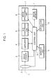
- Fig. 1 is a block diagram depicting an image pickup apparatus according to Embodiment 1 of the present invention.
- the image pickup apparatus is constituted by a digital camera, comprising a lens unit 2, an image sensor 3 (an example of an imaging element), an amplifier 4, an A/D conversion unit 5, an image processing unit 6, an image memory 7, a control unit 8, a monitor unit 9 and an operation unit 10.
- the lens unit 2 is constituted by an optical lens system which receives an optical image of an object, and guides the image to the image sensor 3.
- a zoom lens, a focus lens, and other fixed lens blocks for example, which are disposed in series along the optical axis L of the optical image of the object, can be used.
- the lens unit 2 includes a diaphragm (not illustrated) for adjusting the transmitted light quantity, and a shutter (not illustrated), and driving of the diaphragm and shutter is controlled by the control unit 8.
- the image sensor 3 has a plurality of pixels which are arranged in a matrix of a predetermined number of rows x a predetermined number of columns, and of which photoelectric conversion characteristic changes at an inflection point, performs photoelectric conversion on the optical image formed by the lens unit 2, generates image data constituted by pixel values of each R (red), G (green) and B (blue) color component having a level according to the light quantity, and outputs the image data to the amplifier 4.
- CMOS image sensor For the image sensor 3, a CMOS image sensor, a threshold VMIS (Voltage Modulation Image Sensor) or a CCD image sensor, for example, may be used.
- an image sensor on which pixels of each color component are arranged in an RGB Bayer array, for example, is used for the image sensor 3.
- the image sensor 3 is an image sensor on which a plurality of types of pixels, for reading pixel data on different color components, are cyclically arrayed in a predetermined pattern.
- an image sensor 3 for picking up a monochrome image may be used instead.
- the array direction of the pixels in each row is the horizontal direction
- the array direction of the pixels in each column is the vertical direction.
- the image sensor 3 sequentially outputs the pixel data read by each pixel in the manner of a raster scan from the pixel in the upper left corner to the pixel in the lower right corner.
- the photoelectric conversion characteristic of each pixel is the linear characteristic on the lower brightness side, and the log characteristic on the higher brightness side, as shown in Fig. 5 .
- the change point between the linear characteristic and log characteristic is an inflection point P1, as shown in Fig. 5 .
- the pixel value of the inflection point P1 is called the "flexure start level S".
- the amplifier 4 includes an AGC (Auto Gain Control) circuit and a CDS (Correlated Double Sampling) circuit, for example, and amplifies the image data that is output from the image sensor 3.
- the A/D conversion unit 5 converts the image data of each R, G and B color amplified by the amplifier 4 into digital image data of each R, G and B color.
- the pixel data received by each pixel of the image sensor 3 is converted into image data having 12-bit gradation values.
- the image processing unit 6 executes the later mentioned image processing.
- the image memory 7 is constituted by a RAM (Random Access Memory), and stores image data processed by the image processing unit 6.
- the control unit 8 is constituted by a ROM for storing various control programs, a RAM for temporarily storing data, a control processing unit (CPU) which reads the control programs from ROM and executes them, for example, and controls operation of the entire image pickup apparatus.
- a control processing unit CPU which reads the control programs from ROM and executes them, for example, and controls operation of the entire image pickup apparatus.
- a color liquid crystal display is installed on the rear face of the housing of the image pickup apparatus, for example, and displays an image picked up by the image sensor 3 or an image stored in the image memory 7, on the monitor.
- the operation unit 10 includes various operation switches, such as a power switch, a release switch, a mode setting switch for setting various imaging modes, and a menu selection switch. If the release switch is pressed, a series of imaging operations are executed. In other words, an object is imaged by the image sensor 3, a predetermined image processing is performed on the image data obtained by this imaging operation, and the image data is recorded in the image memory 7. In stead of storing the image data in the image memory 7, the series of imaging operations may be ended with outputting the image data from the image processing unit 6 as digital signals, or converting the digital signals into analog signals and outputting the image data as such analog signals as NTSC.
- various operation switches such as a power switch, a release switch, a mode setting switch for setting various imaging modes, and a menu selection switch.
- Fig. 2 is a block diagram depicting a detailed configuration of the image processing unit 6 shown in Fig. 1 .
- the image processing unit 6 has a black variation correction unit 61, a defect correction unit 62, a Bayer interpolation unit 63, a characteristic conversion unit 64, a gradation conversion unit 65 and a tone curve correction unit 66.
- the black variation correction unit 61 corrects the variations of the black level of each pixel constituting the image sensor 3.
- the defect correction unit 62 performs interpolation, processing, that is, interpolating pixel data read by a defective pixel which can output only a pixel value not greater than a predetermined standard value, using the pixel values of peripheral pixels.
- interpolation processing, that is, interpolating pixel data read by a defective pixel which can output only a pixel value not greater than a predetermined standard value, using the pixel values of peripheral pixels.
- linear interpolation or spline interpolation can be used for the interpolation processing.
- the Bayer interpolation unit 63 executes Bayer interpolation, which is an interpolation processing for interpolating the omitted pixels in each color component, which are generated because each pixel constituting the image sensor 3 is arranged in a Bayer array. Because of this interpolation, image data on one image is represented by three image datum corresponding to three color components: R, G and B. If the image sensor 3 is a monochrome image sensor, the Bayer interpolation unit 63 is unnecessary.
- the characteristic conversion unit 64 has an inflection point variation correction unit 641, an inflection point interpolation unit 642 and a memory unit 643, and converts the photoelectric conversion characteristic of each pixel data into a predetermined reference photoelectric conversion characteristic. Since three image datum corresponding to the color components R, G and B are output from the Bayer interpolation unit 63, the characteristic conversion unit 64 executes the following processing for each of the three image datum corresponding to each color component.
- the characteristic conversion unit 64 uses the linear characteristic as the reference photoelectric conversion characteristic, and converts the log characteristic into the linear characteristic, so as to unify the photoelectric conversion characteristic.
- the inflection point variation correction unit 641 executes a predetermined characteristic conversion processing on the pixel data read by each pixel, so as to unify the photoelectric conversion characteristic of each pixel data into the linear characteristic.
- the inflection point variation correction unit 641 compares the pixel value d of the pixel data read by each pixel with the value of the flexure start level S which is predetermined for each pixel, whereby it is determined whether the pixel data is the pixel data having the linear characteristic or the pixel data having the log characteristic, and if it is the pixel data having the linear characteristic, the pixel value d is directly output as the pixel value d', and if it is the pixel data having the log characteristic, the characteristic conversion processing is executed on the pixel value d, and the obtained pixel value d' is output.
- the inflection point variation correction unit 641 determines that this pixel data is pixel data having the linear characteristic, and if S ⁇ d, the inflection point variation correction unit 641 determines that this pixel data is pixel data having the log characteristic.
- the inflection point variation correction unit 641 can convert the pixel data having the log characteristic into the pixel data having the linear characteristic using a lookup table T, of which correspondence in the case of converting a pixel value in the log area D2 into a pixel value having the linear characteristic is predetermined.
- the lookup table T is a lookup table commonly used for all pixels.
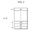
- Fig. 3 is a schematic diagram depicting an example of the data structure of the lookup table T.
- the lookup table T is constituted by n (n is an integer) number of cells to which an address "0" to "n-1 is assigned respectively. Each address corresponds to the relative value of the pixel value d with respect to the flexure start level S, that is, d-S.
- a value d1 to dn is stored in each cell.
- a value generated by converting each pixel value d, belonging to the log area D2 in Fig. 5 into a value on a prolonged line L1 of the linear area D1, is stored in the lookup table T.
- the inflection point variation correction unit 641 outputs a value of the lookup table T stored in the address d-S, that is, a value generated by subtracting the flexure start level S from the pixel value d of this pixel data, so as to convert the log characteristic into the linear characteristic.
- Each address of the lookup table T corresponds to d-S because the variation of the flexure start level S of each pixel is considered.
- the photoelectric conversion characteristic of the log area D2 of each pixel is based on the assumption that the flexure start level S varies but the waveform is approximately the same. Therefore the lookup table T can be applied to all the pixels if each address of the lookup table T corresponds not to d but to d-S.
- the pixel data constituting one image data is input in the predetermined sequence, therefore the pixel which read the input pixel data can be specified based on this sequence, whereby the flexure start level S, which is predetermined for each pixel, can be specified.
- the inflection point interpolation unit 642 outputs the pixel value d" obtained by interpolating the pixel data read by the neighbor pixels located near the target pixel, instead of the pixel value d' obtained by the above mentioned characteristic conversion processing, so as to convert the photoelectric conversion characteristic of the pixel data read by the target pixel into the linear characteristic.
- the inflection point interpolation unit 642 directly outputs the pixel value d', on which characteristic conversion processing was executed by the inflection point variation correction unit 641, as the pixel value d".
- the processing by the inflection point interpolation unit 642 is expressed by the following algorithm, where d(x, y) is a pixel value of the pixel data read by the target pixel, d'(x, y) is a pixel value of the pixel data on which characteristic conversion processing was executed by the inflection point variation correction unit 641, Sth is an inflection point threshold of the target pixel, and Dth is a pixel threshold of the target pixel.
- the inflection point interpolation unit 642 may specify two pixels adjacent to the target pixel in the horizontal direction as neighbor pixels, and output an average value of the two neighbor pixels as d".
- the processing of the inflection point interpolation unit 642 is expressed by the following algorithm.
- the inflection point interpolation unit 642 is a pixel where a filter having a same color as the target pixel is installed, and four pixels located near the target pixel are specified as the neighbor pixels, and an average value of these four pixels is output as d".
- the target pixel is an R pixel
- four pixels - two R pixels located near this R pixel in the horizontal direction and two R pixels located near this R pixel in the vertical direction - are specified as the neighbor pixels.
- the target pixel is a B pixel
- the neighbor pixels are specified in the same manner as the case of the R pixel.
- the target pixel is a G pixel
- four G pixels adjacent to this G pixel in the upper right, lower right, upper left and lower left directions are specified as neighbor pixels.
- Specifying four neighbor pixels is one example, and two pixels, which have a same color filter as the target pixel, and are adjacent to the target pixel in the horizontal direction, may be specified as neighbor pixels.
- the memory unit 643 is constituted by a non-volatile recording media, such as EEPROM, and stores a flexure start level S, which is predetermined for each pixel.
- the memory unit 643 stores the inflection point threshold Sth, the pixel threshold Dth and the lookup table T.
- the inflection start level S is a value unique to each pixel
- the inflection point threshold Sth and the pixel threshold Dth are values common to all the pixels.
- Fig. 4 is a graph depicting a photoelectric conversion characteristic of a pixel in which the pixel value of the inflection point P1 exceeds the inflection point threshold Sth, that is, a pixel in which the pixel value of the inflection point P1 is extremely high, and the ordinate indicates a pixel value, and the abscissa indicates brightness.
- a large saturated area SD is generated on the high brightness side of a pixel, if the pixel value of the inflection point P1 is extremely high.
- the inflection point interpolation unit 642 performs the above mentioned interpolation processing, and not the characteristic conversion processing. Thereby the dynamic range of a pixel in which the pixel value of the inflection point P1 is extremely high can be expanded from DL1 to DL.
- the pixel value d of the pixel data read by a pixel, in which the pixel value of the inflection point P1 is extremely high, is the pixel threshold Dth or less, on the other hand, this pixel data has been converted to have a linear characteristic not by interpolation processing, but by characteristic conversion processing. Thereby a drop in resolution is prevented.
- a saturation level which is the maximum pixel value to specify the dynamic range DL, may be used as the pixel threshold Dth, but using a value slightly lower than the saturation level is preferable, since image reproducibility of the pixel data near the saturation level is not high.
- an average value of the flexure start level S of all the pixels constituting the image sensor 3 may be used, or a value at which the flexure start level S of a high % (e.g. 10%) pixels of the distribution of the flexure start level S of all the pixels exceeds the inflection point threshold Sth may be used.
- the gradation conversion unit 65 performs histogram equalization processing, and dynamic range compression processing among others on the pixel data which is output from the characteristic conversion unit 64.
- the histogram equalization processing is a processing for uniformly distributing the gray levels in an image. By this processing, contrast of an image becomes clearer.
- a technology disclosed in Masami Ogata, "Dynamic Range Compression Technology of an Image,” Image Laboratory (Japan Industrial Publishing Co. Ltd.) (June 2004 ), for example, can be used.
- the tone curve correction unit 66 performs gamma correction on the image data which is output from the gradation conversion unit 65.
- the image data which is output from the tone curve correction unit 66 is stored in the image memory 7 shown in Fig. 1 .
- the operation unit 10 receives an imaging instruction from the user, the image data picked up by the image sensor 3 is amplified to a predetermined level by the amplifier 4, is A/D-converted by the A/D conversion unit 5, and is then input to the image processing unit 6.
- the black level is corrected by the black variation correction unit 61, defective pixels are interpolated by the defect correction unit 62, Bayer interpolation is performed by the Bayer interpolation unit 63, and then resultant pixel data is input to the inflection point variation correction unit 641.
- the photoelectric conversion characteristic is converted into the linear characteristic, and the resultant pixel data is input to the inflection point interpolation unit 642.
- the inflection point interpolation unit 642 executes the above mentioned interpolation processing using the pixel value d' of the neighbor pixels, which is output from the inflection point variation correction unit 641, calculates the pixel value d", and outputs the pixel value d" to the gradation conversion unit 65.
- the inflection point interpolation unit 642 directly outputs the pixel value d' of the target pixel, which is output from the inflection point variation correction unit 641 to the gradation conversion unit 65 as the pixel value d".
- the characteristic of the pixel data read by the target pixel is converted into the linear characteristic by the interpolation processing using the pixel data read by the neighbor pixels.
- the dynamic range of the target pixel can be expanded.
- the pixel data is converted into the pixel data having a linear characteristic, not by the interpolation processing but by the characteristic conversion processing if the pixel value is small.
- the photoelectric conversion characteristic may be converted by the regular characteristic conversion processing if the pixel value is lower than the saturation level.
- Embodiment 2 of the present invention An image pickup apparatus according to Embodiment 2 of the present invention will now be described.
- the image pickup apparatus of the present embodiment is characterized in that the interpolation processing is performed using pixels suitable for the interpolation processing, out of the neighbor pixels in Embodiment 1.
- the inflection point interpolation unit 642 shown in Fig. 2 does not use the pixel data read by a neighbor pixel in which the pixel value is greater than a pixel threshold Dth, and the flexure start level S is greater than the inflection point threshold Sth, for the interpolation processing.
- the inflection point interpolation unit 642 performs the following processing.
- the following processing shows an algorithm in the case when two pixels adjacent to the target pixel in the horizontal direction are the neighbor pixels.
- the second line of the algorithm shows that the flexure start level S of the neighbor pixel on the left side is the inflection point threshold Sth or less, and at the same time, the pixel value d is the pixel threshold Dth or less.
- the third line of the algorithm shows that the flexure start level S of the neighbor pixel on the right side is the inflection point threshold Sth or less, and at the same time, the pixel value d is the pixel threshold Dth or less.
- the fourth line of the algorithm shows that if all the conditions in the first to third lines of the algorithm are satisfied, interpolation processing is performed using the pixel data of the neighbor pixel on the right side, and the neighbor pixel on the left side on which the characteristic conversion processing was performed by the inflection point variation correction unit 641.
- the sixth line of the algorithm shows that if the flexure start level S is the inflection point threshold Sth or less, and if, at the same time, the pixel value d is the pixel threshold Dth or less only in the neighbor pixel on the left side, the interpolation processing is performed using only the pixel data of the neighbor pixel on the left side on which the characteristic conversion processing was performed by the inflection point variation correction unit 641.
- the eighth line of the algorithm shows that if the flexure start level S is the inflection point threshold Sth or less, and if, at the same time, the pixel value d is the pixel threshold Dth or less only in the neighbor pixel on the right side, the interpolation processing is performed using only the pixel data of the neighbor pixel on the right side on which the characteristic conversion processing was performed by the inflection point variation correction unit 641.
- the twelfth line of the algorithm shows that if the condition in the first line of the algorithm is not satisfied, in other words, if the flexure start level S of the target pixel is the inflection point threshold Sth or less, or if the pixel value d of the target pixel is the pixel threshold Dth or less, the pixel data of the target pixel on which the characteristic conversion processing was performed by the inflection point variation correction unit 641 is directly output.
- two pixels adjacent to the target pixel in the horizontal direction are specified as the neighbor pixels, but the present invention is not limited to this, and may be applied to the case of specifying two pixels adjacent to the target pixel in the horizontal direction, and two pixels adjacent to the target pixel in the vertical direction, a total of four pixels, as the neighbor pixels.
- the inflection point interpolation unit 642 performs the interpolation processing using pixel data, other than the pixel data read by pixels, out of the four neighbor pixels, in which the flexure start level S is greater than the inflection point threshold Sth, and at the same time, the pixel value d is greater than the pixel threshold Dth.
- the flexure start level S of the neighbor pixel on the left side is greater than the inflection point threshold Sth, and if, at the same time, the pixel value d is greater than the pixel threshold Dth, it may be determined whether the flexure start level S of the pixel on the left side is the inflection point threshold Sth or less, and at the same time, the pixel value d is the pixel threshold Dth or less, so that the interpolation processing is performed using this pixel as the neighbor pixel if this condition is satisfied.
- a pixel with which the flexure start level S becomes the inflection point threshold Sth or less, and, at the same time, the pixel value d becomes the pixel threshold Dth or less may be sequentially searched toward the left, so that if a pixel which satisfies this condition exists in a search in a predetermined number of pixels, this pixel is used as the neighbor pixel.
- the neighbor pixel can be searched in a same manner as the pixel on the left.
- the target pixel is a pixel in which the pixel value of the inflection point P1 is extremely low, and if the interpolation processing is performed on the pixel data read by this target pixel, the neighbor pixel of which the inflection point is extremely low is not used for interpolation, therefore the interpolation processing can be performed accurately.
- the characteristic conversion unit 64 converts the log characteristic into the linear characteristic, but the present invention is not limited to this, and the linear characteristic may be converted into the log characteristic.
- the characteristic conversion unit 64 converts the log characteristic into the linear characteristic, but the present invention is not limited to this, and can also be applied to the case of converting the log characteristic, the transit characteristic of the linear characteristic and the log characteristic into the linear characteristic.
- the inflection point between the linear characteristic and the transit characteristic may be used as the inflection point P1
- the inflection point between the transit characteristic and the log characteristic may be used as the inflection point P1.
- the characteristic conversion unit 64 may convert the linear characteristic and the transit characteristic into the log characteristic.
- the image pickup apparatus comprises: an imaging element having a plurality of pixels of which photoelectric conversion characteristic changes at an inflection point; and a characteristic conversion unit which converts a photoelectric conversion characteristic of each pixel data into a predetermined reference photoelectric conversion characteristic by executing a predetermined characteristic conversion processing on pixel data read by each pixel, the image pickup apparatus being characterized in that when a pixel value of an inflection point of a target pixel, which is one of the plurality of pixels, is greater than a predetermined inflection point threshold, and when, at the same time, the pixel value of the pixel data read by the target pixel is greater than a predetermined pixel threshold, then the characteristic conversion unit performs interpolation processing using pixel data read by neighbor pixels located near the target pixel, in place of performing the characteristic conversion processing, so as to convert the photoelectric conversion characteristic of the pixel data read by the target pixel into the reference photoelectric conversion characteristic, and when the pixel value of the inflection point of the target pixel is
- the photoelectric conversion characteristic of the pixel data read by the target pixel is converted into the reference photoelectric conversion characteristic by the interpolation processing using the pixel data read by the neighbor pixel.
- the dynamic range of the target pixel can be expanded.
- the photoelectric conversion characteristic can be converted by regular characteristic conversion processing without problem, if the pixel value is lower than the saturation level.
- the photoelectric characteristic of the pixel data is converted into the reference photoelectric conversion characteristic, not by the interpolation processing, but by the characteristic conversion processing, if the pixel value is smaller than the pixel threshold.
- the photoelectric conversion characteristic can be converted into the reference photoelectric conversion characteristic without problem, regardless the pixel value.
- the photoelectric conversion characteristic of the pixel data read by a pixel in which the pixel value of the inflexion point is the inflection point or less, is converted into the reference photoelectric conversion characteristic by the characteristic conversion processing.
- the characteristic conversion unit converts the pixel data read by the neighbor pixel into the reference photoelectric conversion characteristic using the characteristic conversion processing, and executes the interpolation processing on the pixel data read by the target pixel, by using the pixel data of the neighbor pixel after the conversion.
- interpolation processing is performed using the pixel data after the photoelectric conversion characteristic is converted into the reference photoelectric conversion characteristic.
- the characteristic conversion unit does not use, among the neighbor pixels, the pixel data read by a pixel, of which pixel value is greater than the pixel threshold and in which the inflection point is greater than the inflection point threshold, for the interpolation processing.
- the target pixel is a pixel of which the inflection point is extremely high and the dynamic range is narrow, and if interpolation processing is performed on the pixel data read by the target pixel, the neighbor pixels having a photoelectric conversion characteristic similar to that of the target pixel are not used for the interpolation processing, hence the interpolation processing can be performed accurately.
- the characteristic conversion unit specifies the two pixels adjacent to the target pixel in a horizontal direction as the neighbor pixels.
- the characteristic conversion unit specifies two pixels adjacent to the target pixel in a horizontal direction, and two pixels adjacent to the target pixel in a vertical direction as the neighbor pixels.
- the interpolation processing is performed using four neighbor pixels, hence the interpolation processing can be executed accurately.
- a plurality of pixels for reading pixel data having different color components are cyclically arranged with a predetermined pattern in the imaging element, and the characteristic conversion unit specifies pixels which are the same type as the target pixel, and are located near target pixels, as the neighbor pixels.
- the interpolation processing can be executed using pixels, which read the pixel data having the same color as the target pixel, as the neighbor pixels.
Landscapes
- Engineering & Computer Science (AREA)
- Multimedia (AREA)
- Signal Processing (AREA)
- Physics & Mathematics (AREA)
- Nonlinear Science (AREA)
- Transforming Light Signals Into Electric Signals (AREA)
- Color Television Image Signal Generators (AREA)
- Studio Devices (AREA)
Abstract
Description
- The present invention relates to an image pickup apparatus comprising an imaging element constituted by a plurality in pixels of which photoelectric conversion characteristic changes at an inflection point.
- Recently an imaging element constituted by a plurality of pixels of which photoelectric conversion characteristic changes at an inflection point, which is used for expanding the dynamic range, is known. Some of these types of imaging elements have a linear photoelectric conversion characteristic (hereafter called "linear characteristic") on the lower brightness side of the inflection point, and a logarithmic photoelectric conversion characteristic (hereafter called "log characteristic") on the higher brightness side of the inflection point. The photoelectric conversion characteristic that consists of the linear characteristic and the log characteristic is called a "linear log characteristic".
-
Fig. 5 is a graph depicting the linear log characteristic, where the ordinate indicates a pixel value, and the abscissa indicates brightness in a logarithm format. InFig. 5 , a photoelectric conversion characteristic of a pixel PX1 is indicated by the graph G1, and a photoelectric conversion characteristic of another pixel PX2 is indicated by the graph G2. - In the graph G1 in
Fig. 5 , D1 indicates a linear area having a linear characteristic, and D2 indicates a log area having a log characteristic. Then an image processing circuit disposed on the output side of the imaging element performs processing on the pixel data read by the pixels having the linear log characteristic, as preprocessing to perform various image processings, so that the photoelectric conversion characteristic is unified into a linear characteristic or log characteristic. - In the case of unifying the photoelectric conversion characteristic into the linear characteristic, for example, various image processings are performed on the pixel data belonging to the
linear area D 1 shown inFig. 5 , without changing the values thereof, and various image processings are performed on the pixel data belonging to the log area D2, using values converted into the linear characteristic. - In the linear log characteristic, the inflection point P1, which is a start level of the log area D2, normally varies depending on the pixel.
- In the case of determining a dynamic range of an imaging element, as shown in
Fig. 5 , if the dynamic range DL1 is set based on the pixel PX2, in which the pixel value of the inflection point P1 is low, then many saturated areas SD would be generated on the higher brightness side in the photoelectric conversion characteristic of the pixel PX1 in which the pixel value of the inflection point P1 is high. Therefore the dynamic range of the imaging element is determined based on a pixel in which the pixel value of the inflection point P1 is high. - However in the case of determining a dynamic range based on a pixel in which the pixel value of the inflection point P1 is high, the dynamic range of the entire imaging element drops if variance of the inflection point P1 is high, which is a problem.
- For example as
Fig. 5 shows, the range of the dynamic range DL2, which is set based on the pixel PX1 in which the pixel value of the inflection point P1 is high, is much narrower than the range of the dynamic range DL1, which is set based on the pixel PX2 in which the pixel value of the inflection point is low. - Therefore in order to expand the dynamic range, the dynamic range is conventionally set based on the pixel PXn in which the pixel value of the inflection point P1 is relatively high, and a pixel in which the pixel value of the inflection point P1 is higher than that in the pixel PXn is handled as a defective pixel.
Patent Document 1, for example, is available as a document disclosing a prior art related to the present application. - In the prior art however, a pixel, in which a pixel value of the inflection point is high, is regarded as a defective pixel, for which interpolation processing is performed using adjacent pixels in all cases, without considering the specifics of the pixel value. This drops resolution of the images picked up by the imaging element, which is a problem. Furthermore, if a pixel, in which the pixel value of the inflection point P1 is low, is used as the pixel PXn in order to expand the dynamic range, a number of defective pixels increases and a number of pixels to be interpolated increases, which further decreases resolution.
-
- Patent Document 1: Japanese Patent Application Laid-Open No.
2007-251898 - It is an object of the present invention to provide an image pickup apparatus which can suppress a drop in resolution and still expand dynamic range.
- An aspect of the present invention is an image pickup apparatus having: an imaging element having a plurality of pixels of which photoelectric conversion characteristic changes at an inflection point; and a characteristic conversion unit which converts a photoelectric conversion characteristic of each pixel data into a predetermined reference photoelectric conversion characteristic by executing a predetermined characteristic conversion processing on pixel data read by each pixel, the image pickup apparatus being characterized in that when a pixel value of an inflection point of a target pixel, which is one of the plurality of pixels, is greater than a predetermined inflection point threshold, and when, at the same time, the pixel value of the pixel data read by the target pixel is greater than a predetermined pixel threshold, then the characteristic conversion unit performs interpolation processing using pixel data read by neighbor pixels located near the target pixel, in place of performing the characteristic conversion processing, so as to convert the photoelectric conversion characteristic of the pixel data read by the target pixel into the reference photoelectric conversion characteristic, and when the pixel value of the inflection point of the target pixel is the inflection point threshold or less, or when the pixel value of the pixel data read by the target pixel is the pixel threshold or less, then the characteristic conversion unit outputs without modification the pixel value of the target pixel on which the characteristic conversion processing has been executed, so as to convert the photoelectric conversion characteristic of the pixel data read by the target pixel into the reference photoelectric conversion characteristic.
-
- [
Fig. 1] Fig. 1 is a block diagram depicting an image pickup apparatus according toEmbodiment 1 of the present invention. - [
Fig. 2] Fig. 2 is a block diagram depicting a detailed configuration of the image processing unit shown inFig. 1 . - [
Fig. 3] Fig. 3 is a schematic diagram depicting an example of a data structure of a lookup table. - [
Fig. 4] Fig. 4 is a graph depicting a photoelectric conversion characteristic of a pixel in which the pixel value of the inflection point exceeds the inflection point threshold. - [
Fig. 5] Fig. 5 is a graph depicting a linear log characteristic. -
Fig. 1 is a block diagram depicting an image pickup apparatus according toEmbodiment 1 of the present invention. AsFig. 1 shows, the image pickup apparatus is constituted by a digital camera, comprising alens unit 2, an image sensor 3 (an example of an imaging element), anamplifier 4, an A/D conversion unit 5, animage processing unit 6, animage memory 7, acontrol unit 8, amonitor unit 9 and anoperation unit 10. - The
lens unit 2 is constituted by an optical lens system which receives an optical image of an object, and guides the image to theimage sensor 3. For the optical lens system, a zoom lens, a focus lens, and other fixed lens blocks, for example, which are disposed in series along the optical axis L of the optical image of the object, can be used. Thelens unit 2 includes a diaphragm (not illustrated) for adjusting the transmitted light quantity, and a shutter (not illustrated), and driving of the diaphragm and shutter is controlled by thecontrol unit 8. - The
image sensor 3 has a plurality of pixels which are arranged in a matrix of a predetermined number of rows x a predetermined number of columns, and of which photoelectric conversion characteristic changes at an inflection point, performs photoelectric conversion on the optical image formed by thelens unit 2, generates image data constituted by pixel values of each R (red), G (green) and B (blue) color component having a level according to the light quantity, and outputs the image data to theamplifier 4. - For the
image sensor 3, a CMOS image sensor, a threshold VMIS (Voltage Modulation Image Sensor) or a CCD image sensor, for example, may be used. In the present embodiment, an image sensor on which pixels of each color component are arranged in an RGB Bayer array, for example, is used for theimage sensor 3. In other words, theimage sensor 3 is an image sensor on which a plurality of types of pixels, for reading pixel data on different color components, are cyclically arrayed in a predetermined pattern. - This is only an example, and an
image sensor 3 for picking up a monochrome image may be used instead. In the present embodiment, it is assumed that the array direction of the pixels in each row is the horizontal direction, and the array direction of the pixels in each column is the vertical direction. Theimage sensor 3 sequentially outputs the pixel data read by each pixel in the manner of a raster scan from the pixel in the upper left corner to the pixel in the lower right corner. - According to the present embodiment, the photoelectric conversion characteristic of each pixel is the linear characteristic on the lower brightness side, and the log characteristic on the higher brightness side, as shown in
Fig. 5 . The change point between the linear characteristic and log characteristic is an inflection point P1, as shown inFig. 5 . The pixel value of the inflection point P1 is called the "flexure start level S". - The
amplifier 4 includes an AGC (Auto Gain Control) circuit and a CDS (Correlated Double Sampling) circuit, for example, and amplifies the image data that is output from theimage sensor 3. The A/D conversion unit 5 converts the image data of each R, G and B color amplified by theamplifier 4 into digital image data of each R, G and B color. According to the present embodiment, the pixel data received by each pixel of theimage sensor 3 is converted into image data having 12-bit gradation values. - The
image processing unit 6 executes the later mentioned image processing. Theimage memory 7 is constituted by a RAM (Random Access Memory), and stores image data processed by theimage processing unit 6. - The
control unit 8 is constituted by a ROM for storing various control programs, a RAM for temporarily storing data, a control processing unit (CPU) which reads the control programs from ROM and executes them, for example, and controls operation of the entire image pickup apparatus. - For the
monitor unit 9, a color liquid crystal display is installed on the rear face of the housing of the image pickup apparatus, for example, and displays an image picked up by theimage sensor 3 or an image stored in theimage memory 7, on the monitor. - The
operation unit 10 includes various operation switches, such as a power switch, a release switch, a mode setting switch for setting various imaging modes, and a menu selection switch. If the release switch is pressed, a series of imaging operations are executed. In other words, an object is imaged by theimage sensor 3, a predetermined image processing is performed on the image data obtained by this imaging operation, and the image data is recorded in theimage memory 7. In stead of storing the image data in theimage memory 7, the series of imaging operations may be ended with outputting the image data from theimage processing unit 6 as digital signals, or converting the digital signals into analog signals and outputting the image data as such analog signals as NTSC. -
Fig. 2 is a block diagram depicting a detailed configuration of theimage processing unit 6 shown inFig. 1 . Theimage processing unit 6 has a blackvariation correction unit 61, adefect correction unit 62, a Bayerinterpolation unit 63, acharacteristic conversion unit 64, agradation conversion unit 65 and a tonecurve correction unit 66. - The black
variation correction unit 61 corrects the variations of the black level of each pixel constituting theimage sensor 3. Thedefect correction unit 62 performs interpolation, processing, that is, interpolating pixel data read by a defective pixel which can output only a pixel value not greater than a predetermined standard value, using the pixel values of peripheral pixels. Here linear interpolation or spline interpolation can be used for the interpolation processing. - The Bayer
interpolation unit 63 executes Bayer interpolation, which is an interpolation processing for interpolating the omitted pixels in each color component, which are generated because each pixel constituting theimage sensor 3 is arranged in a Bayer array. Because of this interpolation, image data on one image is represented by three image datum corresponding to three color components: R, G and B. If theimage sensor 3 is a monochrome image sensor, the Bayerinterpolation unit 63 is unnecessary. - The
characteristic conversion unit 64 has an inflection pointvariation correction unit 641, an inflectionpoint interpolation unit 642 and amemory unit 643, and converts the photoelectric conversion characteristic of each pixel data into a predetermined reference photoelectric conversion characteristic. Since three image datum corresponding to the color components R, G and B are output from theBayer interpolation unit 63, thecharacteristic conversion unit 64 executes the following processing for each of the three image datum corresponding to each color component. - In the present embodiment, the
characteristic conversion unit 64 uses the linear characteristic as the reference photoelectric conversion characteristic, and converts the log characteristic into the linear characteristic, so as to unify the photoelectric conversion characteristic. - The inflection point
variation correction unit 641 executes a predetermined characteristic conversion processing on the pixel data read by each pixel, so as to unify the photoelectric conversion characteristic of each pixel data into the linear characteristic. - The inflection point
variation correction unit 641 compares the pixel value d of the pixel data read by each pixel with the value of the flexure start level S which is predetermined for each pixel, whereby it is determined whether the pixel data is the pixel data having the linear characteristic or the pixel data having the log characteristic, and if it is the pixel data having the linear characteristic, the pixel value d is directly output as the pixel value d', and if it is the pixel data having the log characteristic, the characteristic conversion processing is executed on the pixel value d, and the obtained pixel value d' is output. - In concrete terms, if the pixel value d of the pixel data which is output from the
Bayer interpolation unit 63 is d < S, the inflection pointvariation correction unit 641 determines that this pixel data is pixel data having the linear characteristic, and if S ≤ d, the inflection pointvariation correction unit 641 determines that this pixel data is pixel data having the log characteristic. - Here the inflection point
variation correction unit 641 can convert the pixel data having the log characteristic into the pixel data having the linear characteristic using a lookup table T, of which correspondence in the case of converting a pixel value in the log area D2 into a pixel value having the linear characteristic is predetermined. - In this case, the lookup table T is a lookup table commonly used for all pixels.
Fig. 3 is a schematic diagram depicting an example of the data structure of the lookup table T. - As
Fig. 3 shows, the lookup table T is constituted by n (n is an integer) number of cells to which an address "0" to "n-1 is assigned respectively. Each address corresponds to the relative value of the pixel value d with respect to the flexure start level S, that is, d-S. In each cell, a value d1 to dn, after converting the value, generated by subtracting the flexure start level S from the pixel value d in the log area D2, into a value having the linear characteristic, is stored. - In other words, a value generated by converting each pixel value d, belonging to the log area D2 in
Fig. 5 into a value on a prolonged line L1 of the linear area D1, is stored in the lookup table T. - Therefore if the input pixel data is pixel data having the log characteristic, the inflection point
variation correction unit 641 outputs a value of the lookup table T stored in the address d-S, that is, a value generated by subtracting the flexure start level S from the pixel value d of this pixel data, so as to convert the log characteristic into the linear characteristic. - Each address of the lookup table T corresponds to d-S because the variation of the flexure start level S of each pixel is considered. In other words, in the present embodiment, the photoelectric conversion characteristic of the log area D2 of each pixel is based on the assumption that the flexure start level S varies but the waveform is approximately the same. Therefore the lookup table T can be applied to all the pixels if each address of the lookup table T corresponds not to d but to d-S.
- In the inflection point
variation correction unit 641, the pixel data constituting one image data is input in the predetermined sequence, therefore the pixel which read the input pixel data can be specified based on this sequence, whereby the flexure start level S, which is predetermined for each pixel, can be specified. - Referring back to
Fig. 2 , if the flexure start level S of a target pixel, which is one of a plurality of pixels, is greater than a predetermined inflection point threshold, and if, at the same time, the pixel value d of the pixel data read by the target pixel is greater than a predetermined pixel threshold, then the inflectionpoint interpolation unit 642 outputs the pixel value d" obtained by interpolating the pixel data read by the neighbor pixels located near the target pixel, instead of the pixel value d' obtained by the above mentioned characteristic conversion processing, so as to convert the photoelectric conversion characteristic of the pixel data read by the target pixel into the linear characteristic. - If the flexure start level S of the target pixel is the inflection point threshold or less, or if the pixel value d of the pixel data read by the target pixel is the predetermined threshold or less, then the inflection
point interpolation unit 642 directly outputs the pixel value d', on which characteristic conversion processing was executed by the inflection pointvariation correction unit 641, as the pixel value d". - In concrete terms, the processing by the inflection
point interpolation unit 642 is expressed by the following algorithm, where d(x, y) is a pixel value of the pixel data read by the target pixel, d'(x, y) is a pixel value of the pixel data on which characteristic conversion processing was executed by the inflection pointvariation correction unit 641, Sth is an inflection point threshold of the target pixel, and Dth is a pixel threshold of the target pixel. -
 if (S > Sth&d(x,y) > Dth)
 d"(x,y) = ((d'(x-1,y)+d'(x+1,y)+d'(x,y-1)+d'(x,y+ 1))/4
 else
 d"(x,y) = d'(x,y)
In the above example, the inflection
if (S > Sth&d(x,y) > Dth) d"(x,y) = ((d'(x-1,y)+d'(Inx+ 1,y))/2 else d"(x,y) = d'(x,y)
 if (S > Sth&d(x,y) > Dth)
 drb"(x,y) = ((drb'(x-2,y)+drb'(x+2,y)+drb'(x,y-2)+drb'(x,y+2))/4
 dg"(x,y) = ((dg'(x-1,y-1)+dg'(x+1,y-1)+dg'(x-1,y+1)+dg(x+1,y+1))/4
 else
 drb"(x,y) = drb'(x,y)
 dg"(x,y) = dg'(x,y)
Where drb is a pixel value of the pixel data read by the pixel, a red or blue filter is installed (R pixel or B pixel) in the Bayer array, and dg is a pixel value of the pixel data read by the pixel where a green filter is installed (G pixel).
- 1: if (S(x,y) > Sth&d(x,y) > Dth){
- 2: if (S(x-1,y) ≤ Sth&d(x-1,y) ≤ Dth{
- 3: if (S(x+1,y) ≤ Sth&d(x+1,y) ≤ Dth
- 4: d"(x,y) = (d'(x-1,y)+d'(x+1,y))/2
- 5: else
- 6: d"(x,y) = d'(x-1,y)
- 7: }else{
- 8: if (S(x+1,y) ≤ Sth&d(x+1,y) ≤ Dth)
- 9: d"(x,y) = ((d'(x+1,y)
- 10: }
- 11:}else
- 12: d"(x,y) = d'(x,y)
Claims (6)
- An image pickup apparatus comprising:an imaging element having a plurality of pixels of which photoelectric conversion characteristic changes at an inflection point; anda characteristic conversion unit which converts a photoelectric conversion characteristic of each pixel data into a predetermined reference photoelectric conversion characteristic by executing a predetermined characteristic conversion processing on pixel data read by each pixel, whereinwhen a pixel value of an inflection point of a target pixel, which is one of the plurality of pixels, is greater than a predetermined inflection point threshold, and when, at the same time, the pixel value of the pixel data read by the target pixel is greater than a predetermined pixel threshold, then the characteristic conversion unit performs interpolation processing using pixel data read by neighbor pixels located near the target pixel, in place of performing the characteristic conversion processing, so as to convert the photoelectric conversion characteristic of the pixel data read by the target pixel into the reference photoelectric conversion characteristic, andwhen the pixel value of the inflection point of the target pixel is the inflection point threshold or less, or when the pixel value of the pixel data read by the target pixel is the pixel threshold or less, then the characteristic conversion unit outputs without modification the pixel value of the target pixel on which the characteristic conversion processing has been executed, so as to convert the photoelectric conversion characteristic of the pixel data read by the target pixel into the reference photoelectric conversion characteristic.
- The image pickup apparatus according to Claim 1, wherein the characteristic conversion unit converts the pixel data read by the neighbor pixel into the reference photoelectric conversion characteristic using the characteristic conversion processing, and executes the interpolation processing on the pixel data read by the target pixel, by using the pixel data of the neighbor pixel after the conversion.
- The image pickup apparatus according to Claim 1 or 2, wherein the characteristic conversion unit does not use, among the neighbor pixels, the pixel data read by a pixel, of which pixel value is greater than the pixel threshold and in which the inflection point is greater than the inflection point threshold, for the interpolation processing.
- The image pickup apparatus according to any of Claims 1 to 3, wherein the characteristic conversion unit specifies the two pixels adjacent to the target pixel in a horizontal direction as the neighbor pixels.
- The image pickup apparatus according to any of Claims 1 to 3, wherein the characteristic conversion unit specifies two pixels adjacent to the target pixel in a horizontal direction and two pixels adjacent to the target pixel in a vertical direction as the neighbor pixels.
- The image pickup apparatus according to any of Claims 1 to 5, wherein a plurality of types of pixels for reading pixel data having different color components are cyclically arranged with a predetermined pattern in the imaging element, and the characteristic conversion unit specifies pixels which are the same type as the target pixel and are located near target pixels, as the neighbor pixels.
Applications Claiming Priority (2)
| Application Number | Priority Date | Filing Date | Title |
|---|---|---|---|
| JP2009142091 | 2009-06-15 | ||
| PCT/JP2010/001851 WO2010146748A1 (en) | 2009-06-15 | 2010-03-16 | Image pickup apparatus |
Publications (2)
| Publication Number | Publication Date |
|---|---|
| EP2445198A1 true EP2445198A1 (en) | 2012-04-25 |
| EP2445198A4 EP2445198A4 (en) | 2014-05-14 |
Family
ID=43356085
Family Applications (1)
| Application Number | Title | Priority Date | Filing Date |
|---|---|---|---|
| EP10789133.5A Withdrawn EP2445198A4 (en) | 2009-06-15 | 2010-03-16 | Image pickup apparatus |
Country Status (4)
| Country | Link |
|---|---|
| US (1) | US20120092539A1 (en) |
| EP (1) | EP2445198A4 (en) |
| JP (2) | JP4586942B1 (en) |
| WO (1) | WO2010146748A1 (en) |
Families Citing this family (6)
| Publication number | Priority date | Publication date | Assignee | Title |
|---|---|---|---|---|
| EP2445199A4 (en) * | 2009-06-15 | 2014-04-30 | Konica Minolta Opto Inc | IMAGE CAPTURE APPARATUS |
| US20120092539A1 (en) * | 2009-06-15 | 2012-04-19 | Tetsuya Katagiri | Image Pickup Apparatus |
| CN103404123B (en) | 2011-02-28 | 2017-10-20 | 富士胶片株式会社 | Imaging device and defect pixel correction method |
| WO2012150660A1 (en) * | 2011-05-02 | 2012-11-08 | コニカミノルタアドバンストレイヤー株式会社 | Image capture device |
| US9892487B1 (en) * | 2016-11-28 | 2018-02-13 | Sony Corporation | Method and apparatus for combining pixel values in array including linear pixels and logarithmic pixels |
| CN116844495A (en) * | 2023-07-26 | 2023-10-03 | 重庆惠科金渝光电科技有限公司 | Pixel gray scale compensation method, device, computer media and display equipment |
Family Cites Families (14)
| Publication number | Priority date | Publication date | Assignee | Title |
|---|---|---|---|---|
| JPH11298799A (en) * | 1998-04-15 | 1999-10-29 | Honda Motor Co Ltd | Optical sensor signal processing device |
| JP2000209506A (en) * | 1999-01-14 | 2000-07-28 | Toshiba Corp | Imaging device and imaging method |
| JP3493405B2 (en) * | 2000-08-31 | 2004-02-03 | ミノルタ株式会社 | Solid-state imaging device |
| JP4383827B2 (en) * | 2003-10-31 | 2009-12-16 | キヤノン株式会社 | Imaging apparatus, white defect correction method, computer program, and computer-readable recording medium |
| JP4556722B2 (en) * | 2004-05-31 | 2010-10-06 | コニカミノルタホールディングス株式会社 | Imaging device |
| JP4617870B2 (en) * | 2004-12-22 | 2011-01-26 | ソニー株式会社 | Imaging apparatus and method, and program |
| JP4792943B2 (en) * | 2005-11-30 | 2011-10-12 | コニカミノルタホールディングス株式会社 | Imaging device |
| JP4710617B2 (en) * | 2006-01-12 | 2011-06-29 | コニカミノルタホールディングス株式会社 | Imaging apparatus and imaging method |
| JP2007228152A (en) * | 2006-02-22 | 2007-09-06 | Fujifilm Corp | Solid-state imaging device and imaging method |
| JP4893042B2 (en) * | 2006-03-20 | 2012-03-07 | コニカミノルタホールディングス株式会社 | Imaging device |
| EP2028846A4 (en) * | 2006-06-14 | 2011-11-02 | Konica Minolta Holdings Inc | IMAGE FORMING DEVICE |
| JP2008028623A (en) * | 2006-07-20 | 2008-02-07 | Konica Minolta Holdings Inc | Imaging apparatus |
| JP5013812B2 (en) * | 2006-10-26 | 2012-08-29 | キヤノン株式会社 | Imaging apparatus and correction method |
| US20120092539A1 (en) * | 2009-06-15 | 2012-04-19 | Tetsuya Katagiri | Image Pickup Apparatus |
-
2010
- 2010-03-16 US US13/378,669 patent/US20120092539A1/en not_active Abandoned
- 2010-03-16 WO PCT/JP2010/001851 patent/WO2010146748A1/en not_active Ceased
- 2010-03-16 JP JP2010524278A patent/JP4586942B1/en not_active Expired - Fee Related
- 2010-03-16 EP EP10789133.5A patent/EP2445198A4/en not_active Withdrawn
- 2010-09-08 JP JP2010200539A patent/JP2011024246A/en active Pending
Also Published As
| Publication number | Publication date |
|---|---|
| JP4586942B1 (en) | 2010-11-24 |
| US20120092539A1 (en) | 2012-04-19 |
| EP2445198A4 (en) | 2014-05-14 |
| JP2011024246A (en) | 2011-02-03 |
| WO2010146748A1 (en) | 2010-12-23 |
| JPWO2010146748A1 (en) | 2012-11-29 |
Similar Documents
| Publication | Publication Date | Title |
|---|---|---|
| US7916191B2 (en) | Image processing apparatus, method, program, and recording medium | |
| US6201530B1 (en) | Method and system of optimizing a digital imaging processing chain | |
| JP5014099B2 (en) | Imaging apparatus and control method thereof | |
| US20110102649A1 (en) | Pixel defect detection and correction device, imaging apparatus, pixel defect detection and correction method, and program | |
| US6181830B1 (en) | Image signal correction device | |
| EP2445198A1 (en) | Image pickup apparatus | |
| US20100079622A1 (en) | Imaging device, setting-value changing method, and computer program product | |
| CN101505368A (en) | Progressive-to-interlace conversion method, image processing apparatus, and imaging apparatus | |
| US20060232692A1 (en) | Image pickup apparatus | |
| US7710470B2 (en) | Image processing apparatus that reduces noise, image processing method that reduces noise, electronic camera that reduces noise, and scanner that reduces noise | |
| US8068149B2 (en) | Image processing device, image processing method, and image pickup apparatus | |
| JP5977565B2 (en) | Image processing device | |
| US20120092537A1 (en) | Image Pickup Apparatus | |
| JP2004320128A (en) | Defective pixel correction device | |
| JP4470901B2 (en) | Imaging apparatus, high-frequency component detection circuit, high-frequency component detection method, and computer program | |
| US8576307B2 (en) | Imaging device having a characteristic converting section | |
| JP2006041687A (en) | Image processing apparatus, image processing method, image processing program, electronic camera, and scanner | |
| JP2000041179A (en) | Shading correction method for image input device and image input device | |
| JP2012080297A (en) | Imaging device, and imaging control method of the same | |
| JP2010093759A (en) | Imaging sensor and imaging apparatus | |
| JP4479429B2 (en) | Imaging device | |
| JP4732795B2 (en) | Solid-state imaging device and image correction method | |
| JP2005086630A (en) | Imaging apparatus | |
| JP4720130B2 (en) | Imaging device | |
| JP2010193112A (en) | Image processing apparatus and digital still camera |
Legal Events
| Date | Code | Title | Description |
|---|---|---|---|
| PUAI | Public reference made under article 153(3) epc to a published international application that has entered the european phase |
Free format text: ORIGINAL CODE: 0009012 |
|
| 17P | Request for examination filed |
Effective date: 20120109 |
|
| AK | Designated contracting states |
Kind code of ref document: A1 Designated state(s): AT BE BG CH CY CZ DE DK EE ES FI FR GB GR HR HU IE IS IT LI LT LU LV MC MK MT NL NO PL PT RO SE SI SK SM TR |
|
| DAX | Request for extension of the european patent (deleted) | ||
| A4 | Supplementary search report drawn up and despatched |
Effective date: 20140416 |
|
| RIC1 | Information provided on ipc code assigned before grant |
Ipc: H04N 5/367 20110101ALI20140410BHEP Ipc: H04N 5/355 20110101ALI20140410BHEP Ipc: H04N 5/335 20110101AFI20140410BHEP Ipc: H04N 5/243 20060101ALI20140410BHEP |
|
| STAA | Information on the status of an ep patent application or granted ep patent |
Free format text: STATUS: THE APPLICATION IS DEEMED TO BE WITHDRAWN |
|
| 18D | Application deemed to be withdrawn |
Effective date: 20141118 |