EP2444651A1 - Valve assembly for an injection valve and injection valve - Google Patents
Valve assembly for an injection valve and injection valve Download PDFInfo
- Publication number
- EP2444651A1 EP2444651A1 EP10188087A EP10188087A EP2444651A1 EP 2444651 A1 EP2444651 A1 EP 2444651A1 EP 10188087 A EP10188087 A EP 10188087A EP 10188087 A EP10188087 A EP 10188087A EP 2444651 A1 EP2444651 A1 EP 2444651A1
- Authority
- EP
- European Patent Office
- Prior art keywords
- valve
- armature part
- armature
- valve needle
- valve assembly
- Prior art date
- Legal status (The legal status is an assumption and is not a legal conclusion. Google has not performed a legal analysis and makes no representation as to the accuracy of the status listed.)
- Granted
Links
Images


Classifications
-
- F—MECHANICAL ENGINEERING; LIGHTING; HEATING; WEAPONS; BLASTING
- F02—COMBUSTION ENGINES; HOT-GAS OR COMBUSTION-PRODUCT ENGINE PLANTS
- F02M—SUPPLYING COMBUSTION ENGINES IN GENERAL WITH COMBUSTIBLE MIXTURES OR CONSTITUENTS THEREOF
- F02M51/00—Fuel-injection apparatus characterised by being operated electrically
- F02M51/06—Injectors peculiar thereto with means directly operating the valve needle
- F02M51/061—Injectors peculiar thereto with means directly operating the valve needle using electromagnetic operating means
- F02M51/0625—Injectors peculiar thereto with means directly operating the valve needle using electromagnetic operating means characterised by arrangement of mobile armatures
- F02M51/0628—Injectors peculiar thereto with means directly operating the valve needle using electromagnetic operating means characterised by arrangement of mobile armatures having a stepped armature
-
- F—MECHANICAL ENGINEERING; LIGHTING; HEATING; WEAPONS; BLASTING
- F02—COMBUSTION ENGINES; HOT-GAS OR COMBUSTION-PRODUCT ENGINE PLANTS
- F02M—SUPPLYING COMBUSTION ENGINES IN GENERAL WITH COMBUSTIBLE MIXTURES OR CONSTITUENTS THEREOF
- F02M51/00—Fuel-injection apparatus characterised by being operated electrically
- F02M51/06—Injectors peculiar thereto with means directly operating the valve needle
- F02M51/061—Injectors peculiar thereto with means directly operating the valve needle using electromagnetic operating means
- F02M51/0625—Injectors peculiar thereto with means directly operating the valve needle using electromagnetic operating means characterised by arrangement of mobile armatures
-
- F—MECHANICAL ENGINEERING; LIGHTING; HEATING; WEAPONS; BLASTING
- F02—COMBUSTION ENGINES; HOT-GAS OR COMBUSTION-PRODUCT ENGINE PLANTS
- F02M—SUPPLYING COMBUSTION ENGINES IN GENERAL WITH COMBUSTIBLE MIXTURES OR CONSTITUENTS THEREOF
- F02M61/00—Fuel-injectors not provided for in groups F02M39/00 - F02M57/00 or F02M67/00
- F02M61/04—Fuel-injectors not provided for in groups F02M39/00 - F02M57/00 or F02M67/00 having valves, e.g. having a plurality of valves in series
- F02M61/10—Other injectors with elongated valve bodies, i.e. of needle-valve type
Landscapes
- Engineering & Computer Science (AREA)
- Chemical & Material Sciences (AREA)
- Combustion & Propulsion (AREA)
- Mechanical Engineering (AREA)
- General Engineering & Computer Science (AREA)
- Physics & Mathematics (AREA)
- Electromagnetism (AREA)
- Fuel-Injection Apparatus (AREA)
- Magnetically Actuated Valves (AREA)
Abstract
a valve body (14) including a central longitudinal axis (L), the valve body (14) comprising a cavity (18) with a fluid inlet portion (42) and a fluid outlet portion (40), the fluid inlet portion (42) being provided with a first step (43),
a valve needle (20) axially movable in the cavity (18), the valve needle (20) preventing a fluid flow through the fluid outlet portion (40) in a closing position and releasing the fluid flow through the fluid outlet portion (40) in an open position, and
an electro-magnetic actuator unit (36) being designed to actuate the valve needle (20), the electro-magnetic actuator unit (36) comprising an armature (21, 22) axially movable in the cavity (18), wherein the armature (21, 22) comprises a first armature part (21) being fixedly coupled to the valve needle (20) and a second armature part (22) being axially movable relative to the first armature part (21), the second armature part (22) being designed in a way that the second armature part (22) is mechanically decoupled from the first armature part (21) by hitting the first step (43) when the valve needle (20) reaches its open position.
Description
- The invention relates to a valve assembly for an injection valve and an injection valve.
- Injection valves are in wide spread use, in particular for internal combustion engines where they may be arranged in order to dose the fluid into an intake manifold of the internal combustion engine or directly into the combustion chamber of a cylinder of the internal combustion engine.
- Injection valves are manufactured in various forms in order to satisfy the various needs for the various combustion engines. Therefore, for example, their length, their diameter and also various elements of the injection valve being responsible for the way the fluid is dosed may vary in a wide range. In addition to that, injection valves may accommodate an actuator for actuating a needle of the injection valve, which may, for example, be an electromagnetic actuator or piezo electric actuator.
- In order to enhance the combustion process in view of the creation of unwanted emissions, the respective injection valve may be suited to dose fluids under very high pressures. The pressures may be in case of a gasoline engine, for example, in the range of up to 200 bar and even higher, and in the case of diesel engines in the range of up to 2000 bar and even higher.
- The object of the invention is to create a valve assembly and an injection valve which facilitate a reliable and precise function. These objects are achieved by the features of the independent claims. Advantageous embodiments of the invention are given in sub-claims.
- The invention is distinguished by a valve assembly for an injection valve, comprising a valve body including a central longitudinal axis, the valve body comprising a cavity with a fluid inlet portion and a fluid outlet portion, the fluid inlet portion being provided with a first step, and a valve needle axially moveable in the cavity, the valve needle preventing a fluid flow through the fluid outlet portion in a closing position and releasing the fluid flow through the fluid outlet portion in an open position. Furthermore, the valve assembly comprises an electro-magnetic actuator unit which is designed to actuate the valve needle. The electro-magnetic actuator unit comprises an armature which is axially movable in the cavity. The armature comprises a first armature part being fixedly coupled to the valve needle and a second armature part being axially movable relative to the first armature part. The second armature part is designed in a way that the second armature part is mechanically decoupled from the first armature part by hitting the first step when the valve needle reaches its open position.
- When, in operation, moving the valve needle from the open position to the closing position, the first armature part is, together with the valve needle, moved from the open position in direction to the fuel outlet position. Thereby it meets the second armature part and hits it. When hitting, the first armature part hands over kinetic energy as a pulse to the second armature part according to Newton's law. Subsequently, the first armature part is accelerated again due to the force of the main spring until the valve needle reaches its closing position. The closing position is reached at a lower speed of the needle compared with a valve assembly, where the armature consists only of one piece having the mass of both of the armature parts of the valve assembly according to the present invention. This has the advantage that the first armature part can guide the valve needle in the valve body in a reliable manner and the second armature part can move in the cavity with a limited dependency from the first armature part. Due to the separation of the second armature part from the first armature part it can be avoided that the mass of the second armature part influences the dynamic behavior of the valve needle during the closing process of the injection valve. As the first armature part can have a small mass, the dynamic forces of the valve needle on the valve body can be kept small. Consequently, wearing effects on the valve body due the valve needle can be kept small. Furthermore, the second armature part can contribute to a maximum electromagnetic force on the valve needle during the opening phase of the valve needle and a secure opening of the valve needle can be obtained in case that the second armature part is of magnetic material.
- If the mass of the first armature part plus the mass of the valve needle is equal to the mass of the second armature part, then all of the kinetic energy of the first armature part plus the mass of the valve needle is handed over to the second armature part, when the first armature part hits the second armature part. Independently of the mass relation between the mass of the second armature part versus the added masses of the valve needle plus the first armature part the danger of bouncing (= unwanted reopening of the needle immediately after reaching the closing position) is avoided or, at least, minimized by splitting the armature into two armature parts.
- As the valve needle reaches its closing position at a lower speed compared with a traditional valve assembly, where the armature consists only of one piece, the so-called seat detection signal is smaller than with a traditional valve assembly. This might create problems in detecting the seat detection signal. However, the invention has the advantage, that instead a signal can be detected, when the first armature part hits the second armature part. This signal is of a good quality, and it can be used analog to said seat detection signal.
- In an advantageous embodiment the second armature part is arranged relative to the first armature part in axial direction towards the fluid outlet portion. By this a simple arrangement of the first armature part and the second armature part is possible.
- In a further advantageous embodiment the second armature part is axially movable between the first armature part and a stop device. This has the advantage that a defined axial movement range of the second armature part can be obtained.
- In a further advantageous embodiment the stop device comprises a second step in the valve body. By this a simple embodiment of the stop device is possible.
- In a further advantageous embodiment the stop device comprises an armature spring fixedly coupled to the valve body. By this a soft, elastic movement of the second armature part and a reliable transmission of the kinetic energy from the second armature part to the stop device are possible.
- In a further advantageous embodiment the armature spring is a coil spring being coupled to the second step in the valve body. This has the advantage that a simple shape of the armature spring and a secure arrangement of the armature spring in the cavity of the valve body can be obtained. Furthermore, a reliable transmission of the kinetic energy from the second armature part to the armature spring and further to the valve body can be obtained.
- In a further advantageous embodiment the stop device comprises a protrusion extending in radial direction from the valve needle and being rigidly coupled to the valve needle. This has the advantage that a limited displacement between the first and the second armature part is possible. Furthermore, the shape of the stop element can be very simple.
- In a further advantageous embodiment the second armature part is of a magnetic material. By this the second armature part can contribute to a maximum electromagnetic force on the valve needle during the opening phase of the valve needle and a secure opening of the valve needle can be obtained.
- However, in another advantageous embodiment the second armature part is of a non-magnetic material. This has the advantage, that in a case, where a second armature part made of magnetic material might have negative influence onto the valve needle, such an influence can be avoided.
- Exemplary embodiments of the invention are explained in the following with the aid of schematic drawings. These are as follows:
-
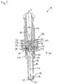
Figure 1 , an injection valve with a first embodiment of a valve assembly in a longitudinal section view, -
Figure 2 , an arrangement of a first and of a second armature part and of a valve needle, all of a valve assembly according to the invention, in an enlarged view, and -
Figures 3a to 3d , the construction ofFig. 2 , shown in different phases of operation. - Elements of the same design and function that appear in different illustrations are identified by the same reference character.
- An
injection valve 10 that is in particular suitable for dosing fuel to an internal combustion engine is shown inFig. 1 . It comprises in particular avalve assembly 11 and aninlet tube 12. - The
valve assembly 11 comprises avalve body 14 with a central longitudinal axis L and ahousing 16. Thehousing 16 is partially arranged around thevalve body 14. Acavity 18 is arranged in thevalve body 14. - The
cavity 18 takes in avalve needle 20, afirst armature part 21 and asecond armature part 22, which will be described in detail later. Thefirst armature part 21 may have anupper guide 23 formed as a collar around thevalve needle 14, as shown inFig. 1 . Amain spring 24 is arranged in arecess 26 provided in theinlet tube 12. Themain spring 24 is mechanically coupled to theupper guide 23 at anaxial end 29 of theupper guide 23. Theupper guide 23 is in one piece with thearmature 21. Theupper guide 23 is in contact with an inner side of theinlet tube 12 and can guide thevalve needle 14 in axial direction inside theinlet tube 12. Alternatively, theupper guide 23 is arranged adjacent to an axial end of thevalve needle 20 and is fixedly coupled to thevalve needle 20. However, it is not necessary to have theupper guide 23. In this case, which is shown inFig. 2 , themain spring 24 is mechanically coupled to thefirst armature part 21, which, in turn, guides thevalve needle 20. - The
axial end 29 of theinlet tube 12 is formed as afirst step 43, against which thesecond armature part 22 hits when thevalve needle 20 is actuated. - A
filter element 30 is arranged in theinlet tube 12 and forms a further seat for themain spring 24. During the manufacturing process of theinjection valve 10 thefilter element 30 can be axially moved in theinlet tube 12 in order to preload themain spring 24 in a desired manner. By this themain spring 24 exerts a force on thevalve needle 20 towards aninjection nozzle 34 of theinjection valve 10. - In a closing position of the
valve needle 20 it sealingly rests on aseat plate 32 by this preventing a fluid flow through the at least oneinjection nozzle 34. Theinjection nozzle 34 may be, for example, an injection hole. However, it may also be of some other type suitable for dosing fluid. In addition to that a lower guide 35 is provided adjacent to theseat plate 32. The lower guide 35 is adapted to guide thevalve needle 20 near theinjection nozzle 34. Theseat plate 32 may be made in one part with the lower guide 35 or a separate part from the lower guide 35. - The
valve assembly 11 is provided with anactuator unit 36 that is preferably an electro-magnetic actuator. The electro-magnetic actuator unit 36 comprises acoil 38, which is preferably arranged inside thehousing 16 and overmolded. Furthermore, the electro-magnetic actuator unit 36 comprises thearmature armature cavity 18. Thearmature first armature part 21 and asecond armature part 22. Thefirst armature part 21 is fixedly coupled to thevalve needle 20. Thesecond armature part 22 is axially movable relative to thefirst armature part 21. Thesecond armature part 22 is arranged relative to thefirst armature part 21 in axial direction towards afluid outlet portion 40 which is a part of thecavity 18 near theseat plate 32. Thefluid outlet portion 40 communicates with afluid inlet portion 42 which is provided in thevalve body 14. - The
housing 16, theinlet tube 12, thefirst armature part 21 and thesecond armature part 22 are forming an electromagnetic circuit together with thevalve body 14, if thesecond armature part 22 is of a magnetic material. However, if thesecond armature part 22 is of a non-magnetic material, only thehousing 16, theinlet tube 12 and thefirst armature part 21 are forming an electromagnetic circuit together with thevalve body 14. - The
valve assembly 11 has astop device second armature part 22 is axially movable between thefirst step 43 and thestop device - In the embodiment of
Figure 1 , the stop device has asecond step 44 which is arranged in thevalve body 14. Anarmature spring 46 which is preferably a coil spring is fixedly coupled to thestep 44 in thevalve body 14. Thearmature spring 46 forms a soft stop element for thesecond armature part 22 which is axially movable between thefirst step 43 and thearmature spring 46. - In the embodiment of
Figure 2 , which shows an arrangement of thefirst armature part 21, thesecond armature part 22 and thevalve needle 20 in more detail, the stop device has aprotrusion 48 which extends in radial direction from thevalve needle 20. Theprotrusion 48 is rigidly coupled to thevalve needle 20. Preferably, theprotrusion 48 is shaped as a ring element. However, theprotrusion 48 instead may comprise at least two pin elements extending in radial direction. Theprotrusion 48 forms a rigid stop element for thesecond armature part 22 which is axially movable between thefirst step 43 and theprotrusion 48. - In the following, the function of the
injection valve 10 is described in detail, thereby referring to theFig. 3a to 3d : The fluid is led from thefluid inlet portion 42 towards thefluid outlet portion 40. - The
valve needle 20 prevents a fluid flow through thefluid outlet portion 40 in thevalve body 14 in a closing position of thevalve needle 20. Outside of the closing position of thevalve needle 20, thevalve needle 20 enables the fluid flow through thefluid outlet portion 40, whereby thevalve needle 20 is in at least one open position. For the purpose of describing the function of theinjection valve 10 hereinafter, it is assumed that in a case where thevalve needle 20 may be in one of a couple of open positions, when being outside of the closing position, only such a position is deemed to be "the open position", where thevalve needle 20 is the furthest off from its closing position. - In the case when the electro-
magnetic actuator unit 36 with thecoil 38 gets energized theactuator unit 36 may effect a electro-magnetic force on thefirst armature part 21 and the second armature part 22 (it is assumed, that thesecond armature part 22 is of a magnetic material). Thefirst armature part 21 and thesecond armature part 22 are attracted by the electro-magnetic actuator unit 36 with thecoil 38 and move in axial direction away from thefluid outlet portion 40. Thefirst armature part 21 and thesecond armature part 22 take thevalve needle 20 with them so that thevalve needle 20 moves in axial direction out of the closing position. Outside of the closing position of thevalve needle 20 the gap between thevalve body 14 and thevalve needle 20 at the axial end of theinjection valve 10 facing away from of theactuator unit 36 forms a fluid path and fluid can pass through theinjection nozzle 34. Thevalve needle 20 is in its open position. - This situation is shown in
Fig. 3a : thefirst armature part 21 is, together with thevalve needle 20, in its uppermost position, thereby hitting against a part of theaxial end 29 of theinlet tube 12. Thesecond armature part 22 is hit against thefirst step 43, due to the electromagnetic force caused by theactuator unit 36 and/or due to the force of thearmature spring 46. In this position the twoarmature parts Fig. 3a to 3d there is noupper guide 23 arranged; themain spring 24 directly acts onto thefirst armature part 21, and hence onto thevalve needle 20. - In the case when the
actuator unit 36 is de-energized (seeFig. 3b to 3d ) themain spring 24 can force against thefirst armature part 21, and hence can force thevalve needle 20 to move in axial direction in its closing position. It is depending on the force balance between the force on thevalve needle 20 caused by theactuator unit 36 with thecoil 38 and the force on thevalve needle 20 caused by themain spring 24 whether thevalve needle 20 reaches its closing position or not. - At that moment, when the
actuator unit 36 is de-energized, thefirst armature part 21 leaves its position (due to the force of the main spring 24) and begins to move towards thefluid outlet portion 40 of thevalve body 14 of thevalve assembly 11. Short afterwards, and this is shown inFig. 3b , thefirst armature part 21 hits against thesecond armature part 22. At this moment thefirst armature part 21 is at a position, which is shown inFig. 3b by the uppermost one of three dotted lines demonstrating different level positions P of thefirst armature part 21. According to Newton's law, the kinetic energy of thefirst armature part 21 is transferred to thesecond armature part 22, thereby slowing down the speed of thefirst armature part 21. In theory, thefirst armature part 21 should stop when hitting thesecond armature part 22, if the mass of thefirst armature part 21 plus the mass of thevalve needle 20 is equal to the mass of thesecond armature part 22. However, in fact, thefirst armature part 21 only slows down and accelerates again, because the force of themain spring 24 still acts on it. - Due to the transfer of the kinetic energy from the
first armature part 21 to thesecond armature part 22 thesecond armature part 22 is decoupled from thefirst armature part 21, and it is pushed (indicated by arrows) towards thefluid outlet portion 40. This is shown inFig. 3c . At this stage of moving thevalve needle 20 into its closing position thefirst armature part 21 is at a level position P between a maximum level position and a minimum level position, demonstrated by the medium one of said three dotted lines. Finally, when thevalve needle 20 has reached its closing position (seeFig. 3d ), thefirst armature part 21 is at its minimum level position P, demonstrated by the lowermost one of said three dotted lines. At this position thesecond armature part 22, which had returned in the meantime, touches thefirst armature part 21 again at a position, which is at a given distance d from thefirst step 43. This distance d is necessary, because in practice tolerances have to be taken into account when producing the valve assembly and the injection valve. It is advantageous, if the distance d has a value of 5 to 20µm.
Claims (12)
- Valve assembly (11) for an injection valve (10), comprising- a valve body (14) including a central longitudinal axis (L), the valve body (14) comprising a cavity (18) with a fluid inlet portion (42) and a fluid outlet portion (40), the fluid inlet portion (42) being provided with a first step (43),- a valve needle (20) axially movable in the cavity (18), the valve needle (20) preventing a fluid flow through the fluid outlet portion (40) in a closing position and releasing the fluid flow through the fluid outlet portion (40) in an open position, and- an electro-magnetic actuator unit (36) being designed to actuate the valve needle (20), the electro-magnetic actuator unit (36) comprising an armature (21, 22) axially movable in the cavity (18),wherein the armature (21, 22) comprises a first armature part (21) being fixedly coupled to the valve needle (20) and a second armature part (22) being axially movable relative to the first armature part (21), the second armature part (22) being designed in a way that the second armature part (22) is mechanically decoupled from the first armature part (21) by hitting the first step (43) when the valve needle (20) reaches its open position.
- Valve assembly (11) according to claim 1, wherein the second armature part (22) is arranged relative to the first armature part (21) in axial direction towards the fluid outlet portion (40).
- Valve assembly (11) according to claim 1 or 2, wherein the second armature part (22) is axially movable between the first armature part (21) and a stop device (44, 46, 48).
- Valve assembly (11) according to claim 3, wherein the stop device comprises a second step (44) in the valve body (14).
- Valve assembly (11) according to claim 3 or 4, wherein the stop device comprises an armature spring (46) fixedly coupled to the valve body (14).
- Valve assembly (11) according to claim 5, wherein the armature spring (46) is a coil spring being coupled to the second step (44) in the valve body (14).
- Valve assembly (11) according to one of the claims 3 to 6, wherein the stop device comprises a protrusion (48) extending in radial direction from the valve needle (20) and being rigidly coupled to the valve needle (20).
- Valve assembly (11) according to one of the preceding claims, wherein there is a given distance (d) between the first step (43) and the second armature part (22), when the valve needle (20) is in its closing position.
- Valve assembly (11) according to claim 8, wherein the given distance (d) has a value of 5 to 20 µm.
- Valve assembly (11) according to one of the preceding claims, wherein the second armature part (22) is of a magnetic material.
- Valve assembly (11) according to one of the claims 1 to 9, wherein the second armature part (22) is of a non-magnetic material.
- Injection valve (10) with a valve assembly (11) according to one of the preceding claims.
Priority Applications (3)
| Application Number | Priority Date | Filing Date | Title |
|---|---|---|---|
| EP10188087.0A EP2444651B1 (en) | 2010-10-19 | 2010-10-19 | Valve assembly for an injection valve and injection valve |
| PCT/EP2011/068005 WO2012052364A1 (en) | 2010-10-19 | 2011-10-14 | Valve assembly for an injection valve and injection valve |
| US13/880,726 US9359984B2 (en) | 2010-10-19 | 2011-10-14 | Valve assembly for an injection valve and injection valve |
Applications Claiming Priority (1)
| Application Number | Priority Date | Filing Date | Title |
|---|---|---|---|
| EP10188087.0A EP2444651B1 (en) | 2010-10-19 | 2010-10-19 | Valve assembly for an injection valve and injection valve |
Publications (2)
| Publication Number | Publication Date |
|---|---|
| EP2444651A1 true EP2444651A1 (en) | 2012-04-25 |
| EP2444651B1 EP2444651B1 (en) | 2013-07-10 |
Family
ID=43653148
Family Applications (1)
| Application Number | Title | Priority Date | Filing Date |
|---|---|---|---|
| EP10188087.0A Not-in-force EP2444651B1 (en) | 2010-10-19 | 2010-10-19 | Valve assembly for an injection valve and injection valve |
Country Status (3)
| Country | Link |
|---|---|
| US (1) | US9359984B2 (en) |
| EP (1) | EP2444651B1 (en) |
| WO (1) | WO2012052364A1 (en) |
Cited By (6)
| Publication number | Priority date | Publication date | Assignee | Title |
|---|---|---|---|---|
| WO2014033002A1 (en) * | 2012-08-31 | 2014-03-06 | Continental Automotive Gmbh | Injector for injecting fuel into an internal combustion engine |
| EP2706220A1 (en) * | 2012-09-07 | 2014-03-12 | Continental Automotive GmbH | Valve assembly for an injection valve and injection valve |
| EP2871352A1 (en) * | 2013-11-07 | 2015-05-13 | Robert Bosch Gmbh | Valve for measuring out fluid |
| EP2896813A1 (en) * | 2014-01-17 | 2015-07-22 | Continental Automotive GmbH | Fuel injection valve for an internal combustion engine |
| US20150267665A1 (en) * | 2012-07-27 | 2015-09-24 | Hitachi Automotive Systems, Ltd. | Electromagnetic Fuel Injection Valve |
| US9359984B2 (en) | 2010-10-19 | 2016-06-07 | Continental Automotive Gmbh | Valve assembly for an injection valve and injection valve |
Families Citing this family (5)
| Publication number | Priority date | Publication date | Assignee | Title |
|---|---|---|---|---|
| JP6613973B2 (en) * | 2016-03-10 | 2019-12-04 | 株式会社デンソー | Fuel injection device |
| EP3263884B8 (en) * | 2016-06-30 | 2019-12-18 | CPT Group GmbH | Injection valve with a magnetic ring element |
| CN109891081B (en) * | 2016-11-07 | 2021-01-19 | 三菱电机株式会社 | Fuel injection valve |
| US11591994B2 (en) * | 2017-11-22 | 2023-02-28 | Hitachi Astemo, Ltd. | Fuel injection device |
| US11603815B1 (en) | 2021-11-04 | 2023-03-14 | Standard Motor Products, Inc. | Modular armature-needle assembly for fuel injectors |
Citations (6)
| Publication number | Priority date | Publication date | Assignee | Title |
|---|---|---|---|---|
| DE19948238A1 (en) * | 1999-10-07 | 2001-04-19 | Bosch Gmbh Robert | Fuel injector |
| DE10113008A1 (en) * | 2000-11-23 | 2002-05-29 | Bosch Gmbh Robert | Solenoid valve for controlling an injection valve of an internal combustion engine |
| US20030116657A1 (en) * | 2001-12-26 | 2003-06-26 | Toyota Jidosha Kabushiki Kaisha | Solenoid-operated fuel injection valve |
| EP1801409A1 (en) * | 2005-12-23 | 2007-06-27 | Delphi Technologies, Inc. | Fuel injector |
| EP2138705A1 (en) * | 2008-06-27 | 2009-12-30 | C.R.F. Società Consortile per Azioni | Fuel injector with high stability of operation for an internal-combustion engine |
| EP2236807A1 (en) * | 2009-03-23 | 2010-10-06 | Continental Automotive GmbH | Fluid injector |
Family Cites Families (10)
| Publication number | Priority date | Publication date | Assignee | Title |
|---|---|---|---|---|
| DE59606610D1 (en) * | 1995-06-02 | 2001-04-26 | Ganser Hydromag Ag Zuerich | Fuel injection valve for internal combustion engines |
| DE10039080A1 (en) * | 2000-08-10 | 2002-02-21 | Bosch Gmbh Robert | Fuel injection valve for IC engines has two-part armature with valve closing spring supported on first part, and second part connected to valve needle |
| DE10041024A1 (en) * | 2000-08-22 | 2002-03-14 | Bosch Gmbh Robert | Fuel injection device for internal combustion engines |
| WO2002042632A2 (en) | 2000-11-23 | 2002-05-30 | Robert Bosch Gmbh | Electromagnetic valve for controlling an injection valve of an internal combustion engine |
| JP2002310029A (en) | 2001-04-10 | 2002-10-23 | Denso Corp | Fuel injection valve |
| DE10136808A1 (en) * | 2001-07-27 | 2003-02-13 | Bosch Gmbh Robert | IC engine fuel injection valve, has magnetic coils and two cooperating armatures with respective positioning springs between latter and valve needle flanges |
| DE10332812B4 (en) | 2003-07-18 | 2014-05-15 | Robert Bosch Gmbh | Fuel injector |
| DE102004024533A1 (en) * | 2004-05-18 | 2005-12-15 | Robert Bosch Gmbh | Fuel injector |
| JP5768536B2 (en) * | 2010-10-05 | 2015-08-26 | 株式会社デンソー | Fuel injection valve |
| EP2444651B1 (en) | 2010-10-19 | 2013-07-10 | Continental Automotive GmbH | Valve assembly for an injection valve and injection valve |
-
2010
- 2010-10-19 EP EP10188087.0A patent/EP2444651B1/en not_active Not-in-force
-
2011
- 2011-10-14 US US13/880,726 patent/US9359984B2/en not_active Expired - Fee Related
- 2011-10-14 WO PCT/EP2011/068005 patent/WO2012052364A1/en active Application Filing
Patent Citations (6)
| Publication number | Priority date | Publication date | Assignee | Title |
|---|---|---|---|---|
| DE19948238A1 (en) * | 1999-10-07 | 2001-04-19 | Bosch Gmbh Robert | Fuel injector |
| DE10113008A1 (en) * | 2000-11-23 | 2002-05-29 | Bosch Gmbh Robert | Solenoid valve for controlling an injection valve of an internal combustion engine |
| US20030116657A1 (en) * | 2001-12-26 | 2003-06-26 | Toyota Jidosha Kabushiki Kaisha | Solenoid-operated fuel injection valve |
| EP1801409A1 (en) * | 2005-12-23 | 2007-06-27 | Delphi Technologies, Inc. | Fuel injector |
| EP2138705A1 (en) * | 2008-06-27 | 2009-12-30 | C.R.F. Società Consortile per Azioni | Fuel injector with high stability of operation for an internal-combustion engine |
| EP2236807A1 (en) * | 2009-03-23 | 2010-10-06 | Continental Automotive GmbH | Fluid injector |
Cited By (15)
| Publication number | Priority date | Publication date | Assignee | Title |
|---|---|---|---|---|
| US9359984B2 (en) | 2010-10-19 | 2016-06-07 | Continental Automotive Gmbh | Valve assembly for an injection valve and injection valve |
| US20150267665A1 (en) * | 2012-07-27 | 2015-09-24 | Hitachi Automotive Systems, Ltd. | Electromagnetic Fuel Injection Valve |
| US9528482B2 (en) * | 2012-07-27 | 2016-12-27 | Hitachi Automotive Systems, Ltd. | Electromagnetic fuel injection valve |
| WO2014033002A1 (en) * | 2012-08-31 | 2014-03-06 | Continental Automotive Gmbh | Injector for injecting fuel into an internal combustion engine |
| US9470194B2 (en) | 2012-08-31 | 2016-10-18 | Continental Automotive Gmbh | Injector for injecting fuel into an internal combustion engine |
| US9528610B2 (en) | 2012-09-07 | 2016-12-27 | Continental Automotive Gmbh | Valve assembly for an injection valve and injection valve |
| EP2706220A1 (en) * | 2012-09-07 | 2014-03-12 | Continental Automotive GmbH | Valve assembly for an injection valve and injection valve |
| WO2014037426A1 (en) * | 2012-09-07 | 2014-03-13 | Continental Automotive Gmbh | Valve assembly for an injection valve and injection valve |
| CN104583576A (en) * | 2012-09-07 | 2015-04-29 | 大陆汽车有限公司 | Valve assembly for injection valve and the injection valve |
| CN104583576B (en) * | 2012-09-07 | 2017-08-15 | 大陆汽车有限公司 | Valve module and injection valve for injection valve |
| EP2871352A1 (en) * | 2013-11-07 | 2015-05-13 | Robert Bosch Gmbh | Valve for measuring out fluid |
| KR20150086191A (en) * | 2014-01-17 | 2015-07-27 | 콘티넨탈 오토모티브 게엠베하 | Fuel injection valve for an internal combustion engine |
| US9382885B2 (en) | 2014-01-17 | 2016-07-05 | Continental Automotive Gmbh | Fuel injection valve for an internal combustion engine |
| EP2896813A1 (en) * | 2014-01-17 | 2015-07-22 | Continental Automotive GmbH | Fuel injection valve for an internal combustion engine |
| KR102274061B1 (en) | 2014-01-17 | 2021-07-07 | 콘티넨탈 오토모티브 게엠베하 | Fuel injection valve for an internal combustion engine |
Also Published As
| Publication number | Publication date |
|---|---|
| EP2444651B1 (en) | 2013-07-10 |
| WO2012052364A1 (en) | 2012-04-26 |
| US20130299611A1 (en) | 2013-11-14 |
| US9359984B2 (en) | 2016-06-07 |
Similar Documents
| Publication | Publication Date | Title |
|---|---|---|
| EP2444651B1 (en) | Valve assembly for an injection valve and injection valve | |
| EP2796703B1 (en) | Valve assembly for an injection valve and injection valve | |
| EP2436910A1 (en) | Valve assembly for an injection valve and injection valve | |
| EP2333297B1 (en) | Valve assembly for an injection valve and injection valve | |
| EP1783356A1 (en) | Fuel injector | |
| EP2246554B1 (en) | Valve assembly for an injection valve and injection valve | |
| EP2436908A1 (en) | Valve assembly for an injection valve and injection valve | |
| EP2597296B1 (en) | Valve assembly for an injection valve and injection valve | |
| US9995262B2 (en) | Fluid injection valve | |
| EP2837813B1 (en) | Valve assembly for an injection valve and injection valve | |
| EP2888470B1 (en) | Valve assembly for an injection valve and injection valve | |
| EP2354528A1 (en) | Valve assembly and injection valve | |
| EP2365205B1 (en) | Injection valve | |
| EP2568155B1 (en) | Valve assembly and injection valve | |
| EP2378106A1 (en) | Valve assembly for an injection valve and injection valve | |
| EP2719886A1 (en) | Valve assembly for an injection valve | |
| EP2375051A1 (en) | Valve assembly for an injection valve and injection valve | |
| EP2241743B1 (en) | Valve assembly for an injection valve and injection valve | |
| EP2166220A1 (en) | Injection valve | |
| EP2426350A1 (en) | Valve assembly for an injection valve and injection valve | |
| EP2455603A1 (en) | Valve assembly for an injection valve and injection valve | |
| EP2363592A1 (en) | Injection valve | |
| WO2015039859A1 (en) | Valve assembly for an injection valve and injection valve | |
| WO2018036826A1 (en) | Valve assembly for an injection valve and injection valve | |
| EP2703633A1 (en) | Valve assembly for an injection valve and injection valve |
Legal Events
| Date | Code | Title | Description |
|---|---|---|---|
| AK | Designated contracting states |
Kind code of ref document: A1 Designated state(s): AL AT BE BG CH CY CZ DE DK EE ES FI FR GB GR HR HU IE IS IT LI LT LU LV MC MK MT NL NO PL PT RO RS SE SI SK SM TR |
|
| AX | Request for extension of the european patent |
Extension state: BA ME |
|
| PUAI | Public reference made under article 153(3) epc to a published international application that has entered the european phase |
Free format text: ORIGINAL CODE: 0009012 |
|
| 17P | Request for examination filed |
Effective date: 20121025 |
|
| GRAP | Despatch of communication of intention to grant a patent |
Free format text: ORIGINAL CODE: EPIDOSNIGR1 |
|
| GRAS | Grant fee paid |
Free format text: ORIGINAL CODE: EPIDOSNIGR3 |
|
| GRAA | (expected) grant |
Free format text: ORIGINAL CODE: 0009210 |
|
| AK | Designated contracting states |
Kind code of ref document: B1 Designated state(s): AL AT BE BG CH CY CZ DE DK EE ES FI FR GB GR HR HU IE IS IT LI LT LU LV MC MK MT NL NO PL PT RO RS SE SI SK SM TR |
|
| REG | Reference to a national code |
Ref country code: GB Ref legal event code: FG4D |
|
| REG | Reference to a national code |
Ref country code: AT Ref legal event code: REF Ref document number: 621125 Country of ref document: AT Kind code of ref document: T Effective date: 20130715 Ref country code: CH Ref legal event code: EP |
|
| REG | Reference to a national code |
Ref country code: IE Ref legal event code: FG4D |
|
| REG | Reference to a national code |
Ref country code: DE Ref legal event code: R096 Ref document number: 602010008374 Country of ref document: DE Effective date: 20130905 |
|
| PG25 | Lapsed in a contracting state [announced via postgrant information from national office to epo] |
Ref country code: SI Free format text: LAPSE BECAUSE OF FAILURE TO SUBMIT A TRANSLATION OF THE DESCRIPTION OR TO PAY THE FEE WITHIN THE PRESCRIBED TIME-LIMIT Effective date: 20130710 |
|
| REG | Reference to a national code |
Ref country code: AT Ref legal event code: MK05 Ref document number: 621125 Country of ref document: AT Kind code of ref document: T Effective date: 20130710 |
|
| REG | Reference to a national code |
Ref country code: NL Ref legal event code: VDEP Effective date: 20130710 |
|
| REG | Reference to a national code |
Ref country code: LT Ref legal event code: MG4D |
|
| PG25 | Lapsed in a contracting state [announced via postgrant information from national office to epo] |
Ref country code: HR Free format text: LAPSE BECAUSE OF FAILURE TO SUBMIT A TRANSLATION OF THE DESCRIPTION OR TO PAY THE FEE WITHIN THE PRESCRIBED TIME-LIMIT Effective date: 20130710 Ref country code: IS Free format text: LAPSE BECAUSE OF FAILURE TO SUBMIT A TRANSLATION OF THE DESCRIPTION OR TO PAY THE FEE WITHIN THE PRESCRIBED TIME-LIMIT Effective date: 20131110 Ref country code: NO Free format text: LAPSE BECAUSE OF FAILURE TO SUBMIT A TRANSLATION OF THE DESCRIPTION OR TO PAY THE FEE WITHIN THE PRESCRIBED TIME-LIMIT Effective date: 20131010 Ref country code: AT Free format text: LAPSE BECAUSE OF FAILURE TO SUBMIT A TRANSLATION OF THE DESCRIPTION OR TO PAY THE FEE WITHIN THE PRESCRIBED TIME-LIMIT Effective date: 20130710 Ref country code: PT Free format text: LAPSE BECAUSE OF FAILURE TO SUBMIT A TRANSLATION OF THE DESCRIPTION OR TO PAY THE FEE WITHIN THE PRESCRIBED TIME-LIMIT Effective date: 20131111 Ref country code: LT Free format text: LAPSE BECAUSE OF FAILURE TO SUBMIT A TRANSLATION OF THE DESCRIPTION OR TO PAY THE FEE WITHIN THE PRESCRIBED TIME-LIMIT Effective date: 20130710 Ref country code: BE Free format text: LAPSE BECAUSE OF FAILURE TO SUBMIT A TRANSLATION OF THE DESCRIPTION OR TO PAY THE FEE WITHIN THE PRESCRIBED TIME-LIMIT Effective date: 20130710 Ref country code: CY Free format text: LAPSE BECAUSE OF FAILURE TO SUBMIT A TRANSLATION OF THE DESCRIPTION OR TO PAY THE FEE WITHIN THE PRESCRIBED TIME-LIMIT Effective date: 20130821 Ref country code: SE Free format text: LAPSE BECAUSE OF FAILURE TO SUBMIT A TRANSLATION OF THE DESCRIPTION OR TO PAY THE FEE WITHIN THE PRESCRIBED TIME-LIMIT Effective date: 20130710 |
|
| PG25 | Lapsed in a contracting state [announced via postgrant information from national office to epo] |
Ref country code: LV Free format text: LAPSE BECAUSE OF FAILURE TO SUBMIT A TRANSLATION OF THE DESCRIPTION OR TO PAY THE FEE WITHIN THE PRESCRIBED TIME-LIMIT Effective date: 20130710 Ref country code: FI Free format text: LAPSE BECAUSE OF FAILURE TO SUBMIT A TRANSLATION OF THE DESCRIPTION OR TO PAY THE FEE WITHIN THE PRESCRIBED TIME-LIMIT Effective date: 20130710 Ref country code: PL Free format text: LAPSE BECAUSE OF FAILURE TO SUBMIT A TRANSLATION OF THE DESCRIPTION OR TO PAY THE FEE WITHIN THE PRESCRIBED TIME-LIMIT Effective date: 20130710 Ref country code: NL Free format text: LAPSE BECAUSE OF FAILURE TO SUBMIT A TRANSLATION OF THE DESCRIPTION OR TO PAY THE FEE WITHIN THE PRESCRIBED TIME-LIMIT Effective date: 20130710 Ref country code: GR Free format text: LAPSE BECAUSE OF FAILURE TO SUBMIT A TRANSLATION OF THE DESCRIPTION OR TO PAY THE FEE WITHIN THE PRESCRIBED TIME-LIMIT Effective date: 20131011 Ref country code: ES Free format text: LAPSE BECAUSE OF FAILURE TO SUBMIT A TRANSLATION OF THE DESCRIPTION OR TO PAY THE FEE WITHIN THE PRESCRIBED TIME-LIMIT Effective date: 20131021 |
|
| PG25 | Lapsed in a contracting state [announced via postgrant information from national office to epo] |
Ref country code: CY Free format text: LAPSE BECAUSE OF FAILURE TO SUBMIT A TRANSLATION OF THE DESCRIPTION OR TO PAY THE FEE WITHIN THE PRESCRIBED TIME-LIMIT Effective date: 20130710 |
|
| PG25 | Lapsed in a contracting state [announced via postgrant information from national office to epo] |
Ref country code: CZ Free format text: LAPSE BECAUSE OF FAILURE TO SUBMIT A TRANSLATION OF THE DESCRIPTION OR TO PAY THE FEE WITHIN THE PRESCRIBED TIME-LIMIT Effective date: 20130710 Ref country code: RO Free format text: LAPSE BECAUSE OF FAILURE TO SUBMIT A TRANSLATION OF THE DESCRIPTION OR TO PAY THE FEE WITHIN THE PRESCRIBED TIME-LIMIT Effective date: 20130710 Ref country code: EE Free format text: LAPSE BECAUSE OF FAILURE TO SUBMIT A TRANSLATION OF THE DESCRIPTION OR TO PAY THE FEE WITHIN THE PRESCRIBED TIME-LIMIT Effective date: 20130710 Ref country code: DK Free format text: LAPSE BECAUSE OF FAILURE TO SUBMIT A TRANSLATION OF THE DESCRIPTION OR TO PAY THE FEE WITHIN THE PRESCRIBED TIME-LIMIT Effective date: 20130710 Ref country code: SK Free format text: LAPSE BECAUSE OF FAILURE TO SUBMIT A TRANSLATION OF THE DESCRIPTION OR TO PAY THE FEE WITHIN THE PRESCRIBED TIME-LIMIT Effective date: 20130710 |
|
| PLBE | No opposition filed within time limit |
Free format text: ORIGINAL CODE: 0009261 |
|
| STAA | Information on the status of an ep patent application or granted ep patent |
Free format text: STATUS: NO OPPOSITION FILED WITHIN TIME LIMIT |
|
| PG25 | Lapsed in a contracting state [announced via postgrant information from national office to epo] |
Ref country code: MC Free format text: LAPSE BECAUSE OF FAILURE TO SUBMIT A TRANSLATION OF THE DESCRIPTION OR TO PAY THE FEE WITHIN THE PRESCRIBED TIME-LIMIT Effective date: 20130710 |
|
| 26N | No opposition filed |
Effective date: 20140411 |
|
| REG | Reference to a national code |
Ref country code: DE Ref legal event code: R097 Ref document number: 602010008374 Country of ref document: DE Effective date: 20140411 |
|
| REG | Reference to a national code |
Ref country code: IE Ref legal event code: MM4A |
|
| REG | Reference to a national code |
Ref country code: FR Ref legal event code: ST Effective date: 20140630 |
|
| PG25 | Lapsed in a contracting state [announced via postgrant information from national office to epo] |
Ref country code: FR Free format text: LAPSE BECAUSE OF NON-PAYMENT OF DUE FEES Effective date: 20131031 |
|
| PG25 | Lapsed in a contracting state [announced via postgrant information from national office to epo] |
Ref country code: IE Free format text: LAPSE BECAUSE OF NON-PAYMENT OF DUE FEES Effective date: 20131019 |
|
| PG25 | Lapsed in a contracting state [announced via postgrant information from national office to epo] |
Ref country code: SM Free format text: LAPSE BECAUSE OF FAILURE TO SUBMIT A TRANSLATION OF THE DESCRIPTION OR TO PAY THE FEE WITHIN THE PRESCRIBED TIME-LIMIT Effective date: 20130710 |
|
| REG | Reference to a national code |
Ref country code: CH Ref legal event code: PL |
|
| GBPC | Gb: european patent ceased through non-payment of renewal fee |
Effective date: 20141019 |
|
| PG25 | Lapsed in a contracting state [announced via postgrant information from national office to epo] |
Ref country code: TR Free format text: LAPSE BECAUSE OF FAILURE TO SUBMIT A TRANSLATION OF THE DESCRIPTION OR TO PAY THE FEE WITHIN THE PRESCRIBED TIME-LIMIT Effective date: 20130710 |
|
| PG25 | Lapsed in a contracting state [announced via postgrant information from national office to epo] |
Ref country code: CH Free format text: LAPSE BECAUSE OF NON-PAYMENT OF DUE FEES Effective date: 20141031 Ref country code: HU Free format text: LAPSE BECAUSE OF FAILURE TO SUBMIT A TRANSLATION OF THE DESCRIPTION OR TO PAY THE FEE WITHIN THE PRESCRIBED TIME-LIMIT; INVALID AB INITIO Effective date: 20101019 Ref country code: RS Free format text: LAPSE BECAUSE OF FAILURE TO SUBMIT A TRANSLATION OF THE DESCRIPTION OR TO PAY THE FEE WITHIN THE PRESCRIBED TIME-LIMIT Effective date: 20131010 Ref country code: GB Free format text: LAPSE BECAUSE OF NON-PAYMENT OF DUE FEES Effective date: 20141019 Ref country code: BG Free format text: LAPSE BECAUSE OF FAILURE TO SUBMIT A TRANSLATION OF THE DESCRIPTION OR TO PAY THE FEE WITHIN THE PRESCRIBED TIME-LIMIT Effective date: 20130710 Ref country code: LI Free format text: LAPSE BECAUSE OF NON-PAYMENT OF DUE FEES Effective date: 20141031 Ref country code: MK Free format text: LAPSE BECAUSE OF FAILURE TO SUBMIT A TRANSLATION OF THE DESCRIPTION OR TO PAY THE FEE WITHIN THE PRESCRIBED TIME-LIMIT Effective date: 20130710 Ref country code: LU Free format text: LAPSE BECAUSE OF NON-PAYMENT OF DUE FEES Effective date: 20131019 |
|
| PG25 | Lapsed in a contracting state [announced via postgrant information from national office to epo] |
Ref country code: MT Free format text: LAPSE BECAUSE OF FAILURE TO SUBMIT A TRANSLATION OF THE DESCRIPTION OR TO PAY THE FEE WITHIN THE PRESCRIBED TIME-LIMIT Effective date: 20130710 |
|
| PG25 | Lapsed in a contracting state [announced via postgrant information from national office to epo] |
Ref country code: AL Free format text: LAPSE BECAUSE OF FAILURE TO SUBMIT A TRANSLATION OF THE DESCRIPTION OR TO PAY THE FEE WITHIN THE PRESCRIBED TIME-LIMIT Effective date: 20130710 |
|
| PGFP | Annual fee paid to national office [announced via postgrant information from national office to epo] |
Ref country code: DE Payment date: 20181031 Year of fee payment: 9 |
|
| PGFP | Annual fee paid to national office [announced via postgrant information from national office to epo] |
Ref country code: IT Payment date: 20181024 Year of fee payment: 9 |
|
| REG | Reference to a national code |
Ref country code: DE Ref legal event code: R119 Ref document number: 602010008374 Country of ref document: DE |
|
| PG25 | Lapsed in a contracting state [announced via postgrant information from national office to epo] |
Ref country code: DE Free format text: LAPSE BECAUSE OF NON-PAYMENT OF DUE FEES Effective date: 20200501 |
|
| PG25 | Lapsed in a contracting state [announced via postgrant information from national office to epo] |
Ref country code: IT Free format text: LAPSE BECAUSE OF NON-PAYMENT OF DUE FEES Effective date: 20191019 |