EP2444611A1 - Exhaust purifier of internal combustion engine - Google Patents
Exhaust purifier of internal combustion engine Download PDFInfo
- Publication number
- EP2444611A1 EP2444611A1 EP09846213A EP09846213A EP2444611A1 EP 2444611 A1 EP2444611 A1 EP 2444611A1 EP 09846213 A EP09846213 A EP 09846213A EP 09846213 A EP09846213 A EP 09846213A EP 2444611 A1 EP2444611 A1 EP 2444611A1
- Authority
- EP
- European Patent Office
- Prior art keywords
- ammonia
- oxidation catalyst
- catalyst device
- ammonia oxidation
- temperature
- Prior art date
- Legal status (The legal status is an assumption and is not a legal conclusion. Google has not performed a legal analysis and makes no representation as to the accuracy of the status listed.)
- Granted
Links
Images


Classifications
-
- F—MECHANICAL ENGINEERING; LIGHTING; HEATING; WEAPONS; BLASTING
- F01—MACHINES OR ENGINES IN GENERAL; ENGINE PLANTS IN GENERAL; STEAM ENGINES
- F01N—GAS-FLOW SILENCERS OR EXHAUST APPARATUS FOR MACHINES OR ENGINES IN GENERAL; GAS-FLOW SILENCERS OR EXHAUST APPARATUS FOR INTERNAL-COMBUSTION ENGINES
- F01N3/00—Exhaust or silencing apparatus having means for purifying, rendering innocuous, or otherwise treating exhaust
- F01N3/08—Exhaust or silencing apparatus having means for purifying, rendering innocuous, or otherwise treating exhaust for rendering innocuous
- F01N3/10—Exhaust or silencing apparatus having means for purifying, rendering innocuous, or otherwise treating exhaust for rendering innocuous by thermal or catalytic conversion of noxious components of exhaust
- F01N3/18—Exhaust or silencing apparatus having means for purifying, rendering innocuous, or otherwise treating exhaust for rendering innocuous by thermal or catalytic conversion of noxious components of exhaust characterised by methods of operation; Control
- F01N3/20—Exhaust or silencing apparatus having means for purifying, rendering innocuous, or otherwise treating exhaust for rendering innocuous by thermal or catalytic conversion of noxious components of exhaust characterised by methods of operation; Control specially adapted for catalytic conversion
- F01N3/206—Adding periodically or continuously substances to exhaust gases for promoting purification, e.g. catalytic material in liquid form, NOx reducing agents
- F01N3/2066—Selective catalytic reduction [SCR]
-
- F—MECHANICAL ENGINEERING; LIGHTING; HEATING; WEAPONS; BLASTING
- F01—MACHINES OR ENGINES IN GENERAL; ENGINE PLANTS IN GENERAL; STEAM ENGINES
- F01N—GAS-FLOW SILENCERS OR EXHAUST APPARATUS FOR MACHINES OR ENGINES IN GENERAL; GAS-FLOW SILENCERS OR EXHAUST APPARATUS FOR INTERNAL-COMBUSTION ENGINES
- F01N13/00—Exhaust or silencing apparatus characterised by constructional features
- F01N13/009—Exhaust or silencing apparatus characterised by constructional features having two or more separate purifying devices arranged in series
-
- F—MECHANICAL ENGINEERING; LIGHTING; HEATING; WEAPONS; BLASTING
- F01—MACHINES OR ENGINES IN GENERAL; ENGINE PLANTS IN GENERAL; STEAM ENGINES
- F01N—GAS-FLOW SILENCERS OR EXHAUST APPARATUS FOR MACHINES OR ENGINES IN GENERAL; GAS-FLOW SILENCERS OR EXHAUST APPARATUS FOR INTERNAL-COMBUSTION ENGINES
- F01N13/00—Exhaust or silencing apparatus characterised by constructional features
- F01N13/009—Exhaust or silencing apparatus characterised by constructional features having two or more separate purifying devices arranged in series
- F01N13/0097—Exhaust or silencing apparatus characterised by constructional features having two or more separate purifying devices arranged in series the purifying devices are arranged in a single housing
-
- F—MECHANICAL ENGINEERING; LIGHTING; HEATING; WEAPONS; BLASTING
- F01—MACHINES OR ENGINES IN GENERAL; ENGINE PLANTS IN GENERAL; STEAM ENGINES
- F01N—GAS-FLOW SILENCERS OR EXHAUST APPARATUS FOR MACHINES OR ENGINES IN GENERAL; GAS-FLOW SILENCERS OR EXHAUST APPARATUS FOR INTERNAL-COMBUSTION ENGINES
- F01N3/00—Exhaust or silencing apparatus having means for purifying, rendering innocuous, or otherwise treating exhaust
- F01N3/02—Exhaust or silencing apparatus having means for purifying, rendering innocuous, or otherwise treating exhaust for cooling, or for removing solid constituents of, exhaust
- F01N3/021—Exhaust or silencing apparatus having means for purifying, rendering innocuous, or otherwise treating exhaust for cooling, or for removing solid constituents of, exhaust by means of filters
- F01N3/033—Exhaust or silencing apparatus having means for purifying, rendering innocuous, or otherwise treating exhaust for cooling, or for removing solid constituents of, exhaust by means of filters in combination with other devices
- F01N3/035—Exhaust or silencing apparatus having means for purifying, rendering innocuous, or otherwise treating exhaust for cooling, or for removing solid constituents of, exhaust by means of filters in combination with other devices with catalytic reactors
-
- F—MECHANICAL ENGINEERING; LIGHTING; HEATING; WEAPONS; BLASTING
- F01—MACHINES OR ENGINES IN GENERAL; ENGINE PLANTS IN GENERAL; STEAM ENGINES
- F01N—GAS-FLOW SILENCERS OR EXHAUST APPARATUS FOR MACHINES OR ENGINES IN GENERAL; GAS-FLOW SILENCERS OR EXHAUST APPARATUS FOR INTERNAL-COMBUSTION ENGINES
- F01N3/00—Exhaust or silencing apparatus having means for purifying, rendering innocuous, or otherwise treating exhaust
- F01N3/08—Exhaust or silencing apparatus having means for purifying, rendering innocuous, or otherwise treating exhaust for rendering innocuous
- F01N3/0807—Exhaust or silencing apparatus having means for purifying, rendering innocuous, or otherwise treating exhaust for rendering innocuous by using absorbents or adsorbents
- F01N3/0814—Exhaust or silencing apparatus having means for purifying, rendering innocuous, or otherwise treating exhaust for rendering innocuous by using absorbents or adsorbents combined with catalytic converters, e.g. NOx absorption/storage reduction catalysts
-
- F—MECHANICAL ENGINEERING; LIGHTING; HEATING; WEAPONS; BLASTING
- F01—MACHINES OR ENGINES IN GENERAL; ENGINE PLANTS IN GENERAL; STEAM ENGINES
- F01N—GAS-FLOW SILENCERS OR EXHAUST APPARATUS FOR MACHINES OR ENGINES IN GENERAL; GAS-FLOW SILENCERS OR EXHAUST APPARATUS FOR INTERNAL-COMBUSTION ENGINES
- F01N3/00—Exhaust or silencing apparatus having means for purifying, rendering innocuous, or otherwise treating exhaust
- F01N3/08—Exhaust or silencing apparatus having means for purifying, rendering innocuous, or otherwise treating exhaust for rendering innocuous
- F01N3/0807—Exhaust or silencing apparatus having means for purifying, rendering innocuous, or otherwise treating exhaust for rendering innocuous by using absorbents or adsorbents
- F01N3/0821—Exhaust or silencing apparatus having means for purifying, rendering innocuous, or otherwise treating exhaust for rendering innocuous by using absorbents or adsorbents combined with particulate filter
-
- F—MECHANICAL ENGINEERING; LIGHTING; HEATING; WEAPONS; BLASTING
- F01—MACHINES OR ENGINES IN GENERAL; ENGINE PLANTS IN GENERAL; STEAM ENGINES
- F01N—GAS-FLOW SILENCERS OR EXHAUST APPARATUS FOR MACHINES OR ENGINES IN GENERAL; GAS-FLOW SILENCERS OR EXHAUST APPARATUS FOR INTERNAL-COMBUSTION ENGINES
- F01N3/00—Exhaust or silencing apparatus having means for purifying, rendering innocuous, or otherwise treating exhaust
- F01N3/08—Exhaust or silencing apparatus having means for purifying, rendering innocuous, or otherwise treating exhaust for rendering innocuous
- F01N3/10—Exhaust or silencing apparatus having means for purifying, rendering innocuous, or otherwise treating exhaust for rendering innocuous by thermal or catalytic conversion of noxious components of exhaust
- F01N3/105—General auxiliary catalysts, e.g. upstream or downstream of the main catalyst
- F01N3/106—Auxiliary oxidation catalysts
-
- F—MECHANICAL ENGINEERING; LIGHTING; HEATING; WEAPONS; BLASTING
- F01—MACHINES OR ENGINES IN GENERAL; ENGINE PLANTS IN GENERAL; STEAM ENGINES
- F01N—GAS-FLOW SILENCERS OR EXHAUST APPARATUS FOR MACHINES OR ENGINES IN GENERAL; GAS-FLOW SILENCERS OR EXHAUST APPARATUS FOR INTERNAL-COMBUSTION ENGINES
- F01N2570/00—Exhaust treating apparatus eliminating, absorbing or adsorbing specific elements or compounds
- F01N2570/14—Nitrogen oxides
-
- F—MECHANICAL ENGINEERING; LIGHTING; HEATING; WEAPONS; BLASTING
- F01—MACHINES OR ENGINES IN GENERAL; ENGINE PLANTS IN GENERAL; STEAM ENGINES
- F01N—GAS-FLOW SILENCERS OR EXHAUST APPARATUS FOR MACHINES OR ENGINES IN GENERAL; GAS-FLOW SILENCERS OR EXHAUST APPARATUS FOR INTERNAL-COMBUSTION ENGINES
- F01N2570/00—Exhaust treating apparatus eliminating, absorbing or adsorbing specific elements or compounds
- F01N2570/14—Nitrogen oxides
- F01N2570/145—Dinitrogen oxide
-
- F—MECHANICAL ENGINEERING; LIGHTING; HEATING; WEAPONS; BLASTING
- F01—MACHINES OR ENGINES IN GENERAL; ENGINE PLANTS IN GENERAL; STEAM ENGINES
- F01N—GAS-FLOW SILENCERS OR EXHAUST APPARATUS FOR MACHINES OR ENGINES IN GENERAL; GAS-FLOW SILENCERS OR EXHAUST APPARATUS FOR INTERNAL-COMBUSTION ENGINES
- F01N2570/00—Exhaust treating apparatus eliminating, absorbing or adsorbing specific elements or compounds
- F01N2570/18—Ammonia
-
- F—MECHANICAL ENGINEERING; LIGHTING; HEATING; WEAPONS; BLASTING
- F01—MACHINES OR ENGINES IN GENERAL; ENGINE PLANTS IN GENERAL; STEAM ENGINES
- F01N—GAS-FLOW SILENCERS OR EXHAUST APPARATUS FOR MACHINES OR ENGINES IN GENERAL; GAS-FLOW SILENCERS OR EXHAUST APPARATUS FOR INTERNAL-COMBUSTION ENGINES
- F01N2610/00—Adding substances to exhaust gases
- F01N2610/02—Adding substances to exhaust gases the substance being ammonia or urea
-
- Y—GENERAL TAGGING OF NEW TECHNOLOGICAL DEVELOPMENTS; GENERAL TAGGING OF CROSS-SECTIONAL TECHNOLOGIES SPANNING OVER SEVERAL SECTIONS OF THE IPC; TECHNICAL SUBJECTS COVERED BY FORMER USPC CROSS-REFERENCE ART COLLECTIONS [XRACs] AND DIGESTS
- Y02—TECHNOLOGIES OR APPLICATIONS FOR MITIGATION OR ADAPTATION AGAINST CLIMATE CHANGE
- Y02C—CAPTURE, STORAGE, SEQUESTRATION OR DISPOSAL OF GREENHOUSE GASES [GHG]
- Y02C20/00—Capture or disposal of greenhouse gases
- Y02C20/10—Capture or disposal of greenhouse gases of nitrous oxide (N2O)
-
- Y—GENERAL TAGGING OF NEW TECHNOLOGICAL DEVELOPMENTS; GENERAL TAGGING OF CROSS-SECTIONAL TECHNOLOGIES SPANNING OVER SEVERAL SECTIONS OF THE IPC; TECHNICAL SUBJECTS COVERED BY FORMER USPC CROSS-REFERENCE ART COLLECTIONS [XRACs] AND DIGESTS
- Y02—TECHNOLOGIES OR APPLICATIONS FOR MITIGATION OR ADAPTATION AGAINST CLIMATE CHANGE
- Y02T—CLIMATE CHANGE MITIGATION TECHNOLOGIES RELATED TO TRANSPORTATION
- Y02T10/00—Road transport of goods or passengers
- Y02T10/10—Internal combustion engine [ICE] based vehicles
- Y02T10/12—Improving ICE efficiencies
Definitions
- the present invention relates to an exhaust purification system of an internal combustion engine.
- a NO X catalyst device In an exhaust system of an internal combustion engine which performs lean combustion such as in a diesel engine, a NO X catalyst device is arranged to purify NO X in the exhaust gas.
- a known NO X catalyst device produces ammonia by hydrolysis of urea supplied with the exhaust gas and selectively reduces NO X in the exhaust gas by use of the produced ammonia NH 3 as a reducing material.
- an ammonia oxidation catalyst device be arranged downstream of the selectively reduction type NO X catalyst device.
- an object of the present invention is to provide an exhaust purification system of an internal combustion engine, comprising an ammonia oxidation catalyst device, which can sufficiently decrease an amount of produced N 2 O without the deterioration of fuel consumption.
- An exhaust purification system of an internal combustion engine as set forth in claim 1 of the present invention is provided, characterized in that the system comprises an ammonia oxidation catalyst device and an ammonia holding device arranged immediately upstream of the ammonia oxidation catalyst device, the ammonia holding device has a solid acid, holds ammonia to restrain the ammonia from flowing into the ammonia oxidation catalyst device when a temperature of the ammonia oxidation catalyst device is within a N 2 O producing temperature range, and releases the held ammonia to make the ammonia flow into the ammonia oxidation catalyst device when the temperature of the ammonia oxidation catalyst device is out of the N 2 O producing temperature range.
- An exhaust purification system of an internal combustion engine as set forth in claim 2 of the present invention is provided as the exhaust purification system of an internal combustion engine as set forth in claim 1 characterized in that the ammonia oxidation catalyst device has a particulate trapping function.
- the system comprises an ammonia oxidation catalyst device and an ammonia holding device arranged immediately upstream of the ammonia oxidation catalyst device.
- the ammonia holding device has a solid acid and holds ammonia to restrain the ammonia from flowing into the ammonia oxidation catalyst device when a temperature of the ammonia oxidation catalyst device is within a N 2 O producing temperature range.
- the ammonia oxidation catalyst device in the exhaust purification system of an internal combustion engine as set forth in claim 1, has a particulate trapping function. Therefore, the particulates trapped on the ammonia oxidation catalyst device can be automatically burned by the reaction heat when the ammonia is oxidized, and thus it is not necessary that a particulate filter be separately arranged and the temperature thereof be elevated to burn the trapped particulates.
- Fig. 1 is a schematic view showing the exhaust purification system of an internal combustion engine according to the present invention.
- reference numeral 1 is an exhaust passage of a diesel engine or a direct fuel injection-type spark-ignition engine which performs lean combustion.
- the exhaust gas of such an engine includes a relatively large amount of NO X so that a NO X catalyst device 2 for purifying NO X is arranged in the exhaust passage 1.
- the NO X catalyst device 2 is a selectively reducing-type NO X catalyst device which produces ammonia by hydrolysis of urea supplied with the exhaust gas and selectively reduces NO X in the exhaust gas by using of the produced ammonia NH 3 as reducing material.
- an ammonia oxidation catalyst device 3 for oxidizing the ammonia is arranged downstream of the selectively reduction type NO X catalyst device 2.
- the ammonia oxidation catalyst device 3 carries, for example, platinum Pt on a monolith carrier by alumina.
- Fig. 4 are graphs slowing an amount of produced N 2 O (dinitrogen monoxide or nitrous oxide) and an amount of produced NO when ammonia is oxidized by such an ammonia oxidation catalyst device.
- N 2 O dinitrogen monoxide or nitrous oxide
- Fig. 4 when the temperature of the ammonia oxidation catalyst device 3 is relatively low as equal to or lower than 350 degrees C and the ammonia is oxidized by it, an amount of produced NO remarkably decreases and an amount of produced N 2 O remarkably increases. It is undesirable to release N 2 O into the atmosphere.
- an ammonia holding device 4 is arranged immediately upstream of the ammonia oxidation catalyst device 3. As shown in Fig. 1 , the ammonia holding device 4 is arranged in a case common to the ammonia oxidation catalyst device 3.
- the ammonia holding device 4 provides solid acid for holding ammonia on a monolith carrier and, for example, forms a zeolite layer as a solid acid on the monolith carrier, or may be zeolite having a monolith shape.
- Fig. 5 is a graph showing a change in an amount of released ammonia according to the temperature of zeolite.
- a solid acid such as zeolite, sufficiently holds ammonia when the temperature thereof is equal to or lower than 350 degrees C and releases the held ammonia when the temperature thereof is over 350 degrees C.
- the temperature of the ammonia holding device 4 is equal to about the temperature of the ammonia oxidation catalyst device 3.
- the ammonia holding device 4 sufficiently holds ammonia flowing out from the selectively reducing type NO X catalyst device 2 and can sufficiently restrain the ammonia from flowing into the ammonia oxidation catalyst device 3.
- the ammonia holding device 4 releases the held ammonia and makes the ammonia flow into the ammonia oxidation catalyst device 3.
- N 2 O is not easily produced, but NO or N 2 is easily produced.
- an amount of N 2 O produced when ammonia is oxidized can be sufficiently decreased especially without the elevation of the temperature of the ammonia oxidation catalyst device 3.
- ammonia holding device 4 has any solid acid, which is not limited to zeolite, it can hold ammonia within the N 2 O producing temperature range and can releases the ammonia out of the N 2 O producing temperature range.
- Solid acid such as for example, titania, zirconia, or silica may be carried on the monolith carrier by alumina.
- particulates are included in the exhaust gas of a diesel engine and a particulate filter may be arranged in the exhaust passage 1 to restrain the particulates from being emitted into the atmosphere. Accordingly, the ammonia oxidation catalyst device 3 may function as the particulate filter.
- Fig. 2 is an enlarged partial vertical sectional view of the ammonia oxidation catalyst device 3 with a particulate trapping function.
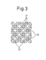
- Fig. 3 is an A-A sectional view of Fig. 2 .
- the carrier of the ammonia oxidation catalyst device 3 is formed of a porous material, such as cordierite, and has many spaces in the axial direction divided by many partition walls 31 extending in the axial direction.
- One of any two neighboring spaces in the axial direction is closed by a plug 32 on the exhaust gas downstream side, and the other one is closed by a plug on the exhaust gas upstream side.
- one of the two neighboring spaces in the axial direction serves as an exhaust gas flow-in passage 33 and the other one serves as an exhaust gas flow-out passage 34, causing the exhaust gas to pass through the partition wall 31 as indicated by arrows in Fig. 2 .
- each partition wall 31 can work as a trapping wall for trapping the particulates.
- Platinum Pt as an oxidation catalyst is carried on both side surfaces of the partition wall 31 by use of alumina.
- the ammonia oxidation catalyst device 3 also functions as the particulate filter, the particulates trapped on the partition wall 31 can be automatically burned by the reaction heat when the ammonia is oxidized. Therefore, in comparison with arranging a particulate filter separately in the exhaust passage, the cost of the exhaust gas purification system can be reduced and it is not necessary that, for example, an oxidation catalyst be arranged on the particulate filter and fuel is supplied to the particulate filter in order to burn the trapped particulates.
Landscapes
- Engineering & Computer Science (AREA)
- Chemical & Material Sciences (AREA)
- Combustion & Propulsion (AREA)
- Mechanical Engineering (AREA)
- General Engineering & Computer Science (AREA)
- Chemical Kinetics & Catalysis (AREA)
- Health & Medical Sciences (AREA)
- Toxicology (AREA)
- Materials Engineering (AREA)
- Exhaust Gas After Treatment (AREA)
- Processes For Solid Components From Exhaust (AREA)
- Exhaust Gas Treatment By Means Of Catalyst (AREA)
Abstract
Description
- The present invention relates to an exhaust purification system of an internal combustion engine.
- In an exhaust system of an internal combustion engine which performs lean combustion such as in a diesel engine, a NOX catalyst device is arranged to purify NOX in the exhaust gas. A known NOX catalyst device produces ammonia by hydrolysis of urea supplied with the exhaust gas and selectively reduces NOX in the exhaust gas by use of the produced ammonia NH3 as a reducing material.
- To decrease ammonia which is not used to reduce NOX in such a selectively reduction type NOX catalyst device and which is released into the atmosphere, it has been suggested that an ammonia oxidation catalyst device be arranged downstream of the selectively reduction type NOX catalyst device.
- However, in such an ammonia oxidation catalyst device, when ammonia is oxidized at a relatively low temperature, dinitrogen monoxide (or nitrous oxide) N2O is produced. It is undesirable to release N2O into the atmosphere. Accordingly, it has been suggested that the temperature of the ammonia oxidation catalyst device be elevated not so as to oxidize ammonia at a relatively low temperature (for example, refer to Japanese Unexamined Patent Publication No.
2008-255899 - If ammonia is oxidized when the temperature of the ammonia oxidation catalyst device is elevated, the amount of produced N2O can be decreased. However, to elevate the temperature of the ammonia oxidation catalyst, fuel, electrical energy, or the like is necessary, and therefore fuel consumption deteriorates as a result.
- Accordingly, an object of the present invention is to provide an exhaust purification system of an internal combustion engine, comprising an ammonia oxidation catalyst device, which can sufficiently decrease an amount of produced N2O without the deterioration of fuel consumption.
- An exhaust purification system of an internal combustion engine as set forth in
claim 1 of the present invention is provided, characterized in that the system comprises an ammonia oxidation catalyst device and an ammonia holding device arranged immediately upstream of the ammonia oxidation catalyst device, the ammonia holding device has a solid acid, holds ammonia to restrain the ammonia from flowing into the ammonia oxidation catalyst device when a temperature of the ammonia oxidation catalyst device is within a N2O producing temperature range, and releases the held ammonia to make the ammonia flow into the ammonia oxidation catalyst device when the temperature of the ammonia oxidation catalyst device is out of the N2O producing temperature range. - An exhaust purification system of an internal combustion engine as set forth in
claim 2 of the present invention is provided as the exhaust purification system of an internal combustion engine as set forth inclaim 1 characterized in that the ammonia oxidation catalyst device has a particulate trapping function. - According to the exhaust purification system of an internal combustion engine as set forth in
claim 1 of the present invention, the system comprises an ammonia oxidation catalyst device and an ammonia holding device arranged immediately upstream of the ammonia oxidation catalyst device. The ammonia holding device has a solid acid and holds ammonia to restrain the ammonia from flowing into the ammonia oxidation catalyst device when a temperature of the ammonia oxidation catalyst device is within a N2O producing temperature range. Therefore, when the temperature of the ammonia oxidation catalyst device is low and is within the N2O producing temperature range, and although the temperature of the ammonia oxidation catalyst device is not elevated without the fuel consumption, a large amount of ammonia is not oxidized and a large amount of N2O is not produced. On the other hand, when the temperature of the ammonia oxidation catalyst device is out of the N2O producing temperature range, the system releases the held ammonia to make the ammonia flow into the ammonia oxidation catalyst device. Therefore, when the temperature of the ammonia oxidation catalyst device becomes high and out of the N2O producing temperature range, an amount of ammonia released from the ammonia holding device can be easily oxidized without the production of a large amount of N2O. Thus, an amount of produced N2O can be sufficiently decreased without the deterioration of fuel consumption. - According to the exhaust purification system of the internal combustion engine as set forth in
claim 2 of the present invention, in the exhaust purification system of an internal combustion engine as set forth inclaim 1, the ammonia oxidation catalyst device has a particulate trapping function. Therefore, the particulates trapped on the ammonia oxidation catalyst device can be automatically burned by the reaction heat when the ammonia is oxidized, and thus it is not necessary that a particulate filter be separately arranged and the temperature thereof be elevated to burn the trapped particulates. -
-
Fig. 1 is a schematic view showing an embodiment of the exhaust purification system of an internal combustion engine according to the present invention. -
Fig. 2 is an enlarged partial vertical sectional view of an ammonia oxidation catalyst device with a particulate trapping function. -
Fig. 3 is an A-A sectional view ofFig. 2 . -
Fig. 4 are graphs slowing changes in an amount of produced N2O and an amount of produced NO according to the temperature of the ammonia oxidation catalyst device. -
Fig. 5 is a graph showing a change in an amount of released ammonia according the temperature of zeolite. -
Fig. 1 is a schematic view showing the exhaust purification system of an internal combustion engine according to the present invention. InFig. 1 ,reference numeral 1 is an exhaust passage of a diesel engine or a direct fuel injection-type spark-ignition engine which performs lean combustion. The exhaust gas of such an engine includes a relatively large amount of NOX so that a NOXcatalyst device 2 for purifying NOX is arranged in theexhaust passage 1. - The NOX
catalyst device 2 is a selectively reducing-type NOX catalyst device which produces ammonia by hydrolysis of urea supplied with the exhaust gas and selectively reduces NOX in the exhaust gas by using of the produced ammonia NH3 as reducing material. - In the case that a selectively reducing type NOX
catalyst device 2 is arranged in theexhaust passage 1, to decrease ammonia which is not used to reduce NOX and is released to the atmosphere, an ammoniaoxidation catalyst device 3 for oxidizing the ammonia is arranged downstream of the selectively reduction type NOXcatalyst device 2. The ammoniaoxidation catalyst device 3 carries, for example, platinum Pt on a monolith carrier by alumina. -
Fig. 4 are graphs slowing an amount of produced N2O (dinitrogen monoxide or nitrous oxide) and an amount of produced NO when ammonia is oxidized by such an ammonia oxidation catalyst device. As shown inFig. 4 , when the temperature of the ammoniaoxidation catalyst device 3 is relatively low as equal to or lower than 350 degrees C and the ammonia is oxidized by it, an amount of produced NO remarkably decreases and an amount of produced N2O remarkably increases. It is undesirable to release N2O into the atmosphere. - In the present embodiment, an
ammonia holding device 4 is arranged immediately upstream of the ammoniaoxidation catalyst device 3. As shown inFig. 1 , theammonia holding device 4 is arranged in a case common to the ammoniaoxidation catalyst device 3. - The
ammonia holding device 4 provides solid acid for holding ammonia on a monolith carrier and, for example, forms a zeolite layer as a solid acid on the monolith carrier, or may be zeolite having a monolith shape. -
Fig. 5 is a graph showing a change in an amount of released ammonia according to the temperature of zeolite. A solid acid, such as zeolite, sufficiently holds ammonia when the temperature thereof is equal to or lower than 350 degrees C and releases the held ammonia when the temperature thereof is over 350 degrees C. - Accordingly, if the
ammonia holding device 4 provided with the zeolite layer is arranged immediately upstream of the ammoniaoxidation catalyst device 3, the temperature of theammonia holding device 4 is equal to about the temperature of the ammoniaoxidation catalyst device 3. Thus, when the temperature of the ammoniaoxidation catalyst device 3 is within a N2O producing temperature range (for example, equal to or lower than 350 degrees C), theammonia holding device 4 sufficiently holds ammonia flowing out from the selectively reducing type NOXcatalyst device 2 and can sufficiently restrain the ammonia from flowing into the ammoniaoxidation catalyst device 3. - When the temperature of the ammonia
oxidation catalyst device 3 is out of the N2O producing temperature range (for example, higher than 350 degrees C), theammonia holding device 4 releases the held ammonia and makes the ammonia flow into the ammoniaoxidation catalyst device 3. In this case, when the ammonia is oxidized in the ammoniaoxidation catalyst device 3, N2O is not easily produced, but NO or N2 is easily produced. Thus, an amount of N2O produced when ammonia is oxidized can be sufficiently decreased especially without the elevation of the temperature of the ammoniaoxidation catalyst device 3. - If the
ammonia holding device 4 has any solid acid, which is not limited to zeolite, it can hold ammonia within the N2O producing temperature range and can releases the ammonia out of the N2O producing temperature range. Solid acid such as for example, titania, zirconia, or silica may be carried on the monolith carrier by alumina. - Incidentally, particulates are included in the exhaust gas of a diesel engine and a particulate filter may be arranged in the
exhaust passage 1 to restrain the particulates from being emitted into the atmosphere. Accordingly, the ammoniaoxidation catalyst device 3 may function as the particulate filter.Fig. 2 is an enlarged partial vertical sectional view of the ammoniaoxidation catalyst device 3 with a particulate trapping function.Fig. 3 is an A-A sectional view ofFig. 2 . - As shown in
Figs. 2 and3 , the carrier of the ammoniaoxidation catalyst device 3 is formed of a porous material, such as cordierite, and has many spaces in the axial direction divided bymany partition walls 31 extending in the axial direction. One of any two neighboring spaces in the axial direction is closed by aplug 32 on the exhaust gas downstream side, and the other one is closed by a plug on the exhaust gas upstream side. Thus, one of the two neighboring spaces in the axial direction serves as an exhaust gas flow-inpassage 33 and the other one serves as an exhaust gas flow-outpassage 34, causing the exhaust gas to pass through thepartition wall 31 as indicated by arrows inFig. 2 . The particulates in the exhaust gas are much smaller than the pores of thepartition wall 31, but collide with and are trapped on the exhaust gas upstream side surface of thepartition wall 31 and the pores surface in thepartition wall 31. Thus, eachpartition wall 31 can work as a trapping wall for trapping the particulates. Platinum Pt as an oxidation catalyst is carried on both side surfaces of thepartition wall 31 by use of alumina. - In this way, if the ammonia
oxidation catalyst device 3 also functions as the particulate filter, the particulates trapped on thepartition wall 31 can be automatically burned by the reaction heat when the ammonia is oxidized. Therefore, in comparison with arranging a particulate filter separately in the exhaust passage, the cost of the exhaust gas purification system can be reduced and it is not necessary that, for example, an oxidation catalyst be arranged on the particulate filter and fuel is supplied to the particulate filter in order to burn the trapped particulates. -
- 1: exhaust passage
- 2: NOX catalyst device
- 3: ammonia oxidation catalyst device
- 4: ammonia holding device
Claims (2)
- An exhaust purification system of an internal combustion engine, characterized in that said system comprises an ammonia oxidation catalyst device and an ammonia holding device arranged immediately upstream of said ammonia oxidation catalyst device, said ammonia holding device has a solid acid, holds ammonia to restrain the ammonia from flowing into said ammonia oxidation catalyst device when a temperature of said ammonia oxidation catalyst device is within a N2O producing temperature range, and releases the held ammonia to make the ammonia flow into said ammonia oxidation catalyst device when the temperature of said ammonia oxidation catalyst device is out of the N2O producing temperature range.
- An exhaust purification system of an internal combustion engine according to claim 1, characterized in that said ammonia oxidation catalyst device has a particulate trapping function.
Applications Claiming Priority (1)
| Application Number | Priority Date | Filing Date | Title |
|---|---|---|---|
| PCT/JP2009/061269 WO2010146720A1 (en) | 2009-06-16 | 2009-06-16 | Exhaust purifier of internal combustion engine |
Publications (3)
| Publication Number | Publication Date |
|---|---|
| EP2444611A1 true EP2444611A1 (en) | 2012-04-25 |
| EP2444611A4 EP2444611A4 (en) | 2014-12-10 |
| EP2444611B1 EP2444611B1 (en) | 2016-01-13 |
Family
ID=43356058
Family Applications (1)
| Application Number | Title | Priority Date | Filing Date |
|---|---|---|---|
| EP09846213.8A Not-in-force EP2444611B1 (en) | 2009-06-16 | 2009-06-16 | Exhaust purification system of an internal combustion engine |
Country Status (5)
| Country | Link |
|---|---|
| US (1) | US9109492B2 (en) |
| EP (1) | EP2444611B1 (en) |
| JP (1) | JP5310851B2 (en) |
| CN (1) | CN102482969B (en) |
| WO (1) | WO2010146720A1 (en) |
Families Citing this family (4)
| Publication number | Priority date | Publication date | Assignee | Title |
|---|---|---|---|---|
| EP2726177B1 (en) * | 2011-07-01 | 2016-01-06 | Toyota Jidosha Kabushiki Kaisha | Exhaust purification system for internal combustion engine |
| US20140165560A1 (en) * | 2012-12-18 | 2014-06-19 | Cummins Ip, Inc. | Low pressure egr ammonia oxidation catalyst |
| US8883102B1 (en) * | 2014-01-14 | 2014-11-11 | Ford Global Technologies, Llc | Methods for controlling nitrous oxide emissions |
| US9975543B1 (en) | 2017-04-04 | 2018-05-22 | Cummins Emission Solutions Inc. | Systems and methods for waste heat utilization in combustion-electric propulsion systems |
Family Cites Families (36)
| Publication number | Priority date | Publication date | Assignee | Title |
|---|---|---|---|---|
| JP2967113B2 (en) * | 1991-06-12 | 1999-10-25 | 株式会社豊田中央研究所 | Exhaust gas purification method |
| JP3321806B2 (en) * | 1995-11-17 | 2002-09-09 | トヨタ自動車株式会社 | Method and apparatus for purifying exhaust of an internal combustion engine |
| FR2789911B1 (en) * | 1999-02-18 | 2001-05-04 | Grande Paroisse Sa | PROCESS FOR SIMULTANEOUSLY KILLING NITRIC OXIDES AND NITROGEN PROTOXIDE IN THE GASES CONTAINING THE SAME |
| JP4352516B2 (en) * | 1999-08-03 | 2009-10-28 | トヨタ自動車株式会社 | Exhaust gas purification device for internal combustion engine |
| DE10001539B4 (en) * | 2000-01-14 | 2006-01-19 | Uhde Gmbh | Process for the removal of NOx and N2O |
| US7438878B2 (en) * | 2001-03-12 | 2008-10-21 | Basf Catalysts Llc | Selective catalytic reduction of N2O |
| DE10112444A1 (en) * | 2001-03-13 | 2002-10-02 | Krupp Uhde Gmbh | Reducing the nitrogen oxide and nitrous oxide content of a gas comprises adding a gaseous reducing agent and contacting the gas with an iron-loaded zeolite catalyst |
| DE10226461A1 (en) * | 2002-06-13 | 2004-01-22 | Uhde Gmbh | Method and apparatus for reducing the content of NOx and N2O in gases |
| JP4300862B2 (en) * | 2002-11-11 | 2009-07-22 | トヨタ自動車株式会社 | Exhaust gas purification device for internal combustion engine |
| US6947831B2 (en) * | 2003-04-11 | 2005-09-20 | Ford Global Technologies, Llc | Pressure sensor diagnosis via a computer |
| JP2005061362A (en) | 2003-08-19 | 2005-03-10 | Hino Motors Ltd | Exhaust purification equipment |
| DE60307291T2 (en) * | 2003-11-26 | 2007-10-18 | Ford Global Technologies, LLC, Dearborn | Device and method for removing by-products from the exhaust gas of an internal combustion engine |
| JP4427356B2 (en) * | 2004-02-27 | 2010-03-03 | 東京濾器株式会社 | Nitrogen oxide purification catalyst system and nitrogen oxide purification method |
| JP2006022729A (en) * | 2004-07-08 | 2006-01-26 | Hino Motors Ltd | Exhaust purification device control method |
| DE102005012568A1 (en) * | 2005-03-18 | 2006-09-21 | Daimlerchrysler Ag | Device for removing nitrogen oxides from engine exhaust gas and method for metering an additive for engine exhaust gas |
| US7827782B2 (en) * | 2005-05-19 | 2010-11-09 | Ford Global Technologies, Llc | Method for remediating emissions |
| JP4729990B2 (en) * | 2005-06-10 | 2011-07-20 | トヨタ自動車株式会社 | Exhaust gas purification device for internal combustion engine |
| JP4789242B2 (en) * | 2005-12-09 | 2011-10-12 | Udトラックス株式会社 | Exhaust purification device |
| DE502007003465D1 (en) | 2007-02-23 | 2010-05-27 | Umicore Ag & Co Kg | Catalytically activated diesel particulate filter with ammonia barrier effect |
| MX2009009095A (en) * | 2007-02-27 | 2009-09-14 | Basf Catalysts Llc | ZEOLITA CHA COPPER CATALYSTS. |
| JP2007239752A (en) * | 2007-03-30 | 2007-09-20 | Toyota Motor Corp | Exhaust gas purification device for internal combustion engine |
| JP4706659B2 (en) | 2007-04-05 | 2011-06-22 | トヨタ自動車株式会社 | Method for estimating N2O generation amount in ammonia oxidation catalyst and exhaust gas purification system for internal combustion engine |
| DE102007060623B4 (en) * | 2007-12-15 | 2011-04-14 | Umicore Ag & Co. Kg | Denitrification of diesel engine exhaust gases using a tempered pre-catalyst for on-demand NO2 provision |
| JP5459965B2 (en) * | 2008-02-05 | 2014-04-02 | メタウォーター株式会社 | Method for removing N2O in exhaust gas |
| WO2009128169A1 (en) * | 2008-04-18 | 2009-10-22 | 本田技研工業株式会社 | Exhaust purification apparatus for internal combustion engine |
| US8506893B2 (en) * | 2008-04-23 | 2013-08-13 | Ford Global Technologies, Llc | Selective catalytic reduction catalyst system with expanded temperature window |
| US20100050604A1 (en) * | 2008-08-28 | 2010-03-04 | John William Hoard | SCR-LNT CATALYST COMBINATION FOR IMPROVED NOx CONTROL OF LEAN GASOLINE AND DIESEL ENGINES |
| US8448424B2 (en) * | 2009-01-16 | 2013-05-28 | Ford Global Technologies, Llc. | Emission control system with an integrated particulate filter and selective catalytic reduction unit |
| JP5254845B2 (en) * | 2009-03-03 | 2013-08-07 | 本田技研工業株式会社 | Exhaust purification device |
| JP2010229820A (en) * | 2009-03-25 | 2010-10-14 | Nippon Soken Inc | Exhaust gas purification device for internal combustion engine |
| WO2010146717A1 (en) * | 2009-06-15 | 2010-12-23 | トヨタ自動車株式会社 | Exhaust cleaner for internal combustion engine |
| US8333062B2 (en) * | 2009-06-29 | 2012-12-18 | GM Global Technology Operations LLC | Method for monitoring ammonia storage in an exhaust aftertreatment system |
| US8491845B2 (en) * | 2009-09-10 | 2013-07-23 | Cummins Ip, Inc. | Low temperature selective catalytic reduction catalyst and associated systems and methods |
| DE102010014468B4 (en) * | 2010-04-09 | 2013-10-31 | Umicore Ag & Co. Kg | Process for the reduction of nitrous oxide in the exhaust aftertreatment of lean burn engines |
| WO2013022517A1 (en) * | 2011-08-09 | 2013-02-14 | International Engine Intellectual Property Company, Llc | Method and system for reducing nox in engine exhaust using a cooling element |
| US20130312392A1 (en) * | 2012-05-23 | 2013-11-28 | Cary Henry | Systems and methods to mitigate nox and hc emissions at low exhaust temperatures |
-
2009
- 2009-06-16 US US13/318,973 patent/US9109492B2/en not_active Expired - Fee Related
- 2009-06-16 WO PCT/JP2009/061269 patent/WO2010146720A1/en not_active Ceased
- 2009-06-16 EP EP09846213.8A patent/EP2444611B1/en not_active Not-in-force
- 2009-06-16 JP JP2011519395A patent/JP5310851B2/en not_active Expired - Fee Related
- 2009-06-16 CN CN200980159602.9A patent/CN102482969B/en not_active Expired - Fee Related
Also Published As
| Publication number | Publication date |
|---|---|
| US9109492B2 (en) | 2015-08-18 |
| JPWO2010146720A1 (en) | 2012-11-29 |
| CN102482969A (en) | 2012-05-30 |
| WO2010146720A1 (en) | 2010-12-23 |
| CN102482969B (en) | 2014-05-28 |
| JP5310851B2 (en) | 2013-10-09 |
| EP2444611B1 (en) | 2016-01-13 |
| EP2444611A4 (en) | 2014-12-10 |
| US20120073273A1 (en) | 2012-03-29 |
Similar Documents
| Publication | Publication Date | Title |
|---|---|---|
| US8679412B2 (en) | Exhaust gas-purifying system | |
| ES2688995T3 (en) | Enhanced catalyzed soot filter | |
| KR102292153B1 (en) | Three-way catalytic converter | |
| KR102149735B1 (en) | Close-coupled scr system | |
| US11420189B2 (en) | Exhaust gas purification catalyst | |
| CN102057139B (en) | Exhaust gas purification device and exhaust gas purification system | |
| RU2018126874A (en) | GASOLINE SOLID PARTICLE FILTER | |
| CN107288728A (en) | Catalyst | |
| CN106102870A (en) | Comprise the catalysis system for gasoline engine of ternary catalyzing unit and SCR catalyst | |
| US10107162B2 (en) | Catalyst subassembly, device comprising same for purifying exhaust gases from an internal combustion engine, modular system for the subassembly, and method for manufacturing the subassembly | |
| CN112770836B (en) | Exhaust gas purification systems for gasoline engines | |
| US20130302214A1 (en) | Coated diesel particle filter | |
| JP2017104825A (en) | Catalytic converter | |
| CN109310991B (en) | Diesel oxidation catalytic converter | |
| EP1707774B1 (en) | Particulate matter-containing exhaust emission controlling filter, exhaust emission controlling method and device | |
| US9109492B2 (en) | Exhaust purification system of internal combustion engine | |
| JP7130622B2 (en) | Exhaust gas purification catalyst | |
| JP2010242515A (en) | Exhaust gas purification system and exhaust gas purification method | |
| RU2012121578A (en) | METHOD AND APPARATUS FOR CLEANING EXHAUST GAS OF INTERNAL COMBUSTION ENGINE | |
| KR101022018B1 (en) | Exhaust gas purification system of engine and marine engine comprising same | |
| JP4582806B2 (en) | Exhaust gas purification device | |
| US9708949B2 (en) | Exhaust aftertreatment system for a compression-ignition engine | |
| JP2019035340A (en) | Exhaust emission control system | |
| JP2010013969A (en) | Exhaust emission control device | |
| JP2012159053A (en) | Exhaust gas purification apparatus |
Legal Events
| Date | Code | Title | Description |
|---|---|---|---|
| PUAI | Public reference made under article 153(3) epc to a published international application that has entered the european phase |
Free format text: ORIGINAL CODE: 0009012 |
|
| 17P | Request for examination filed |
Effective date: 20120116 |
|
| AK | Designated contracting states |
Kind code of ref document: A1 Designated state(s): AT BE BG CH CY CZ DE DK EE ES FI FR GB GR HR HU IE IS IT LI LT LU LV MC MK MT NL NO PL PT RO SE SI SK TR |
|
| DAX | Request for extension of the european patent (deleted) | ||
| RAP1 | Party data changed (applicant data changed or rights of an application transferred) |
Owner name: TOYOTA JIDOSHA KABUSHIKI KAISHA |
|
| RIN1 | Information on inventor provided before grant (corrected) |
Inventor name: UMEMOTO, KAZUHIRO Inventor name: ASANUMA, TAKAMITSU |
|
| A4 | Supplementary search report drawn up and despatched |
Effective date: 20141111 |
|
| RIC1 | Information provided on ipc code assigned before grant |
Ipc: F01N 3/20 20060101ALI20141105BHEP Ipc: F01N 3/035 20060101ALI20141105BHEP Ipc: F01N 3/10 20060101ALI20141105BHEP Ipc: F01N 3/08 20060101AFI20141105BHEP Ipc: F01N 3/24 20060101ALI20141105BHEP |
|
| REG | Reference to a national code |
Ref country code: DE Ref legal event code: R079 Ref document number: 602009035903 Country of ref document: DE Free format text: PREVIOUS MAIN CLASS: F01N0003080000 Ipc: F01N0013000000 |
|
| RIC1 | Information provided on ipc code assigned before grant |
Ipc: F01N 13/00 20100101AFI20150615BHEP Ipc: F01N 3/08 20060101ALI20150615BHEP Ipc: F01N 3/10 20060101ALI20150615BHEP Ipc: F01N 3/035 20060101ALI20150615BHEP Ipc: F01N 3/20 20060101ALI20150615BHEP |
|
| GRAP | Despatch of communication of intention to grant a patent |
Free format text: ORIGINAL CODE: EPIDOSNIGR1 |
|
| INTG | Intention to grant announced |
Effective date: 20150807 |
|
| GRAS | Grant fee paid |
Free format text: ORIGINAL CODE: EPIDOSNIGR3 |
|
| GRAA | (expected) grant |
Free format text: ORIGINAL CODE: 0009210 |
|
| AK | Designated contracting states |
Kind code of ref document: B1 Designated state(s): AT BE BG CH CY CZ DE DK EE ES FI FR GB GR HR HU IE IS IT LI LT LU LV MC MK MT NL NO PL PT RO SE SI SK TR |
|
| REG | Reference to a national code |
Ref country code: GB Ref legal event code: FG4D |
|
| REG | Reference to a national code |
Ref country code: CH Ref legal event code: EP |
|
| REG | Reference to a national code |
Ref country code: IE Ref legal event code: FG4D |
|
| REG | Reference to a national code |
Ref country code: AT Ref legal event code: REF Ref document number: 770679 Country of ref document: AT Kind code of ref document: T Effective date: 20160215 |
|
| REG | Reference to a national code |
Ref country code: DE Ref legal event code: R096 Ref document number: 602009035903 Country of ref document: DE |
|
| REG | Reference to a national code |
Ref country code: DE Ref legal event code: R084 Ref document number: 602009035903 Country of ref document: DE |
|
| REG | Reference to a national code |
Ref country code: LT Ref legal event code: MG4D |
|
| REG | Reference to a national code |
Ref country code: NL Ref legal event code: MP Effective date: 20160113 |
|
| REG | Reference to a national code |
Ref country code: AT Ref legal event code: MK05 Ref document number: 770679 Country of ref document: AT Kind code of ref document: T Effective date: 20160113 |
|
| PG25 | Lapsed in a contracting state [announced via postgrant information from national office to epo] |
Ref country code: NL Free format text: LAPSE BECAUSE OF FAILURE TO SUBMIT A TRANSLATION OF THE DESCRIPTION OR TO PAY THE FEE WITHIN THE PRESCRIBED TIME-LIMIT Effective date: 20160113 |
|
| PG25 | Lapsed in a contracting state [announced via postgrant information from national office to epo] |
Ref country code: IT Free format text: LAPSE BECAUSE OF FAILURE TO SUBMIT A TRANSLATION OF THE DESCRIPTION OR TO PAY THE FEE WITHIN THE PRESCRIBED TIME-LIMIT Effective date: 20160113 Ref country code: GR Free format text: LAPSE BECAUSE OF FAILURE TO SUBMIT A TRANSLATION OF THE DESCRIPTION OR TO PAY THE FEE WITHIN THE PRESCRIBED TIME-LIMIT Effective date: 20160414 Ref country code: ES Free format text: LAPSE BECAUSE OF FAILURE TO SUBMIT A TRANSLATION OF THE DESCRIPTION OR TO PAY THE FEE WITHIN THE PRESCRIBED TIME-LIMIT Effective date: 20160113 Ref country code: FI Free format text: LAPSE BECAUSE OF FAILURE TO SUBMIT A TRANSLATION OF THE DESCRIPTION OR TO PAY THE FEE WITHIN THE PRESCRIBED TIME-LIMIT Effective date: 20160113 Ref country code: NO Free format text: LAPSE BECAUSE OF FAILURE TO SUBMIT A TRANSLATION OF THE DESCRIPTION OR TO PAY THE FEE WITHIN THE PRESCRIBED TIME-LIMIT Effective date: 20160413 Ref country code: HR Free format text: LAPSE BECAUSE OF FAILURE TO SUBMIT A TRANSLATION OF THE DESCRIPTION OR TO PAY THE FEE WITHIN THE PRESCRIBED TIME-LIMIT Effective date: 20160113 |
|
| PG25 | Lapsed in a contracting state [announced via postgrant information from national office to epo] |
Ref country code: LT Free format text: LAPSE BECAUSE OF FAILURE TO SUBMIT A TRANSLATION OF THE DESCRIPTION OR TO PAY THE FEE WITHIN THE PRESCRIBED TIME-LIMIT Effective date: 20160113 Ref country code: LV Free format text: LAPSE BECAUSE OF FAILURE TO SUBMIT A TRANSLATION OF THE DESCRIPTION OR TO PAY THE FEE WITHIN THE PRESCRIBED TIME-LIMIT Effective date: 20160113 Ref country code: IS Free format text: LAPSE BECAUSE OF FAILURE TO SUBMIT A TRANSLATION OF THE DESCRIPTION OR TO PAY THE FEE WITHIN THE PRESCRIBED TIME-LIMIT Effective date: 20160513 Ref country code: AT Free format text: LAPSE BECAUSE OF FAILURE TO SUBMIT A TRANSLATION OF THE DESCRIPTION OR TO PAY THE FEE WITHIN THE PRESCRIBED TIME-LIMIT Effective date: 20160113 Ref country code: PL Free format text: LAPSE BECAUSE OF FAILURE TO SUBMIT A TRANSLATION OF THE DESCRIPTION OR TO PAY THE FEE WITHIN THE PRESCRIBED TIME-LIMIT Effective date: 20160113 Ref country code: SE Free format text: LAPSE BECAUSE OF FAILURE TO SUBMIT A TRANSLATION OF THE DESCRIPTION OR TO PAY THE FEE WITHIN THE PRESCRIBED TIME-LIMIT Effective date: 20160113 Ref country code: PT Free format text: LAPSE BECAUSE OF FAILURE TO SUBMIT A TRANSLATION OF THE DESCRIPTION OR TO PAY THE FEE WITHIN THE PRESCRIBED TIME-LIMIT Effective date: 20160513 |
|
| REG | Reference to a national code |
Ref country code: DE Ref legal event code: R097 Ref document number: 602009035903 Country of ref document: DE |
|
| PG25 | Lapsed in a contracting state [announced via postgrant information from national office to epo] |
Ref country code: EE Free format text: LAPSE BECAUSE OF FAILURE TO SUBMIT A TRANSLATION OF THE DESCRIPTION OR TO PAY THE FEE WITHIN THE PRESCRIBED TIME-LIMIT Effective date: 20160113 Ref country code: DK Free format text: LAPSE BECAUSE OF FAILURE TO SUBMIT A TRANSLATION OF THE DESCRIPTION OR TO PAY THE FEE WITHIN THE PRESCRIBED TIME-LIMIT Effective date: 20160113 |
|
| PLBE | No opposition filed within time limit |
Free format text: ORIGINAL CODE: 0009261 |
|
| STAA | Information on the status of an ep patent application or granted ep patent |
Free format text: STATUS: NO OPPOSITION FILED WITHIN TIME LIMIT |
|
| PG25 | Lapsed in a contracting state [announced via postgrant information from national office to epo] |
Ref country code: SK Free format text: LAPSE BECAUSE OF FAILURE TO SUBMIT A TRANSLATION OF THE DESCRIPTION OR TO PAY THE FEE WITHIN THE PRESCRIBED TIME-LIMIT Effective date: 20160113 Ref country code: RO Free format text: LAPSE BECAUSE OF FAILURE TO SUBMIT A TRANSLATION OF THE DESCRIPTION OR TO PAY THE FEE WITHIN THE PRESCRIBED TIME-LIMIT Effective date: 20160113 Ref country code: CZ Free format text: LAPSE BECAUSE OF FAILURE TO SUBMIT A TRANSLATION OF THE DESCRIPTION OR TO PAY THE FEE WITHIN THE PRESCRIBED TIME-LIMIT Effective date: 20160113 |
|
| 26N | No opposition filed |
Effective date: 20161014 |
|
| PG25 | Lapsed in a contracting state [announced via postgrant information from national office to epo] |
Ref country code: BE Free format text: LAPSE BECAUSE OF FAILURE TO SUBMIT A TRANSLATION OF THE DESCRIPTION OR TO PAY THE FEE WITHIN THE PRESCRIBED TIME-LIMIT Effective date: 20160113 |
|
| PG25 | Lapsed in a contracting state [announced via postgrant information from national office to epo] |
Ref country code: MC Free format text: LAPSE BECAUSE OF FAILURE TO SUBMIT A TRANSLATION OF THE DESCRIPTION OR TO PAY THE FEE WITHIN THE PRESCRIBED TIME-LIMIT Effective date: 20160113 |
|
| REG | Reference to a national code |
Ref country code: CH Ref legal event code: PL |
|
| PG25 | Lapsed in a contracting state [announced via postgrant information from national office to epo] |
Ref country code: SI Free format text: LAPSE BECAUSE OF FAILURE TO SUBMIT A TRANSLATION OF THE DESCRIPTION OR TO PAY THE FEE WITHIN THE PRESCRIBED TIME-LIMIT Effective date: 20160113 Ref country code: BG Free format text: LAPSE BECAUSE OF FAILURE TO SUBMIT A TRANSLATION OF THE DESCRIPTION OR TO PAY THE FEE WITHIN THE PRESCRIBED TIME-LIMIT Effective date: 20160413 |
|
| GBPC | Gb: european patent ceased through non-payment of renewal fee |
Effective date: 20160616 |
|
| REG | Reference to a national code |
Ref country code: IE Ref legal event code: MM4A |
|
| REG | Reference to a national code |
Ref country code: FR Ref legal event code: ST Effective date: 20170228 |
|
| PG25 | Lapsed in a contracting state [announced via postgrant information from national office to epo] |
Ref country code: LI Free format text: LAPSE BECAUSE OF NON-PAYMENT OF DUE FEES Effective date: 20160630 Ref country code: FR Free format text: LAPSE BECAUSE OF NON-PAYMENT OF DUE FEES Effective date: 20160630 Ref country code: CH Free format text: LAPSE BECAUSE OF NON-PAYMENT OF DUE FEES Effective date: 20160630 |
|
| PG25 | Lapsed in a contracting state [announced via postgrant information from national office to epo] |
Ref country code: IE Free format text: LAPSE BECAUSE OF NON-PAYMENT OF DUE FEES Effective date: 20160616 Ref country code: GB Free format text: LAPSE BECAUSE OF NON-PAYMENT OF DUE FEES Effective date: 20160616 |
|
| PG25 | Lapsed in a contracting state [announced via postgrant information from national office to epo] |
Ref country code: HU Free format text: LAPSE BECAUSE OF FAILURE TO SUBMIT A TRANSLATION OF THE DESCRIPTION OR TO PAY THE FEE WITHIN THE PRESCRIBED TIME-LIMIT; INVALID AB INITIO Effective date: 20090616 Ref country code: CY Free format text: LAPSE BECAUSE OF FAILURE TO SUBMIT A TRANSLATION OF THE DESCRIPTION OR TO PAY THE FEE WITHIN THE PRESCRIBED TIME-LIMIT Effective date: 20160113 |
|
| PG25 | Lapsed in a contracting state [announced via postgrant information from national office to epo] |
Ref country code: MK Free format text: LAPSE BECAUSE OF FAILURE TO SUBMIT A TRANSLATION OF THE DESCRIPTION OR TO PAY THE FEE WITHIN THE PRESCRIBED TIME-LIMIT Effective date: 20160113 Ref country code: MT Free format text: LAPSE BECAUSE OF NON-PAYMENT OF DUE FEES Effective date: 20160630 Ref country code: TR Free format text: LAPSE BECAUSE OF FAILURE TO SUBMIT A TRANSLATION OF THE DESCRIPTION OR TO PAY THE FEE WITHIN THE PRESCRIBED TIME-LIMIT Effective date: 20160113 Ref country code: LU Free format text: LAPSE BECAUSE OF NON-PAYMENT OF DUE FEES Effective date: 20160616 |
|
| PGFP | Annual fee paid to national office [announced via postgrant information from national office to epo] |
Ref country code: DE Payment date: 20220420 Year of fee payment: 14 |
|
| P01 | Opt-out of the competence of the unified patent court (upc) registered |
Effective date: 20230427 |
|
| REG | Reference to a national code |
Ref country code: DE Ref legal event code: R119 Ref document number: 602009035903 Country of ref document: DE |
|
| PG25 | Lapsed in a contracting state [announced via postgrant information from national office to epo] |
Ref country code: DE Free format text: LAPSE BECAUSE OF NON-PAYMENT OF DUE FEES Effective date: 20240103 |