EP2444000A1 - Ultrasound System for Adjusting Ultrasonic Beam Direction and Method for Operating Ultrasound System - Google Patents
Ultrasound System for Adjusting Ultrasonic Beam Direction and Method for Operating Ultrasound System Download PDFInfo
- Publication number
- EP2444000A1 EP2444000A1 EP11163082A EP11163082A EP2444000A1 EP 2444000 A1 EP2444000 A1 EP 2444000A1 EP 11163082 A EP11163082 A EP 11163082A EP 11163082 A EP11163082 A EP 11163082A EP 2444000 A1 EP2444000 A1 EP 2444000A1
- Authority
- EP
- European Patent Office
- Prior art keywords
- ultrasonic beam
- angle
- probe
- ultrasound system
- reflection
- Prior art date
- Legal status (The legal status is an assumption and is not a legal conclusion. Google has not performed a legal analysis and makes no representation as to the accuracy of the status listed.)
- Withdrawn
Links
Images


Classifications
-
- A—HUMAN NECESSITIES
- A61—MEDICAL OR VETERINARY SCIENCE; HYGIENE
- A61B—DIAGNOSIS; SURGERY; IDENTIFICATION
- A61B8/00—Diagnosis using ultrasonic, sonic or infrasonic waves
- A61B8/08—Clinical applications
-
- A—HUMAN NECESSITIES
- A61—MEDICAL OR VETERINARY SCIENCE; HYGIENE
- A61B—DIAGNOSIS; SURGERY; IDENTIFICATION
- A61B8/00—Diagnosis using ultrasonic, sonic or infrasonic waves
- A61B8/13—Tomography
- A61B8/14—Echo-tomography
-
- A—HUMAN NECESSITIES
- A61—MEDICAL OR VETERINARY SCIENCE; HYGIENE
- A61B—DIAGNOSIS; SURGERY; IDENTIFICATION
- A61B8/00—Diagnosis using ultrasonic, sonic or infrasonic waves
- A61B8/52—Devices using data or image processing specially adapted for diagnosis using ultrasonic, sonic or infrasonic waves
- A61B8/5215—Devices using data or image processing specially adapted for diagnosis using ultrasonic, sonic or infrasonic waves involving processing of medical diagnostic data
-
- G—PHYSICS
- G01—MEASURING; TESTING
- G01N—INVESTIGATING OR ANALYSING MATERIALS BY DETERMINING THEIR CHEMICAL OR PHYSICAL PROPERTIES
- G01N29/00—Investigating or analysing materials by the use of ultrasonic, sonic or infrasonic waves; Visualisation of the interior of objects by transmitting ultrasonic or sonic waves through the object
- G01N29/22—Details, e.g. general constructional or apparatus details
- G01N29/221—Arrangements for directing or focusing the acoustical waves
-
- G—PHYSICS
- G01—MEASURING; TESTING
- G01N—INVESTIGATING OR ANALYSING MATERIALS BY DETERMINING THEIR CHEMICAL OR PHYSICAL PROPERTIES
- G01N29/00—Investigating or analysing materials by the use of ultrasonic, sonic or infrasonic waves; Visualisation of the interior of objects by transmitting ultrasonic or sonic waves through the object
- G01N29/22—Details, e.g. general constructional or apparatus details
- G01N29/24—Probes
- G01N29/2487—Directing probes, e.g. angle probes
-
- G—PHYSICS
- G01—MEASURING; TESTING
- G01N—INVESTIGATING OR ANALYSING MATERIALS BY DETERMINING THEIR CHEMICAL OR PHYSICAL PROPERTIES
- G01N29/00—Investigating or analysing materials by the use of ultrasonic, sonic or infrasonic waves; Visualisation of the interior of objects by transmitting ultrasonic or sonic waves through the object
- G01N29/44—Processing the detected response signal, e.g. electronic circuits specially adapted therefor
-
- G—PHYSICS
- G01—MEASURING; TESTING
- G01S—RADIO DIRECTION-FINDING; RADIO NAVIGATION; DETERMINING DISTANCE OR VELOCITY BY USE OF RADIO WAVES; LOCATING OR PRESENCE-DETECTING BY USE OF THE REFLECTION OR RERADIATION OF RADIO WAVES; ANALOGOUS ARRANGEMENTS USING OTHER WAVES
- G01S15/00—Systems using the reflection or reradiation of acoustic waves, e.g. sonar systems
- G01S15/88—Sonar systems specially adapted for specific applications
- G01S15/89—Sonar systems specially adapted for specific applications for mapping or imaging
- G01S15/8906—Short-range imaging systems; Acoustic microscope systems using pulse-echo techniques
- G01S15/8995—Combining images from different aspect angles, e.g. spatial compounding
-
- G—PHYSICS
- G01—MEASURING; TESTING
- G01S—RADIO DIRECTION-FINDING; RADIO NAVIGATION; DETERMINING DISTANCE OR VELOCITY BY USE OF RADIO WAVES; LOCATING OR PRESENCE-DETECTING BY USE OF THE REFLECTION OR RERADIATION OF RADIO WAVES; ANALOGOUS ARRANGEMENTS USING OTHER WAVES
- G01S7/00—Details of systems according to groups G01S13/00, G01S15/00, G01S17/00
- G01S7/52—Details of systems according to groups G01S13/00, G01S15/00, G01S17/00 of systems according to group G01S15/00
- G01S7/52017—Details of systems according to groups G01S13/00, G01S15/00, G01S17/00 of systems according to group G01S15/00 particularly adapted to short-range imaging
- G01S7/52023—Details of receivers
- G01S7/52025—Details of receivers for pulse systems
- G01S7/52026—Extracting wanted echo signals
-
- G—PHYSICS
- G01—MEASURING; TESTING
- G01S—RADIO DIRECTION-FINDING; RADIO NAVIGATION; DETERMINING DISTANCE OR VELOCITY BY USE OF RADIO WAVES; LOCATING OR PRESENCE-DETECTING BY USE OF THE REFLECTION OR RERADIATION OF RADIO WAVES; ANALOGOUS ARRANGEMENTS USING OTHER WAVES
- G01S7/00—Details of systems according to groups G01S13/00, G01S15/00, G01S17/00
- G01S7/52—Details of systems according to groups G01S13/00, G01S15/00, G01S17/00 of systems according to group G01S15/00
- G01S7/52017—Details of systems according to groups G01S13/00, G01S15/00, G01S17/00 of systems according to group G01S15/00 particularly adapted to short-range imaging
- G01S7/52023—Details of receivers
- G01S7/52036—Details of receivers using analysis of echo signal for target characterisation
-
- G—PHYSICS
- G01—MEASURING; TESTING
- G01S—RADIO DIRECTION-FINDING; RADIO NAVIGATION; DETERMINING DISTANCE OR VELOCITY BY USE OF RADIO WAVES; LOCATING OR PRESENCE-DETECTING BY USE OF THE REFLECTION OR RERADIATION OF RADIO WAVES; ANALOGOUS ARRANGEMENTS USING OTHER WAVES
- G01S7/00—Details of systems according to groups G01S13/00, G01S15/00, G01S17/00
- G01S7/52—Details of systems according to groups G01S13/00, G01S15/00, G01S17/00 of systems according to group G01S15/00
- G01S7/52017—Details of systems according to groups G01S13/00, G01S15/00, G01S17/00 of systems according to group G01S15/00 particularly adapted to short-range imaging
- G01S7/52046—Techniques for image enhancement involving transmitter or receiver
- G01S7/52047—Techniques for image enhancement involving transmitter or receiver for elimination of side lobes or of grating lobes; for increasing resolving power
-
- G—PHYSICS
- G01—MEASURING; TESTING
- G01S—RADIO DIRECTION-FINDING; RADIO NAVIGATION; DETERMINING DISTANCE OR VELOCITY BY USE OF RADIO WAVES; LOCATING OR PRESENCE-DETECTING BY USE OF THE REFLECTION OR RERADIATION OF RADIO WAVES; ANALOGOUS ARRANGEMENTS USING OTHER WAVES
- G01S7/00—Details of systems according to groups G01S13/00, G01S15/00, G01S17/00
- G01S7/52—Details of systems according to groups G01S13/00, G01S15/00, G01S17/00 of systems according to group G01S15/00
- G01S7/52017—Details of systems according to groups G01S13/00, G01S15/00, G01S17/00 of systems according to group G01S15/00 particularly adapted to short-range imaging
- G01S7/5205—Means for monitoring or calibrating
-
- G—PHYSICS
- G16—INFORMATION AND COMMUNICATION TECHNOLOGY [ICT] SPECIALLY ADAPTED FOR SPECIFIC APPLICATION FIELDS
- G16H—HEALTHCARE INFORMATICS, i.e. INFORMATION AND COMMUNICATION TECHNOLOGY [ICT] SPECIALLY ADAPTED FOR THE HANDLING OR PROCESSING OF MEDICAL OR HEALTHCARE DATA
- G16H50/00—ICT specially adapted for medical diagnosis, medical simulation or medical data mining; ICT specially adapted for detecting, monitoring or modelling epidemics or pandemics
- G16H50/20—ICT specially adapted for medical diagnosis, medical simulation or medical data mining; ICT specially adapted for detecting, monitoring or modelling epidemics or pandemics for computer-aided diagnosis, e.g. based on medical expert systems
-
- G—PHYSICS
- G01—MEASURING; TESTING
- G01N—INVESTIGATING OR ANALYSING MATERIALS BY DETERMINING THEIR CHEMICAL OR PHYSICAL PROPERTIES
- G01N2291/00—Indexing codes associated with group G01N29/00
- G01N2291/04—Wave modes and trajectories
- G01N2291/044—Internal reflections (echoes), e.g. on walls or defects
Definitions
- the present invention relates to an ultrasound system and a method for operating the ultrasound system, which may calculate a direction of an ultrasonic beam in real time and may adjust the ultrasonic beam based on a result of the calculation.
- An ultrasound system is an apparatus for transmitting, from the surface of a body, an ultrasound wave signal toward a predetermined structure, that is, an object such as a fetus or an internal organ, inside the body, and for visualizing a cross section of soft tissues or a blood flow using information of an ultrasound wave echo signal reflected from the tissues of the body.
- This ultrasound system has advantages of a small size, a low cost, a real-time display, and a high stability without exposing patients and users to X-ray radiation and thus, the ultrasound system is widely used along with other diagnostic imaging systems such as an X-ray diagnosis equipment, a computerized tomography (CT) scanner, a magnetic resonance imaging (MRI) equipment, a nuclear medicine diagnosis equipment, and the like.
- CT computerized tomography
- MRI magnetic resonance imaging
- the ultrasound system transmits an ultrasonic beam toward a predetermined region in the body, and obtains and outputs an image using an ultrasonic echo signal reflected from the tissues of the body.
- an angle of the ultrasonic echo signal reflected from the tissues of the body is a right angle, the obtained image is clearer.
- the ultrasound system does not apply a direction of the ultrasonic beam to obtain an image.
- An aspect of the present invention provides an ultrasound system and a method for operating the ultrasound system, which may emit, to an object in a body, an ultrasonic beam using a probe, may sense an ultrasonic echo signal reflected from the object, may measure a reflection angle of the ultrasonic beam in real time, and may adjust an emission angle of the ultrasonic beam based on the reflection angle.
- Another aspect of the present invention provides an ultrasound system and a method for operating the ultrasound system, which may calculate and display an emission angle between a virtual line of an ultrasonic echo signal reflected from an object at a right angle and a contour line of an output display, thereby improving an image resolution of the object.
- Still another aspect of the present invention provides an ultrasound system and a method for operating the ultrasound system, which may emit, to an object, an ultrasonic beam for each line, may arrange reflection angles of the ultrasonic beam in a table, and may update an angle of the ultrasonic beam, thereby optimizing the ultrasonic beam emission.
- Yet another aspect of the present invention provides an ultrasound system and a method for operating the ultrasound system, which may emit, to an object, an ultrasonic beam of a predetermined intensity among various intensities, and may arrange reflection angles of an ultrasonic echo signal larger than a predetermined amount in a table, thereby improving accuracy of table values.
- an ultrasound system including a probe to emit an ultrasonic beam to an object, a processor to measure a first reflection angle of the ultrasonic beam at a predetermined point in the object, a mapping table to map the measured first reflection angle to the predetermined point and to record mapping data, and a controller to determine an emission angle of the ultrasonic beam to the predetermined point based on the first reflection angle recorded in the mapping table, and to control the probe to emit the ultrasonic beam at the determined emission angle.
- a method for operating an ultrasonic system including emitting an ultrasonic beam to an object by a probe, measuring a first reflection angle of the ultrasonic beam at a predetermined point in the object by a processor, mapping the measured first reflection angle to the predetermined point and recording mapping data by a mapping table, and determining an emission angle of the ultrasonic beam to the predetermined point based on the first reflection angle recorded in the mapping table and controlling the probe to emit the ultrasonic beam at the determined emission angle, by a controller.
- an ultrasound system and a method for operating the ultrasound system which may emit, to an object in a body, an ultrasonic beam using a probe, may sense an ultrasonic echo signal reflected from the object, may measure a reflection angle of the ultrasonic beam in real time, and may adjust an emission angle of the ultrasonic beam based on the reflection angle, thereby improving resolution of an ultrasound image.
- an ultrasound system and a method for operating the ultrasound system which may calculate and display an emission angle between a virtual line of an ultrasonic echo signal reflected from an object in a body at a right angle and a contour line of a display outputting an ultrasound image, thereby obtaining information for improving an image resolution of the object.
- an ultrasound system and a method for operating the ultrasound system which may emit, to an object, an ultrasonic beam for each line, may arrange reflection angles of the ultrasonic beam in a table, and may update an emission angle of the ultrasonic beam to optimize the ultrasonic beam emission, thereby improving resolution of an ultrasound image.
- an ultrasound system and a method for operating the ultrasound system which may emit, to an object, an ultrasonic beam of a predetermined intensity among various intensities, and may arrange reflection angles of an ultrasonic echo signal larger than a predetermined amount in a table to improve accuracy of table values, thereby optimizing the ultrasonic beam emission by enhancing the accuracy of the table values.
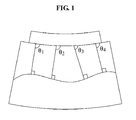
- FIG. 1 is a view illustrating an example of irradiating an ultrasonic beam to an object according to an embodiment of the present invention.
- the ultrasound system may emit an ultrasonic beam to an object, and may receive an ultrasonic echo signal reflected from the surface of the object at a right angle.
- the ultrasound system may emit an ultrasonic beam onto an object having a curved surface along the line, and may receive the ultrasonic echo signal reflected from the surface of the object at a right angle.
- the ultrasound system may calculate an emission angle between a virtual line of the ultrasonic echo signal reflected from the object and a contour line.
- the ultrasound system may calculate an emission angle between a virtual line of the received ultrasonic echo signal reflected from the object and an arc-shaped contour line of an ultrasound image.
- the ultrasound system may store, in a mapping table, reflection angles corresponding to reflections of the ultrasonic echo signal from the object.
- the ultrasound system may store, in a mapping table, reflection angles of the ultrasonic beam reflected from the object corresponding to the ultrasonic echo signal projected from each point of a probe.
- the ultrasound system may adjust the emission angle of the ultrasonic beam based on the mapping table, and may project the ultrasonic beam.
- the ultrasound system may adjust the emission angle of the ultrasonic beam by referring to the mapping table storing the reflection angles of the ultrasonic echo signal reflected from the object at a right angle, and may project the ultrasonic beam to the object.
- FIG. 2 is a block diagram illustrating an internal structure of an ultrasound system 200 according to an embodiment of the present invention.
- the ultrasound system 200 may include a probe 210, a processor 220, a mapping table 230, and a controller 240.
- the probe 210 may emit an ultrasonic beam to an object in response to an emission command of an operator using an interface.
- the probe 210 may emit an ultrasonic beam to an object, and may receive the ultrasonic beam reflected from the object.
- the probe 210 may transmit information about an emission angle and a received angle of the ultrasonic beam to the processor 220.
- the processor 220 may measure a reflection angle of the ultrasonic beam at a predetermined point in the object based on information about the emission angle and the received angle of the ultrasonic beam.
- the processor 220 may provide the mapping table 230 with information about the predetermined point where the reflection angle was measured and information about the reflection angle measured at the predetermined point.
- the mapping table 230 may map the measured reflection angle to the predetermined point and may record mapping data.
- the mapping table 230 may arrange the reflection angles of the ultrasonic beam measured for each line in a table.
- the mapping table 230 may arrange the measured reflection angles of the ultrasonic echo signal in a table.
- the controller 240 may determine an emission angle of the ultrasonic beam to the predetermined point based on the reflection angle recorded in the mapping table 230.
- the controller 240 may control the probe 210 to emit the ultrasonic beam at the determined emission angle.
- the controller 240 may calculate an emission angle between a virtual line of the ultrasonic echo signal reflected from the object at a right angle and a contour line corresponding to an arc-shaped display. The controller 240 may adjust an emission angle so that a reflection angle of the ultrasonic beam emitted to the predetermined point is a right angle.
- the ultrasound system 200 may process the ultrasonic beam received in the probe 210 as a signal to generate a high-resolution ultrasound image, and the ultrasonic beam may be optimized through adjustment of the emission angle by the controller 240.
- FIG. 3 is a flowchart illustrating a method for operating the ultrasound system 200 of FIG. 2 .
- the method for operating the ultrasound system 200 according to an embodiment of the present invention may be implemented by the ultrasound system 200 of FIG. 2 .
- the description of FIG. 3 is made with reference to FIG. 2 for ease of description.
- the ultrasound system 200 may control the probe to emit an ultrasonic beam to an object in response to an emission command of an operator using an interface.
- the ultrasound system 200 may emit an ultrasonic beam to an object through the probe, and may receive an ultrasonic echo signal reflected from the object.
- the ultrasound system 200 may obtain information about an emission angle and a received angle of the ultrasonic beam used to measure a reflection angle of the ultrasonic beam.
- the ultrasound system 200 may measure a reflection angle of the ultrasonic beam at a predetermined point in the object based on information about the emission angle and the received angle of the ultrasonic beam.
- the ultrasound system 200 may store, in the mapping table, information about the point where the reflection angle of the ultrasonic beam was measured and information about the reflection angle of the ultrasonic beam measured at the point.
- the ultrasound system 200 may map the measured reflection angle to the point and may record mapping data in the mapping table.
- the ultrasound system 200 may measure a reflection angle at a line point based on information about the emission angle of the ultrasonic beam.
- the ultrasound system 200 may arrange the reflection angles of the ultrasonic beam measured for each line in the mapping table.
- the ultrasound system 200 may measure reflection angles of the ultrasonic echo signal larger than a predetermined amount.
- the ultrasound system 200 may arrange the measured reflection angles of the ultrasonic echo signal in the mapping table.
- the ultrasound system 200 may determine an emission angle of the ultrasonic beam to the point based on the reflection angle recorded in the mapping table.
- the ultrasound system 200 may control the probe to emit the ultrasonic beam at the determined emission angle.
- the ultrasound system 200 may calculate an emission angle between a virtual line of the ultrasonic echo signal reflected from the object at a right angle and a contour line corresponding to an arc-shaped display. That is, the ultrasound system 200 may adjust an emission angle so that a reflection angle of the ultrasonic beam emitted to the point is a right angle.
- the ultrasound system 200 may perform signal processing of the ultrasonic echo signal received in the probe to generate a high-resolution ultrasound image, and the ultrasonic beam may be optimized through adjustment of the emission angle by the controller.
- non-transitory computer-readable media including program instructions to implement various operations embodied by a computer.
- the media may also include, alone or in combination with the program instructions, data files, data structures, and the like.
- Examples of non-transitory computer-readable media include magnetic media such as hard disks, floppy disks, and magnetic tape; optical media such as CD ROM disks and DVDs; magneto-optical media such as optical disks; and hardware devices that are specially configured to store and perform program instructions, such as read-only memory (ROM), random access memory (RAM), flash memory, and the like.
- Examples of program instructions include both machine code, such as produced by a compiler, and files containing higher level code that may be executed by the computer using an interpreter.
- the described hardware devices may be configured to act as one or more software modules in order to perform the operations of the above-described exemplary embodiments of the present invention, or vice versa.
Landscapes
- Engineering & Computer Science (AREA)
- Physics & Mathematics (AREA)
- Health & Medical Sciences (AREA)
- Life Sciences & Earth Sciences (AREA)
- General Physics & Mathematics (AREA)
- Remote Sensing (AREA)
- Radar, Positioning & Navigation (AREA)
- General Health & Medical Sciences (AREA)
- Pathology (AREA)
- Computer Networks & Wireless Communication (AREA)
- Medical Informatics (AREA)
- Public Health (AREA)
- Biomedical Technology (AREA)
- Surgery (AREA)
- Chemical & Material Sciences (AREA)
- Molecular Biology (AREA)
- Radiology & Medical Imaging (AREA)
- Animal Behavior & Ethology (AREA)
- Nuclear Medicine, Radiotherapy & Molecular Imaging (AREA)
- Biophysics (AREA)
- Veterinary Medicine (AREA)
- Acoustics & Sound (AREA)
- Heart & Thoracic Surgery (AREA)
- Analytical Chemistry (AREA)
- Biochemistry (AREA)
- Immunology (AREA)
- Computer Vision & Pattern Recognition (AREA)
- Signal Processing (AREA)
- Data Mining & Analysis (AREA)
- Databases & Information Systems (AREA)
- Epidemiology (AREA)
- Primary Health Care (AREA)
- Ultra Sonic Daignosis Equipment (AREA)
Abstract
Provided are an ultrasound system and a method for operating the ultrasound system, which may calculate a direction of an ultrasonic beam in real time and may adjust the ultrasonic beam based on the calculation result. The ultrasound system may include a probe to emit an ultrasonic beam to an object, a processor to measure a first reflection angle of the ultrasonic beam at a predetermined point in the object, a mapping table to map the measured first reflection angle to the predetermined point and to record mapping data, and a controller to determine an emission angle of the ultrasonic beam to the predetermined point based on the first reflection angle recorded in the mapping table, and to control the probe to emit the ultrasonic beam at the determined emission angle.
Description
- This application claims the benefit of Korean Patent Application No.
10-2010-0102649, filed on October 20, 2010 - The present invention relates to an ultrasound system and a method for operating the ultrasound system, which may calculate a direction of an ultrasonic beam in real time and may adjust the ultrasonic beam based on a result of the calculation.
- An ultrasound system is an apparatus for transmitting, from the surface of a body, an ultrasound wave signal toward a predetermined structure, that is, an object such as a fetus or an internal organ, inside the body, and for visualizing a cross section of soft tissues or a blood flow using information of an ultrasound wave echo signal reflected from the tissues of the body.
- This ultrasound system has advantages of a small size, a low cost, a real-time display, and a high stability without exposing patients and users to X-ray radiation and thus, the ultrasound system is widely used along with other diagnostic imaging systems such as an X-ray diagnosis equipment, a computerized tomography (CT) scanner, a magnetic resonance imaging (MRI) equipment, a nuclear medicine diagnosis equipment, and the like.
- The ultrasound system transmits an ultrasonic beam toward a predetermined region in the body, and obtains and outputs an image using an ultrasonic echo signal reflected from the tissues of the body. When an angle of the ultrasonic echo signal reflected from the tissues of the body is a right angle, the obtained image is clearer. Currently, however, the ultrasound system does not apply a direction of the ultrasonic beam to obtain an image.
- An aspect of the present invention provides an ultrasound system and a method for operating the ultrasound system, which may emit, to an object in a body, an ultrasonic beam using a probe, may sense an ultrasonic echo signal reflected from the object, may measure a reflection angle of the ultrasonic beam in real time, and may adjust an emission angle of the ultrasonic beam based on the reflection angle.
- Another aspect of the present invention provides an ultrasound system and a method for operating the ultrasound system, which may calculate and display an emission angle between a virtual line of an ultrasonic echo signal reflected from an object at a right angle and a contour line of an output display, thereby improving an image resolution of the object.
- Still another aspect of the present invention provides an ultrasound system and a method for operating the ultrasound system, which may emit, to an object, an ultrasonic beam for each line, may arrange reflection angles of the ultrasonic beam in a table, and may update an angle of the ultrasonic beam, thereby optimizing the ultrasonic beam emission.
- Yet another aspect of the present invention provides an ultrasound system and a method for operating the ultrasound system, which may emit, to an object, an ultrasonic beam of a predetermined intensity among various intensities, and may arrange reflection angles of an ultrasonic echo signal larger than a predetermined amount in a table, thereby improving accuracy of table values.
- According to an aspect of the present invention, there is provided an ultrasound system including a probe to emit an ultrasonic beam to an object, a processor to measure a first reflection angle of the ultrasonic beam at a predetermined point in the object, a mapping table to map the measured first reflection angle to the predetermined point and to record mapping data, and a controller to determine an emission angle of the ultrasonic beam to the predetermined point based on the first reflection angle recorded in the mapping table, and to control the probe to emit the ultrasonic beam at the determined emission angle.
- According to another aspect of the present invention, there is provided a method for operating an ultrasonic system including emitting an ultrasonic beam to an object by a probe, measuring a first reflection angle of the ultrasonic beam at a predetermined point in the object by a processor, mapping the measured first reflection angle to the predetermined point and recording mapping data by a mapping table, and determining an emission angle of the ultrasonic beam to the predetermined point based on the first reflection angle recorded in the mapping table and controlling the probe to emit the ultrasonic beam at the determined emission angle, by a controller.
- According to an aspect of the present invention, provided are an ultrasound system and a method for operating the ultrasound system, which may emit, to an object in a body, an ultrasonic beam using a probe, may sense an ultrasonic echo signal reflected from the object, may measure a reflection angle of the ultrasonic beam in real time, and may adjust an emission angle of the ultrasonic beam based on the reflection angle, thereby improving resolution of an ultrasound image.
- According to another aspect of the present invention, provided are an ultrasound system and a method for operating the ultrasound system, which may calculate and display an emission angle between a virtual line of an ultrasonic echo signal reflected from an object in a body at a right angle and a contour line of a display outputting an ultrasound image, thereby obtaining information for improving an image resolution of the object.
- According to still another aspect of the present invention, provided are an ultrasound system and a method for operating the ultrasound system, which may emit, to an object, an ultrasonic beam for each line, may arrange reflection angles of the ultrasonic beam in a table, and may update an emission angle of the ultrasonic beam to optimize the ultrasonic beam emission, thereby improving resolution of an ultrasound image.
- According to yet another aspect of the present invention, provided are an ultrasound system and a method for operating the ultrasound system, which may emit, to an object, an ultrasonic beam of a predetermined intensity among various intensities, and may arrange reflection angles of an ultrasonic echo signal larger than a predetermined amount in a table to improve accuracy of table values, thereby optimizing the ultrasonic beam emission by enhancing the accuracy of the table values.
- These and/or other aspects, features, and advantages of the invention will become apparent and more readily appreciated from the following description of exemplary embodiments, taken in conjunction with the accompanying drawings of which:
-
FIG. 1 is a view illustrating an example of irradiating an ultrasonic beam to an object according to an embodiment of the present invention; -
FIG. 2 is a block diagram illustrating an internal structure of an ultrasound system according to an embodiment of the present invention; and -
FIG. 3 is a flowchart illustrating a method for operating the ultrasound system ofFIG. 2 . - Reference will now be made in detail to exemplary embodiments of the present invention, examples of which are illustrated in the accompanying drawings, wherein like reference numerals refer to the like elements throughout. Exemplary embodiments are described below to explain the present invention by referring to the figures.
-
FIG. 1 is a view illustrating an example of irradiating an ultrasonic beam to an object according to an embodiment of the present invention. - The ultrasound system may emit an ultrasonic beam to an object, and may receive an ultrasonic echo signal reflected from the surface of the object at a right angle. The ultrasound system may emit an ultrasonic beam onto an object having a curved surface along the line, and may receive the ultrasonic echo signal reflected from the surface of the object at a right angle.
- The ultrasound system may calculate an emission angle between a virtual line of the ultrasonic echo signal reflected from the object and a contour line. The ultrasound system may calculate an emission angle between a virtual line of the received ultrasonic echo signal reflected from the object and an arc-shaped contour line of an ultrasound image.
- The ultrasound system may store, in a mapping table, reflection angles corresponding to reflections of the ultrasonic echo signal from the object. The ultrasound system may store, in a mapping table, reflection angles of the ultrasonic beam reflected from the object corresponding to the ultrasonic echo signal projected from each point of a probe.
- The ultrasound system may adjust the emission angle of the ultrasonic beam based on the mapping table, and may project the ultrasonic beam. The ultrasound system may adjust the emission angle of the ultrasonic beam by referring to the mapping table storing the reflection angles of the ultrasonic echo signal reflected from the object at a right angle, and may project the ultrasonic beam to the object.
-
FIG. 2 is a block diagram illustrating an internal structure of anultrasound system 200 according to an embodiment of the present invention. - The
ultrasound system 200 according to an embodiment of the present invention may include aprobe 210, aprocessor 220, a mapping table 230, and acontroller 240. - The
probe 210 may emit an ultrasonic beam to an object in response to an emission command of an operator using an interface. Theprobe 210 may emit an ultrasonic beam to an object, and may receive the ultrasonic beam reflected from the object. Theprobe 210 may transmit information about an emission angle and a received angle of the ultrasonic beam to theprocessor 220. - The
processor 220 may measure a reflection angle of the ultrasonic beam at a predetermined point in the object based on information about the emission angle and the received angle of the ultrasonic beam. Theprocessor 220 may provide the mapping table 230 with information about the predetermined point where the reflection angle was measured and information about the reflection angle measured at the predetermined point. - The mapping table 230 may map the measured reflection angle to the predetermined point and may record mapping data. When the
probe 210 emits the ultrasonic beam to the object for each line and theprocessor 220 measures a reflection angle at a line point based on information about the emission angle of the ultrasonic beam, the mapping table 230 may arrange the reflection angles of the ultrasonic beam measured for each line in a table. - Also, when the
probe 210 emits a predetermined intensity of the ultrasonic beam onto the object and theprocessor 220 measures reflection angles of the ultrasonic echo signal larger than a predetermined amount, the mapping table 230 may arrange the measured reflection angles of the ultrasonic echo signal in a table. - The
controller 240 may determine an emission angle of the ultrasonic beam to the predetermined point based on the reflection angle recorded in the mapping table 230. Thecontroller 240 may control theprobe 210 to emit the ultrasonic beam at the determined emission angle. - The
controller 240 may calculate an emission angle between a virtual line of the ultrasonic echo signal reflected from the object at a right angle and a contour line corresponding to an arc-shaped display. Thecontroller 240 may adjust an emission angle so that a reflection angle of the ultrasonic beam emitted to the predetermined point is a right angle. - The
ultrasound system 200 may process the ultrasonic beam received in theprobe 210 as a signal to generate a high-resolution ultrasound image, and the ultrasonic beam may be optimized through adjustment of the emission angle by thecontroller 240. -
FIG. 3 is a flowchart illustrating a method for operating theultrasound system 200 ofFIG. 2 . - The method for operating the
ultrasound system 200 according to an embodiment of the present invention may be implemented by theultrasound system 200 ofFIG. 2 . Hereinafter, the description ofFIG. 3 is made with reference toFIG. 2 for ease of description. - In
operation 310, theultrasound system 200 may control the probe to emit an ultrasonic beam to an object in response to an emission command of an operator using an interface. Theultrasound system 200 may emit an ultrasonic beam to an object through the probe, and may receive an ultrasonic echo signal reflected from the object. Theultrasound system 200 may obtain information about an emission angle and a received angle of the ultrasonic beam used to measure a reflection angle of the ultrasonic beam. - In
operation 320, theultrasound system 200 may measure a reflection angle of the ultrasonic beam at a predetermined point in the object based on information about the emission angle and the received angle of the ultrasonic beam. Theultrasound system 200 may store, in the mapping table, information about the point where the reflection angle of the ultrasonic beam was measured and information about the reflection angle of the ultrasonic beam measured at the point. - In
operation 330, theultrasound system 200 may map the measured reflection angle to the point and may record mapping data in the mapping table. When theultrasound system 200 emits the ultrasonic beam to the object for each line through the probe, theultrasound system 200 may measure a reflection angle at a line point based on information about the emission angle of the ultrasonic beam. Theultrasound system 200 may arrange the reflection angles of the ultrasonic beam measured for each line in the mapping table. - Also, when the
ultrasound system 200 emits a predetermined intensity of an ultrasonic beam to the object through the probe, theultrasound system 200 may measure reflection angles of the ultrasonic echo signal larger than a predetermined amount. Theultrasound system 200 may arrange the measured reflection angles of the ultrasonic echo signal in the mapping table. - In
operation 340, theultrasound system 200 may determine an emission angle of the ultrasonic beam to the point based on the reflection angle recorded in the mapping table. Theultrasound system 200 may control the probe to emit the ultrasonic beam at the determined emission angle. - The
ultrasound system 200 may calculate an emission angle between a virtual line of the ultrasonic echo signal reflected from the object at a right angle and a contour line corresponding to an arc-shaped display. That is, theultrasound system 200 may adjust an emission angle so that a reflection angle of the ultrasonic beam emitted to the point is a right angle. - In
operation 350, theultrasound system 200 may perform signal processing of the ultrasonic echo signal received in the probe to generate a high-resolution ultrasound image, and the ultrasonic beam may be optimized through adjustment of the emission angle by the controller. - The above-described exemplary embodiments of the present invention may be recorded in non-transitory computer-readable media including program instructions to implement various operations embodied by a computer. The media may also include, alone or in combination with the program instructions, data files, data structures, and the like. Examples of non-transitory computer-readable media include magnetic media such as hard disks, floppy disks, and magnetic tape; optical media such as CD ROM disks and DVDs; magneto-optical media such as optical disks; and hardware devices that are specially configured to store and perform program instructions, such as read-only memory (ROM), random access memory (RAM), flash memory, and the like. Examples of program instructions include both machine code, such as produced by a compiler, and files containing higher level code that may be executed by the computer using an interpreter. The described hardware devices may be configured to act as one or more software modules in order to perform the operations of the above-described exemplary embodiments of the present invention, or vice versa.
- Although a few exemplary embodiments of the present invention have been shown and described, the present invention is not limited to the described exemplary embodiments. Instead, it would be appreciated by those skilled in the art that changes may be made to these exemplary embodiments without departing from the principles and spirit of the invention, the scope of which is defined by the claims and their equivalents.
Claims (12)
- An ultrasound system for adjusting an ultrasonic beam direction, the system comprising:a probe to emit an ultrasonic beam to an object;a processor to measure a first reflection angle of the ultrasonic beam at a predetermined point in the object;a mapping table to map the measured first reflection angle to the predetermined point
and to record mapping data; anda controller to determine an emission angle of the ultrasonic beam to the predetermined point based on the first reflection angle recorded in the mapping table, and to control the probe to emit the ultrasonic beam at the determined emission angle. - The system of claim 1, wherein the controller adjusts the emission angle by the controller so that a second reflection angle of the ultrasonic beam emitted to the predetermined point is a right angle.
- The system of claim 2, wherein the mapping table updates and records the first reflection angle based on the adjusted emission angle.
- The system of claim 1, wherein the controller calculates the emission angle between a virtual line of the ultrasonic beam reflected from the object at a right angle and a contour line, the emission angle having the same angle as the ultrasonic beam outputted from the probe.
- The system of claim 1, wherein the probe emits the ultrasonic beam to the object for each line, and
the mapping table arranges the first reflection angles of an ultrasonic echo signal measured for each line in a table. - The system of claim 5, wherein the probe emits the object with a predetermined intensity of an ultrasonic beam, and
the mapping table arranges the first reflection angles of the ultrasonic echo signal larger than a predetermined amount in a table. - A method for operating an ultrasonic system for adjusting an ultrasonic beam direction, the method comprising:emitting an ultrasonic beam to an object by a probe;measuring a first reflection angle of the ultrasonic beam at a predetermined point in the object by a processor;mapping the measured first reflection angle to the predetermined point, and recording mapping data, by a mapping table; anddetermining an emission angle of the ultrasonic beam to the predetermined point based on the first reflection angle recorded in the mapping table, and controlling the probe to emit the ultrasonic beam at the determined emission angle, by a controller.
- The method of claim 7, further comprising:adjusting, by the controller, the emission angle by the control so that a second reflection angle of the ultrasonic beam emitted to the predetermined point is a right angle.
- The method of claim 8, further comprising:updating and recording the first reflection angle based on the adjusted emission angle by the mapping table.
- The method of claim 7, further comprising:calculating the emission angle between a virtual line of an ultrasonic echo signal reflected from the object at a right angle and a contour line by the controller, the emission angle having the same angle as the ultrasonic beam outputted from the probe.
- The method of claim 7, further comprising:emitting the ultrasonic beam to the object for each line by the probe; andarranging the first reflection angles of an ultrasonic echo signal measured for each line in a table by the mapping table.
- The method of claim 11, further comprising:emitting a predetermined intensity of an ultrasonic beam to the object, by the probe; andarranging the first reflection angles of the ultrasonic beam larger than a predetermined amount in a table, by the mapping table.
Applications Claiming Priority (1)
| Application Number | Priority Date | Filing Date | Title |
|---|---|---|---|
| KR1020100102649A KR101194280B1 (en) | 2010-10-20 | 2010-10-20 | Ultrasound system for adjusting derection of ultrasound beam according to ultrasound beam and method for operating ultrasound system |
Publications (1)
| Publication Number | Publication Date |
|---|---|
| EP2444000A1 true EP2444000A1 (en) | 2012-04-25 |
Family
ID=45346180
Family Applications (1)
| Application Number | Title | Priority Date | Filing Date |
|---|---|---|---|
| EP11163082A Withdrawn EP2444000A1 (en) | 2010-10-20 | 2011-04-19 | Ultrasound System for Adjusting Ultrasonic Beam Direction and Method for Operating Ultrasound System |
Country Status (4)
| Country | Link |
|---|---|
| US (1) | US20120101382A1 (en) |
| EP (1) | EP2444000A1 (en) |
| JP (1) | JP2012086016A (en) |
| KR (1) | KR101194280B1 (en) |
Cited By (1)
| Publication number | Priority date | Publication date | Assignee | Title |
|---|---|---|---|---|
| CN103211613A (en) * | 2012-11-09 | 2013-07-24 | 深圳市恩普电子技术有限公司 | Digital ultrasonic imaging display method, B ultrasound equipment and system |
Families Citing this family (1)
| Publication number | Priority date | Publication date | Assignee | Title |
|---|---|---|---|---|
| CN108132305A (en) * | 2017-12-21 | 2018-06-08 | 飞依诺科技(苏州)有限公司 | A kind of method and apparatus of transducer array element performance test |
Citations (4)
| Publication number | Priority date | Publication date | Assignee | Title |
|---|---|---|---|---|
| US5197475A (en) * | 1988-08-10 | 1993-03-30 | The Board Of Regents, The University Of Texas System | Method and apparatus for analyzing material properties using ultrasound |
| EP1411370A1 (en) * | 2002-10-15 | 2004-04-21 | Matsushita Electric Industrial Co., Ltd. | Image processing apparatus, method and program |
| EP1439402A1 (en) * | 2003-01-16 | 2004-07-21 | Matsushita Electric Industrial Co., Ltd. | Ultrasonic diagnostic apparatus and ultrasonic diagnostic method |
| EP1890282A2 (en) * | 2006-08-18 | 2008-02-20 | Medison Co., Ltd. | Ultrasound system and method for controlling steering angles of scan lines |
Family Cites Families (2)
| Publication number | Priority date | Publication date | Assignee | Title |
|---|---|---|---|---|
| EP1465530B1 (en) * | 2002-01-07 | 2007-05-23 | GE Medical Systems Israel Ltd. | A system and method of mapping irregularities of hard tissue |
| KR100978479B1 (en) * | 2008-11-03 | 2010-08-30 | 주식회사 메디슨 | Ultrasound system and method for performing scan conversion at high speed |
-
2010
- 2010-10-20 KR KR1020100102649A patent/KR101194280B1/en not_active Expired - Fee Related
-
2011
- 2011-04-19 EP EP11163082A patent/EP2444000A1/en not_active Withdrawn
- 2011-04-22 US US13/092,392 patent/US20120101382A1/en not_active Abandoned
- 2011-10-12 JP JP2011225267A patent/JP2012086016A/en active Pending
Patent Citations (4)
| Publication number | Priority date | Publication date | Assignee | Title |
|---|---|---|---|---|
| US5197475A (en) * | 1988-08-10 | 1993-03-30 | The Board Of Regents, The University Of Texas System | Method and apparatus for analyzing material properties using ultrasound |
| EP1411370A1 (en) * | 2002-10-15 | 2004-04-21 | Matsushita Electric Industrial Co., Ltd. | Image processing apparatus, method and program |
| EP1439402A1 (en) * | 2003-01-16 | 2004-07-21 | Matsushita Electric Industrial Co., Ltd. | Ultrasonic diagnostic apparatus and ultrasonic diagnostic method |
| EP1890282A2 (en) * | 2006-08-18 | 2008-02-20 | Medison Co., Ltd. | Ultrasound system and method for controlling steering angles of scan lines |
Cited By (1)
| Publication number | Priority date | Publication date | Assignee | Title |
|---|---|---|---|---|
| CN103211613A (en) * | 2012-11-09 | 2013-07-24 | 深圳市恩普电子技术有限公司 | Digital ultrasonic imaging display method, B ultrasound equipment and system |
Also Published As
| Publication number | Publication date |
|---|---|
| KR101194280B1 (en) | 2012-10-24 |
| US20120101382A1 (en) | 2012-04-26 |
| KR20120041064A (en) | 2012-04-30 |
| JP2012086016A (en) | 2012-05-10 |
Similar Documents
| Publication | Publication Date | Title |
|---|---|---|
| JP2023519876A (en) | Systems and methods for identifying regions of interest in multiple imaging modalities | |
| US20080275339A1 (en) | Determination of sound propagation speed in navigated surgeries | |
| US11864950B2 (en) | Image guided steering of a transducer array and/or an instrument | |
| US20120154400A1 (en) | Method of reducing noise in a volume-rendered image | |
| US11937887B2 (en) | Ultrasound system and method for tracking movement of an object | |
| US20160225180A1 (en) | Measurement tools with plane projection in rendered ultrasound volume imaging | |
| US20140330121A1 (en) | Ultrasonic imaging apparatus and control method thereof | |
| JP7846418B2 (en) | Fetal heart rate monitoring | |
| JP2020500084A (en) | Ultrasound system for enhanced instrument visualization | |
| KR102406937B1 (en) | Ultrasound imaging apparatus and controlling method of the same | |
| JP5566841B2 (en) | Image processing apparatus and program | |
| US20150105658A1 (en) | Ultrasonic imaging apparatus and control method thereof | |
| KR101219465B1 (en) | Method and apparatus for correcting ultrasound images using a map of interest index | |
| US20170281135A1 (en) | Image Registration Fiducials | |
| US20120101382A1 (en) | Ultrasound system for adjusting ultrasonic beam direction and method for operating ultrasound system | |
| KR101194285B1 (en) | 3d ultrasound system for provide beam direction and method for operating 3d ultrasound system | |
| US20080170657A1 (en) | Methods and Apparatus for Range Based X-Ray Attenuation | |
| US20190388061A1 (en) | Ultrasound diagnosis apparatus displaying shear wave data for object and method for operating same | |
| US20170046848A1 (en) | Workstation, medical imaging apparatus including the same, and control method for the same | |
| US20250302430A1 (en) | Tracking system for 3d transcranial tracking of a medical device | |
| EP2433568A1 (en) | Ultrasound system for combining images of various angles and method for operating ultrasound system | |
| US12542206B2 (en) | Medical support device, medical image capturing system, medical support method, and program | |
| US20240341734A1 (en) | Ultrasound Depth Calibration for Improving Navigational Accuracy | |
| CN120859553A (en) | Determination of enhanced quantitative ultrasound medical imaging by interventional tissue | |
| JP2018134122A (en) | Body tissue position measurement device |
Legal Events
| Date | Code | Title | Description |
|---|---|---|---|
| AK | Designated contracting states |
Kind code of ref document: A1 Designated state(s): AL AT BE BG CH CY CZ DE DK EE ES FI FR GB GR HR HU IE IS IT LI LT LU LV MC MK MT NL NO PL PT RO RS SE SI SK SM TR |
|
| AX | Request for extension of the european patent |
Extension state: BA ME |
|
| PUAI | Public reference made under article 153(3) epc to a published international application that has entered the european phase |
Free format text: ORIGINAL CODE: 0009012 |
|
| 17P | Request for examination filed |
Effective date: 20120928 |
|
| STAA | Information on the status of an ep patent application or granted ep patent |
Free format text: STATUS: THE APPLICATION IS DEEMED TO BE WITHDRAWN |
|
| 18D | Application deemed to be withdrawn |
Effective date: 20151103 |