EP2443431B1 - Particle collection device - Google Patents
Particle collection device Download PDFInfo
- Publication number
- EP2443431B1 EP2443431B1 EP10731865.1A EP10731865A EP2443431B1 EP 2443431 B1 EP2443431 B1 EP 2443431B1 EP 10731865 A EP10731865 A EP 10731865A EP 2443431 B1 EP2443431 B1 EP 2443431B1
- Authority
- EP
- European Patent Office
- Prior art keywords
- body portion
- mesh
- clamping bar
- preconcentrator
- cartridge assembly
- Prior art date
- Legal status (The legal status is an assumption and is not a legal conclusion. Google has not performed a legal analysis and makes no representation as to the accuracy of the status listed.)
- Active
Links
Images


Classifications
-
- B—PERFORMING OPERATIONS; TRANSPORTING
- B01—PHYSICAL OR CHEMICAL PROCESSES OR APPARATUS IN GENERAL
- B01D—SEPARATION
- B01D46/00—Filters or filtering processes specially modified for separating dispersed particles from gases or vapours
- B01D46/10—Particle separators, e.g. dust precipitators, using filter plates, sheets or pads having plane surfaces
-
- B—PERFORMING OPERATIONS; TRANSPORTING
- B01—PHYSICAL OR CHEMICAL PROCESSES OR APPARATUS IN GENERAL
- B01D—SEPARATION
- B01D46/00—Filters or filtering processes specially modified for separating dispersed particles from gases or vapours
- B01D46/0002—Casings; Housings; Frame constructions
- B01D46/0005—Mounting of filtering elements within casings, housings or frames
-
- B—PERFORMING OPERATIONS; TRANSPORTING
- B01—PHYSICAL OR CHEMICAL PROCESSES OR APPARATUS IN GENERAL
- B01D—SEPARATION
- B01D46/00—Filters or filtering processes specially modified for separating dispersed particles from gases or vapours
- B01D46/66—Regeneration of the filtering material or filter elements inside the filter
- B01D46/80—Chemical processes for the removal of the retained particles, e.g. by burning
- B01D46/84—Chemical processes for the removal of the retained particles, e.g. by burning by heating only
-
- G—PHYSICS
- G01—MEASURING; TESTING
- G01N—INVESTIGATING OR ANALYSING MATERIALS BY DETERMINING THEIR CHEMICAL OR PHYSICAL PROPERTIES
- G01N1/00—Sampling; Preparing specimens for investigation
- G01N1/02—Devices for withdrawing samples
- G01N1/22—Devices for withdrawing samples in the gaseous state
- G01N1/2202—Devices for withdrawing samples in the gaseous state involving separation of sample components during sampling
- G01N1/2214—Devices for withdrawing samples in the gaseous state involving separation of sample components during sampling by sorption
-
- G—PHYSICS
- G01—MEASURING; TESTING
- G01N—INVESTIGATING OR ANALYSING MATERIALS BY DETERMINING THEIR CHEMICAL OR PHYSICAL PROPERTIES
- G01N1/00—Sampling; Preparing specimens for investigation
- G01N1/28—Preparing specimens for investigation including physical details of (bio-)chemical methods covered elsewhere, e.g. G01N33/50, C12Q
- G01N1/40—Concentrating samples
- G01N1/405—Concentrating samples by adsorption or absorption
-
- G—PHYSICS
- G01—MEASURING; TESTING
- G01N—INVESTIGATING OR ANALYSING MATERIALS BY DETERMINING THEIR CHEMICAL OR PHYSICAL PROPERTIES
- G01N1/00—Sampling; Preparing specimens for investigation
- G01N1/02—Devices for withdrawing samples
- G01N2001/022—Devices for withdrawing samples sampling for security purposes, e.g. contraband, warfare agents
-
- H—ELECTRICITY
- H02—GENERATION; CONVERSION OR DISTRIBUTION OF ELECTRIC POWER
- H02G—INSTALLATION OF ELECTRIC CABLES OR LINES, OR OF COMBINED OPTICAL AND ELECTRIC CABLES OR LINES
- H02G5/00—Installations of bus-bars
Definitions
- the present disclosure relates generally to the field of particle collection devices, and more specifically, to particle collection and similar devices used to screen objects.
- the flow of the main gas stream is then interrupted by diaphragm shutter valves, whereupon a cross-flow of carrier gas stream is blown parallel past the faces of the screen to dislodge the accumulated particles and carry them to a particle or vapor detector, such as an ion mobility spectrometer.
- a particle or vapor detector such as an ion mobility spectrometer.
- the mesh of such embodiment may comprise a stainless steel mesh.
- the cartridge assembly may further comprise a clamping assembly for securing one or more of the scalloped surface or the bus bar into contact with a mesh disposed between the scalloped surface and the bus bar.
- the cartridge assembly may further comprise another body portion to which the clamping bar is mounted, wherein at least one of the body portion or the other body portion has a concave profile.
- the body portion and the other body portion may be coupled by a hinge.
- Yet another embodiment relates to a screening device comprising a source configured to generate a flow of air through which an object is to pass; and a preconcentrator according to claim 5, disposed in a path of the flow, the preconcentrator being configured to capture particulate matter dislodged from the object by the flow.
- a particle collection device 10 (e.g., a cartridge assembly, a mesh cartridge assembly, a preconcentrator, etc.) is shown according to an exemplary embodiment.
- Particle collection device 10 includes a body 12 having a first portion or housing 14 (e.g., a body portion, a first body portion, a housing, etc.) and a second portion or door 16 (e.g., an other body portion, a second body portion, a door or door assembly, etc.).
- One or more disconnect members 13 may be provided to provide electrical connectivity between particle collection device 10 and other components.
- Device 10 may include a handle 15 configured to facilitate the insertion and/or removal of device 10 from another component, such as a screening device, etc.
- device 10 may be a preconcentrator that is used to capture particles, such as particles of narcotics and/or explosive materials, blown off a human passing through a security screening device.
- device 10 is configured to be placed in the path of an airflow and capture particles travelling within the airflow.
- the particle collection device can be used in any suitable instrument or configuration, such as, for example, in walk-through detection equipment (e.g. portals) at security or customs checkpoints.
- device 10 may utilized as part of a screening device (e.g., a portal, etc.) such that air is directed along an air flow 37 from an air source 34 over and/or past an object (e.g., a person, luggage, etc.) and passes through device 10.
- Device 10 captures particles travelling with the air passing along air flow 37 through device 10.
- device 10 may further comprise a mesh 26 (e.g., a stainless-steel mesh material or assembly, a filter, screen, wire mesh, etc.).
- Mesh 26 may be placed in the path of the airflow travelling through device 10 and be configured to collect particles with traces of target compounds, including but not limited to, narcotic or explosive substances.
- mesh 26 is sized to capture particles of the size of narcotic or explosive particles expected to cling to objects. After the collection of particles is accomplished, heat can be applied to mesh 26 to release, e.g., liberate, captured particles, and the resulting vapors can be analyzed using any suitable method, such as, for example ion mobility spectrometry (IMS).
- IMS ion mobility spectrometry
- mesh 26 may be generally square in shape. According to various other embodiments, mesh 26 may be any suitable type and take any suitable shape (e.g., a shape suitable to cover apertures 28, 36, circular, rectangular, etc.).
- the mesh material may be electrically and/or thermally conductive to facilitate heating of mesh 26, e.g., act as a resistor). For example, a stainless steel mesh is used to capture particles blown off a human at least partially positioned in the air flow.
- mesh 26 may be a removeable/replaceable component of device 10.
- Door 16 may further include one or more clamping bars 20 (e.g., clamping members, bus bars, etc.).
- clamping bars 20 and bus bars 18 generally face one another when door 16 is closed such that mesh 26 is secured between clamping bars 20 and bus bars 18.
- Clamping bars 20 and bus bars 18 are in electrical and/or thermal contact with mesh 26.
- One or more of bus bars 18 and/or clamping bars 20 are biased toward the other (e.g., via a spring, a curvature in the component profile, etc.) to further increase the retention force on mesh 26.
- the relative positions of bus bars 18 and clamping bars 20 may be reversed in some embodiments.
- the transition between the portion of mesh 26 sandwiched between bus bars 18 and clamping bars 20 and the unsupported portion of mesh 26 can occur along a line 27 that follows a machined scalloped profile of clamping bars 20, thus increasing the length of transition line 27 (relative to a generally straight transition line).
- transition line 27 can be more than two times longer than a straight transition line on the same clamping bar.
- Scallops 23 provide depth to the transition phenomenon that is defined by the distance from the crest of each scallop 23 to a front edge or surface 29 of each clamping bar 20. The ends of the scalloped notches 23 can be increased to decrease the amount of contact between the edge of mesh 26 and clamping bars 20 and/or bus bars 18.
- Deeper ended scalloped notches also reduce contact of mesh 26 with bus bars 18, m tum minimizing heat or electronic damage that may otherwise may occur to mesh 26.
- overheating of mesh 26 e.g., a stainless steel mesh
- clamping bar 20 may have intermittent (e.g., noncontinuous, etc.) electrical contact with mesh 26.
- Device 10 may include one or more clamping assemblies, shown in FIG. 2 as clamping knobs 40 (e.g., clamps, fasteners, etc.).
- Clamping knobs 40 can provide additional support for mesh 26 as it resists an airflow, including intermittent airflow that can permeate the mesh material.
- Clamping knobs 40 may be configured to secure surface 22 of clamping bar 20 and/or a surface of bus bar 18 into contact with mesh 26 disposed between clamping bars 20 and bus bars 18.
- Clamping knobs 40 can be made of any suitable material.
- device 10 further includes one or more deflection limiters, shown in FIG. 2 as support disks 35.
- Support disks 35 provide additional support for mesh 26 as the support disk may resist airflow and limit deflection of the mesh 26 due to pressure from the airflow 37 and/or from thermal expansion of the mesh 26 during heating, particularly near the clamping edge, where the mesh may be vulnerable to damage.
- Support disks 35 can be attached to either or both the housing 14 and the door 16 and can be of various shape, though in the illustrated embodiment they are round.
- the support disks 35 are formed of an electrically non-conducting material, but may be of either a thermally conducting or thermally non-conducting material.
- clamping bar 20 is shown in greater detail according to an exemplary embodiment.
- clamping bar 20 includes scallops 23 (e.g., notches, recesses, grooves, indents, etc.). Respective scallops may have a generally curved profile extending along a surface 22 of clamping bar 20.
- scallops 23 are formed by a cylindrical machining tool (not shown) such that the tool rotates and forms the curved surface of the scallop.
- the size, shape, and depth of the scallops can be controlled by adjusting the depth of cut and/or angle of the tool.
- one or more generally cylindrically-shaped recesses 42 are provided in a bottom surface of clamping bar 20.
Landscapes
- Chemical & Material Sciences (AREA)
- Chemical Kinetics & Catalysis (AREA)
- Health & Medical Sciences (AREA)
- Life Sciences & Earth Sciences (AREA)
- Analytical Chemistry (AREA)
- General Physics & Mathematics (AREA)
- Molecular Biology (AREA)
- Physics & Mathematics (AREA)
- Engineering & Computer Science (AREA)
- Biochemistry (AREA)
- General Health & Medical Sciences (AREA)
- Biomedical Technology (AREA)
- Immunology (AREA)
- Pathology (AREA)
- Electrostatic Separation (AREA)
- Treatment Of Fiber Materials (AREA)
- Filtering Materials (AREA)
- Sampling And Sample Adjustment (AREA)
Description
- The present disclosure relates generally to the field of particle collection devices, and more specifically, to particle collection and similar devices used to screen objects.
- Screening for explosive materials and illegal narcotics is now routine in airports, train stations, sports arenas, and other locations charged with handling large volumes of individuals. Often, individuals and their belongings must be screened for explosive materials and/or explosive residues. While it is desirable to identify individuals carrying illegal narcotics, it is also important from a security standpoint, to screen individuals for the presence of explosive materials.
-
US 6,978,657 , on which the preamble of claim 1 is based, describes a portable system for the detection of chemical particles such as explosive residue which utilizes a metal fiber substrate that may either be swiped over a subject or placed in a holder in a collection module which can shoot a jet of gas at the subject to dislodge residue, and then draw the air containing the residue into the substrate. The holder is then placed in a detection module, which resistively heats the substrate to evolve the particles, and provides a gas flow to move the particles to a miniature detector in the module.
US 7,299,711 B1 discloses a method and system for controllably releasing contaminants from a contaminated porous metallic mesh by thermally desorbing and releasing a selected subset of contaminants from a contaminated mesh by rapidly raising the mesh to a pre-determined temperature step or plateau that has been chosen beforehand to preferentially desorb a particular chemical specie of interest, but not others.
US 5,854,431 A discloses an apparatus and method for preconcentrating particles and vapors. The preconcentrator apparatus permits detection of highly diluted amounts of particles in a main gas stream, such as a stream of ambient air. A main gas stream having airborne particles entrained therein is passed through a pervious screen. The particles accumulate upon the screen, as the screen acts as a sort of selective particle filter. The flow of the main gas stream is then interrupted by diaphragm shutter valves, whereupon a cross-flow of carrier gas stream is blown parallel past the faces of the screen to dislodge the accumulated particles and carry them to a particle or vapor detector, such as an ion mobility spectrometer.
EP0905501A2 discloses a portable detection and screening system for the detection of target vapors and/or target particulates that may include explosives, chemical agents, drugs or narcotics, comprising: sampling means for gathering a sample volume of air from a specific area on an individual or object that may contain vapor or particulate emissions of said target materials, said sampling means performing said gathering in a first sampling period, means for concentrating said target vapors or vapors emanating from said target particulates contained in said sample volume of air, said means including means for collecting said target vapors or particulate emissions at a first location; means for transporting said collected target vapors or particulate emissions to a second location distinct from said first location; means for desorbing said target vapors or particulate emissions at said second location in a second sampling period; and, detection means responsive to said target vapors or particulate emissions desorbed at said second location to generate a signal in response to the presence of said target materials in said sample volume, wherein said sampling means is adapted for collecting a new sample volume of air containing target vapors or particulate emissions at said first location during said second sampling period. - One embodiment relates to a cartridge assembly according to claim 1. The mesh of such embodiment may comprise a stainless steel mesh. The cartridge assembly may further comprise a clamping assembly for securing one or more of the scalloped surface or the bus bar into contact with a mesh disposed between the scalloped surface and the bus bar. The cartridge assembly may further comprise another body portion to which the clamping bar is mounted, wherein at least one of the body portion or the other body portion has a concave profile. Here, the body portion and the other body portion may be coupled by a hinge.
- Another embodiment relates to a preconcentrator comprising a cartridge assembly according to claim 1, wherein the body portion is configured to be disposed in an airflow, the body portion defining the opening through which at least a portion of the airflow is directed; the preconcentrator comprises an other body portion defining an opening that is configured to align with the opening in the body portion when the other body portion is secured to the body portion; the clamping bar is mounted to at least one of the body portion or the other body portion, the scalloped surface of the clamping bar is configured to at least partially secure the mesh between the body portion and the other body portion, the preconcentrator comprises means for securing the body portion and the other body portion one to another.
- Yet another embodiment relates to a screening device comprising a source configured to generate a flow of air through which an object is to pass; and a preconcentrator according to claim 5, disposed in a path of the flow, the preconcentrator being configured to capture particulate matter dislodged from the object by the flow.
-
-
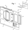
FIG. 1 illustrates a particle collection device according to an exemplary embodiment. -
FIG. 2 illustrates the particle collection device ofFIG. 1 in an open configuration according to an exemplary embodiment. -
FIG. 3A is top view of a clamping bar according to an exemplary embodiment. -
FIG. 3B is a front view of the clamping bar ofFIG. 3A according to an exemplary embodiment. -
FIG. 3C is a bottom view of the clamping bar ofFIG. 3A according to an exemplary embodiment. -
FIG. 3D is a side view of the clamping bar ofFIG. 3A taken along line C-C according to an exemplary embodiment. -
FIG. 3E is a cross-sectional view of the clamping bar ofFIG. 3A taken along line B-B according to an exemplary embodiment. -
FIG. 3F is a cross-sectional view of the clamping bar ofFIG. 3A taken along line A-A according to an exemplary embodiment. -
FIG. 3G is a perspective view of the clamping bar ofFIG. 3A according to an exemplary embodiment. - Referring to
FIG. 1 , a particle collection device 10 (e.g., a cartridge assembly, a mesh cartridge assembly, a preconcentrator, etc.) is shown according to an exemplary embodiment.Particle collection device 10 includes abody 12 having a first portion or housing 14 (e.g., a body portion, a first body portion, a housing, etc.) and a second portion or door 16 (e.g., an other body portion, a second body portion, a door or door assembly, etc.). One or moredisconnect members 13 may be provided to provide electrical connectivity betweenparticle collection device 10 and other components.Device 10 may include ahandle 15 configured to facilitate the insertion and/or removal ofdevice 10 from another component, such as a screening device, etc. For example,device 10 may be a preconcentrator that is used to capture particles, such as particles of narcotics and/or explosive materials, blown off a human passing through a security screening device. - According to embodiments,
device 10 is configured to be placed in the path of an airflow and capture particles travelling within the airflow. The particle collection device can be used in any suitable instrument or configuration, such as, for example, in walk-through detection equipment (e.g. portals) at security or customs checkpoints. For example,device 10 may utilized as part of a screening device (e.g., a portal, etc.) such that air is directed along anair flow 37 from anair source 34 over and/or past an object (e.g., a person, luggage, etc.) and passes throughdevice 10.Device 10 captures particles travelling with the air passing alongair flow 37 throughdevice 10. Upon being captured bydevice 10, the particles may be subjected to further analysis (e.g., analysis by a device such as an ion mobility spectrometry (IMS) device, a Fourier transform infrared spectroscopy (FTIR) device, and the like). - Referring to
FIG. 2 ,device 10 is shown in greater detail in accordance with various embodiments. As shown inFIG. 2 ,housing 14 anddoor 16 may be pivotally coupled to one another. For example, one ormore hinges 30 may be utilized to couplehousing 14 anddoor 16. Alternatively,housing 14 anddoor 16 may be pivotally coupled without the use of a hinge (e.g., by using one or more "pseudo-hinge" features, pivot rods, or components). According to yet another embodiment,housing 14 anddoor 16 may be completely separable and may be coupled utilizing a snap fit, interference fit, or other type of mechanical or other coupling method. - Referring further to
FIG. 2 ,housing 14 defines anaperture 28 that permits air to flow throughdevice 10. According to an embodiment,housing 14 is a generally planar member, while in other embodiments housing 14 may have a curved (e.g., concave, convex, etc.) profile with an apex extending toward or away fromdoor 16. Althoughaperture 28 is shown as being generally circular in shape, any suitable shape or configuration (e.g., square, rectangular, etc.) may be used in connection withaperture 28. One or more bus bars 18 (electrically and/or thermally conductive members, etc.) may be coupled or otherwise supported byhousing 14. In other embodiments, onebus bar 18 is provided to each of two opposite portions ofaperture 28. While bus bars 18 are shown as being generally straight, elongated members, other configurations (e.g., curved, irregularly-shaped, etc.) of bus bars may be used, and more or less bus bars than those shown inFIG. 2 may be utilized. -
Door 16 defines anaperture 36 that permits air passing throughaperture 28 to completely pass throughdevice 10. In one embodiment,apertures device 10 is in a closed or secured position (as shown inFIG. 1 ). As shown inFIG. 2 ,aperture 36 may have a generally rectangular shape, while inother embodiments aperture 36 may take other shapes and/or configurations (e.g., circular, square, etc.). Both ofapertures device 10. According to one embodiment,door 16 may have a curved (e.g., concave, convex, etc.) profile having an apex extending either toward or away fromhousing 14. One or both ofhousing 14 anddoor 16 may include one ormore supports 32 configured to provide additional support to the components ofdevice 10. - In embodiments,
device 10 may further comprise a mesh 26 (e.g., a stainless-steel mesh material or assembly, a filter, screen, wire mesh, etc.).Mesh 26 may be placed in the path of the airflow travelling throughdevice 10 and be configured to collect particles with traces of target compounds, including but not limited to, narcotic or explosive substances. For example,mesh 26 is sized to capture particles of the size of narcotic or explosive particles expected to cling to objects. After the collection of particles is accomplished, heat can be applied to mesh 26 to release, e.g., liberate, captured particles, and the resulting vapors can be analyzed using any suitable method, such as, for example ion mobility spectrometry (IMS). As shown inFIG. 2 , mesh 26 may be generally square in shape. According to various other embodiments,mesh 26 may be any suitable type and take any suitable shape (e.g., a shape suitable to coverapertures mesh 26, e.g., act as a resistor). For example, a stainless steel mesh is used to capture particles blown off a human at least partially positioned in the air flow. Furthermore, mesh 26 may be a removeable/replaceable component ofdevice 10. -
Door 16 may further include one or more clamping bars 20 (e.g., clamping members, bus bars, etc.). In one embodiment, clamping bars 20 andbus bars 18 generally face one another whendoor 16 is closed such thatmesh 26 is secured between clampingbars 20 and bus bars 18. Clamping bars 20 andbus bars 18 are in electrical and/or thermal contact withmesh 26. One or more ofbus bars 18 and/or clampingbars 20 are biased toward the other (e.g., via a spring, a curvature in the component profile, etc.) to further increase the retention force onmesh 26. Furthermore, the relative positions ofbus bars 18 and clampingbars 20 may be reversed in some embodiments. In some embodiments, bus bars 18 and clampingbars 20 are configured to retainmesh 26 so all, or at least a portion of,mesh 26 remains substantially planar as air passes throughmesh 26. In additional embodiments, an insert 38 (e.g., a thermal insert, an electrically and/or thermally insulating member, etc.) may be provided as part ofdoor 16 and may electrically and/or thermally insulate clampingbars 20 from the remainder ofdoor 16. - Clamping bars 20 include a
scalloped surface 22 designed to holdmesh 26 more effectively. In embodiments,surface 22 can have scalloped notches 23 (e.g., scallops, notches, recesses, etc.) along the length of clampingbar 20.Scalloped notches 23 can improve one or more of electrical, mechanical, or thermal contact betweenmesh 26 and clampingbars 20 and/or bus bars 18. For example, mesh 26 may contact a primary portion ofsurface 22 while not contacting the recessed portion of a scallop. As shown inFIG. 2 , the transition between the portion ofmesh 26 sandwiched betweenbus bars 18 and clampingbars 20 and the unsupported portion ofmesh 26 can occur along aline 27 that follows a machined scalloped profile of clampingbars 20, thus increasing the length of transition line 27 (relative to a generally straight transition line). For example,transition line 27 can be more than two times longer than a straight transition line on the same clamping bar.Scallops 23 provide depth to the transition phenomenon that is defined by the distance from the crest of eachscallop 23 to a front edge orsurface 29 of each clampingbar 20. The ends of the scallopednotches 23 can be increased to decrease the amount of contact between the edge ofmesh 26 and clampingbars 20 and/or bus bars 18. Deeper ended scalloped notches also reduce contact ofmesh 26 withbus bars 18, m tum minimizing heat or electronic damage that may otherwise may occur to mesh 26. For example, overheating of mesh 26 (e.g., a stainless steel mesh) may result in deformation of mesh and/or the mesh coming apart. In some embodiments, clampingbar 20 may have intermittent (e.g., noncontinuous, etc.) electrical contact withmesh 26. -
Device 10 may include one or more clamping assemblies, shown inFIG. 2 as clamping knobs 40 (e.g., clamps, fasteners, etc.). Clampingknobs 40 can provide additional support formesh 26 as it resists an airflow, including intermittent airflow that can permeate the mesh material. Clampingknobs 40 may be configured to securesurface 22 of clampingbar 20 and/or a surface ofbus bar 18 into contact withmesh 26 disposed between clampingbars 20 and bus bars 18. Clampingknobs 40 can be made of any suitable material. - In one embodiment,
device 10 further includes one or more deflection limiters, shown inFIG. 2 assupport disks 35.Support disks 35 provide additional support formesh 26 as the support disk may resist airflow and limit deflection of themesh 26 due to pressure from theairflow 37 and/or from thermal expansion of themesh 26 during heating, particularly near the clamping edge, where the mesh may be vulnerable to damage.Support disks 35 can be attached to either or both thehousing 14 and thedoor 16 and can be of various shape, though in the illustrated embodiment they are round. In an embodiment, thesupport disks 35 are formed of an electrically non-conducting material, but may be of either a thermally conducting or thermally non-conducting material. - Referring to
FIGS. 3A-G , clampingbar 20 is shown in greater detail according to an exemplary embodiment. For example, clampingbar 20 includes scallops 23 (e.g., notches, recesses, grooves, indents, etc.). Respective scallops may have a generally curved profile extending along asurface 22 of clampingbar 20. In other embodiments,scallops 23 are formed by a cylindrical machining tool (not shown) such that the tool rotates and forms the curved surface of the scallop. As such, the size, shape, and depth of the scallops can be controlled by adjusting the depth of cut and/or angle of the tool. In embodiments, one or more generally cylindrically-shapedrecesses 42 are provided in a bottom surface of clampingbar 20. Any number ofrecesses 42 may be utilized, and the recesses may take any suitable size and/or shape. In one embodiment, similarly-sized scallops 23 are provided adjacent to one another in a generally continuous manner along the length of clampingbar 20. In other embodiments,scallops 23 are spaced apart along clampingbar 20 and/or the individual scallops may take varying shapes/sizes along the length of clampingbar 20. - It should be noted that mesh testing has shown that the edges of the mesh may be more vulnerable when a crease is formed in the edge area, in which case the mesh material may start to bum at a much faster rate than creases situated in the central part of the mesh. Poor or no contact of the material, that forms the mesh, with bus bars near the edges of the mesh results in low current density in that area, with less tendency to bum if a crease is formed starting from the edge (in most instances the edge crease is formed close to bus bar). Thus, the scalloped configuration of the clamping bars may decrease the tendency of the mesh material to bum in the edge areas.
- It should further be noted that there may be an additional benefit from using a square-shaped mesh. The mesh is most prone to failure along the clamping area close to the bus bars. In some instances, failure may occur gradually within approximately 8,000 - 20,000 samples because the mesh may be frequently removed from cartridge for cleaning during this time (approximately every 1,000 - 2,000 samples). A rectangular mesh restricts its installation orientation into the cartridge, while a square mesh allows placement into the cartridge on either side (e.g., multiple orientations) in such a way that the sides of the mesh with the least damage can be made to contact the bus bars while more damaged sections can directed in the path of power transfer. Thus, a square-shaped mesh may prolong the useful life of the mesh.
- For purposes of this disclosure, the term "coupled" refers to the joining of two members directly or indirectly to one another. Such joining may be stationary in nature or movable in nature. Such joining may be achieved with the two members or the two members and any additional intermediate members being integrally formed as a single unitary body with one another or with the two members or the two members and any additional intermediate member being attached to one another. Such joining may be permanent in nature or alternatively may be removable or releasable in nature. Such joining may also relate to mechanical, fluid, or electrical relationship between the two components.
- It is important to note that the construction and arrangement of the elements of particle collection device as shown in the exemplary embodiments are illustrative only. The invention is defined by the appended claims. Although only a few embodiments have been described in detail in this disclosure, those skilled in the art who review this disclosure will readily appreciate that many modifications are possible (e.g., variations in sizes, dimensions, structures, shapes and proportions of the various elements, values of parameters, mounting arrangements, materials, colors, orientations, etc.) without materially departing from the novel teachings and advantages of the subject matter recited in the embodiments. Accordingly, all such modifications are intended to be included within the scope of the present disclosure as defined in the appended claims. Other substitutions, modifications, changes, and/or omissions may be made in the design, operating conditions, and arrangement of the exemplary embodiments without departing from the invention, which is defined by the appended claims.
Claims (10)
- A cartridge assembly (10) comprising:a body portion (14), that is thermally and electrically non-conductive, defining an opening (28);a bus bar (18) coupled to the body portion (14), the bus bar (18) being thermally and electrically conductive; anda clamping bar (20) being thermally and electrically conductive;wherein at least one of the bus bar (18) and the clamping bar (20) is biased toward the other of the bus bar (18) and the clamping bar (20),characterized in thatthe clamping bar (20) includes a scalloped surface (22) configured to oppose the bus bar (18), wherein the cartridge assembly (10) is configured to secure a mesh (26) between the scalloped surface (22) of the clamping bar (20) and the bus bar (18).
- The cartridge assembly of claim 1, wherein the cartridge assembly (10) is configured to cause the scalloped surface (22) of the clamping bar (20) and the bus bar (18) to be in one or more of thermal or electrical contact with the mesh (26) when secured.
- The cartridge assembly of claim 1, wherein the cartridge assembly (10) is configured to secure the mesh (26) in a substantially planar orientation across the opening (28).
- The cartridge assembly of claim 1, further comprising an other body portion (16) to which the clamping bar (20) is mounted, wherein at least one of the body portion (14) or the other body portion (16) has a concave profile.
- A preconcentrator (10) comprising a cartridge assembly according to claim 1, wherein:the body portion (14) is configured to be disposed in an airflow (37), the body portion (14) defining the opening (28) through which at least a portion of the airflow (37) is directed;the preconcentrator (10) comprises an other body portion (16) defining an opening (36) that is configured to align with the opening (28) in the body portion (14) when the other body portion (16) is secured to the body portion (14);the clamping bar (20) is mounted to at least one of the body portion (14) or the other body portion (16);the preconcentrator (10) comprises means (40) for securing the body portion (14) and the other body portion (16) one to another; andthe scalloped surface (22) of the clamping bar (20) is configured to at least partially secure the mesh (26) between the body portion (14) and the other body portion (16).
- The preconcentrator of claim 5, wherein the scalloped surface (22) of the clamping bar (20) is in one or more of thermal or electrical contact with the mesh (26) when the body portion (14) and the other body portion (16) are secured one to another.
- The preconcentrator of claim 5, wherein the mesh (26) is configured to capture particulate matter in the airflow (37) and/or the preconcentrator (10) is configured to heat the mesh (26) to liberate particles captured from the airflow (37) by the mesh (26).
- The preconcentrator of claim 5, wherein the scalloped surface (22) of the clamping bar (20) is not in continuous electrical contact with the mesh (26) when the other body portion (16) is secured to the body portion (14).
- The preconcentrator of claim 5, further comprising means (40) for biasing the scalloped surface (22) of the clamping bar (20) toward one or more of the body portion (14) and the other body portion (16) that opposes that body portion (14) to which the clamping bar (20) is mounted.
- A screening device comprising:a source (34) configured to generate a flow of air (37) through which an object is to pass; anda preconcentrator (10) according to claim 5 disposed in a path of the flow (37), the preconcentrator (10) being configured to capture particulate matter dislodged from the object by the flow (37).
Applications Claiming Priority (2)
| Application Number | Priority Date | Filing Date | Title |
|---|---|---|---|
| US18796109P | 2009-06-17 | 2009-06-17 | |
| PCT/US2010/039019 WO2010148217A1 (en) | 2009-06-17 | 2010-06-17 | Particle collection device |
Publications (3)
| Publication Number | Publication Date |
|---|---|
| EP2443431A1 EP2443431A1 (en) | 2012-04-25 |
| EP2443431C0 EP2443431C0 (en) | 2025-03-19 |
| EP2443431B1 true EP2443431B1 (en) | 2025-03-19 |
Family
ID=42735705
Family Applications (1)
| Application Number | Title | Priority Date | Filing Date |
|---|---|---|---|
| EP10731865.1A Active EP2443431B1 (en) | 2009-06-17 | 2010-06-17 | Particle collection device |
Country Status (5)
| Country | Link |
|---|---|
| US (1) | US9415339B2 (en) |
| EP (1) | EP2443431B1 (en) |
| CN (1) | CN102753952B (en) |
| PL (1) | PL2443431T3 (en) |
| WO (1) | WO2010148217A1 (en) |
Families Citing this family (2)
| Publication number | Priority date | Publication date | Assignee | Title |
|---|---|---|---|---|
| US10466149B2 (en) | 2013-08-05 | 2019-11-05 | Triton Systems, Inc. | Chemical sensing device |
| GB2542824B (en) * | 2015-09-30 | 2020-06-10 | Smiths Detection Watford Ltd | Apparatus and Method |
Family Cites Families (8)
| Publication number | Priority date | Publication date | Assignee | Title |
|---|---|---|---|---|
| US3575405A (en) * | 1968-08-28 | 1971-04-20 | Emmit B Harding | Parallel bar clamping device |
| US5109691A (en) * | 1989-12-08 | 1992-05-05 | Research Corporation Technologies, Inc. | Explosive detection screening system |
| US5854431A (en) | 1997-12-10 | 1998-12-29 | Sandia Corporation | Particle preconcentrator |
| KR100357407B1 (en) * | 1999-04-16 | 2002-10-18 | 유한킴벌리 주식회사 | Dust tester |
| US6978657B1 (en) * | 1999-06-23 | 2005-12-27 | Sandia Corporation | Portable chemical detection system with intergrated preconcentrator |
| JP4139941B2 (en) | 2001-12-28 | 2008-08-27 | エルナー株式会社 | Electrolytic capacitor with terminal |
| US7299711B1 (en) * | 2002-11-27 | 2007-11-27 | Sandia Corporation | Analyte separation utilizing temperature programmed desorption of a preconcentrator mesh |
| WO2009001070A1 (en) * | 2007-06-25 | 2008-12-31 | Qinetiq Limited | Heater suitable for use in a preconcentrator device |
-
2010
- 2010-06-17 US US13/378,903 patent/US9415339B2/en active Active
- 2010-06-17 CN CN201080034187.7A patent/CN102753952B/en active Active
- 2010-06-17 PL PL10731865.1T patent/PL2443431T3/en unknown
- 2010-06-17 EP EP10731865.1A patent/EP2443431B1/en active Active
- 2010-06-17 WO PCT/US2010/039019 patent/WO2010148217A1/en not_active Ceased
Also Published As
| Publication number | Publication date |
|---|---|
| EP2443431C0 (en) | 2025-03-19 |
| US20120090285A1 (en) | 2012-04-19 |
| CN102753952B (en) | 2016-01-13 |
| PL2443431T3 (en) | 2025-06-23 |
| WO2010148217A1 (en) | 2010-12-23 |
| EP2443431A1 (en) | 2012-04-25 |
| US9415339B2 (en) | 2016-08-16 |
| CN102753952A (en) | 2012-10-24 |
Similar Documents
| Publication | Publication Date | Title |
|---|---|---|
| EP1938078B1 (en) | Hand-held trace vapor/particle sampling system | |
| US6978657B1 (en) | Portable chemical detection system with intergrated preconcentrator | |
| EP2260285B1 (en) | Hand-held trace vapor/particle detection system | |
| US6085601A (en) | Particle preconcentrator | |
| US8161830B2 (en) | Method, apparatus, and system for integrated vapor and particulate sampling | |
| US7456393B2 (en) | Device for testing surfaces of articles for traces of explosives and/or drugs | |
| CA2218785C (en) | Method and apparatus for sample collection by a token | |
| EP2446242B1 (en) | Non-invasive method and system for screening the content of containers for the presence of threat substances | |
| WO1997038294A1 (en) | Apparatus for and method of collecting trace samples for analysis | |
| US8178045B2 (en) | Interchangeable preconcentrator connector assembly | |
| US6604406B1 (en) | Human portable preconcentrator system | |
| US9415339B2 (en) | Particle collection device | |
| US8695443B1 (en) | Screening system and method of using same | |
| EP1584912B1 (en) | Desorber | |
| Baumann et al. | Portable chemical detection system with intergrated preconcentrator | |
| Linker et al. | Particle preconcentrator |
Legal Events
| Date | Code | Title | Description |
|---|---|---|---|
| PUAI | Public reference made under article 153(3) epc to a published international application that has entered the european phase |
Free format text: ORIGINAL CODE: 0009012 |
|
| 17P | Request for examination filed |
Effective date: 20120112 |
|
| AK | Designated contracting states |
Kind code of ref document: A1 Designated state(s): AL AT BE BG CH CY CZ DE DK EE ES FI FR GB GR HR HU IE IS IT LI LT LU LV MC MK MT NL NO PL PT RO SE SI SK SM TR |
|
| DAX | Request for extension of the european patent (deleted) | ||
| STAA | Information on the status of an ep patent application or granted ep patent |
Free format text: STATUS: EXAMINATION IS IN PROGRESS |
|
| 17Q | First examination report despatched |
Effective date: 20190204 |
|
| GRAP | Despatch of communication of intention to grant a patent |
Free format text: ORIGINAL CODE: EPIDOSNIGR1 |
|
| STAA | Information on the status of an ep patent application or granted ep patent |
Free format text: STATUS: GRANT OF PATENT IS INTENDED |
|
| RIC1 | Information provided on ipc code assigned before grant |
Ipc: G01N 1/02 20060101ALN20240516BHEP Ipc: G01N 1/40 20060101ALN20240516BHEP Ipc: B01D 46/84 20220101ALI20240516BHEP Ipc: B01D 46/10 20060101ALI20240516BHEP Ipc: B01D 46/00 20060101ALI20240516BHEP Ipc: G01N 1/22 20060101AFI20240516BHEP |
|
| RIC1 | Information provided on ipc code assigned before grant |
Ipc: G01N 1/02 20060101ALN20240523BHEP Ipc: G01N 1/40 20060101ALN20240523BHEP Ipc: B01D 46/84 20220101ALI20240523BHEP Ipc: B01D 46/10 20060101ALI20240523BHEP Ipc: B01D 46/00 20060101ALI20240523BHEP Ipc: G01N 1/22 20060101AFI20240523BHEP |
|
| INTG | Intention to grant announced |
Effective date: 20240607 |
|
| GRAJ | Information related to disapproval of communication of intention to grant by the applicant or resumption of examination proceedings by the epo deleted |
Free format text: ORIGINAL CODE: EPIDOSDIGR1 |
|
| STAA | Information on the status of an ep patent application or granted ep patent |
Free format text: STATUS: EXAMINATION IS IN PROGRESS |
|
| GRAP | Despatch of communication of intention to grant a patent |
Free format text: ORIGINAL CODE: EPIDOSNIGR1 |
|
| STAA | Information on the status of an ep patent application or granted ep patent |
Free format text: STATUS: GRANT OF PATENT IS INTENDED |
|
| INTC | Intention to grant announced (deleted) | ||
| RIC1 | Information provided on ipc code assigned before grant |
Ipc: G01N 1/02 20060101ALN20241010BHEP Ipc: G01N 1/40 20060101ALN20241010BHEP Ipc: B01D 46/84 20220101ALI20241010BHEP Ipc: B01D 46/10 20060101ALI20241010BHEP Ipc: B01D 46/00 20060101ALI20241010BHEP Ipc: G01N 1/22 20060101AFI20241010BHEP |
|
| INTG | Intention to grant announced |
Effective date: 20241018 |
|
| GRAS | Grant fee paid |
Free format text: ORIGINAL CODE: EPIDOSNIGR3 |
|
| GRAA | (expected) grant |
Free format text: ORIGINAL CODE: 0009210 |
|
| STAA | Information on the status of an ep patent application or granted ep patent |
Free format text: STATUS: THE PATENT HAS BEEN GRANTED |
|
| AK | Designated contracting states |
Kind code of ref document: B1 Designated state(s): AL AT BE BG CH CY CZ DE DK EE ES FI FR GB GR HR HU IE IS IT LI LT LU LV MC MK MT NL NO PL PT RO SE SI SK SM TR |
|
| RAP3 | Party data changed (applicant data changed or rights of an application transferred) |
Owner name: SMITHS DETECTION MONTREAL INC. |
|
| REG | Reference to a national code |
Ref country code: GB Ref legal event code: FG4D |
|
| RIN1 | Information on inventor provided before grant (corrected) |
Inventor name: RASPER, VLADIMIR Inventor name: LEKHTER, MARK Inventor name: LANSIL, CLIFFORD Inventor name: FELDBERG, SIMON Inventor name: BEYER, GEOFF |
|
| REG | Reference to a national code |
Ref country code: CH Ref legal event code: EP |
|
| REG | Reference to a national code |
Ref country code: IE Ref legal event code: FG4D |
|
| REG | Reference to a national code |
Ref country code: DE Ref legal event code: R096 Ref document number: 602010069686 Country of ref document: DE |
|
| U01 | Request for unitary effect filed |
Effective date: 20250417 |
|
| U07 | Unitary effect registered |
Designated state(s): AT BE BG DE DK EE FI FR IT LT LU LV MT NL PT RO SE SI Effective date: 20250519 |
|
| U20 | Renewal fee for the european patent with unitary effect paid |
Year of fee payment: 16 Effective date: 20250521 |
|
| PGFP | Annual fee paid to national office [announced via postgrant information from national office to epo] |
Ref country code: PL Payment date: 20250515 Year of fee payment: 16 |
|
| PGFP | Annual fee paid to national office [announced via postgrant information from national office to epo] |
Ref country code: GB Payment date: 20250508 Year of fee payment: 16 |
|
| PG25 | Lapsed in a contracting state [announced via postgrant information from national office to epo] |
Ref country code: NO Free format text: LAPSE BECAUSE OF FAILURE TO SUBMIT A TRANSLATION OF THE DESCRIPTION OR TO PAY THE FEE WITHIN THE PRESCRIBED TIME-LIMIT Effective date: 20250619 |
|
| PG25 | Lapsed in a contracting state [announced via postgrant information from national office to epo] |
Ref country code: HR Free format text: LAPSE BECAUSE OF FAILURE TO SUBMIT A TRANSLATION OF THE DESCRIPTION OR TO PAY THE FEE WITHIN THE PRESCRIBED TIME-LIMIT Effective date: 20250319 |
|
| PG25 | Lapsed in a contracting state [announced via postgrant information from national office to epo] |
Ref country code: GR Free format text: LAPSE BECAUSE OF FAILURE TO SUBMIT A TRANSLATION OF THE DESCRIPTION OR TO PAY THE FEE WITHIN THE PRESCRIBED TIME-LIMIT Effective date: 20250620 |
|
| PG25 | Lapsed in a contracting state [announced via postgrant information from national office to epo] |
Ref country code: SM Free format text: LAPSE BECAUSE OF FAILURE TO SUBMIT A TRANSLATION OF THE DESCRIPTION OR TO PAY THE FEE WITHIN THE PRESCRIBED TIME-LIMIT Effective date: 20250319 |
|
| PG25 | Lapsed in a contracting state [announced via postgrant information from national office to epo] |
Ref country code: ES Free format text: LAPSE BECAUSE OF FAILURE TO SUBMIT A TRANSLATION OF THE DESCRIPTION OR TO PAY THE FEE WITHIN THE PRESCRIBED TIME-LIMIT Effective date: 20250319 |
|
| PG25 | Lapsed in a contracting state [announced via postgrant information from national office to epo] |
Ref country code: CZ Free format text: LAPSE BECAUSE OF FAILURE TO SUBMIT A TRANSLATION OF THE DESCRIPTION OR TO PAY THE FEE WITHIN THE PRESCRIBED TIME-LIMIT Effective date: 20250319 |
|
| PG25 | Lapsed in a contracting state [announced via postgrant information from national office to epo] |
Ref country code: SK Free format text: LAPSE BECAUSE OF FAILURE TO SUBMIT A TRANSLATION OF THE DESCRIPTION OR TO PAY THE FEE WITHIN THE PRESCRIBED TIME-LIMIT Effective date: 20250319 |
|
| PG25 | Lapsed in a contracting state [announced via postgrant information from national office to epo] |
Ref country code: IS Free format text: LAPSE BECAUSE OF FAILURE TO SUBMIT A TRANSLATION OF THE DESCRIPTION OR TO PAY THE FEE WITHIN THE PRESCRIBED TIME-LIMIT Effective date: 20250719 |
|
| PLBE | No opposition filed within time limit |
Free format text: ORIGINAL CODE: 0009261 |
|
| STAA | Information on the status of an ep patent application or granted ep patent |
Free format text: STATUS: NO OPPOSITION FILED WITHIN TIME LIMIT |
|
| REG | Reference to a national code |
Ref country code: CH Ref legal event code: H13 Free format text: ST27 STATUS EVENT CODE: U-0-0-H10-H13 (AS PROVIDED BY THE NATIONAL OFFICE) Effective date: 20260127 |
|
| REG | Reference to a national code |
Ref country code: CH Ref legal event code: L10 Free format text: ST27 STATUS EVENT CODE: U-0-0-L10-L00 (AS PROVIDED BY THE NATIONAL OFFICE) Effective date: 20260128 |
|
| PG25 | Lapsed in a contracting state [announced via postgrant information from national office to epo] |
Ref country code: MC Free format text: LAPSE BECAUSE OF FAILURE TO SUBMIT A TRANSLATION OF THE DESCRIPTION OR TO PAY THE FEE WITHIN THE PRESCRIBED TIME-LIMIT Effective date: 20250319 |
|
| 26N | No opposition filed |
Effective date: 20251222 |
|
| PG25 | Lapsed in a contracting state [announced via postgrant information from national office to epo] |
Ref country code: IE Free format text: LAPSE BECAUSE OF NON-PAYMENT OF DUE FEES Effective date: 20250617 |
|
| PG25 | Lapsed in a contracting state [announced via postgrant information from national office to epo] |
Ref country code: CH Free format text: LAPSE BECAUSE OF NON-PAYMENT OF DUE FEES Effective date: 20250630 |