EP2442422A2 - Methods, systems, and apparatus for shedding loads from an electrical grid - Google Patents
Methods, systems, and apparatus for shedding loads from an electrical grid Download PDFInfo
- Publication number
- EP2442422A2 EP2442422A2 EP11184436A EP11184436A EP2442422A2 EP 2442422 A2 EP2442422 A2 EP 2442422A2 EP 11184436 A EP11184436 A EP 11184436A EP 11184436 A EP11184436 A EP 11184436A EP 2442422 A2 EP2442422 A2 EP 2442422A2
- Authority
- EP
- European Patent Office
- Prior art keywords
- load shedding
- door
- signal
- circuit breaker
- load
- Prior art date
- Legal status (The legal status is an assumption and is not a legal conclusion. Google has not performed a legal analysis and makes no representation as to the accuracy of the status listed.)
- Withdrawn
Links
Images




Classifications
-
- H—ELECTRICITY
- H01—ELECTRIC ELEMENTS
- H01H—ELECTRIC SWITCHES; RELAYS; SELECTORS; EMERGENCY PROTECTIVE DEVICES
- H01H71/00—Details of the protective switches or relays covered by groups H01H73/00 - H01H83/00
- H01H71/10—Operating or release mechanisms
- H01H71/66—Power reset mechanisms
- H01H71/70—Power reset mechanisms actuated by electric motor
-
- H—ELECTRICITY
- H02—GENERATION; CONVERSION OR DISTRIBUTION OF ELECTRIC POWER
- H02B—BOARDS, SUBSTATIONS OR SWITCHING ARRANGEMENTS FOR THE SUPPLY OR DISTRIBUTION OF ELECTRIC POWER
- H02B1/00—Frameworks, boards, panels, desks, casings; Details of substations or switching arrangements
- H02B1/26—Casings; Parts thereof or accessories therefor
- H02B1/30—Cabinet-type casings; Parts thereof or accessories therefor
- H02B1/38—Hinged covers or doors
-
- H—ELECTRICITY
- H02—GENERATION; CONVERSION OR DISTRIBUTION OF ELECTRIC POWER
- H02J—ELECTRIC POWER NETWORKS; CIRCUIT ARRANGEMENTS OR SYSTEMS FOR SUPPLYING OR DISTRIBUTING ELECTRIC POWER; SYSTEMS FOR STORING ELECTRIC ENERGY
- H02J3/00—Circuit arrangements for AC mains or AC distribution networks
- H02J3/12—Arrangements for adjusting voltage in AC networks by changing a characteristic of the network load
- H02J3/14—Arrangements for adjusting voltage in AC networks by changing a characteristic of the network load by switching loads on to, or off from, the networks, e.g. progressively balanced loading
-
- H—ELECTRICITY
- H01—ELECTRIC ELEMENTS
- H01H—ELECTRIC SWITCHES; RELAYS; SELECTORS; EMERGENCY PROTECTIVE DEVICES
- H01H71/00—Details of the protective switches or relays covered by groups H01H73/00 - H01H83/00
- H01H71/10—Operating or release mechanisms
- H01H71/66—Power reset mechanisms
- H01H2071/665—Power reset mechanisms the reset mechanism operating directly on the normal manual operator, e.g. electromagnet pushes manual release lever back into "ON" position
-
- H—ELECTRICITY
- H01—ELECTRIC ELEMENTS
- H01H—ELECTRIC SWITCHES; RELAYS; SELECTORS; EMERGENCY PROTECTIVE DEVICES
- H01H71/00—Details of the protective switches or relays covered by groups H01H73/00 - H01H83/00
- H01H71/02—Housings; Casings; Bases; Mountings
- H01H71/0264—Mountings or coverplates for complete assembled circuit breakers, e.g. snap mounting in panel
- H01H71/0271—Mounting several complete assembled circuit breakers together
-
- H—ELECTRICITY
- H02—GENERATION; CONVERSION OR DISTRIBUTION OF ELECTRIC POWER
- H02J—ELECTRIC POWER NETWORKS; CIRCUIT ARRANGEMENTS OR SYSTEMS FOR SUPPLYING OR DISTRIBUTING ELECTRIC POWER; SYSTEMS FOR STORING ELECTRIC ENERGY
- H02J2105/00—Networks for supplying or distributing electric power characterised by their spatial reach or by the load
- H02J2105/40—Networks for supplying or distributing electric power characterised by their spatial reach or by the load characterised by the loads connecting to the networks or being supplied by the networks
- H02J2105/42—Home appliances
-
- Y—GENERAL TAGGING OF NEW TECHNOLOGICAL DEVELOPMENTS; GENERAL TAGGING OF CROSS-SECTIONAL TECHNOLOGIES SPANNING OVER SEVERAL SECTIONS OF THE IPC; TECHNICAL SUBJECTS COVERED BY FORMER USPC CROSS-REFERENCE ART COLLECTIONS [XRACs] AND DIGESTS
- Y02—TECHNOLOGIES OR APPLICATIONS FOR MITIGATION OR ADAPTATION AGAINST CLIMATE CHANGE
- Y02B—CLIMATE CHANGE MITIGATION TECHNOLOGIES RELATED TO BUILDINGS, e.g. HOUSING, HOUSE APPLIANCES OR RELATED END-USER APPLICATIONS
- Y02B70/00—Technologies for an efficient end-user side electric power management and consumption
- Y02B70/30—Systems integrating technologies related to power network operation and communication or information technologies for improving the carbon footprint of the management of residential or tertiary loads, i.e. smart grids as climate change mitigation technology in the buildings sector, including also the last stages of power distribution and the control, monitoring or operating management systems at local level
-
- Y—GENERAL TAGGING OF NEW TECHNOLOGICAL DEVELOPMENTS; GENERAL TAGGING OF CROSS-SECTIONAL TECHNOLOGIES SPANNING OVER SEVERAL SECTIONS OF THE IPC; TECHNICAL SUBJECTS COVERED BY FORMER USPC CROSS-REFERENCE ART COLLECTIONS [XRACs] AND DIGESTS
- Y02—TECHNOLOGIES OR APPLICATIONS FOR MITIGATION OR ADAPTATION AGAINST CLIMATE CHANGE
- Y02B—CLIMATE CHANGE MITIGATION TECHNOLOGIES RELATED TO BUILDINGS, e.g. HOUSING, HOUSE APPLIANCES OR RELATED END-USER APPLICATIONS
- Y02B70/00—Technologies for an efficient end-user side electric power management and consumption
- Y02B70/30—Systems integrating technologies related to power network operation and communication or information technologies for improving the carbon footprint of the management of residential or tertiary loads, i.e. smart grids as climate change mitigation technology in the buildings sector, including also the last stages of power distribution and the control, monitoring or operating management systems at local level
- Y02B70/3225—Demand response systems, e.g. load shedding, peak shaving
-
- Y—GENERAL TAGGING OF NEW TECHNOLOGICAL DEVELOPMENTS; GENERAL TAGGING OF CROSS-SECTIONAL TECHNOLOGIES SPANNING OVER SEVERAL SECTIONS OF THE IPC; TECHNICAL SUBJECTS COVERED BY FORMER USPC CROSS-REFERENCE ART COLLECTIONS [XRACs] AND DIGESTS
- Y04—INFORMATION OR COMMUNICATION TECHNOLOGIES HAVING AN IMPACT ON OTHER TECHNOLOGY AREAS
- Y04S—SYSTEMS INTEGRATING TECHNOLOGIES RELATED TO POWER NETWORK OPERATION, COMMUNICATION OR INFORMATION TECHNOLOGIES FOR IMPROVING THE ELECTRICAL POWER GENERATION, TRANSMISSION, DISTRIBUTION, MANAGEMENT OR USAGE, i.e. SMART GRIDS
- Y04S20/00—Management or operation of end-user stationary applications or the last stages of power distribution; Controlling, monitoring or operating thereof
- Y04S20/20—End-user application control systems
- Y04S20/222—Demand response systems, e.g. load shedding, peak shaving
-
- Y—GENERAL TAGGING OF NEW TECHNOLOGICAL DEVELOPMENTS; GENERAL TAGGING OF CROSS-SECTIONAL TECHNOLOGIES SPANNING OVER SEVERAL SECTIONS OF THE IPC; TECHNICAL SUBJECTS COVERED BY FORMER USPC CROSS-REFERENCE ART COLLECTIONS [XRACs] AND DIGESTS
- Y04—INFORMATION OR COMMUNICATION TECHNOLOGIES HAVING AN IMPACT ON OTHER TECHNOLOGY AREAS
- Y04S—SYSTEMS INTEGRATING TECHNOLOGIES RELATED TO POWER NETWORK OPERATION, COMMUNICATION OR INFORMATION TECHNOLOGIES FOR IMPROVING THE ELECTRICAL POWER GENERATION, TRANSMISSION, DISTRIBUTION, MANAGEMENT OR USAGE, i.e. SMART GRIDS
- Y04S20/00—Management or operation of end-user stationary applications or the last stages of power distribution; Controlling, monitoring or operating thereof
- Y04S20/20—End-user application control systems
- Y04S20/242—Home appliances
Definitions
- the embodiments described herein relate generally to electrical power distribution systems and, more specifically, to managing electricity demand.
- demand for electricity is nearing electricity generation and delivery capacity. If current capacity remains the same and demand continues to rise, demand will exceed capacity.
- Generation and delivery capacity depends on both the amount of electricity an electrical utility is able to generate and the amount of electricity the electrical grid connecting the utility to the end users is able to deliver. If demand exceeds capacity, one result may be rolling black-outs where neighborhoods do not receive electricity during peak times of day. Another potential result is rolling brown-outs, where neighborhoods receive lower voltages, which may potentially cause damage to appliances and other equipment.
- the rising demand for electricity can be satisfied by increasing electricity generation capacity by constructing new power plants which could include wind, nuclear, solar, gas, and/or coal generation technologies.
- new power plants which could include wind, nuclear, solar, gas, and/or coal generation technologies.
- the capacity of the electrical grid may also need to be increased.
- Such construction is expensive and time consuming.
- Environmental concerns and energy price volatility are also constraints on merely adding conventional power generation facilities to meet the increasing demand.
- Businesses and home owners may also install green technologies such as solar cells to generate their own electricity locally and decrease the strain on the grid.
- green technologies such as solar cells to generate their own electricity locally and decrease the strain on the grid.
- the upfront costs for these solutions are high, preventing widespread implementation.
- Reducing demand during peak hours is another way to prevent demand for electricity from surpassing electricity generation and delivery capacity.
- Electricity consumption varies throughout a typical day. However, each day the electricity demand curve of electricity consumption varies in a similar manner. For example, during peak times (i.e., morning to early evening), demand for electricity is highest. Demand for electricity is significantly lower early in the morning and late at night. Power storage devices may be charged during non-peak times of the day, which increases the demand during those times of day. The power that is stored can then be used during times of peak demand. This flattens the electricity demand curve by creating a constant demand below capacity limits. However, the cost of current battery technology capable of charging to this high of an energy level is prohibitive.
- Demand for electricity at peak times may be passively reduced by an electric utility by increasing the cost of electricity during peak hours. Higher energy costs may motivate customers to reduce electricity usage.
- This passive solution requires cooperation of the end user as well as action by the end user to remove electrical loads from the grid during peak hours.
- Demand for electricity may also be actively reduced by an electric utility by taking action to remove electrical loads.
- a "smart grid” allows a utility to send a signal instructing a "smart device" at a customer location to turn itself off.
- equipment used by electric utilities to automatically shed loads from the electric grid requires costly installation at a customer location, many times, requiring the expertise of an electrician.
- a load shedding system for operating at least one circuit breaker positioned within an enclosure.
- the load shedding system includes a processor configured to receive a demand signal and to provide a predetermined load shedding signal.
- the load shedding system also includes at least one load shedding apparatus configured to receive the load shedding signal from the processor.
- the load shedding apparatus is configured to be coupled to a door of the enclosure.
- the load shedding apparatus is further configured to be operatively coupled to the at least one circuit breaker and configured to actuate the at least one circuit breaker in response to the load shedding signal.
- a load shedding apparatus for operating at least one circuit breaker included within an enclosure.
- the enclosure includes a door.
- the load shedding apparatus includes an interface member that includes a first edge and a second edge, the interface member operatively coupled to the at least one circuit breaker.
- the load shedding apparatus also includes an actuator configured to translate the interface member from a neutral position to a first position in response to a load shedding signal.
- a method for retrofitting an electrical load center with a load shedding system includes a processor and at least one load shedding apparatus.
- the method includes configuring the processor to receive a demand signal.
- the method also includes communicatively coupling the processor to the at least one load shedding apparatus.
- the method also includes configuring the at least one load shedding apparatus to be coupled to a door of the electrical load center such that when the door is in a first door position, the at least one load shedding apparatus is operatively coupled to at least one circuit breaker within the electrical load center.
- the embodiments described herein include a load shedding system for use by end users in an energy production and transmission system.
- the system facilitates automatically managing electrical demand based on load shedding signals and/or a preset schedule.
- a first technical effect of the energy production and transmission system described herein is to provide direct control of loads included within the transmission system.
- the first technical effect is at least partially achieved by (a) receiving a demand response signal at a processor, (b) providing a load shedding signal, generated at the processor, to at least one load shedding apparatus, and (c) actuating the load shedding apparatus from a first position to a second position in response to the load shedding signal.
- the direct control of loads is provided without uncoupling a circuit protection device from the source of electricity, and without interfering with normal functionality of the circuit protection device.
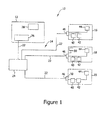
- FIG. 1 is a block diagram of an exemplary energy production and transmission system 10 that includes an electric utility 12, a power grid 14, and a plurality of customer locations 16, 18, and 20. Electricity is delivered from electric utility 12 to customer locations 16, 18, and 20 via electric power grid 14.
- electric power grid 14 includes a plurality of transmission lines 22 and an electrical substation 24.
- Electric utility 12 includes an electric generator 26 that supplies electrical power to power grid 14. Generator 26 may be driven by, for example, a gas turbine engine, a hydroelectric turbine, and/or a wind turbine.
- Electric utility 12 also includes a computer system 28 configured to control energy production and transmission. Computer system 28 is illustrated as being included within electric utility 12, however, computer system 28 may be external to electric utility 12 (e.g., remotely located) and in communication with electric utility 12.
- computer system 28 may be any suitable processing device that enables energy production and transmission system 10 to function as described herein.
- computer system 28 is further configured as part of a demand side load shedding system, described in more detail below.
- Customer locations 16, 18, and 20 include electric loads, for example, loads 40, 42, and 44. Moreover, customer locations 16, 18, and 20 also include an enclosure. The enclosure is referred to herein as an electrical load center, and more specifically, as an electrical panel 46. Electrical panel 46 may also be referred to as a circuit breaker box or a fuse box. Loads 40, 42, and 44 are coupled to electrical panel 46. Electrical panel 46 is also coupled to power grid 14 and receives electricity for use throughout customer location 16, 18, and/or 20. Electrical panel 46 divides the electricity provided into varying values of current for delivery to individual circuits within customer location 16, 18, and/or 20, and more specifically, to loads 40, 42, and 44.
- Electrical panel 46 includes a plurality of circuit protection devices (not shown in Figure 1 ), for example, circuit breakers and/or fuses, configured to interrupt the flow of electricity to a portion of customer location 16, 18, and/or 20 if that location is drawing more than a predefined level of current.
- Some circuit protection devices for example, circuit breakers, also allow electricity to be intentionally turned off to a corresponding circuit within customer location 16, 18, and/or 20.
- a circuit breaker may be intentionally turned off to allow a user to perform electrical repairs in a specific location within customer location 16, 18, and/or 20, or to turn off a specific device/appliance to conserve electricity.
- FIG 2 is a block diagram of an exemplary load shedding system 80 that may be included within energy production and transmission system 10 (shown in Figure 1 ).
- Load shedding system 80 facilitates controlling operation of an electrical load center that includes at least one circuit breaker, for example, electrical panel 46 (shown in Figure 1 ).
- the control of electrical panel 46 is provided without uncoupling the circuit breaker from electrical panel 46, and without interfering with normal functionality of electrical panel 46.
- electrical panel 46 many include any other type of circuit protection device that includes an actuator lever, or other type of electrical or mechanical device, that allows a user to reset the circuit protection device and/or to manually switch the circuit protection device between an "on" state and an "off/trip" state.
- load shedding system 80 includes a processing device 82 communicatively coupled to at least one load shedding apparatus 84.
- load shedding system 80 will include a plurality of load shedding apparatus 84, for example, a first load shedding apparatus 86, a second load shedding apparatus 88, a third load shedding apparatus 90, and a fourth load shedding apparatus 92.
- Load shedding apparatus 84 are coupled to a door (shown in Figure 4 ) of electrical panel 46 and are operatively coupled to at least one circuit breaker actuator lever (shown in Figure 4 ) within electrical panel 46.
- Each load shedding apparatus 48 is of an appropriate size and geometry that every circuit breaker included within electrical panel 46 may be outfitted with a load shedding apparatus 48.
- load shedding system 80 may include any number of load shedding apparatus that allow load shedding system 80 to function as described herein.
- the number of load shedding apparatus 84 corresponds to a number of circuit breaker actuator levers (shown in Figure 4 ) that load shedding system 80 is configured to control.
- multiple load shedding apparatus 84 are operatively coupled to a single circuit breaker actuator lever, and work in unison to operate the circuit breaker actuator lever.
- processor refers to central processing units, microprocessors, microcontrollers, reduced instruction set circuits (RISC), application specific integrated circuits (ASIC), logic circuits, and any other circuit or processor capable of executing the functions described herein.
- RISC reduced instruction set circuits
- ASIC application specific integrated circuits
- processing device 82 generates a load shedding signal 94 in response to a demand signal 96 from a demand signaling device 98.
- demand signaling device 98 is controlled by electric utility 12 (shown in Figure 1 ).
- demand signaling device 98 may be controlled by, or included within, computer system 28 (shown in Figure 1 ).
- demand signaling device 98 When electric utility 12 determines that shedding loads from system 10 would be beneficial, demand signaling device 98 generates demand signal 96 and transmits demand signal 96 to processor 82.
- Demand signal 96 may include generic instructions instructing processor 82 to shed a load.
- Processor 82 may include a memory 100 preprogrammed with an order in which loads, for example, loads 40, 42, and 44, are to be shed.
- Demand signal 96 may include more detailed instructions, for example, instructions instructing processor 82 to shed a specific load, for example, load 40. Furthermore, demand signal 96 may include a specific load shedding request, for example, an instruction instructing processor 82 to shed a specified level of electrical usage. Memory 100 may be preprogrammed with a typical energy usage of loads 40, 42, and 44, and processor 82 may be programmed to determine which loads to shed in order to meet the demand associated with demand signal 96.
- demand signaling device 98 is controlled by a customer or a user, for example, a customer at customer location 16, 18, and/or 20 (shown in Figure 1 ).
- a customer programs demand signaling device 98 with instructions as to when the customer wants loads to be shed.
- a customer may program demand signaling device 98 with a daily schedule of when specific non-essential loads are to be shed, for example, when a pool pump or a water heater should be turned off. The customer may base this decision on tiered energy prices set by electric utility 12 (shown in Figure 1 ).
- demand signal 96 may include any instructions/data that allow load shedding system 80 to function as described herein.
- processor 82 in response to demand signal 96, processor 82 generates load shedding signal 94 and transmits load shedding signal 94 to at least one of load shedding apparatus 84.
- Processor 82 determines which of load shedding apparatus 84 to operate based on information stored in memory 100 and/or on the contents of demand signal 96.
- a load shedding apparatus for example, load shedding apparatus 86, mechanically sheds a corresponding load by actuating a circuit breaker from an "on" state to an "off' state.
- load shedding apparatus 86 actuates the circuit breaker from the "on” state to the "off' state, load shedding apparatus 86 returns to a neutral position where the functionality of electrical panel 46 is not affected by the presence of load shedding apparatus 86.
- the functionality of electrical panel 46, and more specifically, each circuit breaker includes positioning the circuit breaker in a first position or in a second position (e.g., an "on” state or an "off” state). For example, with load shedding apparatus 86 in the neutral position, a user may open the door of electrical panel 46, change a state of circuit breakers therein, and close the door of electrical panel 46 without any interference from load shedding apparatus 86.
- load shedding system 80 facilitates shedding of an attached load.
- load shedding system 80 also performs the operations described above to reenergize the attached load.
- demand signal 96 may include instructions instructing processor 82 to add a load to power grid 14.
- Such a demand signal may be sent by electric utility 12 after peak hours, when overall energy demand is reduced to lower than a predefined level.
- a customer may program demand signaling device 98 to reenergize an attached load at a time when energy rates return to non-peak levels.
- FIG 3 is a perspective view of load shedding apparatus 86 (shown in Figure 2 ).
- Load shedding apparatus 86 includes a first end 102 and a second end 104.
- load shedding apparatus 86 includes an actuator 106.
- actuator 106 is a linear actuator that includes an electric motor 112, a first threaded member 114, at least one guide member 116, and a second threaded member 118.
- actuator 106 may be any suitable type of actuator that allows load shedding apparatus 86 to function as described herein.
- second threaded member 118 is complementary to first threaded member 114.
- first threaded member 114 is a lead screw and second threaded member 118 is a moving nut.
- Load shedding apparatus 86 also includes an interface member, referred to herein as a breaker handle 120.
- breaker handle 120 is coupled to moving nut 118.
- breaker handle 120 includes moving nut 118.
- Moving nut 118 is operatively coupled to lead screw 114.
- Electric motor 112 is coupled to and configured to rotate lead screw 114.
- Rotating lead screw 114 in a first direction 122 e.g., clockwise
- Rotating lead screw 114 in a second direction 126 (e.g., counterclockwise), opposite to first direction 122, causes moving nut 118 to translate in a second direction 128, opposite to first direction 124.
- Guide member 116 includes, for example, at least one guide rod. Guide member 116 prevents moving nut 118 from rotating with respect to lead screw 114.
- Load shedding apparatus 86 may also include gearing 130, for example, a gear box, that couples electric motor 112 to lead screw 114.
- Gearing 130 causes lead screw 114 to rotate at a lower rate than electric motor 112, but increases the torque applied by lead screw 114 on moving nut 118.
- Gearing 130 increases the torque to a level required to move an actuator lever of a circuit breaker (shown in Figure 4 ) between positions.
- Gearing 130 also facilitates use of a smaller motor, while obtaining the torque level needed to move the actuator lever, therefore a more compact load shedding apparatus 86 can be produced.
- Load shedding apparatus 86 may also include a mounting plate 132. Mounting plate 132 is configured to facilitate coupling load shedding apparatus 86 to a door of electrical panel 46 (shown in Figure 4 ). Load shedding apparatus 86 may also include a guide couple 134, which couples guide member 116 to electric motor 112. Furthermore, load shedding apparatus 86 may include a bearing housing, for example, but not limited to, a pillow block 136. Pillow block 136 is operatively coupled to second end 104 of lead screw 114 and facilitates efficient rotation of lead screw 114.
- breaker handle 120 includes a base plate 138 coupled to and/or including moving nut 118.
- Breaker handle 120 also includes a first edge 140 extending substantially perpendicularly from first end 102 of base plate 138.
- Breaker handle 120 also includes a second edge 142 extending substantially perpendicularly from second end 104 of base plate 138.
- first edge 140 is substantially parallel to second edge 142.
- First edge 140 and second edge 142 each include an inner surface 144 and 146, respectively.
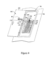
- FIG 4 is a perspective view of load shedding apparatus 86 coupled to a door 160 of electrical panel 46.
- Electrical panel door 160 is in an open position relative to electrical panel 46.
- Figure 5 is a perspective view of load shedding apparatus 86 coupled to electrical panel door 160.
- door 160 is illustrated as transparent in order to show the position of load shedding apparatus 86 when door 160 is closed relative to electrical panel 46.
- Electrical panel door 160 includes an interior surface 162 and an exterior surface 164. When closed, door 160 and electrical panel 46 define an interior 166 of electrical panel 46, which encloses a plurality of individual circuit breakers, for example, first circuit breaker 170, second circuit breaker 172, third circuit breaker 174, fourth circuit breaker 176, fifth circuit breaker 178, and sixth circuit breaker 180.
- circuit breakers 170, 172, 174, 176, 178, and 180 are electrical switches that automatically operate to disconnect an electrical circuit from a power source upon the occurrence of a fault, for example, a short circuit, and also allow manual switching between an "on” state and an "off/tripped" state.
- Circuit breakers 170, 172, 174, 176, 178, and 180 each include an actuator lever 182 for manual operation of the circuit breaker.
- Actuator lever 182 is movable between a first position 184 and a second position 186.
- First position 184 is referred to herein as an "on" position.
- Circuit breakers 170, 172, 174, 176, 178, and 180 operate as a closed circuit when in the "on" position, allowing electricity to flow from power grid 14 to loads coupled to the circuit breaker.
- Second position 186 is referred to herein as an "off/tripped" position.
- Circuit breakers 170, 172, 174, 176, 178, and 180 operate as an open circuit when in the "off/tripped” position, preventing electricity from flowing through the circuit breaker.
- an individual circuit within customer location 16 may be turned off by manually switching actuator lever 182 from “on” position 184 to "off/tripped” position 186.
- a circuit breaker that has automatically switched from “on” position 184 to "off/tripped” position 186 due to current drawn by loads coupled to the circuit breaker exceeding a predefined current level may be reset by a user by manually switching actuator lever 182 from "off/tripped” position 186 to "on” position 184.
- mounting plate 132 is coupled to interior surface 162 of door 160 and facilitates coupling load shedding apparatus 86 to door 160.
- Load shedding apparatus 86 may be coupled to door 160 using a fastener such as, but not limited to, a screw or an adhesive (not shown in Figure 3 ).
- portions of load shedding apparatus 86 fit between circuit breakers, for example, between first circuit breaker 170 and third circuit breaker 174. More specifically, base plate 138 and moving nut 118 have a thickness 200 (shown in Figure 3 ) that is less than a distance 210 (shown in Figure 4 ) between actuator lever 182 of first circuit breaker 170 and actuator lever 182 of third circuit breaker 174.
- Figure 6 is a top view of actuator lever 182 of third circuit breaker 174 positioned in first position 184.
- breaker handle 120 is translated in first direction 124 through operation of load shedding apparatus 86.
- Inner surface 146 of second edge 142 forces actuator lever 182 into first position 184 (e.g., "on" position).
- Figure 7 is a top view of actuator lever 182 of third circuit breaker 174 positioned in second position 186.
- breaker handle 120 is translated in second direction 128 through operation of load shedding apparatus 86.
- Inner surface 144 of first edge 140 forces actuator lever 182 into second position 186 (e.g., "off/tripped" position).
- Load shedding apparatus 86 ensures that actuator lever 182 is in a position requested in load shedding signal 94 (shown in Figure 2 ). If load shedding signal 94 directs load shedding apparatus 86 to switch third circuit breaker 174 to "on” position 184, and third circuit breaker 174 is already in “on” position 184, load shedding apparatus 86 will still translate breaker handle 120 in first direction 124, ensuring that third circuit breaker 174 is in "on” position 184.
- load shedding apparatus 86 directs load shedding apparatus 86 to switch third circuit breaker 174 to "off/tripped" position 186, and third circuit breaker 174 is already in “off/tripped” position 186, load shedding apparatus 86 will still translate breaker handle 120 in second direction 128, ensuring that third circuit breaker 174 is in "off/tripped” position 186.
- FIG 8 is a top view of load shedding apparatus 86 in a neutral position 220.
- load shedding apparatus 86 translates breaker handle 120 to either first position 184 (shown in Figure 6 ) or second position 186 (shown in Figure 7 )
- load shedding apparatus 86 returns breaker handle 120 to neutral position 220.
- a distance 222 between inner surface 144 of first edge 140 and inner surface 146 of second edge 142 corresponds to a distance 224 between a first edge 230 (shown in Figure 6 ) of breaker lever 182 in "on" position 184 and a second edge 232 (shown in Figure 7 ) of breaker lever 182 in "off/tripped" position 186.
- distance 222 is greater than distance 224.
- Distance 224 between first edge 230 of breaker lever 182 in position 184 and second edge 232 of breaker lever 182 in position 186 is also referred to herein as a throw distance of circuit breaker 174.
- breaker handle 120 of third circuit breaker 174 is in "off/tripped" position 186. A user may decide they would like to manually return third circuit breaker 174 to "on" position 184.
- door 160 opens door 160 and physically switches breaker handle 120 to "on” position 184. Even though actuator lever 182 was in "off/trip” position 186 when the user opened door 160 and was switched to "on” position 184, door 160 closes without interference between load shedding apparatus 86 and actuator lever 182, or between load shedding apparatus 86 and any other component within interior 166 of electrical panel 46.
- Figure 9 is a flow chart 250 of an exemplary method 252 for retrofitting an electrical load center, for example, electrical load center 46 (shown in Figure 2 ) to include load shedding system 80 (shown in Figure 2 ).
- method 252 includes configuring 260 a processor, for example, processor 82 (shown in Figure 2 ), to receive a demand signal from a demand signaling device, for example, demand signaling device 98 that provides a demand response signal, for example, demand response signal 96 (shown in Figure 2 ) to processor 82.
- Configuring 260 may include coupling processor 82 to demand signaling device 98 using an electrical wire or other communication cable.
- Configuring 260 may also include communicatively coupling processor 82 and demand signaling device 98 using, for example, cellular technology.
- Processor 82 is coupled to at least one of an electric utility, for example, electric utility 12 (shown in Figure 1 ), that provides demand response signal 96 to the processor and a customer location demand signaling device.
- Method 252 also includes communicatively coupling 262 processor 82 to at least one load shedding apparatus, for example, load shedding apparatus 86.
- Method 252 also includes configuring 264 load shedding apparatus 86 to be coupled to a door, for example, door 160 (shown in Figure 4 ) of an electrical load center, for example, electrical panel 46 (shown in Figure 4 ).
- Load shedding apparatus 86 is coupled to door 160 in such a manner that when door 160 is closed, load shedding apparatus 86 is operatively coupled to at least one circuit breaker switch within electrical panel 46.
- load shedding apparatus 86 is configured 264 to be coupled to door 160 in such a manner that load shedding system 80 does not interfere with normal functionality of electrical panel 46.
- a user may open door 160, change the position of actuator levers 182 (shown in Figure 4 ) of any of the circuit breakers included in electrical panel 46, and close door 160 without interference from load shedding apparatus 86 or any component of load shedding system 80.
- Method 252 also includes configuring 266 load shedding apparatus 86 to move from a neutral position, for example, neutral position 220 (shown in Figure 8 ) to a second position, for example, second position 186 (shown in Figure 7 ) in response to a load shedding signal, for example, load shedding signal 94 (shown in Figure 2 ) from processor 82. Since breaker handle 120 (shown in Figure 4 ) of load shedding apparatus 86 is operatively coupled to actuator lever 182, translating breaker handle 120 from neutral position 220 to second position 186, ensures that actuator lever 182 is also in second position 186. In the exemplary embodiment, second position 186 corresponds to an "off/tripped" state of circuit breaker 174. Configuring 266 load shedding apparatus 86 further comprises configuring load shedding apparatus 86 to return to neutral position 220 after reaching second position 186.
- a load shedding signal for example, load shedding signal 94 (shown in Figure 2 ) from processor 82. Since breaker handle 120 (shown in Figure
- Method 252 also includes configuring 268 load shedding apparatus 86 to move from neutral position 220 to a first position, for example first position 184 (shown in Figure 6 ) in response to load shedding signal 94 from processor 82.
- load shedding signal 94 is a reenergizing signal. Since breaker handle 120 (shown in Figure 4 ) of load shedding apparatus 86 is operatively coupled to actuator lever 182, translating breaker handle 120 from neutral position 220 to first position 184, ensures that actuator lever 182 is also in first position 184.
- first position 184 corresponds to an "on" state of circuit breaker 174.
- Configuring 268 load shedding apparatus 86 further comprises configuring load shedding apparatus 86 to return to neutral position 220 after reaching first position 184.
- Described herein are exemplary methods, systems, and apparatus for disconnecting a load from an electrical power distribution system. More specifically, the methods, systems, and apparatus described herein facilitate retrofitting an electrical load center with load shedding apparatus that changes a state of circuit breakers by mechanically moving the circuit breaker actuator levers to a directed state. The methods, systems, and apparatus described herein return a breaker handle to a neutral position after a load shedding movement is complete so that load shedding apparatus does not interfere with normal operation (e.g., manual operation) of the electrical load center.
- the coupling of load shedding apparatus to electrical load center door allows the load shedding system to adhere to electrical codes that require that such a system not interfere with normal operation of the electrical load center (e.g., codes that require that the system not restrict access to actuator levers).
- Coupling load shedding apparatus to electrical load center door also allows any wires leading to load shedding apparatus to be kept separate from incoming voltage lines leading into the electrical load center.
- the methods, systems, and apparatus described herein also facilitate controlling a state of a circuit breaker without an installation that requires uncoupling the circuit breaker from an electric supply, which is a job that may require considerably more labor and more costly equipment.
- the load shedding apparatus may be installed within the electrical load center while circuit breakers are coupled to the electric supply.
- the small size of the load shedding apparatus facilitates providing every circuit breaker actuator handle with a separate load shedding apparatus. Moreover, the small size of the load shedding apparatus facilitates use of more than one load shedding apparatus to actuate an actuator lever that requires more force to move than load shedding apparatus is able to provide.
- the methods, systems, and apparatus described herein facilitate efficient and economical shedding of loads from an electrical grid. Exemplary embodiments of methods, systems, and apparatus are described and/or illustrated herein in detail. The methods, systems, and apparatus are not limited to the specific embodiments described herein, but rather, components of each system and apparatus, as well as steps of each method, may be utilized independently and separately from other components and steps described herein. Each component, and each method step, can also be used in combination with other components and/or method steps.
Landscapes
- Engineering & Computer Science (AREA)
- Power Engineering (AREA)
- Remote Monitoring And Control Of Power-Distribution Networks (AREA)
- Keying Circuit Devices (AREA)
- Distribution Board (AREA)
- Supply And Distribution Of Alternating Current (AREA)
Abstract
Description
- The embodiments described herein relate generally to electrical power distribution systems and, more specifically, to managing electricity demand.
- In many regions of the world, demand for electricity is nearing electricity generation and delivery capacity. If current capacity remains the same and demand continues to rise, demand will exceed capacity. Generation and delivery capacity depends on both the amount of electricity an electrical utility is able to generate and the amount of electricity the electrical grid connecting the utility to the end users is able to deliver. If demand exceeds capacity, one result may be rolling black-outs where neighborhoods do not receive electricity during peak times of day. Another potential result is rolling brown-outs, where neighborhoods receive lower voltages, which may potentially cause damage to appliances and other equipment.
- The rising demand for electricity can be satisfied by increasing electricity generation capacity by constructing new power plants which could include wind, nuclear, solar, gas, and/or coal generation technologies. To deliver the increased electricity generated, the capacity of the electrical grid may also need to be increased. Such construction is expensive and time consuming. Environmental concerns and energy price volatility are also constraints on merely adding conventional power generation facilities to meet the increasing demand.
- Businesses and home owners may also install green technologies such as solar cells to generate their own electricity locally and decrease the strain on the grid. However, the upfront costs for these solutions are high, preventing widespread implementation.
- Reducing demand during peak hours is another way to prevent demand for electricity from surpassing electricity generation and delivery capacity. Electricity consumption varies throughout a typical day. However, each day the electricity demand curve of electricity consumption varies in a similar manner. For example, during peak times (i.e., morning to early evening), demand for electricity is highest. Demand for electricity is significantly lower early in the morning and late at night. Power storage devices may be charged during non-peak times of the day, which increases the demand during those times of day. The power that is stored can then be used during times of peak demand. This flattens the electricity demand curve by creating a constant demand below capacity limits. However, the cost of current battery technology capable of charging to this high of an energy level is prohibitive.
- Demand for electricity at peak times may be passively reduced by an electric utility by increasing the cost of electricity during peak hours. Higher energy costs may motivate customers to reduce electricity usage. This passive solution requires cooperation of the end user as well as action by the end user to remove electrical loads from the grid during peak hours. Some solutions currently exist, such as programmable thermostats, that automatically reduce usage of a high power-usage load during peak hours. Such solutions typically are very limited in the types of devices they control. Demand for electricity may also be actively reduced by an electric utility by taking action to remove electrical loads. For example, a "smart grid" allows a utility to send a signal instructing a "smart device" at a customer location to turn itself off. Typically, equipment used by electric utilities to automatically shed loads from the electric grid requires costly installation at a customer location, many times, requiring the expertise of an electrician.
- In one aspect, a load shedding system for operating at least one circuit breaker positioned within an enclosure is provided. The load shedding system includes a processor configured to receive a demand signal and to provide a predetermined load shedding signal. The load shedding system also includes at least one load shedding apparatus configured to receive the load shedding signal from the processor. The load shedding apparatus is configured to be coupled to a door of the enclosure. The load shedding apparatus is further configured to be operatively coupled to the at least one circuit breaker and configured to actuate the at least one circuit breaker in response to the load shedding signal.
- In another aspect, a load shedding apparatus for operating at least one circuit breaker included within an enclosure is provided. The enclosure includes a door. The load shedding apparatus includes an interface member that includes a first edge and a second edge, the interface member operatively coupled to the at least one circuit breaker. The load shedding apparatus also includes an actuator configured to translate the interface member from a neutral position to a first position in response to a load shedding signal.
- In yet another aspect, a method for retrofitting an electrical load center with a load shedding system is provided. The load shedding system includes a processor and at least one load shedding apparatus. The method includes configuring the processor to receive a demand signal. The method also includes communicatively coupling the processor to the at least one load shedding apparatus. The method also includes configuring the at least one load shedding apparatus to be coupled to a door of the electrical load center such that when the door is in a first door position, the at least one load shedding apparatus is operatively coupled to at least one circuit breaker within the electrical load center.
-
-
Figure 1 is a block diagram of an exemplary energy production and transmission system that includes an electric utility, a power grid, and a plurality of customer locations. -
Figure 2 is a block diagram of an exemplary load shedding system that may be included within the energy production and transmission system shown inFigure 1 . -
Figure 3 is a perspective view of an exemplary load shedding apparatus that may be included within the load shedding system shown inFigure 2 . -
Figure 4 is a perspective view of the load shedding apparatus shown inFigure 3 coupled to an open electrical load center door. -
Figure 5 is a perspective view of the load shedding apparatus shown inFigure 3 coupled to a closed electrical load center door. -
Figure 6 is a top view of the load shedding apparatus shown inFigure 3 positioned in a first position. -
Figure 7 is a top view of the load shedding apparatus shown inFigure 3 positioned in a second position. -
Figure 8 is a top view of the load shedding apparatus shown inFigure 3 positioned in a neutral position. -
Figure 9 is a flow chart of an exemplary method for retrofitting an electrical load center with the load shedding system shown inFigure 2 . - The embodiments described herein include a load shedding system for use by end users in an energy production and transmission system. The system facilitates automatically managing electrical demand based on load shedding signals and/or a preset schedule.
- A first technical effect of the energy production and transmission system described herein is to provide direct control of loads included within the transmission system. The first technical effect is at least partially achieved by (a) receiving a demand response signal at a processor, (b) providing a load shedding signal, generated at the processor, to at least one load shedding apparatus, and (c) actuating the load shedding apparatus from a first position to a second position in response to the load shedding signal. The direct control of loads is provided without uncoupling a circuit protection device from the source of electricity, and without interfering with normal functionality of the circuit protection device.
-
Figure 1 is a block diagram of an exemplary energy production andtransmission system 10 that includes anelectric utility 12, apower grid 14, and a plurality ofcustomer locations electric utility 12 tocustomer locations electric power grid 14. In the exemplary embodiment,electric power grid 14 includes a plurality oftransmission lines 22 and anelectrical substation 24.Electric utility 12 includes anelectric generator 26 that supplies electrical power topower grid 14.Generator 26 may be driven by, for example, a gas turbine engine, a hydroelectric turbine, and/or a wind turbine.Electric utility 12 also includes acomputer system 28 configured to control energy production and transmission.Computer system 28 is illustrated as being included withinelectric utility 12, however,computer system 28 may be external to electric utility 12 (e.g., remotely located) and in communication withelectric utility 12. Furthermore, although described as a computer system,computer system 28 may be any suitable processing device that enables energy production andtransmission system 10 to function as described herein. In the exemplary embodiment,computer system 28 is further configured as part of a demand side load shedding system, described in more detail below. -
Customer locations customer locations electrical panel 46.Electrical panel 46 may also be referred to as a circuit breaker box or a fuse box.Loads electrical panel 46.Electrical panel 46 is also coupled topower grid 14 and receives electricity for use throughoutcustomer location Electrical panel 46 divides the electricity provided into varying values of current for delivery to individual circuits withincustomer location loads Electrical panel 46 includes a plurality of circuit protection devices (not shown inFigure 1 ), for example, circuit breakers and/or fuses, configured to interrupt the flow of electricity to a portion ofcustomer location customer location customer location -
Figure 2 is a block diagram of an exemplaryload shedding system 80 that may be included within energy production and transmission system 10 (shown inFigure 1 ). -
Load shedding system 80 facilitates controlling operation of an electrical load center that includes at least one circuit breaker, for example, electrical panel 46 (shown inFigure 1 ). The control ofelectrical panel 46 is provided without uncoupling the circuit breaker fromelectrical panel 46, and without interfering with normal functionality ofelectrical panel 46. Although described herein as including at least one circuit breaker,electrical panel 46 many include any other type of circuit protection device that includes an actuator lever, or other type of electrical or mechanical device, that allows a user to reset the circuit protection device and/or to manually switch the circuit protection device between an "on" state and an "off/trip" state. - In the exemplary embodiment,
load shedding system 80 includes aprocessing device 82 communicatively coupled to at least one load shedding apparatus 84. Typically,load shedding system 80 will include a plurality of load shedding apparatus 84, for example, a firstload shedding apparatus 86, a secondload shedding apparatus 88, a thirdload shedding apparatus 90, and a fourthload shedding apparatus 92. Load shedding apparatus 84 are coupled to a door (shown inFigure 4 ) ofelectrical panel 46 and are operatively coupled to at least one circuit breaker actuator lever (shown inFigure 4 ) withinelectrical panel 46. Each load shedding apparatus 48 is of an appropriate size and geometry that every circuit breaker included withinelectrical panel 46 may be outfitted with a load shedding apparatus 48. - Although illustrated as including four load shedding apparatus 84,
load shedding system 80 may include any number of load shedding apparatus that allowload shedding system 80 to function as described herein. In the exemplary embodiment, the number of load shedding apparatus 84 corresponds to a number of circuit breaker actuator levers (shown inFigure 4 ) thatload shedding system 80 is configured to control. In an alternative embodiment, multiple load shedding apparatus 84 are operatively coupled to a single circuit breaker actuator lever, and work in unison to operate the circuit breaker actuator lever. Furthermore, the term processor, or processing device, as used herein, refers to central processing units, microprocessors, microcontrollers, reduced instruction set circuits (RISC), application specific integrated circuits (ASIC), logic circuits, and any other circuit or processor capable of executing the functions described herein. - In the exemplary embodiment,
processing device 82 generates aload shedding signal 94 in response to ademand signal 96 from ademand signaling device 98. In the exemplary embodiment,demand signaling device 98 is controlled by electric utility 12 (shown inFigure 1 ). For example,demand signaling device 98 may be controlled by, or included within, computer system 28 (shown inFigure 1 ). Whenelectric utility 12 determines that shedding loads fromsystem 10 would be beneficial,demand signaling device 98 generatesdemand signal 96 and transmitsdemand signal 96 toprocessor 82.Demand signal 96 may include genericinstructions instructing processor 82 to shed a load.Processor 82 may include amemory 100 preprogrammed with an order in which loads, for example, loads 40, 42, and 44, are to be shed.Demand signal 96 may include more detailed instructions, for example,instructions instructing processor 82 to shed a specific load, for example,load 40. Furthermore,demand signal 96 may include a specific load shedding request, for example, aninstruction instructing processor 82 to shed a specified level of electrical usage.Memory 100 may be preprogrammed with a typical energy usage ofloads processor 82 may be programmed to determine which loads to shed in order to meet the demand associated withdemand signal 96. - In an alternative embodiment,
demand signaling device 98 is controlled by a customer or a user, for example, a customer atcustomer location Figure 1 ). In the alternative embodiment, a customer programs demand signalingdevice 98 with instructions as to when the customer wants loads to be shed. For example, a customer may programdemand signaling device 98 with a daily schedule of when specific non-essential loads are to be shed, for example, when a pool pump or a water heater should be turned off. The customer may base this decision on tiered energy prices set by electric utility 12 (shown inFigure 1 ). Although described herein as including a generic load shedding request and/or a specific load shedding request fromelectric utility 12, and/or a load shedding request from the customer,demand signal 96 may include any instructions/data that allowload shedding system 80 to function as described herein. - In the exemplary embodiment, in response to demand
signal 96,processor 82 generatesload shedding signal 94 and transmitsload shedding signal 94 to at least one of load shedding apparatus 84.Processor 82 determines which of load shedding apparatus 84 to operate based on information stored inmemory 100 and/or on the contents ofdemand signal 96. In response to load sheddingsignal 94, a load shedding apparatus, for example, load sheddingapparatus 86, mechanically sheds a corresponding load by actuating a circuit breaker from an "on" state to an "off' state. Onceload shedding apparatus 86 actuates the circuit breaker from the "on" state to the "off' state,load shedding apparatus 86 returns to a neutral position where the functionality ofelectrical panel 46 is not affected by the presence ofload shedding apparatus 86. The functionality ofelectrical panel 46, and more specifically, each circuit breaker, includes positioning the circuit breaker in a first position or in a second position (e.g., an "on" state or an "off" state). For example, withload shedding apparatus 86 in the neutral position, a user may open the door ofelectrical panel 46, change a state of circuit breakers therein, and close the door ofelectrical panel 46 without any interference fromload shedding apparatus 86. - As described above,
load shedding system 80 facilitates shedding of an attached load. In the exemplary embodiment,load shedding system 80 also performs the operations described above to reenergize the attached load. For example,demand signal 96 may includeinstructions instructing processor 82 to add a load topower grid 14. Such a demand signal may be sent byelectric utility 12 after peak hours, when overall energy demand is reduced to lower than a predefined level. Alternatively, a customer may programdemand signaling device 98 to reenergize an attached load at a time when energy rates return to non-peak levels. -
Figure 3 is a perspective view of load shedding apparatus 86 (shown inFigure 2 ).Load shedding apparatus 86 includes afirst end 102 and asecond end 104. In the exemplary embodiment,load shedding apparatus 86 includes an actuator 106. In the exemplary embodiment, actuator 106 is a linear actuator that includes anelectric motor 112, a first threadedmember 114, at least oneguide member 116, and a second threadedmember 118. Although described herein as a linear actuator, actuator 106 may be any suitable type of actuator that allowsload shedding apparatus 86 to function as described herein. In the exemplary embodiment, second threadedmember 118 is complementary to first threadedmember 114. In a specific example, first threadedmember 114 is a lead screw and second threadedmember 118 is a moving nut.Load shedding apparatus 86 also includes an interface member, referred to herein as abreaker handle 120. In the exemplary embodiment,breaker handle 120 is coupled to movingnut 118. In an alternative embodiment,breaker handle 120 includes movingnut 118. Movingnut 118 is operatively coupled to leadscrew 114.Electric motor 112 is coupled to and configured to rotatelead screw 114. Rotatinglead screw 114 in a first direction 122 (e.g., clockwise) causes movingnut 118 to translate in afirst direction 124. Rotatinglead screw 114 in a second direction 126 (e.g., counterclockwise), opposite tofirst direction 122,causes moving nut 118 to translate in asecond direction 128, opposite tofirst direction 124.Guide member 116 includes, for example, at least one guide rod.Guide member 116 prevents movingnut 118 from rotating with respect to leadscrew 114. -
Load shedding apparatus 86 may also include gearing 130, for example, a gear box, that coupleselectric motor 112 to leadscrew 114. Gearing 130 causeslead screw 114 to rotate at a lower rate thanelectric motor 112, but increases the torque applied bylead screw 114 on movingnut 118. Gearing 130 increases the torque to a level required to move an actuator lever of a circuit breaker (shown inFigure 4 ) between positions. Gearing 130 also facilitates use of a smaller motor, while obtaining the torque level needed to move the actuator lever, therefore a more compactload shedding apparatus 86 can be produced. -
Load shedding apparatus 86 may also include a mountingplate 132. Mountingplate 132 is configured to facilitate couplingload shedding apparatus 86 to a door of electrical panel 46 (shown inFigure 4 ).Load shedding apparatus 86 may also include aguide couple 134, which couples guidemember 116 toelectric motor 112. Furthermore,load shedding apparatus 86 may include a bearing housing, for example, but not limited to, apillow block 136.Pillow block 136 is operatively coupled tosecond end 104 oflead screw 114 and facilitates efficient rotation oflead screw 114. - In the exemplary embodiment,
breaker handle 120 includes abase plate 138 coupled to and/or including movingnut 118.Breaker handle 120 also includes afirst edge 140 extending substantially perpendicularly fromfirst end 102 ofbase plate 138.Breaker handle 120 also includes asecond edge 142 extending substantially perpendicularly fromsecond end 104 ofbase plate 138. In the exemplary embodiment,first edge 140 is substantially parallel tosecond edge 142.First edge 140 andsecond edge 142 each include aninner surface -
Figure 4 is a perspective view ofload shedding apparatus 86 coupled to adoor 160 ofelectrical panel 46.Electrical panel door 160 is in an open position relative toelectrical panel 46.Figure 5 is a perspective view ofload shedding apparatus 86 coupled toelectrical panel door 160. InFigure 4 ,door 160 is illustrated as transparent in order to show the position ofload shedding apparatus 86 whendoor 160 is closed relative toelectrical panel 46.Electrical panel door 160 includes aninterior surface 162 and anexterior surface 164. When closed,door 160 andelectrical panel 46 define an interior 166 ofelectrical panel 46, which encloses a plurality of individual circuit breakers, for example,first circuit breaker 170,second circuit breaker 172,third circuit breaker 174,fourth circuit breaker 176,fifth circuit breaker 178, andsixth circuit breaker 180. As described above,circuit breakers -
Circuit breakers actuator lever 182 for manual operation of the circuit breaker.Actuator lever 182 is movable between afirst position 184 and asecond position 186.First position 184 is referred to herein as an "on" position.Circuit breakers power grid 14 to loads coupled to the circuit breaker.Second position 186 is referred to herein as an "off/tripped" position.Circuit breakers Figure 1 ) may be turned off by manually switchingactuator lever 182 from "on"position 184 to "off/tripped"position 186. Furthermore, a circuit breaker that has automatically switched from "on"position 184 to "off/tripped"position 186 due to current drawn by loads coupled to the circuit breaker exceeding a predefined current level, may be reset by a user by manually switchingactuator lever 182 from "off/tripped"position 186 to "on"position 184. - In the exemplary embodiment, mounting
plate 132 is coupled tointerior surface 162 ofdoor 160 and facilitates couplingload shedding apparatus 86 todoor 160.Load shedding apparatus 86 may be coupled todoor 160 using a fastener such as, but not limited to, a screw or an adhesive (not shown inFigure 3 ). - In the exemplary embodiment, when
door 160 is closed (shown inFigure 5 ), portions ofload shedding apparatus 86 fit between circuit breakers, for example, betweenfirst circuit breaker 170 andthird circuit breaker 174. More specifically,base plate 138 and movingnut 118 have a thickness 200 (shown inFigure 3 ) that is less than a distance 210 (shown inFigure 4 ) betweenactuator lever 182 offirst circuit breaker 170 andactuator lever 182 ofthird circuit breaker 174. -
Figure 6 is a top view ofactuator lever 182 ofthird circuit breaker 174 positioned infirst position 184. In the exemplary embodiment,breaker handle 120 is translated infirst direction 124 through operation ofload shedding apparatus 86.Inner surface 146 ofsecond edge 142 forces actuatorlever 182 into first position 184 (e.g., "on" position). -
Figure 7 is a top view ofactuator lever 182 ofthird circuit breaker 174 positioned insecond position 186. In the exemplary embodiment,breaker handle 120 is translated insecond direction 128 through operation ofload shedding apparatus 86.Inner surface 144 offirst edge 140 forces actuatorlever 182 into second position 186 (e.g., "off/tripped" position). -
Load shedding apparatus 86 ensures thatactuator lever 182 is in a position requested in load shedding signal 94 (shown inFigure 2 ). Ifload shedding signal 94 directsload shedding apparatus 86 to switchthird circuit breaker 174 to "on"position 184, andthird circuit breaker 174 is already in "on"position 184,load shedding apparatus 86 will still translate breaker handle 120 infirst direction 124, ensuring thatthird circuit breaker 174 is in "on"position 184. Similarly, ifload shedding signal 94 directsload shedding apparatus 86 to switchthird circuit breaker 174 to "off/tripped"position 186, andthird circuit breaker 174 is already in "off/tripped"position 186,load shedding apparatus 86 will still translate breaker handle 120 insecond direction 128, ensuring thatthird circuit breaker 174 is in "off/tripped"position 186. -
Figure 8 is a top view ofload shedding apparatus 86 in aneutral position 220. In the exemplary embodiment, afterload shedding apparatus 86 translatesbreaker handle 120 to either first position 184 (shown inFigure 6 ) or second position 186 (shown inFigure 7 ),load shedding apparatus 86 returns breaker handle 120 toneutral position 220. In the exemplary embodiment, adistance 222 betweeninner surface 144 offirst edge 140 andinner surface 146 ofsecond edge 142 corresponds to adistance 224 between a first edge 230 (shown inFigure 6 ) ofbreaker lever 182 in "on"position 184 and a second edge 232 (shown inFigure 7 ) ofbreaker lever 182 in "off/tripped"position 186. For example,distance 222 is greater thandistance 224. Distance 224 betweenfirst edge 230 ofbreaker lever 182 inposition 184 andsecond edge 232 ofbreaker lever 182 inposition 186 is also referred to herein as a throw distance ofcircuit breaker 174. Returning breaker handle 120 toneutral position 220, and configuringfirst edge 140 andsecond edge 142 to spandistance 222, facilitates preventingload shedding apparatus 86 from interfering with typical operation ofelectrical panel 46. In a specific example, whendoor 160 is closed, breaker handle 120 ofthird circuit breaker 174 is in "off/tripped"position 186. A user may decide they would like to manually returnthird circuit breaker 174 to "on"position 184. The user opensdoor 160 and physically switches breaker handle 120 to "on"position 184. Even thoughactuator lever 182 was in "off/trip"position 186 when the user openeddoor 160 and was switched to "on"position 184,door 160 closes without interference betweenload shedding apparatus 86 andactuator lever 182, or betweenload shedding apparatus 86 and any other component withininterior 166 ofelectrical panel 46. -
Figure 9 is aflow chart 250 of anexemplary method 252 for retrofitting an electrical load center, for example, electrical load center 46 (shown inFigure 2 ) to include load shedding system 80 (shown inFigure 2 ). In the exemplary embodiment,method 252 includes configuring 260 a processor, for example, processor 82 (shown inFigure 2 ), to receive a demand signal from a demand signaling device, for example,demand signaling device 98 that provides a demand response signal, for example, demand response signal 96 (shown inFigure 2 ) toprocessor 82. Configuring 260 may includecoupling processor 82 to demand signalingdevice 98 using an electrical wire or other communication cable. Configuring 260 may also include communicatively couplingprocessor 82 anddemand signaling device 98 using, for example, cellular technology.Processor 82 is coupled to at least one of an electric utility, for example, electric utility 12 (shown inFigure 1 ), that providesdemand response signal 96 to the processor and a customer location demand signaling device. -
Method 252 also includes communicatively coupling 262processor 82 to at least one load shedding apparatus, for example, load sheddingapparatus 86.Method 252 also includes configuring 264load shedding apparatus 86 to be coupled to a door, for example, door 160 (shown inFigure 4 ) of an electrical load center, for example, electrical panel 46 (shown inFigure 4 ).Load shedding apparatus 86 is coupled todoor 160 in such a manner that whendoor 160 is closed,load shedding apparatus 86 is operatively coupled to at least one circuit breaker switch withinelectrical panel 46. Furthermore,load shedding apparatus 86 is configured 264 to be coupled todoor 160 in such a manner that loadshedding system 80 does not interfere with normal functionality ofelectrical panel 46. For example, a user may opendoor 160, change the position of actuator levers 182 (shown inFigure 4 ) of any of the circuit breakers included inelectrical panel 46, andclose door 160 without interference fromload shedding apparatus 86 or any component ofload shedding system 80. -
Method 252 also includes configuring 266load shedding apparatus 86 to move from a neutral position, for example, neutral position 220 (shown inFigure 8 ) to a second position, for example, second position 186 (shown inFigure 7 ) in response to a load shedding signal, for example, load shedding signal 94 (shown inFigure 2 ) fromprocessor 82. Since breaker handle 120 (shown inFigure 4 ) ofload shedding apparatus 86 is operatively coupled toactuator lever 182, translating breaker handle 120 fromneutral position 220 tosecond position 186, ensures thatactuator lever 182 is also insecond position 186. In the exemplary embodiment,second position 186 corresponds to an "off/tripped" state ofcircuit breaker 174. Configuring 266load shedding apparatus 86 further comprises configuringload shedding apparatus 86 to return toneutral position 220 after reachingsecond position 186. -
Method 252 also includes configuring 268load shedding apparatus 86 to move fromneutral position 220 to a first position, for example first position 184 (shown inFigure 6 ) in response to load sheddingsignal 94 fromprocessor 82. In this case,load shedding signal 94 is a reenergizing signal. Since breaker handle 120 (shown inFigure 4 ) ofload shedding apparatus 86 is operatively coupled toactuator lever 182, translating breaker handle 120 fromneutral position 220 tofirst position 184, ensures thatactuator lever 182 is also infirst position 184. In the exemplary embodiment,first position 184 corresponds to an "on" state ofcircuit breaker 174. Configuring 268load shedding apparatus 86 further comprises configuringload shedding apparatus 86 to return toneutral position 220 after reachingfirst position 184. - Described herein are exemplary methods, systems, and apparatus for disconnecting a load from an electrical power distribution system. More specifically, the methods, systems, and apparatus described herein facilitate retrofitting an electrical load center with load shedding apparatus that changes a state of circuit breakers by mechanically moving the circuit breaker actuator levers to a directed state. The methods, systems, and apparatus described herein return a breaker handle to a neutral position after a load shedding movement is complete so that load shedding apparatus does not interfere with normal operation (e.g., manual operation) of the electrical load center. The coupling of load shedding apparatus to electrical load center door allows the load shedding system to adhere to electrical codes that require that such a system not interfere with normal operation of the electrical load center (e.g., codes that require that the system not restrict access to actuator levers). Coupling load shedding apparatus to electrical load center door also allows any wires leading to load shedding apparatus to be kept separate from incoming voltage lines leading into the electrical load center. The methods, systems, and apparatus described herein also facilitate controlling a state of a circuit breaker without an installation that requires uncoupling the circuit breaker from an electric supply, which is a job that may require considerably more labor and more costly equipment. For example, the load shedding apparatus may be installed within the electrical load center while circuit breakers are coupled to the electric supply. The small size of the load shedding apparatus facilitates providing every circuit breaker actuator handle with a separate load shedding apparatus. Moreover, the small size of the load shedding apparatus facilitates use of more than one load shedding apparatus to actuate an actuator lever that requires more force to move than load shedding apparatus is able to provide.
- The methods, systems, and apparatus described herein facilitate efficient and economical shedding of loads from an electrical grid. Exemplary embodiments of methods, systems, and apparatus are described and/or illustrated herein in detail. The methods, systems, and apparatus are not limited to the specific embodiments described herein, but rather, components of each system and apparatus, as well as steps of each method, may be utilized independently and separately from other components and steps described herein. Each component, and each method step, can also be used in combination with other components and/or method steps.
- This written description uses examples to disclose the invention, including the best mode, and also to enable any person skilled in the art to practice the invention, including making and using any devices or systems and performing any incorporated methods. The patentable scope of the invention is defmed by the claims, and may include other examples that occur to those skilled in the art. Such other examples are intended to be within the scope of the claims if they have structural elements that do not differ from the literal language of the claims, or if they include equivalent structural elements with insubstantial differences from the literal language of the claims.
- Various aspects and embodiments of the present invention are defined by the following numbered clauses:
- 1. A load shedding system for operating at least one circuit breaker positioned within an enclosure, said load shedding system comprising:
- a processor configured to receive a demand signal and to provide a predetermined load shedding signal; and
- at least one load shedding apparatus configured to receive the load shedding signal from said processor, said load shedding apparatus configured to be coupled to a door of the enclosure, said load shedding apparatus further configured to be operatively coupled to the at least one circuit breaker, said load shedding apparatus further configured to actuate the at least one circuit breaker in response to the load shedding signal.
- 2. A system in accordance with Clause 1, wherein the demand signal comprises at least one of a demand signal provided by an electric utility and a demand signal provided by a user.
- 3. A system in accordance with Clause 1 or Clause 2, wherein, in response to the load shedding signal from said processor, said at least one load shedding apparatus is configured to translate from a neutral position to a first position.
- 4. A system in accordance with any preceding Clause, wherein the enclosure comprises an electrical load center.
- 5. A load shedding apparatus for operating at least one circuit breaker positioned within an enclosure, the enclosure comprising a door, said load shedding apparatus comprising:
- an interface member comprising a first edge and a second edge, said interface member operatively coupled to the at least one circuit breaker; and
- an actuator coupled to said interface member and configured to translate said interface member from a neutral position to a first position in response to a load shedding signal.
- 6. An apparatus in accordance with any preceding Clause, wherein said actuator is further configured to translate said interface member from the neutral position to a second position, wherein the neutral position is between the first position and the second position.
- 7. An apparatus in accordance with any preceding Clause, wherein said actuator is configured to translate said interface member from the neutral position to the second position in response to a reenergizing signal.
- 8. An apparatus in accordance with any preceding Clause, wherein said actuator is coupled to the door of the enclosure, the door movable between a first door position and a second door position, said interface member configured to be operatively coupled to the at least one circuit breaker when the door is in the first door position.
- 9. An apparatus in accordance with any preceding Clause, wherein the first door position is a closed position and the second door position is an open position.
- 10. An apparatus in accordance with any preceding Clause, wherein said actuator is configured to return said interface member to the neutral position after translating said interface member to the first position.
- 11. An apparatus in accordance with any preceding Clause, wherein said first edge is a first distance from said second edge, the first distance corresponding to a throw distance of the at least one circuit breaker.
- 12. An apparatus in accordance with any preceding Clause, wherein said actuator is configured to switch said at least one circuit breaker from an "on" position to an "off" position by translating said interface member from the neutral position to the first position.
- 13. An apparatus in accordance with any preceding Clause, wherein said actuator is configured to switch said at least one circuit breaker from an "off" position to an "on" position by translating said interface member from the neutral position to the second position.
- 14. An apparatus in accordance with any preceding Clause, wherein said actuator comprises an electric motor coupled to, and configured to turn, a first threaded member.
- 15. An apparatus in accordance with any preceding Clause, wherein said interface member further comprises a second threaded member complementary to said first threaded member, said second threaded member configured to couple said first threaded member to said interface member.
- 16. An apparatus in accordance with any preceding Clause, wherein said actuator further comprises gearing configured to reduce revolutions per minute of said first threaded member relative to said motor.
- 17. An apparatus in accordance with any preceding Clause, further comprising a guide member configured to maintain an orientation of said interface member with respect to said actuator.
- 18. An apparatus in accordance with any preceding Clause, wherein said guide member comprises at least one guide rod.
- 19. A method for retrofitting an electrical load center with a load shedding system, the load shedding system including a processor and at least one load shedding apparatus, said method comprising:
- configuring the processor to receive a demand signal;
- communicatively coupling the processor to the at least one load shedding apparatus; and
- configuring the at least one load shedding apparatus to be coupled to a door of the electrical load center such that when the door is in a first door position, the at least one load shedding apparatus is operatively coupled to at least one circuit breaker within the electrical load center.
- 20. A method in accordance with Clause 19, further comprising configuring the at least one load shedding apparatus to:
- move from a neutral position to a first position in response to a load shedding signal from the processor; and
- return to the neutral position.
- 21. A method in accordance with Clause 19 or
Clause 20, further comprising configuring the at least one load shedding apparatus to:- move from the neutral position to a second position in response to a reenergizing signal from the processor; and
- return to the neutral position.
- 22. A method in accordance with any of Clauses 19 to 21, further comprising configuring the processor to receive the demand response signal from at least one of an electric utility and a user demand signaling device.
Claims (14)
- A load shedding system (80) for operating at least one circuit breaker (170, 172, 174, 176, 178, 180) positioned within an enclosure (46), said load shedding system comprising:a processor (82) configured to receive a demand signal (96) and to provide a predetermined load shedding signal (94); andat least one load shedding apparatus (84) configured to receive the load shedding signal from said processor, said load shedding apparatus configured to be coupled to a door (160) of the enclosure, said load shedding apparatus further configured to be operatively coupled to the at least one circuit breaker, said load shedding apparatus further configured to actuate the at least one circuit breaker in response to the load shedding signal.
- A system (80) in accordance with Claim 1, wherein the demand signal (96) comprises at least one of a demand signal provided by an electric utility (12) and a demand signal provided by a user.
- A system (80) in accordance with Claim 1 or Claim 2, wherein, in response to the load shedding signal (94) from said processor (82), said at least one load shedding apparatus (84) is configured to translate from a neutral position (220) to a first position (186).
- A system (80) in accordance with any preceding Claim, wherein the enclosure (46) comprises an electrical load center.
- A load shedding apparatus (84) for operating at least one circuit breaker (170, 172, 174, 176, 178, 180) positioned within an enclosure (46), the enclosure comprising a door (160), said load shedding apparatus comprising:an interface member (120) comprising a first edge (140) and a second edge (142), said interface member operatively coupled to the at least one circuit breaker; andan actuator (106) coupled to said interface member and configured to translate said interface member from a neutral position (220) to a first position (186) in response to a load shedding signal (94).
- An apparatus (84) in accordance with any preceding Claim, wherein said actuator (106) is further configured to translate said interface member (120) from the neutral position (220) to a second position (184), wherein the neutral position is between the first position (186) and the second position.
- An apparatus (84) in accordance with any preceding Claim, wherein said actuator (106) is configured to translate said interface member (120) from the neutral position (220) to the second position (184) in response to a reenergizing signal.
- An apparatus (84) in accordance with any preceding Claim, wherein said actuator (106) is coupled to the door (160) of the enclosure (46), the door movable between a first door position and a second door position, said interface member (120) configured to be operatively coupled to the at least one circuit breaker (170, 172, 174, 176, 178, 180) when the door is in the first door position.
- An apparatus (84) in accordance with any preceding Claim, wherein the first door position is a closed position and the second door position is an open position.
- An apparatus (84) in accordance with any preceding Claim, wherein said actuator (106) is configured to return said interface member (12) to the neutral position (220) after translating said interface member (12) to the first position (186).
- A method for retrofitting an electrical load center with a load shedding system, the load shedding system including a processor and at least one load shedding apparatus, said method comprising:configuring the processor to receive a demand signal;communicatively coupling the processor to the at least one load shedding apparatus; andconfiguring the at least one load shedding apparatus to be coupled to a door of the electrical load center such that when the door is in a first door position, the at least one load shedding apparatus is operatively coupled to at least one circuit breaker within the electrical load center.
- A method in accordance with Claim 11, further comprising configuring the at least one load shedding apparatus to:move from a neutral position to a first position in response to a load shedding signal from the processor; andreturn to the neutral position.
- A method in accordance with Claim 11 or Claim 12, further comprising configuring the at least one load shedding apparatus to:move from the neutral position to a second position in response to a reenergizing signal from the processor; andreturn to the neutral position.
- A method in accordance with any of Claims 11 to 13, further comprising configuring the processor to receive the demand response signal from at least one of an electric utility and a user demand signaling device.
Applications Claiming Priority (1)
| Application Number | Priority Date | Filing Date | Title |
|---|---|---|---|
| US12/902,814 US8666520B2 (en) | 2010-10-12 | 2010-10-12 | Methods, systems, and apparatus for shedding loads from an electrical grid |
Publications (2)
| Publication Number | Publication Date |
|---|---|
| EP2442422A2 true EP2442422A2 (en) | 2012-04-18 |
| EP2442422A3 EP2442422A3 (en) | 2017-08-09 |
Family
ID=44759550
Family Applications (1)
| Application Number | Title | Priority Date | Filing Date |
|---|---|---|---|
| EP11184436.1A Withdrawn EP2442422A3 (en) | 2010-10-12 | 2011-10-07 | Methods, systems, and apparatus for shedding loads from an electrical grid |
Country Status (5)
| Country | Link |
|---|---|
| US (1) | US8666520B2 (en) |
| EP (1) | EP2442422A3 (en) |
| JP (1) | JP5814730B2 (en) |
| KR (1) | KR101788326B1 (en) |
| CN (1) | CN102447258B (en) |
Families Citing this family (7)
| Publication number | Priority date | Publication date | Assignee | Title |
|---|---|---|---|---|
| US20140233160A1 (en) * | 2013-02-19 | 2014-08-21 | Eaton Corporation | Load Centers Including Position Sensing Circuits and Related Systems and Sensing Circuits |
| US20150288183A1 (en) | 2014-04-06 | 2015-10-08 | CleanSpark Technologies LLC | Establishing communication and power sharing links between components of a distributed energy system |
| KR101626338B1 (en) * | 2014-04-25 | 2016-06-13 | 김미래 | Household distribution box for enforced turning-off function and enforced turning off system |
| WO2016178054A1 (en) * | 2015-05-06 | 2016-11-10 | Ge Aviation Systems Limited | System and method for electric power distribution and load leveling on aircrafts |
| US11516899B2 (en) * | 2015-05-27 | 2022-11-29 | Electro Industries/Gauge Tech | Devices, systems and methods for electrical utility submetering |
| CN106785982A (en) * | 2017-01-06 | 2017-05-31 | 平高集团有限公司 | A kind of high-tension switch gear |
| DE102021123671A1 (en) * | 2021-09-14 | 2023-03-16 | E.ON Group Innovation GmbH | Technology for controlling a variety of loads in a home on an electrical utility network |
Family Cites Families (38)
| Publication number | Priority date | Publication date | Assignee | Title |
|---|---|---|---|---|
| US3706916A (en) | 1972-01-19 | 1972-12-19 | Cutler Hammer Inc | Remote control circuit breaker system |
| US4075699A (en) | 1976-06-24 | 1978-02-21 | Lockheed Electronics Co., Inc. | Power monitoring and load shedding system |
| FR2535520A1 (en) | 1982-11-03 | 1984-05-04 | Merlin Gerin | CURRENT CUTTING APPARATUS REMOTE CONTROL |
| US4612424A (en) * | 1984-10-31 | 1986-09-16 | Square D Company | Door mounted circuit breaker operating apparatus |
| US4918566A (en) | 1988-05-27 | 1990-04-17 | Westinghouse Electric Corp. | Electronic control of solenoid operated circuit breakers |
| US5041805A (en) | 1988-10-06 | 1991-08-20 | Mitsubishi Denki Kabushiki Kaisha | Remote-controlled circuit breaker |
| US5180051A (en) | 1991-06-28 | 1993-01-19 | Square D Company | Remote control circuit breaker |
| US5532660A (en) | 1991-06-28 | 1996-07-02 | Square D Company | Manual override mechanism for a remote controlled circuit breaker |
| JP2939074B2 (en) * | 1992-12-21 | 1999-08-25 | 松下電工株式会社 | Electric circuit breaker operating device |
| US5598349A (en) * | 1994-10-25 | 1997-01-28 | Honeywell Inc. | Responding to pricing signals from a power supplier using mixed add/shed and profile setback delta schemes |
| US5614878A (en) | 1995-09-07 | 1997-03-25 | Siemens Energy & Automation, Inc. | Two pole remote controlled circuit breaker |
| JPH09163637A (en) * | 1995-11-29 | 1997-06-20 | Koji Ohashi | Remote control electric power cut-off system and its device |
| JP3684693B2 (en) * | 1996-07-29 | 2005-08-17 | 松下電工株式会社 | External circuit handle device for circuit breaker |
| US5838219A (en) | 1997-05-29 | 1998-11-17 | Eaton Corporation | Electrical circuit breaker with manual and remote actuators |
| US5936817A (en) | 1998-05-11 | 1999-08-10 | Eaton Corporation | Electrical switching apparatus employing a circuit for selectively enabling and disabling a close actuator mechanism |
| US6326870B1 (en) * | 1999-08-26 | 2001-12-04 | General Electric Company | Remote operating apparatus and method for a circuit breaker handle |
| US6507255B1 (en) | 2000-11-08 | 2003-01-14 | Eaton Corporation | Remotely controllable circuit breaker |
| US6522227B1 (en) * | 2001-09-24 | 2003-02-18 | General Electric Company | Remote operated circuit breaker panel |
| US6799091B2 (en) | 2001-10-19 | 2004-09-28 | James Alfred Bradford | Electrical energy control system |
| US6788508B2 (en) | 2001-11-06 | 2004-09-07 | General Electric Company | Compact low AMP electronic circuit breaker or residential load center |
| US7280013B2 (en) * | 2003-07-03 | 2007-10-09 | Tdh Solutions, Llc | Self-contained breaker reset system and method |
| US6963042B1 (en) | 2003-11-17 | 2005-11-08 | Harry Kouris | Remote controlled circuit breaker switch handle engagement apparatus |
| US7061349B2 (en) | 2004-03-29 | 2006-06-13 | General Electric Company | Circuit breaker configured to be remotely operated |
| US7019606B2 (en) | 2004-03-29 | 2006-03-28 | General Electric Company | Circuit breaker configured to be remotely operated |
| US7342474B2 (en) | 2004-03-29 | 2008-03-11 | General Electric Company | Circuit breaker configured to be remotely operated |
| US7274974B2 (en) * | 2005-02-22 | 2007-09-25 | Square D Company | Independent automatic shedding branch circuit breaker |
| US7274975B2 (en) | 2005-06-06 | 2007-09-25 | Gridpoint, Inc. | Optimized energy management system |
| EP1925063A2 (en) | 2005-09-12 | 2008-05-28 | Siemens Energy & Automation, Inc. | Selection line and serial control of remote operated devices in an integrated power distribution system |
| EP1952503A4 (en) | 2005-11-02 | 2010-12-08 | Server Tech Inc | CURRENT DISTRIBUTION CHARGE DELIVERY SYSTEM AND METHOD OF USE |
| JP4887091B2 (en) * | 2006-08-01 | 2012-02-29 | Idec株式会社 | Door-integrated safety switch device |
| US7960869B2 (en) | 2006-09-22 | 2011-06-14 | Siemens Industry, Inc. | Internal intelligence for remote operated relay |
| US8248762B2 (en) | 2006-09-22 | 2012-08-21 | Siemens Industry, Inc. | Reliable asynchronous serial protocol between remote operated devices and input/output controller |
| US7889476B2 (en) | 2006-09-22 | 2011-02-15 | Siemens Industry, Inc. | Electronics for multipole remote operated relay |
| CN101558687A (en) * | 2006-10-13 | 2009-10-14 | 路创电子公司 | Method of load shedding to reduce the total power consumption of a load control system |
| CN201112250Y (en) * | 2007-06-08 | 2008-09-10 | 上海天正机电(集团)有限公司 | Worm-gear endless-screw type grounding interlocking mechanism in switch cabinet |
| US7715951B2 (en) * | 2007-08-28 | 2010-05-11 | Consert, Inc. | System and method for managing consumption of power supplied by an electric utility |
| US8204632B2 (en) * | 2008-06-03 | 2012-06-19 | Electric Power Research Institute, Inc. | Emergency frequency load shedding scheme |
| US8120886B2 (en) * | 2008-09-04 | 2012-02-21 | General Electric Company | Circuit breaker closing actuator and method of operation |
-
2010
- 2010-10-12 US US12/902,814 patent/US8666520B2/en active Active
-
2011
- 2011-10-07 JP JP2011222398A patent/JP5814730B2/en not_active Expired - Fee Related
- 2011-10-07 EP EP11184436.1A patent/EP2442422A3/en not_active Withdrawn
- 2011-10-11 KR KR1020110103446A patent/KR101788326B1/en not_active Expired - Fee Related
- 2011-10-12 CN CN201110321122.7A patent/CN102447258B/en not_active Expired - Fee Related
Non-Patent Citations (1)
| Title |
|---|
| None |
Also Published As
| Publication number | Publication date |
|---|---|
| US20120089265A1 (en) | 2012-04-12 |
| CN102447258A (en) | 2012-05-09 |
| JP5814730B2 (en) | 2015-11-17 |
| JP2012085520A (en) | 2012-04-26 |
| CN102447258B (en) | 2015-12-16 |
| KR20120037889A (en) | 2012-04-20 |
| KR101788326B1 (en) | 2017-10-19 |
| EP2442422A3 (en) | 2017-08-09 |
| US8666520B2 (en) | 2014-03-04 |
Similar Documents
| Publication | Publication Date | Title |
|---|---|---|
| US8666520B2 (en) | Methods, systems, and apparatus for shedding loads from an electrical grid | |
| Nour et al. | Review on voltage‐violation mitigation techniques of distribution networks with distributed rooftop PV systems | |
| CA2827709C (en) | Energy interface system | |
| EP4277070A1 (en) | Microgrid | |
| US20100314940A1 (en) | Energy-saving electrical power system | |
| AU2011279543B2 (en) | Method for planning and/or controlling an energy output to a consumer and/or an energy supply to an energy distribution network | |
| CN104052159A (en) | Energy management controller used for wind and light storage micro-grid system | |
| CN106104966A (en) | zero output relay | |
| KR101223670B1 (en) | Switchgear installed power control unit with commercial-emergency power supply control function and method for operating thereof | |
| KR20140148217A (en) | Energy management system for power plant | |
| Heckel | Smart substation and feeder automation for a smart distribution grid | |
| US20220147004A1 (en) | Methods and systems for automatically configuring an electrical micronetwork | |
| US11824358B2 (en) | Transformer economizer | |
| Spack et al. | Intelligent transformer substations in modern medium voltage networks as part of" Smart Grid" | |
| Ghanam et al. | Saudi ARAMCO's efforts in smart grid | |
| Misak et al. | Hybrid Off-Grid Systems Using Renewable Energy Sources | |
| Schüpferling | Intelligent Compact Substations for a Smarter Grid | |
| HK1192377A (en) | Energy interface system | |
| Xiao et al. | Analysis and suggestions on performance differences of international high-voltage protection devices | |
| HK1192377B (en) | Energy interface system | |
| Singh et al. | Foundational Report Series: Advanced Distribution Management Systems for Grid Modernization, DMS Integration of Distributed Energy Resources and Microgrids | |
| HK40054416A (en) | Apparatuses, methods and systems for intelligent and flexible transfer switches | |
| Făgărășan et al. | New Protection Systems, a Prerequisite for “Smart” Electric Power Systems |
Legal Events
| Date | Code | Title | Description |
|---|---|---|---|
| PUAI | Public reference made under article 153(3) epc to a published international application that has entered the european phase |
Free format text: ORIGINAL CODE: 0009012 |
|
| AK | Designated contracting states |
Kind code of ref document: A2 Designated state(s): AL AT BE BG CH CY CZ DE DK EE ES FI FR GB GR HR HU IE IS IT LI LT LU LV MC MK MT NL NO PL PT RO RS SE SI SK SM TR |
|
| AX | Request for extension of the european patent |
Extension state: BA ME |
|
| PUAL | Search report despatched |
Free format text: ORIGINAL CODE: 0009013 |
|
| AK | Designated contracting states |
Kind code of ref document: A3 Designated state(s): AL AT BE BG CH CY CZ DE DK EE ES FI FR GB GR HR HU IE IS IT LI LT LU LV MC MK MT NL NO PL PT RO RS SE SI SK SM TR |
|
| AX | Request for extension of the european patent |
Extension state: BA ME |
|
| RIC1 | Information provided on ipc code assigned before grant |
Ipc: H02J 3/14 20060101AFI20170706BHEP Ipc: H01H 71/70 20060101ALI20170706BHEP |
|
| STAA | Information on the status of an ep patent application or granted ep patent |
Free format text: STATUS: REQUEST FOR EXAMINATION WAS MADE |
|
| 17P | Request for examination filed |
Effective date: 20180209 |
|
| RBV | Designated contracting states (corrected) |
Designated state(s): AL AT BE BG CH CY CZ DE DK EE ES FI FR GB GR HR HU IE IS IT LI LT LU LV MC MK MT NL NO PL PT RO RS SE SI SK SM TR |
|
| RAP1 | Party data changed (applicant data changed or rights of an application transferred) |
Owner name: ABB SCHWEIZ AG |
|
| STAA | Information on the status of an ep patent application or granted ep patent |
Free format text: STATUS: THE APPLICATION HAS BEEN WITHDRAWN |
|
| 18W | Application withdrawn |
Effective date: 20191101 |