EP2442416A1 - Waterproof box - Google Patents
Waterproof box Download PDFInfo
- Publication number
- EP2442416A1 EP2442416A1 EP10786179A EP10786179A EP2442416A1 EP 2442416 A1 EP2442416 A1 EP 2442416A1 EP 10786179 A EP10786179 A EP 10786179A EP 10786179 A EP10786179 A EP 10786179A EP 2442416 A1 EP2442416 A1 EP 2442416A1
- Authority
- EP
- European Patent Office
- Prior art keywords
- wall
- waterproof
- main body
- cover
- box
- Prior art date
- Legal status (The legal status is an assumption and is not a legal conclusion. Google has not performed a legal analysis and makes no representation as to the accuracy of the status listed.)
- Granted
Links
Images


Classifications
-
- H—ELECTRICITY
- H02—GENERATION; CONVERSION OR DISTRIBUTION OF ELECTRIC POWER
- H02G—INSTALLATION OF ELECTRIC CABLES OR LINES, OR OF COMBINED OPTICAL AND ELECTRIC CABLES OR LINES
- H02G3/00—Installations of electric cables or lines or protective tubing therefor in or on buildings, equivalent structures or vehicles
- H02G3/02—Details
- H02G3/08—Distribution boxes; Connection or junction boxes
- H02G3/088—Dustproof, splashproof, drip-proof, waterproof, or flameproof casings or inlets
-
- B—PERFORMING OPERATIONS; TRANSPORTING
- B60—VEHICLES IN GENERAL
- B60R—VEHICLES, VEHICLE FITTINGS, OR VEHICLE PARTS, NOT OTHERWISE PROVIDED FOR
- B60R16/00—Electric or fluid circuits specially adapted for vehicles and not otherwise provided for; Arrangement of elements of electric or fluid circuits specially adapted for vehicles and not otherwise provided for
- B60R16/02—Electric or fluid circuits specially adapted for vehicles and not otherwise provided for; Arrangement of elements of electric or fluid circuits specially adapted for vehicles and not otherwise provided for electric constitutive elements
- B60R16/023—Electric or fluid circuits specially adapted for vehicles and not otherwise provided for; Arrangement of elements of electric or fluid circuits specially adapted for vehicles and not otherwise provided for electric constitutive elements for transmission of signals between vehicle parts or subsystems
- B60R16/0239—Electronic boxes
Definitions
- This invention relates to a waterproof box waterproofed by overlapping a waterproof structure portion of a box main body with a waterproof structure portion of a cover.
- An electrical junction box mounted on such as an engine room of a vehicle includes: a connecting components such as a wiring harness; an electronic components such as relay, fuse, or the like; and electric equipment such as an electric control unit. Therefore, when a vehicle runs in the rain, or when an engine room is washed under high pressure, it is necessary to prevent water from being splashed onto an inside of the electrical junction box. Therefore, the electrical junction box is made so as to be waterproofed by providing respectively waterproof structures to a box main body receiving the electric components and the like, and to a cover covering an upper opening of the box main body. The electrical junction box works as a waterproof box.
- waterproof box it is known that a type of waterproof box waterproofed by holding a packing between the waterproof structure portion of the box main body and the waterproof structure portion of the cover (for example, see Patent Document 1 listed below), and that a type of waterproof box waterproofed by overlapping the waterproof structure portion of the box main body with the waterproof structure portion of the cover without using the packing (for example, see Patent Document 2 listed below).
- a waterproof box disclosed in the Patent Document 2 includes: a box main body having an upper opening; and a cover covering the upper opening.
- This waterproof box is waterproofed by overlapping the waterproof structure portion of the box main body with the waterproof structure portion provided on a seam joint portion of the cover.
- the waterproof structure portion at the box main body side includes a circular waterproof convex provided around a tip position of a peripheral wall of the box main body.
- the waterproof structure portion at the cover side includes a circular waterproof concave provided around a tip position of a peripheral wall of the cover.
- the cover when the cover is disposed above the upper opening of the box main body, then moved downward straight, and the waterproof structure portions are overlapped with each other, the waterproof convex is inserted into the waterproof concave. Further, a U-shaped cover lock provided on the waterproof structure portion of the cover is caught by, and locked with a main body lock provided on the waterproof structure portion of the main body, thereby the box main body and the cover are in a locked state.
- the main body locks and the cover locks are arranged on at least two positions on left and right sides of the waterproof box (or front and rear sides). These two positions are separated from each other.
- an inner wall is provided on an inside of the peripheral wall and on an inside of the waterproof structure portion. Therefore, even when the water gets into an inside of the waterproof box, the inner wall prevents the water from being splashed onto the electric components or the like.
- some of the well-known many waterproof boxes are unable to be provided with an inner wall (unable to be partially provided with an inner wall), and it is necessary to prepare an effective countermeasure on the waterproof structure portions of the box main body and the cover.
- an aluminum electric wire may have been drawn into the waterproof box.
- the aluminum electric wire dislikes an attachment of the water to a connecting portion. Therefore, the waterproof box has an increased need for preventing the water from attaching.
- an object of the present invention is to provide a waterproof box able to improve waterproof performance. Further, another object is to provide a waterproof box able to improve operability and to save space.
- a waterproof box comprising:
- the tiny passage defined by the gap between the mating surfaces of the main body and of the cover is, in other words, the tiny passage of water. Therefore, by providing the blind passages on the intermediate position and/or the position near the entrance of the tiny passage, in particular, when the water pressure is high, the blind passage can work as a buffer. By providing the blind passage, the force of the water can be reduced. Even when the water passes an exit of the tiny passage, the force of the water is very small, and the water is prevented from being splashed onto the electric components or the like received in the box main body. Incidentally, the water passing through the exit of the tiny passage falls down, and is discharged through a drain outlet of an undercover assembled under the box main body.
- the waterproof box as claimed in claim 1, wherein rotation support points for making the cover rotatable and detachable relative to the box main body are provided on the waterproof structure portions of the main body and of the cover.
- the cover becomes rotatable about the rotation support point.
- the cover can open or close the opening of the box main body by rotating the cover.
- the lock mechanisms in the box main body and the cover for locking the box main body and the cover with each other are only provided at positions opposite to positions on which the rotation support points are provided. Namely, the lock can be released at one point.
- the cover can be detached by only one action with a single hand.
- the waterproof box as claimed in claim 1 or 2, wherein an entrance side of the tiny passage is disposed outward from an outer peripheral wall of the box main body, and wherein a second blind passage having a space with a desired size is provided inside of the mating surface of the main body at the entrance side of the tiny passage, and continued to the outer peripheral wall.
- the cleaning water jetted toward the waterproof box hits the peripheral wall of the box main body, then moves upward along the peripheral wall, and enters the second blind passage.
- the force of the water entering the second blind passage is reduced.
- the entrance of the tiny passage is disposed outward of the outer peripheral wall of the box main body, the water is prevented from entering.
- the waterproof box as claimed in claim 1 or 2, wherein a spring including the mating surface of the main body and elastically closing an opening of the blind passage is provided on the mating surface of the main body.
- the opening of the blind passage is elastically blocked by the spring.
- a passage (invasion) of the water is restricted. If the water is passed against the elastic force of the spring, the force of the water is reduced by entering the blind passage.
- the waterproof box as claimed in any one of claims 1 to 6, wherein a press-fit portion for generating a press-fit state is provided on the tiny pass at a position nearer the exit of the tiny passage than the blind passage.
- the passage (invasion) of the water is restricted.
- the waterproof performance can be higher than the conventional waterproof box.
- Fig. 1 is a schematic view showing an installation example of an electrical junction box including a waterproof box according to the present invention.
- Fig. 2 is an exploded perspective view showing the electrical junction box.
- Figs. 3 to 8 are various kinds of figures according to the waterproof box of the present invention.
- reference sign 1 denotes an electrical junction box (on vehicle electric components receiving device such as R/B: relay box, J/B: junction box, ECU or the like).
- An electrical junction box 1 is a relay box, but not limited to, and mounted on an engine room 3 of a vehicle 2.
- a battery 5 is mounted next to an engine 4. Further, the electrical junction box 1 is mounted next to this. Because the electrical junction box 1 is mounted in the engine room 3, when the vehicle 2 runs in the rain, or when the engine room 3 is washed under high pressure, it is necessary to prevent water from being splashed onto electric components or the like (components disliking water) received in an inside of the electrical junction box 1.
- the electrical junction box 1 explained below includes a waterproof box according to the present invention, and water is prevented from being splashed onto the electric components or the like received in an inside of the electrical junction box 1 even if the water pressure of the high pressure cleaning is high such as 8 MPa to 12 Mpa.
- the electrical junction box 1 includes: a synthetic-resin-made waterproof box 11; and functional components 12, 13 received in the waterproof box 11.
- a not-shown wiring harness having, for example, aluminum electric wire is guided into the waterproof box 11.
- the functional components 12, 13 include components such as relay. (Illustration of the relay or the like is omitted.
- a cavity is mainly shown in Fig. 2 .)
- a later-described inner wall 12a is provided on the cavity of the functional component 12.
- the waterproof box 11 includes: a box main body 14 receiving the functional components 12, 13; an upper cover 15 (corresponding to a cover described in claims) covering an upper opening of the box main body 14; and a lower cover 16 fitted into a lower portion of the box main body 14.
- the present invention has some features in the box main body 14 and the upper cover 15.
- One of these features is to have a waterproof structure having high waterproof performance despite packing-less.
- another feature is that the upper cover 15 is rotatable with respect to the box main body 14, and detachable by one action with a single hand.
- the box main body 14 and the upper cover 15 will be explained including these features.
- the box main body 14 has a peripheral wall 17.
- the peripheral wall 17 is formed in a frame shape.
- the peripheral wall 17 is formed in a shape shown in Fig. 2 by continuing a plurality of walls.
- an arrow P is defined as an upper-lower direction
- an arrow Q is defined as a front-rear direction
- an arrow R is defined as a left-right direction (here, they are defined so as not to match the front-rear direction and the left-right direction of the engine room 3).
- a rotation support point 18 (see Fig. 3 ) for making the upper cover 15 rotatable and detachable is provided on an outer wall at a rear side of the peripheral wall 17.
- a main-body lock 19 for making the upper cover 15 in a locked state is provided on an outer wall at a front side of the peripheral wall 17.
- the upper cover 15 is rotatable about the rotation support point 18, and the main-body lock 19 makes the upper cover 15 in a locked state. Further, the upper cover 15 is easily detached by releasing the locked state and at the same time by rotating the upper cover 15 while lifting.
- a waterproof structure portion at the main body side 20 for waterproofing is provided around a periphery of an upper end of the peripheral wall 17. Further, a fitting portion 21 for fitting the lower cover 16 is provided around a periphery of a lower end of the peripheral wall 17. Incidentally, a commonly-known structure is used in the fitting portion 21, and an explanation here is omitted.
- the upper cover 15 is formed so as to match with a shape of the box main body 14, and includes: a ceiling wall 22 as a top portion of the waterproof box 11; and a cover peripheral wall 23 extended downward from a peripheral edge of the ceiling wall 22.
- a rear wall of the cover peripheral wall 23 is provided with a rotation support point 24 (see Fig. 3 ) as a rotation center of the upper cover 15 together with the rotation support point 18 (see Fig. 3 ) of the box main body 14.
- a cover lock 25 for hooking on the main-body lock 19 of the box main body 14 and being locked is provided on an outer wall at a front side of the cover peripheral wall 23.
- a waterproof structure portion at the cover side 26 for waterproofing is provided around a periphery of a lower end of the cover peripheral wall 23.
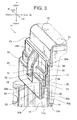
- Figs. 3 and 4 show the waterproof structure at a wall portion having the rotation support points 18, 24 as a representative example of the whole peripheral wall.
- a tiny passage 27 is formed between facing walls (later-described mating walls) of the waterproof structure portions at the main body side 20 and at the cover side 26 ( Fig. 5B shows schematically the tiny passage 27 indicating a water invasion direction).
- Fig. 5B shows schematically the tiny passage 27 indicating a water invasion direction.
- a mating wall at the main body side 28 is formed on the waterproof structure portion at the main body side 20.
- a mating wall at the cover side 29 is formed on the waterproof structure portion at the cover side 26.
- the mating wall at the main body side 28 and the mating wall at the cover side 29 face each other when the main body side 20 and at the cover side 26 are overlapped with each other. Walls as components of the mating wall at the main body side 28 and the mating wall at the cover side 29 are described below.
- the waterproof structure portion at the main body side 20 is provided on an upper end of the peripheral wall 17 for waterproofing as described above, and includes: a first waterproof portion 30 as an entrance side of the tiny passage 27; a second waterproof portion 31 as an intermediate portion of the tiny passage 27; and a third waterproof portion 32 as an exit side of the tiny passage 27 (in the tiny passage 27, a first water invasion portion from an outside is defined as an entrance).
- a first waterproof portion 30 as an entrance side of the tiny passage 27
- a second waterproof portion 31 as an intermediate portion of the tiny passage 27
- a third waterproof portion 32 as an exit side of the tiny passage 27 (in the tiny passage 27, a first water invasion portion from an outside is defined as an entrance).
- the third waterproof portion 32 is disposed at an upper end of the peripheral wall 17.
- the third waterproof portion 32 is formed with the same thickness as the peripheral wall 17 (An outer wall 17a and an inner wall 17b defining the thickness of the peripheral wall 17 are formed along the upper-lower direction).
- the third waterproof portion 32 has an upper wall 32a conforming to an upper end wall of the peripheral wall 17. This upper wall 32a is a component of the mating wall at the main body side 28. Further, an outer wall 32b continued to the upper wall 32a and perpendicular to the upper wall 32a is also a component of the mating wall at the main body side 28.
- the outer wall 32b is formed parallel to the inner wall 17b of the peripheral wall 17.
- the upper wall 32a has a small chamfered portion 32c at a portion continued to the inner wall 17b.
- the second waterproof portion 31 is arranged under the third waterproof portion 32.
- the second waterproof portion 31 has a wall which is substantially twice as thick as the third waterproof portion 32 (substantially twice as thick is one example).
- the second waterproof portion 31 is projected more outward than the third waterproof portion 32 because the second waterproof portion 31 is thicker than the third waterproof portion 32.
- An upper wall 31a of the second waterproof portion 31 is continued to the outer wall 32b of the third waterproof portion 32, and perpendicular to the outer wall 32b. Further, the upper wall 31a is formed parallel to the upper wall 32a of the third waterproof portion 32.
- the upper wall 31a is a component of the mating wall at the main body side 28.
- An outer wall 31b which is continued to and perpendicular to the upper wall 31a is formed longer than the outer wall 32b of the third waterproof portion 32.
- the outer wall 31b is formed parallel to the inner wall 17b of the peripheral wall 17.
- the outer wall 31b is a component of the mating wall at the main body side 28.
- a projection-shaped rotation support point 18 projected outward from the outer wall 31b is provided on a predetermined position of the outer wall 31b.
- the first waterproof portion 30 is arranged under the second waterproof portion 31.
- the first waterproof portion 30 is projected further outward than the second waterproof portion 31.
- An upper wall 30a of the first waterproof portion 30 is continued to and perpendicular to the outer wall 31b of the second waterproof portion 31. Further, the upper wall 30a is formed parallel to the upper wall 31a of the second waterproof portion 31.
- the upper wall 30a is formed longer than the upper wall 31a of the second waterproof portion 31.
- the upper wall 30a is a component of the mating wall at the main body side 28.
- An outer wall 30b continued to the upper wall 30a is not parallel to the inner wall 17b of the peripheral wall 17, but sloped.
- the outer wall 30b is a tapered wall so as to gradually decrease a distance to the inner wall 17b as the outer wall 30b extends downward.
- a blind passage 30c (corresponding to a second blind passage in claims) continued to the outer wall 17a of the peripheral wall 17 is formed in between the tapered outer wall 30b and the outer wall 17a.
- the blind passage 30c is formed so that a lower side is open and an upper side is dead end, and has a desired sized space.
- the blind passage 30c includes: an inner wall 30d conforming to the outer wall 17a of the peripheral wall 17; an outer wall 30e parallel to the inner wall 30d; and a backside wall 30f parallel to the upper wall 30a in an inside of the blind passage 30c.
- the blind passage 30c has a larger space than later-described other blind passage 35a, 33b (a larger amount of cleaning water enters the blind passage 30c).
- the mating wall at the main body side 28 is formed in a terraced shape, namely, in a maze shape. Namely, the mating wall at the main body side 28 is formed in a shape so as to prevent water from entering.
- the waterproof structure portion at the cover side 26 is provided on a lower end of the cover peripheral wall 23 to waterproof as described above, and includes: a first waterproof portion 33 as an entrance side of the tiny passage 27; a second waterproof portion 34 as a middle of the tiny passage 27; and a third waterproof portion 35 as an exit side of the tiny passage 27, and is formed in substantially a skirt shape opening outward.
- the first waterproof portion 33 is arranged corresponding to the first waterproof portion 30 of the waterproof structure portion at the main body side 20.
- the second waterproof portion 34 is arranged corresponding to the second waterproof portion 31 of the waterproof structure portion at the main body side 20.
- the third waterproof portion 35 is arranged corresponding to the third waterproof portion 32 of the waterproof structure portion at the main body side 20. We will explain sequentially from the third waterproof portion 35.
- the third waterproof portion 35 includes a blind passage 35a opened at a wall facing the upper wall 32a of the third waterproof portion 32 of the waterproof structure portion at the main body side 20 (a wall as a component of the mating wall at the cover side 29).
- the blind passage 35a is formed so that a lower side is open and an upper side is dead end, and has a desired sized space.
- the blind passage 35a includes: an inner wall 35b; an outer wall 35c parallel to the inner wall 35b; and a backside wall 35d connecting the inner wall 35b with the outer wall 35c.
- the inner wall 35b is arranged just over the inner wall 17b of the peripheral wall 17of the box main body 14.
- the blind passage 35a is formed so that the inner wall 35b is arranged at a lower end of the cover peripheral wall 23.
- the exit standards 36, 37 are set so as to narrow the exit of the tiny passage 27 as small as possible to prevent water from running out via the exit. (As the exit standard 36 is positioned more inside of the box main body 14 than the exit standard 37, the width of the exit becomes wider, and water runs out more easily via the tiny passage 27.)
- the third waterproof portion 35 includes a wall-shaped portion 35e continued to the blind passage 35a and extended downward and straight.
- This wall-shaped portion 35e includes an inner wall 35f facing the outer wall 32b of the third waterproof portion 32 of the waterproof structure portion at the main body side 20.
- the inner wall 35f is a component of the mating wall at the cover side 29.
- the inner wall 35f includes a small chamfered portion 35g at a portion continued to the second waterproof portion 34. (The chamfered portion 35g is also a component of the mating wall at the cover side 29.)
- the second waterproof portion 34 is arranged under the third waterproof portion 35.
- the second waterproof portion 34 is a wall-shaped portion having a lower wall 34a facing the upper wall 31a of the second waterproof portion 31 of the waterproof structure portion at the main body side 20, and an inner wall 34b facing the outer wall 31b.
- the lower wall 34a is continued to the chamfered portion 35g of the third waterproof portion 35, and the inner wall 34b is continued to the lower wall 34a at this opposite side.
- the inner wall 34b is formed perpendicular to the lower wall 34a, and extended downward and straight.
- This inner wall 34b includes a small chamfered portion 34c at a portion continued to the first waterproof portion 33.
- the lower wall 34a, the inner wall 34b, and the chamfered portion 34c are components of the mating wall at the cover side 29.
- the first waterproof portion 33 is arranged under the second waterproof portion 34.
- the first waterproof portion 33 includes a lower wall 33a facing the upper wall 30a of the first waterproof portion 30 of the waterproof structure portion at the main body side 20.
- the lower wall 33a is provided with a blind passage 33b opening at this position.
- the blind passage 33b is formed so that a lower side is open and an upper side is dead end, and has a desired sized space.
- the blind passage 33b includes: an inner wall 33c; an outer wall 33d parallel to the inner wall 33c; and a backside wall 33e connecting the inner wall 33c with the outer wall 33d.
- the inner wall 33c is formed perpendicular to the upper wall 30a of the first waterproof portion 30.
- the first waterproof portion 33 includes a wall-shaped portion 33f continued to the blind passage 33b and extended downward and straight.
- This wall-shaped portion 33f includes a tapered inner wall 33g.
- the inner wall 33g is formed so as to face the tapered outer wall 30b of the first waterproof portion 30 of the waterproof structure portion at the main body side 20, and so as to abut on and engage with the outer wall 30b when the upper cover 15 is going to be moved upward.
- the inner wall 33g is a component of the mating wall at the cover side 29.
- the first waterproof portion 33 includes: a lower wall 33h as the most bottom end of the upper cover 15; and a chamfered portion 33i continued to the lower wall 33h and the inner wall 33g other than the above described walls.
- the rotation support point 24 provided on the waterproof structure portion at the cover side 26 includes: a through-hole (not shown) allowing the projection-shaped rotation support point 18 of the waterproof structure portion at the main body side 20 to insert; and a pair of protection walls 24a disposed at both sides of the through-hole.
- the pair of protection walls 24a are formed in a rib shape, and extended in the upper-lower direction.
- the cavity of the functional component 12 is provided with the inner wall 12a.
- This inner wall 12a is arranged with a predetermined gap from the inner wall 17b of the peripheral wall 17 of the box main body 14.
- a tip 12b of the inner wall 12a is projected so as to be positioned at the base end side of the cover peripheral wall 23.
- the tip 12b of the inner wall 12a is projected so as to be positioned higher than the exit of the tiny passage 27.
- the inner wall 12a is formed as a component in order to prevent water from being splashed onto the electric component or the like (components disliking water) other than the waterproof structure portion at the main body side 20 and the waterproof structure portion at the cover side 26.
- the waterproof structure portion at the main body side 20 and the waterproof structure portion at the cover side 26 are enough to prevent water from being splashed onto the electric component or the like (components disliking water). To form the inner wall 12a is effective to improve certainty.
- the upper cover 15 includes the inner wall 38 extended so as to face the inner wall 17b of the peripheral wall 17 of the box main body 14.
- the inner wall 38 is formed so as to continue to a lower end of the cover peripheral wall 23.
- the inner wall 38 is provided on other than the wall on which the rotation support point 24 as a rotation center of the upper cover 15 exists. This reason is because the upper cover 15 is rotatable, in consideration of the rotation track, the inner wall 38 is provided on other than the above wall.
- the wall on which the rotation support point 24 exists is provided with the tapered portion 39 so that a tip of the tapered portion 39 is lower than the exit of the tiny passage 27.
- the tapered portion 39 slightly works as an inner wall.
- the cleaning water jetted toward the waterproof box 11 hits (the outer wall 17a of) the peripheral wall 17 of the box main body 14, and then the cleaning water moves upward along the peripheral wall 17.
- the cleaning water moving upward along the peripheral wall 17 enters the blind passage 30c of the waterproof structure portion at the main body side 20, thereby the force of the water is reduced.
- the blind passage 30c works as a buffer, and the cleaning water of which force is reduced falls down.
- the tiny passage 27 is formed in a maze shape having a plurality of steps (corners), the water is prevented from entering (passing) due to the maze shape.
- the water enters between the outer wall 32b and the inner wall 35f of the third waterproof portions 32, 35, because the travelling direction of the water is an extending direction of the outer wall 32b and the inner wall 35f, the water enters the blind passage 35a, and the force of the water is reduced.
- the blind passage 35a works as a buffer, and the water of which force is reduced falls down.
- the exit of the tiny passage 27 is formed as small as possible as described above, the water entering the blind passage 35a and of which force is reduced is hard to exit. If the water exits the exit of the tiny passage 27, this water falls down along the inner wall 17b of the peripheral wall 17, and is drained off from a not-shown drain outlet of the lower cover 16.
- Fig. 9 is a perspective view
- Fig. 10 is a sectional view
- Fig. 11 is an enlarged sectional view showing the third waterproof portion and the second waterproof portion of Fig. 10
- Fig. 12 is an enlarged sectional view showing the second waterproof portion and the first waterproof portion of Fig. 10
- Figs. 9 and 10 show a waterproof structure of a wall portion having the rotation support point as a representative example of the whole peripheral wall. Incidentally, only the waterproof structure portions at the main body side and at the cover side are different from the embodiment shown in Figs. 3 to 8 , and the other portions are the same (the same components are denoted by the same reference signs).
- the mating wall at the main body side 28 is formed on the waterproof structure portion at the main body side 20. Further, the mating wall at the cover side 29 is formed on the waterproof structure portion at the cover side 26. When the waterproof structure portions at the main body side 20 and at the cover side 26 are overlapped with each other, the mating walls at the main body side 28 and at the cover side 29 face each other. The tiny passage 27 is generated between them. Walls as components of the mating walls at the main body side 28 and at the cover side 29 will be described later.
- the waterproof structure portion at the main body side 20 is formed at the upper end portion of the peripheral wall 17 and works as a waterproof structure, and includes: a first waterproof portion 50 as an entrance side of the tiny passage 27; a second waterproof portion 51 as a middle of the tiny passage 27; and a third waterproof portion 52 as an exit side of the tiny passage 27.
- a first waterproof portion 50 as an entrance side of the tiny passage 27
- a second waterproof portion 51 as a middle of the tiny passage 27
- a third waterproof portion 52 as an exit side of the tiny passage 27.
- the third waterproof portion 52 is disposed at the upper end of the peripheral wall 17.
- the third waterproof portion 52 is formed with the same thickness as the peripheral wall 17.
- the third waterproof portion 52 includes an upper wall 52a conforming to an upper end of the peripheral wall 17.
- This upper wall 52a is a component of the mating wall at the main body side 28.
- an outer wall 52b extending perpendicular to the upper wall 52a is also a component of the mating wall at the main body side 28.
- the outer wall 52b is formed parallel to the inner wall 17b of the peripheral wall 17.
- the upper wall 52a includes a small chamfered portion 52c at a portion continued to the inner wall 17b.
- the upper wall 52a also includes a chamfered portion 52d opposite to the chamfered portion 52c.
- a press-fit portion 52e projected outward is formed on the outer wall 52b.
- This press-fit portion 52e is a portion to generate a press-fit state.
- the press-fit portion 52e is formed by arranging a plurality of ribs each having substantially triangle section in the upper-lower direction (the number of ribs of the press-fit portion 52e is one example).
- the second waterproof portion 51 is arranged under the third waterproof portion 52.
- the second waterproof portion 51 has a wall which is substantially twice as thick as the third waterproof portion 52 (substantially twice as thick is one example).
- the second waterproof portion 51 is projected more outward than the third waterproof portion 52 because the second waterproof portion 51 is thicker than the third waterproof portion 52.
- An upper wall 51a of the second waterproof portion 51 is continued to the outer wall 52b of the third waterproof portion 52, and perpendicular to the outer wall 52b. Further, the upper wall 51a is formed parallel to the upper wall 52a of the third waterproof portion 52.
- the upper wall 51a is a component of the mating wall at the main body side 28.
- An outer wall 51b which is continued to and perpendicular to the upper wall 51a is formed longer than the outer wall 52b of the third waterproof portion 52.
- the outer wall 51b is formed parallel to the inner wall 17b of the peripheral wall 17.
- the outer wall 51b is a component of the mating wall at the main body side 28.
- a projection-shaped rotation support point 18 projected outward from the outer wall 51b is provided on a predetermined position of the outer wall 51b.
- the first waterproof portion 50 is arranged under the second waterproof portion 51.
- the first waterproof portion 50 is projected further outward than the second waterproof portion 51.
- a feature of the first waterproof portion 50 is to have a spring portion 50e elastically blocking an opening of a later-described blind passage 53b.
- An upper wall 50a of the first waterproof portion 50 is continued to and perpendicular to the outer wall 51b of the second waterproof portion 51. Further, the upper wall 50a is formed parallel to the upper wall 51a of the second waterproof portion 51.
- the upper wall 50a is formed longer than the upper wall 51a of the second waterproof portion 51.
- the upper wall 50a is a component of the mating wall at the main body side 28.
- the first waterproof portion 50 further includes a step-shaped lower wall 50d. For giving elasticity to the spring portion 50e, the first waterproof portion 50 is formed slim from the upper wall 50a to the lower wall 50d.
- the mating wall at the main body side 28 is formed in a terraced shape, namely, in a maze shape. Namely, the mating wall at the main body side 28 is formed in a shape so as to prevent water from entering.
- the waterproof structure portion at the cover side 26 is provided on a lower end of the cover peripheral wall 23 to waterproof, and includes: a first waterproof portion 53 as an entrance side of the tiny passage 27; a second waterproof portion 54 as a middle of the tiny passage 27; and a third waterproof portion 55 as an exit side of the tiny passage 27, and is formed in substantially a skirt shape opening outward.
- the first waterproof portion 53 is arranged corresponding to the first waterproof portion 50 of the waterproof structure portion at the main body side 20.
- the second waterproof portion 54 is arranged corresponding to the second waterproof portion 51 of the waterproof structure portion at the main body side 20.
- the third waterproof portion 55 is arranged corresponding to the third waterproof portion 52 of the waterproof structure portion at the main body side 20.
- the third waterproof portion 55 includes a blind passage 55a opened at a wall facing the upper wall 52a of the third waterproof portion 52 of the waterproof structure portion at the main body side 20 (a wall as a component of the mating wall at the cover side 29).
- the blind passage 55a is formed so that a lower side is open and an upper side is dead end, and has a desired sized space.
- the blind passage 55a includes: an inner wall 55b; an outer wall 55c parallel to the inner wall 55b; and a backside wall 55d connecting the inner wall 55b with the outer wall 55c.
- the inner wall 55b is arranged just over the inner wall 17b of the peripheral wall 17of the box main body 14.
- the blind passage 55a is formed so that the inner wall 55b is arranged at a lower end of the cover peripheral wall 23. Incidentally, an arrangement of the blind passage 55a and an exit position of the tiny passage 27 is the same as those of the 35a shown in Fig. 6 .
- the third waterproof portion 55 includes a wall-shaped portion 55e continued to the blind passage 55a and extended downward and straight.
- This wall-shaped portion 55e includes an inner wall 55f facing the outer wall 52b of the third waterproof portion 52 of the waterproof structure portion at the main body side 20.
- the inner wall 55f is a component of the mating wall at the cover side 29. Further, the inner wall 55f is also formed as a portion where the press-fit portion 52e of the third waterproof portion 52 becomes a press-fit state.
- the inner wall 55f includes a small chamfered portion 55g at a portion continued to the second waterproof portion 51. (The chamfered portion 55g is also a component of the mating wall at the cover side 29.)
- the second waterproof portion 54 is arranged under the third waterproof portion 55.
- the second waterproof portion 54 is a wall-shaped portion having a lower wall 54a facing the upper wall 51a of the second waterproof portion 51 of the waterproof structure portion at the main body side 20, and an inner wall 54b facing the outer wall 51b.
- the lower wall 54a is continued to the chamfered portion 55g of the third waterproof portion 55, and the inner wall 54b is continued to the lower wall 54a at this opposite side.
- the inner wall 54b is formed perpendicular to the lower wall 54a, and extended downward and straight.
- This inner wall 54b includes a relatively large chamfered portion 54c at a portion continued to the first waterproof portion 53.
- the lower wall 54a, the inner wall 54b, and the chamfered portion 54c are components of the mating wall at the cover side 29.
- the first waterproof portion 53 is arranged under the second waterproof portion 54.
- the first waterproof portion 53 includes a lower wall 53a facing the upper wall 50a of the first waterproof portion 50 of the waterproof structure portion at the main body side 20.
- the lower wall 53a is provided with a blind passage 53b opening at this position.
- the blind passage 53b is formed so that a lower side is open and an upper side is dead end, and has a desired sized space.
- the blind passage 53b includes: an inner wall 53c; an outer wall 53d parallel to the inner wall 53c; and a backside wall 53e connecting the inner wall 53c with the outer wall 53d.
- the inner wall 53c is formed perpendicular to the upper wall 50a of the first waterproof portion 50.
- Reference sign 53j denotes a seal portion. This seal portion 53j is arranged so as to be continued to the opening and the outer wall 53d. The seal portion 53j is formed in a projection shape.
- the first waterproof portion 53 includes a wall-shaped portion 53f continued to the blind passage 53b.
- This wall-shaped portion 53f includes an inner wall 53g.
- the inner wall 53g is formed so as to face the outer wall 50b of the first waterproof portion 50 of the waterproof structure portion at the main body side 20.
- the inner wall 33g is a component of the mating wall at the cover side 29.
- the first waterproof portion 53 includes a lower wall 53h as the most bottom end of the upper cover 15 other than the above described walls.
- the rotation support point 24 provided on the waterproof structure portion at the cover side 26 includes: a through-hole (not shown) allowing the projection-shaped rotation support point 18 of the waterproof structure portion at the main body side 20 to insert; and a pair of protection walls 24a disposed at both sides of the through-hole.
- the pair of protection walls 24a are formed in a rib shape, and extended in the upper-lower direction.
- the cleaning water jetted toward the waterproof box 11 hits (the outer wall 17a of) the peripheral wall 17 of the box main body 14, and then the cleaning water moves upward along the peripheral wall 17.
- the cleaning water moving upward along the peripheral wall 17 presses the lower wall 50d of the first waterproof portion 50 of the waterproof structure portion at the main body side 20, and the blind passage 53b is blocked by the first waterproof portion 50 working as the spring portion 50e (because the lower wall 50d is hitted by the high pressure cleaning water, the opening of the blind passage 53b is blocked, and the water is prevented from entering (passing) ahead of the entrance of the tiny passage 27).
- the third waterproof portion 52 includes the press-fit portion 52e, the water is prevented from entering (passing) due to the maze shape and the press-fit portion 52e.
- the water enters ahead of the press-fit portion 52e, the water enters the blind passage 55a, and the force of the water is reduced.
- the blind passage 55a works as a buffer, and the water of which force is reduced falls down.
- the exit of the tiny passage 27 is formed as small as possible. Therefore, the water entering the blind passage 55a and of which force is reduced is hard to exit. If the water exits the exit of the tiny passage 27, this water falls down along the inner wall 17b of the peripheral wall 17, and is drained off from a not-shown drain outlet of the lower cover 16.
Landscapes
- Engineering & Computer Science (AREA)
- Architecture (AREA)
- Civil Engineering (AREA)
- Structural Engineering (AREA)
- Mechanical Engineering (AREA)
- Casings For Electric Apparatus (AREA)
- Closures For Containers (AREA)
- Connection Or Junction Boxes (AREA)
Abstract
Description
- This invention relates to a waterproof box waterproofed by overlapping a waterproof structure portion of a box main body with a waterproof structure portion of a cover.
- An electrical junction box mounted on such as an engine room of a vehicle includes: a connecting components such as a wiring harness; an electronic components such as relay, fuse, or the like; and electric equipment such as an electric control unit. Therefore, when a vehicle runs in the rain, or when an engine room is washed under high pressure, it is necessary to prevent water from being splashed onto an inside of the electrical junction box. Therefore, the electrical junction box is made so as to be waterproofed by providing respectively waterproof structures to a box main body receiving the electric components and the like, and to a cover covering an upper opening of the box main body. The electrical junction box works as a waterproof box.
- Regarding the waterproof box, it is known that a type of waterproof box waterproofed by holding a packing between the waterproof structure portion of the box main body and the waterproof structure portion of the cover (for example, see
Patent Document 1 listed below), and that a type of waterproof box waterproofed by overlapping the waterproof structure portion of the box main body with the waterproof structure portion of the cover without using the packing (for example, seePatent Document 2 listed below). - In the type of waterproof box using the packing, a gap is filled with the packing held between both waterproof structure portions, thereby waterproof performance is increased. However, there is a problem that the number of components is increased by the packing, and the cost of the waterproof box is increased by the packing. Further, there is also a problem that man-hours for attaching the packing are needed. Therefore, in recent years, a packing-less type of waterproof box has been used.
- As the packing-less type of waterproof box, a waterproof box disclosed in the
Patent Document 2 includes: a box main body having an upper opening; and a cover covering the upper opening. This waterproof box is waterproofed by overlapping the waterproof structure portion of the box main body with the waterproof structure portion provided on a seam joint portion of the cover. Specifically, the waterproof structure portion at the box main body side includes a circular waterproof convex provided around a tip position of a peripheral wall of the box main body. The waterproof structure portion at the cover side includes a circular waterproof concave provided around a tip position of a peripheral wall of the cover. - According to the above configuration and the above structure, when the cover is disposed above the upper opening of the box main body, then moved downward straight, and the waterproof structure portions are overlapped with each other, the waterproof convex is inserted into the waterproof concave. Further, a U-shaped cover lock provided on the waterproof structure portion of the cover is caught by, and locked with a main body lock provided on the waterproof structure portion of the main body, thereby the box main body and the cover are in a locked state. The main body locks and the cover locks are arranged on at least two positions on left and right sides of the waterproof box (or front and rear sides). These two positions are separated from each other.
-
- Patent Document 1:
JP, A, 2001-72116 - Patent Document 2:
JP, A, H09-216648 - There is a problem below in the packing-less type waterproof box. Namely, when a water jet pressure of the high pressure washing is too high, the washing water jetted toward the waterproof box abuts on the peripheral wall of the waterproof box, and then is moved upward along the peripheral wall, and finally, is passed through a slight gap between the waterproof structure portions overlapped with each other. In this way, there is a problem that a part of water gets into an inside of the waterproof box.
- Incidentally, in a case of the
Patent Document 2, an inner wall is provided on an inside of the peripheral wall and on an inside of the waterproof structure portion. Therefore, even when the water gets into an inside of the waterproof box, the inner wall prevents the water from being splashed onto the electric components or the like. However, some of the well-known many waterproof boxes are unable to be provided with an inner wall (unable to be partially provided with an inner wall), and it is necessary to prepare an effective countermeasure on the waterproof structure portions of the box main body and the cover. - Recently, an aluminum electric wire may have been drawn into the waterproof box. The aluminum electric wire dislikes an attachment of the water to a connecting portion. Therefore, the waterproof box has an increased need for preventing the water from attaching.
- Further, there is also a problem below in the packing-less type waterproof box. Namely, when the locking condition between the main lock and the cover lock is released, it is necessary to respectively release the locking conditions at least two positions. So, there is a problem that it is a troublesome operation for an operator or a user. Further, there is a problem that for releasing the locking conditions respectively at two positions, and for removing the cover, a large space allowed to use both hands is needed to be secured above the waterproof box. Incidentally, needless to say, the maintenance of the waterproof performance should be taken care of, when these problems are solved.
- Accordingly, in view of the above condition, an object of the present invention is to provide a waterproof box able to improve waterproof performance. Further, another object is to provide a waterproof box able to improve operability and to save space.
- For attaining the object, according to the invention claimed in
claim 1, there is provided a waterproof box comprising: - a box main body having a peripheral wall and receiving components inside of the peripheral wall, the components being susceptive to moisture;
- a cover having a cover peripheral wall and covering an opening provided at an edge of the peripheral wall of the main body;
- a waterproof structure portion provided at the edge of the peripheral wall of the main body; and
- a waterproof structure portion provided at an edge of the cover peripheral wall of the cover,
- wherein the waterproof box is waterproofed by the waterproof structure portions of the main body and of the cover overlapped with each other, and
- wherein the waterproof structure portion of the main body includes a mating surface, the waterproof structure portion of the cover includes a mating surface adapted to be brought into contact with the mating surface of the main body, and blind passages are provided on the mating surface of the waterproof structure portion of the cover, the blind passages each having a space with a desired size, and the blind passages being provided at an intermediate position and/or a position near an entrance of a tiny passage defined by a gap between the mating surfaces of the main body and of the cover.
- According to the present invention having such an aspect, the tiny passage defined by the gap between the mating surfaces of the main body and of the cover is, in other words, the tiny passage of water. Therefore, by providing the blind passages on the intermediate position and/or the position near the entrance of the tiny passage, in particular, when the water pressure is high, the blind passage can work as a buffer. By providing the blind passage, the force of the water can be reduced. Even when the water passes an exit of the tiny passage, the force of the water is very small, and the water is prevented from being splashed onto the electric components or the like received in the box main body. Incidentally, the water passing through the exit of the tiny passage falls down, and is discharged through a drain outlet of an undercover assembled under the box main body.
- According to the invention claimed in
claim 2, there is provided the waterproof box as claimed inclaim 1,
wherein rotation support points for making the cover rotatable and detachable relative to the box main body are provided on the waterproof structure portions of the main body and of the cover. - According to the present invention having such an aspect, the cover becomes rotatable about the rotation support point. The cover can open or close the opening of the box main body by rotating the cover. The lock mechanisms in the box main body and the cover for locking the box main body and the cover with each other are only provided at positions opposite to positions on which the rotation support points are provided. Namely, the lock can be released at one point. According to the present invention, the cover can be detached by only one action with a single hand.
- According to the invention claimed in
claims 3 and 4, there is provided the waterproof box as claimed inclaim
wherein an entrance side of the tiny passage is disposed outward from an outer peripheral wall of the box main body, and
wherein a second blind passage having a space with a desired size is provided inside of the mating surface of the main body at the entrance side of the tiny passage, and continued to the outer peripheral wall. - According to the present invention having such an aspect, the cleaning water jetted toward the waterproof box hits the peripheral wall of the box main body, then moves upward along the peripheral wall, and enters the second blind passage. The force of the water entering the second blind passage is reduced. Further, according to the present invention, because the entrance of the tiny passage is disposed outward of the outer peripheral wall of the box main body, the water is prevented from entering.
- According to the invention claimed in
claims 5 and 6, there is provided the waterproof box as claimed inclaim
wherein a spring including the mating surface of the main body and elastically closing an opening of the blind passage is provided on the mating surface of the main body. - According to the present invention having such an aspect, the opening of the blind passage is elastically blocked by the spring. Thereby, a passage (invasion) of the water is restricted. If the water is passed against the elastic force of the spring, the force of the water is reduced by entering the blind passage.
- According to the invention claimed in claim 7, there is provided the waterproof box as claimed in any one of
claims 1 to 6,
wherein a press-fit portion for generating a press-fit state is provided on the tiny pass at a position nearer the exit of the tiny passage than the blind passage. - According to the present invention having such an aspect, because the press-fit state is generated by the press-fit portion, the passage (invasion) of the water is restricted.
- According to the invention claimed in
claim 1, by providing a blind passage in the middle of the tiny passage, an effect to reduce the force of the water moving upward the tiny passage is achieved. Therefore, according to the present invention, even if the water is passed through the exit of the tiny passage, the force of the water is reduced, thereby an effect to prevent the water from splashing onto the components received in the box main body is achieved. Further, according to the present invention, the waterproof performance can be higher than the conventional waterproof box. - According to the invention claimed in
claim 2, by providing a rotation support point, an effect to attach and detach the cover by one action with a single hand is achieved. Therefore, according to the present invention, an effect to increase the workability more than the conventional waterproof box is achieved. Further, it becomes unnecessary to keep a large space of both hands of a worker above the cover because of the one action with a single hand, thereby an effect to save space is achieved. - According to the invention claimed in
claims 3 and 4, by providing a second blind passage, an effect to reduce the force of the water moving upward along the peripheral wall of the box main body is achieved. Therefore, according to the present invention, an effect to further improve the waterproof performance is achieved. - According to the invention claimed in
claims 5 and 6, by providing a spring for elastically closing the opening of the blind passage, an effect to restrict the passage of the water and to further improve the waterproof performance is achieved. - According to the invention claimed in claim 7, by providing a press-fit portion, an effect to restrict the passage of the water and to further improve the waterproof performance is achieved.
-
- [
Fig. 1 ] A schematic view showing an installation example of an electrical junction box including a waterproof box according to the present invention. - [
Fig. 2 ] An exploded perspective view showing the electrical junction box. - [
Fig. 3 ] A partially sectional perspective view showing waterproof structure portions at a main body side and at a cover side. - [
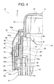
Fig. 4 ] A sectional view showing the waterproof structure portions at the main body side and at the cover side. - [
Fig. 5A ] A sectional view showing the waterproof structure portions at the main body side and at the cover side. - [
Fig. 5B ] A schematic view showing a tiny passage. - [
Fig. 6 ] An enlarged sectional view showing a third waterproof portion. - [
Fig. 7 ] An enlarged sectional view showing a second waterproof portion. - [
Fig. 8 ] An enlarged sectional view showing a first waterproof portion. - [
Fig. 9 ] A partially sectional perspective view showing another embodiment of the waterproof structure portions at the main body side and at the cover side. - [
Fig. 10 ] A sectional view showing another embodiment of the waterproof structure portions at the main body side and at the cover side. - [
Fig. 11 ] An enlarged sectional view showing the third and second waterproof portions ofFig. 10 . - [
Fig. 12 ] An enlarged sectional view showing the second and first waterproof portions ofFig. 10 . - Hereinafter, an example of an embodiment will be explained with reference to figures.
Fig. 1 is a schematic view showing an installation example of an electrical junction box including a waterproof box according to the present invention. Further,Fig. 2 is an exploded perspective view showing the electrical junction box. Further,Figs. 3 to 8 are various kinds of figures according to the waterproof box of the present invention. - In
Fig. 1 ,reference sign 1 denotes an electrical junction box (on vehicle electric components receiving device such as R/B: relay box, J/B: junction box, ECU or the like). Anelectrical junction box 1 is a relay box, but not limited to, and mounted on anengine room 3 of avehicle 2. In theengine room 3, abattery 5 is mounted next to an engine 4. Further, theelectrical junction box 1 is mounted next to this. Because theelectrical junction box 1 is mounted in theengine room 3, when thevehicle 2 runs in the rain, or when theengine room 3 is washed under high pressure, it is necessary to prevent water from being splashed onto electric components or the like (components disliking water) received in an inside of theelectrical junction box 1. - The
electrical junction box 1 explained below includes a waterproof box according to the present invention, and water is prevented from being splashed onto the electric components or the like received in an inside of theelectrical junction box 1 even if the water pressure of the high pressure cleaning is high such as 8 MPa to 12 Mpa. - In
Fig. 2 , theelectrical junction box 1 includes: a synthetic-resin-madewaterproof box 11; andfunctional components waterproof box 11. A not-shown wiring harness having, for example, aluminum electric wire is guided into thewaterproof box 11. Thefunctional components Fig. 2 .) A later-describedinner wall 12a is provided on the cavity of thefunctional component 12. - The
waterproof box 11 includes: a boxmain body 14 receiving thefunctional components main body 14; and alower cover 16 fitted into a lower portion of the boxmain body 14. - The present invention has some features in the box
main body 14 and theupper cover 15. One of these features is to have a waterproof structure having high waterproof performance despite packing-less. Further, another feature is that theupper cover 15 is rotatable with respect to the boxmain body 14, and detachable by one action with a single hand. Hereinafter, the boxmain body 14 and theupper cover 15 will be explained including these features. - The box
main body 14 has aperipheral wall 17. Theperipheral wall 17 is formed in a frame shape. Theperipheral wall 17 is formed in a shape shown inFig. 2 by continuing a plurality of walls. Here, an arrow P is defined as an upper-lower direction, an arrow Q is defined as a front-rear direction, and an arrow R is defined as a left-right direction (here, they are defined so as not to match the front-rear direction and the left-right direction of the engine room 3). A rotation support point 18 (seeFig. 3 ) for making theupper cover 15 rotatable and detachable is provided on an outer wall at a rear side of theperipheral wall 17. Further, a main-body lock 19 for making theupper cover 15 in a locked state is provided on an outer wall at a front side of theperipheral wall 17. - In the box
main body 14, theupper cover 15 is rotatable about therotation support point 18, and the main-body lock 19 makes theupper cover 15 in a locked state. Further, theupper cover 15 is easily detached by releasing the locked state and at the same time by rotating theupper cover 15 while lifting. - A waterproof structure portion at the
main body side 20 for waterproofing is provided around a periphery of an upper end of theperipheral wall 17. Further, afitting portion 21 for fitting thelower cover 16 is provided around a periphery of a lower end of theperipheral wall 17. Incidentally, a commonly-known structure is used in thefitting portion 21, and an explanation here is omitted. - The
upper cover 15 is formed so as to match with a shape of the boxmain body 14, and includes: aceiling wall 22 as a top portion of thewaterproof box 11; and a coverperipheral wall 23 extended downward from a peripheral edge of theceiling wall 22. A rear wall of the coverperipheral wall 23 is provided with a rotation support point 24 (seeFig. 3 ) as a rotation center of theupper cover 15 together with the rotation support point 18 (seeFig. 3 ) of the boxmain body 14. Further, acover lock 25 for hooking on the main-body lock 19 of the boxmain body 14 and being locked is provided on an outer wall at a front side of the coverperipheral wall 23. A waterproof structure portion at thecover side 26 for waterproofing is provided around a periphery of a lower end of the coverperipheral wall 23. - A commonly-known structure is used in the
lower cover 16, and an explanation in detail is omitted. - The waterproof structure portions at the
main body side 20 and at thecover side 26 will be explained in detail with reference toFigs. 3 to 8 .Figs. 3 and4 show the waterproof structure at a wall portion having the rotation support points 18, 24 as a representative example of the whole peripheral wall. - As shown in
Figs. 3 and4 , when theupper cover 15 is rotated with respect to the boxmain body 14, and then made in a locked state, the waterproof structure portions at themain body side 20 and at thecover side 26 are overlapped with each other. - Incidentally, for rotating the
upper cover 15, structurally, it is necessary to consider a rotation trace, however, it is impossible to overlap them without a gap across the whole periphery. Therefore, atiny passage 27 is formed between facing walls (later-described mating walls) of the waterproof structure portions at themain body side 20 and at the cover side 26 (Fig. 5B shows schematically thetiny passage 27 indicating a water invasion direction). Incidentally, it is an object of the waterproof structure of thewaterproof box 11 to prevent the water invasion within a range of thetiny passage 27, and to reduce dramatically the force of the invading water. - A mating wall at the
main body side 28 is formed on the waterproof structure portion at themain body side 20. A mating wall at thecover side 29 is formed on the waterproof structure portion at thecover side 26. The mating wall at themain body side 28 and the mating wall at thecover side 29 face each other when themain body side 20 and at thecover side 26 are overlapped with each other. Walls as components of the mating wall at themain body side 28 and the mating wall at thecover side 29 are described below. - As shown in
Figs. 3 to 8 , the waterproof structure portion at themain body side 20 is provided on an upper end of theperipheral wall 17 for waterproofing as described above, and includes: a firstwaterproof portion 30 as an entrance side of thetiny passage 27; a secondwaterproof portion 31 as an intermediate portion of thetiny passage 27; and a thirdwaterproof portion 32 as an exit side of the tiny passage 27 (in thetiny passage 27, a first water invasion portion from an outside is defined as an entrance). We will explain sequentially from the thirdwaterproof portion 32. - The third
waterproof portion 32 is disposed at an upper end of theperipheral wall 17. The thirdwaterproof portion 32 is formed with the same thickness as the peripheral wall 17 (Anouter wall 17a and aninner wall 17b defining the thickness of theperipheral wall 17 are formed along the upper-lower direction). The thirdwaterproof portion 32 has anupper wall 32a conforming to an upper end wall of theperipheral wall 17. Thisupper wall 32a is a component of the mating wall at themain body side 28. Further, anouter wall 32b continued to theupper wall 32a and perpendicular to theupper wall 32a is also a component of the mating wall at themain body side 28. Theouter wall 32b is formed parallel to theinner wall 17b of theperipheral wall 17. Theupper wall 32a has a small chamferedportion 32c at a portion continued to theinner wall 17b. - The second
waterproof portion 31 is arranged under the thirdwaterproof portion 32. The secondwaterproof portion 31 has a wall which is substantially twice as thick as the third waterproof portion 32 (substantially twice as thick is one example). The secondwaterproof portion 31 is projected more outward than the thirdwaterproof portion 32 because the secondwaterproof portion 31 is thicker than the thirdwaterproof portion 32. Anupper wall 31a of the secondwaterproof portion 31 is continued to theouter wall 32b of the thirdwaterproof portion 32, and perpendicular to theouter wall 32b. Further, theupper wall 31a is formed parallel to theupper wall 32a of the thirdwaterproof portion 32. Theupper wall 31a is a component of the mating wall at themain body side 28. Anouter wall 31b which is continued to and perpendicular to theupper wall 31a is formed longer than theouter wall 32b of the thirdwaterproof portion 32. Theouter wall 31b is formed parallel to theinner wall 17b of theperipheral wall 17. Theouter wall 31b is a component of the mating wall at themain body side 28. A projection-shapedrotation support point 18 projected outward from theouter wall 31b is provided on a predetermined position of theouter wall 31b. - The first
waterproof portion 30 is arranged under the secondwaterproof portion 31. The firstwaterproof portion 30 is projected further outward than the secondwaterproof portion 31. Anupper wall 30a of the firstwaterproof portion 30 is continued to and perpendicular to theouter wall 31b of the secondwaterproof portion 31. Further, theupper wall 30a is formed parallel to theupper wall 31a of the secondwaterproof portion 31. Theupper wall 30a is formed longer than theupper wall 31a of the secondwaterproof portion 31. Theupper wall 30a is a component of the mating wall at themain body side 28. Anouter wall 30b continued to theupper wall 30a is not parallel to theinner wall 17b of theperipheral wall 17, but sloped. Specifically, theouter wall 30b is a tapered wall so as to gradually decrease a distance to theinner wall 17b as theouter wall 30b extends downward. Ablind passage 30c (corresponding to a second blind passage in claims) continued to theouter wall 17a of theperipheral wall 17 is formed in between the taperedouter wall 30b and theouter wall 17a. - The
blind passage 30c is formed so that a lower side is open and an upper side is dead end, and has a desired sized space. Theblind passage 30c includes: aninner wall 30d conforming to theouter wall 17a of theperipheral wall 17; anouter wall 30e parallel to theinner wall 30d; and abackside wall 30f parallel to theupper wall 30a in an inside of theblind passage 30c. Theblind passage 30c has a larger space than later-described otherblind passage blind passage 30c). - When seeing from the
upper wall 32a of the thirdwaterproof portion 32 to the taperedouter wall 30b of the firstwaterproof portion 30 as components of the mating wall at themain body side 28 from a view of a section of the waterproof structure portion at themain body side 20, the mating wall at themain body side 28 is formed in a terraced shape, namely, in a maze shape. Namely, the mating wall at themain body side 28 is formed in a shape so as to prevent water from entering. - In contrast, the waterproof structure portion at the
cover side 26 is provided on a lower end of the coverperipheral wall 23 to waterproof as described above, and includes: a firstwaterproof portion 33 as an entrance side of thetiny passage 27; a secondwaterproof portion 34 as a middle of thetiny passage 27; and a thirdwaterproof portion 35 as an exit side of thetiny passage 27, and is formed in substantially a skirt shape opening outward. The firstwaterproof portion 33 is arranged corresponding to the firstwaterproof portion 30 of the waterproof structure portion at themain body side 20. Further, the secondwaterproof portion 34 is arranged corresponding to the secondwaterproof portion 31 of the waterproof structure portion at themain body side 20. Further, the thirdwaterproof portion 35 is arranged corresponding to the thirdwaterproof portion 32 of the waterproof structure portion at themain body side 20. We will explain sequentially from the thirdwaterproof portion 35. - The third
waterproof portion 35 includes ablind passage 35a opened at a wall facing theupper wall 32a of the thirdwaterproof portion 32 of the waterproof structure portion at the main body side 20 (a wall as a component of the mating wall at the cover side 29). Theblind passage 35a is formed so that a lower side is open and an upper side is dead end, and has a desired sized space. Theblind passage 35a includes: aninner wall 35b; anouter wall 35c parallel to theinner wall 35b; and abackside wall 35d connecting theinner wall 35b with theouter wall 35c. Theinner wall 35b is arranged just over theinner wall 17b of the peripheral wall 17of the boxmain body 14. Theblind passage 35a is formed so that theinner wall 35b is arranged at a lower end of the coverperipheral wall 23. - Regarding an arrangement of the
blind passage 35a and an exit position of thetiny passage 27, when an intersection point between an opening of theblind passage 35a and theinner wall 35b is set as anexit standard 36, and an intersection point between theinner wall 17b of theperipheral wall 17 and theupper wall 32a of the thirdwaterproof portion 32 is set as anexit standard 37, theseexit standards exit standards tiny passage 27 as small as possible to prevent water from running out via the exit. (As theexit standard 36 is positioned more inside of the boxmain body 14 than theexit standard 37, the width of the exit becomes wider, and water runs out more easily via thetiny passage 27.) - The third
waterproof portion 35 includes a wall-shapedportion 35e continued to theblind passage 35a and extended downward and straight. This wall-shapedportion 35e includes aninner wall 35f facing theouter wall 32b of the thirdwaterproof portion 32 of the waterproof structure portion at themain body side 20. Theinner wall 35f is a component of the mating wall at thecover side 29. Theinner wall 35f includes a small chamferedportion 35g at a portion continued to the secondwaterproof portion 34. (The chamferedportion 35g is also a component of the mating wall at thecover side 29.) - The second
waterproof portion 34 is arranged under the thirdwaterproof portion 35. The secondwaterproof portion 34 is a wall-shaped portion having alower wall 34a facing theupper wall 31a of the secondwaterproof portion 31 of the waterproof structure portion at themain body side 20, and aninner wall 34b facing theouter wall 31b. Thelower wall 34a is continued to the chamferedportion 35g of the thirdwaterproof portion 35, and theinner wall 34b is continued to thelower wall 34a at this opposite side. Theinner wall 34b is formed perpendicular to thelower wall 34a, and extended downward and straight. Thisinner wall 34b includes a small chamferedportion 34c at a portion continued to the firstwaterproof portion 33. Thelower wall 34a, theinner wall 34b, and the chamferedportion 34c are components of the mating wall at thecover side 29. - The first
waterproof portion 33 is arranged under the secondwaterproof portion 34. The firstwaterproof portion 33 includes alower wall 33a facing theupper wall 30a of the firstwaterproof portion 30 of the waterproof structure portion at themain body side 20. Thelower wall 33a is provided with ablind passage 33b opening at this position. Theblind passage 33b is formed so that a lower side is open and an upper side is dead end, and has a desired sized space. Theblind passage 33b includes: aninner wall 33c; anouter wall 33d parallel to theinner wall 33c; and abackside wall 33e connecting theinner wall 33c with theouter wall 33d. Theinner wall 33c is formed perpendicular to theupper wall 30a of the firstwaterproof portion 30. - The first
waterproof portion 33 includes a wall-shapedportion 33f continued to theblind passage 33b and extended downward and straight. This wall-shapedportion 33f includes a taperedinner wall 33g. Theinner wall 33g is formed so as to face the taperedouter wall 30b of the firstwaterproof portion 30 of the waterproof structure portion at themain body side 20, and so as to abut on and engage with theouter wall 30b when theupper cover 15 is going to be moved upward. Theinner wall 33g is a component of the mating wall at thecover side 29. - The first
waterproof portion 33 includes: alower wall 33h as the most bottom end of theupper cover 15; and a chamferedportion 33i continued to thelower wall 33h and theinner wall 33g other than the above described walls. - The
rotation support point 24 provided on the waterproof structure portion at thecover side 26 includes: a through-hole (not shown) allowing the projection-shapedrotation support point 18 of the waterproof structure portion at themain body side 20 to insert; and a pair ofprotection walls 24a disposed at both sides of the through-hole. The pair ofprotection walls 24a are formed in a rib shape, and extended in the upper-lower direction. - Return to
Fig. 2 , the cavity of thefunctional component 12 is provided with theinner wall 12a. Thisinner wall 12a is arranged with a predetermined gap from theinner wall 17b of theperipheral wall 17 of the boxmain body 14. Atip 12b of theinner wall 12a is projected so as to be positioned at the base end side of the coverperipheral wall 23. Thetip 12b of theinner wall 12a is projected so as to be positioned higher than the exit of thetiny passage 27. Theinner wall 12a is formed as a component in order to prevent water from being splashed onto the electric component or the like (components disliking water) other than the waterproof structure portion at themain body side 20 and the waterproof structure portion at thecover side 26. - The waterproof structure portion at the
main body side 20 and the waterproof structure portion at thecover side 26 are enough to prevent water from being splashed onto the electric component or the like (components disliking water). To form theinner wall 12a is effective to improve certainty. - As shown in
Fig. 4 , theupper cover 15 includes theinner wall 38 extended so as to face theinner wall 17b of theperipheral wall 17 of the boxmain body 14. Theinner wall 38 is formed so as to continue to a lower end of the coverperipheral wall 23. Theinner wall 38 is provided on other than the wall on which therotation support point 24 as a rotation center of theupper cover 15 exists. This reason is because theupper cover 15 is rotatable, in consideration of the rotation track, theinner wall 38 is provided on other than the above wall. The wall on which therotation support point 24 exists is provided with the taperedportion 39 so that a tip of the taperedportion 39 is lower than the exit of thetiny passage 27. The taperedportion 39 slightly works as an inner wall. - In the above configuration and the above structure, while the
upper cover 15 is held by a single hand, when therotation support point 24 of theupper cover 15 is inserted into therotation support point 18 of the boxmain body 14, and theupper cover 15 is rotated about therotation support point 18 and therotation support point 24, thecover lock 25 of theupper cover 15 is caught by the main-body lock 19 of the boxmain body 14, and locked (a locked state is generated). When the upper opening of the boxmain body 14 is covered by theupper cover 15, and the waterproof structure portion at themain body side 20 is overlapped with the waterproof structure portion at thecover side 26, a waterproof structure is completed as shown inFigs. 4 and5 . When the waterproof structure portion at themain body side 20 and the waterproof structure portion at thecover side 26 are overlapped with each other, the mating wall at themain body side 28 and the mating wall at thecover side 29 face each other. - When the high pressure cleaning is done, the cleaning water jetted toward the
waterproof box 11 hits (theouter wall 17a of) theperipheral wall 17 of the boxmain body 14, and then the cleaning water moves upward along theperipheral wall 17. The cleaning water moving upward along theperipheral wall 17 enters theblind passage 30c of the waterproof structure portion at themain body side 20, thereby the force of the water is reduced. Theblind passage 30c works as a buffer, and the cleaning water of which force is reduced falls down. - Because an entrance of the
tiny passage 27 is disposed away from theouter wall 17a of theperipheral wall 17 of the boxmain body 14, further, because the force of most of the water is reduced, the amount of the water hitting the entrance of thetiny passage 27 becomes little, and the water is prevented from entering (water is prevented from entering unless the cleaning water hits the entrance of thetiny passage 27 pinpoint hitting). - When the cleaning water hits the
lower wall 33h of the firstwaterproof portion 33 of the upper cover 15 (thelower wall 33h as the lowest end of the upper cover 15), and theupper cover 15 is moved in an arrow S direction, namely, theupper cover 15 is blown up, the taperedouter wall 30b and the taperedinner wall 33g of the firstwaterproof portions tiny passage 27 is blocked. Thereby, the water is prevented from entering (passing). - If the water enters before the tapered
outer wall 30b and the taperedinner wall 33g are engaged with each other, because a travelling direction of the water is an extending direction of theouter wall 30b and theinner wall 33g, the water enters theblind passage 33b, and the force of the water is reduced. - Further, if the water enters ahead of the
blind passage 33b, because thetiny passage 27 is formed in a maze shape having a plurality of steps (corners), the water is prevented from entering (passing) due to the maze shape. - Further, if the water enters between the
outer wall 32b and theinner wall 35f of the thirdwaterproof portions outer wall 32b and theinner wall 35f, the water enters theblind passage 35a, and the force of the water is reduced. Theblind passage 35a works as a buffer, and the water of which force is reduced falls down. - Because the exit of the
tiny passage 27 is formed as small as possible as described above, the water entering theblind passage 35a and of which force is reduced is hard to exit. If the water exits the exit of thetiny passage 27, this water falls down along theinner wall 17b of theperipheral wall 17, and is drained off from a not-shown drain outlet of thelower cover 16. - Next, another embodiment of the waterproof structures at the main body side and the cover side will be explained with reference to
Figs. 9 to 12 .Fig. 9 is a perspective view, andFig. 10 is a sectional view. Further,Fig. 11 is an enlarged sectional view showing the third waterproof portion and the second waterproof portion ofFig. 10 , andFig. 12 is an enlarged sectional view showing the second waterproof portion and the first waterproof portion ofFig. 10 .Figs. 9 and10 show a waterproof structure of a wall portion having the rotation support point as a representative example of the whole peripheral wall. Incidentally, only the waterproof structure portions at the main body side and at the cover side are different from the embodiment shown inFigs. 3 to 8 , and the other portions are the same (the same components are denoted by the same reference signs). - As shown in
Figs. 9 and10 , when theupper cover 15 is rotated with respect to the boxmain body 14, and they are in a locked state, the waterproof structure portions at themain body side 20 and at thecover side 26 are overlapped with each other. - The mating wall at the
main body side 28 is formed on the waterproof structure portion at themain body side 20. Further, the mating wall at thecover side 29 is formed on the waterproof structure portion at thecover side 26. When the waterproof structure portions at themain body side 20 and at thecover side 26 are overlapped with each other, the mating walls at themain body side 28 and at thecover side 29 face each other. Thetiny passage 27 is generated between them. Walls as components of the mating walls at themain body side 28 and at thecover side 29 will be described later. - In
Figs. 9 to 12 , the waterproof structure portion at themain body side 20 is formed at the upper end portion of theperipheral wall 17 and works as a waterproof structure, and includes: a firstwaterproof portion 50 as an entrance side of thetiny passage 27; a secondwaterproof portion 51 as a middle of thetiny passage 27; and a thirdwaterproof portion 52 as an exit side of thetiny passage 27. Hereinafter, we will sequentially explain from the thirdwaterproof portion 52. - The third
waterproof portion 52 is disposed at the upper end of theperipheral wall 17. The thirdwaterproof portion 52 is formed with the same thickness as theperipheral wall 17. The thirdwaterproof portion 52 includes anupper wall 52a conforming to an upper end of theperipheral wall 17. Thisupper wall 52a is a component of the mating wall at themain body side 28. Further, anouter wall 52b extending perpendicular to theupper wall 52a is also a component of the mating wall at themain body side 28. Theouter wall 52b is formed parallel to theinner wall 17b of theperipheral wall 17. Theupper wall 52a includes a small chamferedportion 52c at a portion continued to theinner wall 17b. Further, theupper wall 52a also includes a chamferedportion 52d opposite to the chamferedportion 52c. A press-fit portion 52e projected outward is formed on theouter wall 52b. This press-fit portion 52e is a portion to generate a press-fit state. In this embodiment, the press-fit portion 52e is formed by arranging a plurality of ribs each having substantially triangle section in the upper-lower direction (the number of ribs of the press-fit portion 52e is one example). - The second
waterproof portion 51 is arranged under the thirdwaterproof portion 52. The secondwaterproof portion 51 has a wall which is substantially twice as thick as the third waterproof portion 52 (substantially twice as thick is one example). The secondwaterproof portion 51 is projected more outward than the thirdwaterproof portion 52 because the secondwaterproof portion 51 is thicker than the thirdwaterproof portion 52. Anupper wall 51a of the secondwaterproof portion 51 is continued to theouter wall 52b of the thirdwaterproof portion 52, and perpendicular to theouter wall 52b. Further, theupper wall 51a is formed parallel to theupper wall 52a of the thirdwaterproof portion 52. Theupper wall 51a is a component of the mating wall at themain body side 28. Anouter wall 51b which is continued to and perpendicular to theupper wall 51a is formed longer than theouter wall 52b of the thirdwaterproof portion 52. Theouter wall 51b is formed parallel to theinner wall 17b of theperipheral wall 17. Theouter wall 51b is a component of the mating wall at themain body side 28. A projection-shapedrotation support point 18 projected outward from theouter wall 51b is provided on a predetermined position of theouter wall 51b. - The first
waterproof portion 50 is arranged under the secondwaterproof portion 51. The firstwaterproof portion 50 is projected further outward than the secondwaterproof portion 51. A feature of the firstwaterproof portion 50 is to have aspring portion 50e elastically blocking an opening of a later-describedblind passage 53b. Anupper wall 50a of the firstwaterproof portion 50 is continued to and perpendicular to theouter wall 51b of the secondwaterproof portion 51. Further, theupper wall 50a is formed parallel to theupper wall 51a of the secondwaterproof portion 51. Theupper wall 50a is formed longer than theupper wall 51a of the secondwaterproof portion 51. Theupper wall 50a is a component of the mating wall at themain body side 28. Anouter wall 50b continued to theupper wall 50a via a chamferedportion 50c is parallel to theinner wall 17b of theperipheral wall 17, and formed short in the upper-lower direction. The firstwaterproof portion 50 further includes a step-shapedlower wall 50d. For giving elasticity to thespring portion 50e, the firstwaterproof portion 50 is formed slim from theupper wall 50a to thelower wall 50d. - When seeing from the
upper wall 52a of the thirdwaterproof portion 52 to theouter wall 50b of the firstwaterproof portion 50 as components of the mating wall at themain body side 28 from a view of a section of the waterproof structure portion at themain body side 20, the mating wall at themain body side 28 is formed in a terraced shape, namely, in a maze shape. Namely, the mating wall at themain body side 28 is formed in a shape so as to prevent water from entering. - In contrast, the waterproof structure portion at the
cover side 26 is provided on a lower end of the coverperipheral wall 23 to waterproof, and includes: a firstwaterproof portion 53 as an entrance side of thetiny passage 27; a secondwaterproof portion 54 as a middle of thetiny passage 27; and a thirdwaterproof portion 55 as an exit side of thetiny passage 27, and is formed in substantially a skirt shape opening outward. The firstwaterproof portion 53 is arranged corresponding to the firstwaterproof portion 50 of the waterproof structure portion at themain body side 20. Further, the secondwaterproof portion 54 is arranged corresponding to the secondwaterproof portion 51 of the waterproof structure portion at themain body side 20. Further, the thirdwaterproof portion 55 is arranged corresponding to the thirdwaterproof portion 52 of the waterproof structure portion at themain body side 20. Hereinafter, we will explain sequentially from the thirdwaterproof portion 55. - The third
waterproof portion 55 includes ablind passage 55a opened at a wall facing theupper wall 52a of the thirdwaterproof portion 52 of the waterproof structure portion at the main body side 20 (a wall as a component of the mating wall at the cover side 29). Theblind passage 55a is formed so that a lower side is open and an upper side is dead end, and has a desired sized space. Theblind passage 55a includes: aninner wall 55b; anouter wall 55c parallel to theinner wall 55b; and abackside wall 55d connecting theinner wall 55b with theouter wall 55c. Theinner wall 55b is arranged just over theinner wall 17b of the peripheral wall 17of the boxmain body 14. Theblind passage 55a is formed so that theinner wall 55b is arranged at a lower end of the coverperipheral wall 23. Incidentally, an arrangement of theblind passage 55a and an exit position of thetiny passage 27 is the same as those of the 35a shown inFig. 6 . - The third
waterproof portion 55 includes a wall-shapedportion 55e continued to theblind passage 55a and extended downward and straight. This wall-shapedportion 55e includes aninner wall 55f facing theouter wall 52b of the thirdwaterproof portion 52 of the waterproof structure portion at themain body side 20. Theinner wall 55f is a component of the mating wall at thecover side 29. Further, theinner wall 55f is also formed as a portion where the press-fit portion 52e of the thirdwaterproof portion 52 becomes a press-fit state. Theinner wall 55f includes a small chamferedportion 55g at a portion continued to the secondwaterproof portion 51. (The chamferedportion 55g is also a component of the mating wall at thecover side 29.) - The second
waterproof portion 54 is arranged under the thirdwaterproof portion 55. The secondwaterproof portion 54 is a wall-shaped portion having alower wall 54a facing theupper wall 51a of the secondwaterproof portion 51 of the waterproof structure portion at themain body side 20, and aninner wall 54b facing theouter wall 51b. Thelower wall 54a is continued to the chamferedportion 55g of the thirdwaterproof portion 55, and theinner wall 54b is continued to thelower wall 54a at this opposite side. Theinner wall 54b is formed perpendicular to thelower wall 54a, and extended downward and straight. Thisinner wall 54b includes a relatively large chamferedportion 54c at a portion continued to the firstwaterproof portion 53. Thelower wall 54a, theinner wall 54b, and the chamferedportion 54c are components of the mating wall at thecover side 29. - The first
waterproof portion 53 is arranged under the secondwaterproof portion 54. The firstwaterproof portion 53 includes alower wall 53a facing theupper wall 50a of the firstwaterproof portion 50 of the waterproof structure portion at themain body side 20. Thelower wall 53a is provided with ablind passage 53b opening at this position. Theblind passage 53b is formed so that a lower side is open and an upper side is dead end, and has a desired sized space. Theblind passage 53b includes: aninner wall 53c; anouter wall 53d parallel to theinner wall 53c; and abackside wall 53e connecting theinner wall 53c with theouter wall 53d. Theinner wall 53c is formed perpendicular to theupper wall 50a of the firstwaterproof portion 50. An opening of theblind passage 53b is elastically blocked by thespring portion 50e (first waterproof portion 50).Reference sign 53j denotes a seal portion. Thisseal portion 53j is arranged so as to be continued to the opening and theouter wall 53d. Theseal portion 53j is formed in a projection shape. - The first
waterproof portion 53 includes a wall-shapedportion 53f continued to theblind passage 53b. This wall-shapedportion 53f includes aninner wall 53g. Theinner wall 53g is formed so as to face theouter wall 50b of the firstwaterproof portion 50 of the waterproof structure portion at themain body side 20. Theinner wall 33g is a component of the mating wall at thecover side 29. The firstwaterproof portion 53 includes alower wall 53h as the most bottom end of theupper cover 15 other than the above described walls. - The
rotation support point 24 provided on the waterproof structure portion at thecover side 26 includes: a through-hole (not shown) allowing the projection-shapedrotation support point 18 of the waterproof structure portion at themain body side 20 to insert; and a pair ofprotection walls 24a disposed at both sides of the through-hole. The pair ofprotection walls 24a are formed in a rib shape, and extended in the upper-lower direction. - In the above configuration and the above structure, when the high pressure cleaning is done, the cleaning water jetted toward the
waterproof box 11 hits (theouter wall 17a of) theperipheral wall 17 of the boxmain body 14, and then the cleaning water moves upward along theperipheral wall 17. The cleaning water moving upward along theperipheral wall 17 presses thelower wall 50d of the firstwaterproof portion 50 of the waterproof structure portion at themain body side 20, and theblind passage 53b is blocked by the firstwaterproof portion 50 working as thespring portion 50e (because thelower wall 50d is hitted by the high pressure cleaning water, the opening of theblind passage 53b is blocked, and the water is prevented from entering (passing) ahead of the entrance of the tiny passage 27). - Because an entrance of the
tiny passage 27 is disposed away from theouter wall 17a of theperipheral wall 17 of the boxmain body 14, water is prevented from entering unless the cleaning water hits the entrance of thetiny passage 27 pinpoint hitting. - When the cleaning water hits the
lower wall 53h of the firstwaterproof portion 53 of the upper cover 15 (thelower wall 53h as the lowest end of the upper cover 15), and theupper cover 15 is moved in the arrow S direction, namely, theupper cover 15 is blown up, or even if the water enters, the water enters theblind passage 53b, and the force of the water is reduced (even if theupper cover 15 is blown up, the firstwaterproof portion 50 follows theupper cover 15, thereby the opening of theblind passage 53b is blocked and the water is prevented from entering (passing)). - Further, if the water enters ahead of the
blind passage 53b, because thetiny passage 27 is formed in a maze shape having a plurality of steps (corners), further, the thirdwaterproof portion 52 includes the press-fit portion 52e, the water is prevented from entering (passing) due to the maze shape and the press-fit portion 52e. - Further, if the water enters ahead of the press-
fit portion 52e, the water enters theblind passage 55a, and the force of the water is reduced. Theblind passage 55a works as a buffer, and the water of which force is reduced falls down. - The exit of the
tiny passage 27 is formed as small as possible. Therefore, the water entering theblind passage 55a and of which force is reduced is hard to exit. If the water exits the exit of thetiny passage 27, this water falls down along theinner wall 17b of theperipheral wall 17, and is drained off from a not-shown drain outlet of thelower cover 16. - As you can understand from the above explanation of the present invention with reference to
Figs. 1 to 12 , according to the present invention, an effect to increase the waterproof performance higher than the conventional waterproof box is achieved. Further, because theupper cover 15 can be attached and detached by one action with a single hand, effects to increase the workability more than the conventional waterproof box and to save more space than the conventional waterproof box are achieved. - Of course, this invention can be practiced in various ways within a scope of the present invention.
-
- 1
-
electrical junction box 1 - 2
- vehicle
- 3
- engine room
- 4
- engine
- 5
- battery
- 11
- waterproof box
- 12, 13
- functional component
- 14
- box main body
- 15
- upper cover (cover)
- 16
- lower cover
- 17
- peripheral wall
- 18
- rotation support point
- 19
- main-body lock
- 20
- waterproof structure portion at the main body side
- 21
- fitting portion
- 22
- ceiling wall
- 23
- cover peripheral wall
- 24
- rotation support point
- 25
- cover lock
- 26
- waterproof structure portion at the cover side
- 27
- tiny passage
- 28
- mating wall at the main body side
- 29
- mating wall at the cover side
- 30, 33
- first waterproof portion
- 31, 34
- second waterproof portion
- 32, 35
- third waterproof portion
- 36, 37
- exit standard
- 38
- inner wall
- 39
- tapered portion
Claims (7)
- A waterproof box comprising:a box main body having a peripheral wall and receiving components inside of the peripheral wall, the components being susceptive to moisture;a cover having a cover peripheral wall and covering an opening provided at an edge of the peripheral wall of the main body;a waterproof structure portion provided at the edge of the peripheral wall of the main body; anda waterproof structure portion provided at an edge of the cover peripheral wall of the cover,wherein the waterproof box is waterproofed by the waterproof structure portions of the main body and of the cover overlapped with each other, andwherein the waterproof structure portion of the main body includes a mating surface, the waterproof structure portion of the cover includes a mating surface adapted to be brought into contact with the mating surface of the main body, and blind passages are provided on the mating surface of the waterproof structure portion of the cover, the blind passages each having a space with a desired size, and the blind passages being provided at an intermediate position and/or a position near an entrance of a tiny passage defined by a gap between the mating surfaces of the main body and of the cover.
- The waterproof box as claimed in claim 1,
wherein rotation support points for making the cover rotatable and detachable relative to the box main body are provided on the waterproof structure portions of the main body and of the cover. - The waterproof box as claimed in claim 1,
wherein an entrance side of the tiny passage is disposed outward from an outer peripheral wall of the box main body, and
wherein a second blind passage having a space with a desired size is provided inside of the mating surface of the main body at the entrance side of the tiny passage, and continued to the outer peripheral wall. - The waterproof box as claimed in claim 2,
wherein an entrance side of the tiny passage is disposed outward from an outer peripheral wall of the box main body, and
wherein a second blind passage having a space with a desired size is provided inside of the mating surface of the main body at the entrance side of the tiny passage, and continued to the outer peripheral wall. - The waterproof box as claimed in claim 1,
wherein a spring including the mating surface of the main body and elastically closing an opening of the blind passage is provided on the mating surface of the main body. - The waterproof box as claimed in claim 2,
wherein a spring including the mating surface of the main body and elastically blocking an opening of the blind passage is provided on the mating surface of the main body. - The waterproof box as claimed in any one of claims 1 to 6,
wherein a press-fit portion for generating a press-fit state is provided on the tiny pass at a position nearer the exit of the tiny passage than the blind passage.
Applications Claiming Priority (2)
| Application Number | Priority Date | Filing Date | Title |
|---|---|---|---|
| JP2009140265A JP5341626B2 (en) | 2009-06-11 | 2009-06-11 | Waterproof box |
| PCT/JP2010/059750 WO2010143648A1 (en) | 2009-06-11 | 2010-06-09 | Waterproof box |
Publications (3)
| Publication Number | Publication Date |
|---|---|
| EP2442416A1 true EP2442416A1 (en) | 2012-04-18 |
| EP2442416A4 EP2442416A4 (en) | 2014-03-19 |
| EP2442416B1 EP2442416B1 (en) | 2015-11-11 |
Family
ID=43308903
Family Applications (1)
| Application Number | Title | Priority Date | Filing Date |
|---|---|---|---|
| EP10786179.1A Not-in-force EP2442416B1 (en) | 2009-06-11 | 2010-06-09 | Waterproof box |
Country Status (5)
| Country | Link |
|---|---|
| US (1) | US8915394B2 (en) |
| EP (1) | EP2442416B1 (en) |
| JP (1) | JP5341626B2 (en) |
| CN (1) | CN102460875B (en) |
| WO (1) | WO2010143648A1 (en) |
Cited By (1)
| Publication number | Priority date | Publication date | Assignee | Title |
|---|---|---|---|---|
| EP4568432A1 (en) * | 2023-11-28 | 2025-06-11 | Harman Professional Denmark ApS | Sealing of enclosure from water ingress via interlocking enclosure edges |
Families Citing this family (18)
| Publication number | Priority date | Publication date | Assignee | Title |
|---|---|---|---|---|
| JP5813386B2 (en) * | 2011-06-21 | 2015-11-17 | 矢崎総業株式会社 | Electrical junction box |
| FR2985631B1 (en) * | 2012-01-09 | 2014-03-14 | Hikob | HOUSING FOR ELECTRONIC DEVICE |
| KR101469826B1 (en) * | 2013-05-10 | 2014-12-05 | 현대오트론 주식회사 | Electronic control apparatus for vehicle |
| JP6224436B2 (en) * | 2013-11-22 | 2017-11-01 | 矢崎総業株式会社 | Electrical junction box |
| JP6144297B2 (en) * | 2015-04-27 | 2017-06-07 | 矢崎総業株式会社 | Electrical junction box and wire harness |
| JP6256414B2 (en) * | 2015-06-05 | 2018-01-10 | 住友電装株式会社 | Electrical junction box and waterproof structure of electrical junction box |
| JP6673082B2 (en) * | 2016-07-29 | 2020-03-25 | 住友電装株式会社 | Electrical equipment and electrical equipment system |
| JP6618040B2 (en) * | 2016-08-10 | 2019-12-11 | 住友電装株式会社 | Automotive parts |
| JP7081109B2 (en) * | 2017-10-10 | 2022-06-07 | 株式会社デンソー | Seal structure of housing for in-vehicle electronic components |
| JP6701261B2 (en) * | 2018-05-08 | 2020-05-27 | 矢崎総業株式会社 | Case, electric junction box and wire harness |
| JP7158900B2 (en) * | 2018-06-07 | 2022-10-24 | 矢崎総業株式会社 | Lock structure, electrical connection box and wire harness |
| JP7052656B2 (en) * | 2018-09-14 | 2022-04-12 | 住友電装株式会社 | Electrical junction box |
| JP6856686B2 (en) * | 2019-03-11 | 2021-04-07 | 矢崎総業株式会社 | Electrical junction box |
| JP7603211B2 (en) | 2019-05-16 | 2024-12-20 | パナソニックIpマネジメント株式会社 | Electronics |
| JP7116027B2 (en) * | 2019-09-13 | 2022-08-09 | 矢崎総業株式会社 | Electrical Junction Box and Wire Harness |
| JP6952086B2 (en) * | 2019-09-17 | 2021-10-20 | 住友電装株式会社 | Electrical junction box |
| JP7132204B2 (en) * | 2019-11-13 | 2022-09-06 | 矢崎総業株式会社 | electric junction box |
| US12396115B2 (en) * | 2023-03-20 | 2025-08-19 | Sumitomo Wiring Systems, Ltd. | Junction box assembly having a rib for water mitigation |
Family Cites Families (15)
| Publication number | Priority date | Publication date | Assignee | Title |
|---|---|---|---|---|
| US4166548A (en) * | 1978-05-30 | 1979-09-04 | Polysar Resins, Inc. | Containers and closures therefor |
| US5310075A (en) * | 1992-11-27 | 1994-05-10 | Distribution Control Systems, Inc. | Waterproof, gasketless enclosure |
| JP2891324B2 (en) * | 1994-05-25 | 1999-05-17 | 矢崎総業株式会社 | Waterproof seal structure of electrical junction box |
| JPH09216648A (en) | 1996-02-07 | 1997-08-19 | Yazaki Corp | Waterproof case |
| CN1216283A (en) * | 1997-11-04 | 1999-05-12 | 蔡国维 | Waterproof box |
| JP2000004521A (en) * | 1998-06-15 | 2000-01-07 | Sumitomo Wiring Syst Ltd | Waterproof construction for electrical connection box |
| JP2000115955A (en) * | 1998-10-01 | 2000-04-21 | Yazaki Corp | Waterproof structure of electrical junction box |
| JP2000316219A (en) * | 1999-04-27 | 2000-11-14 | Sumitomo Wiring Syst Ltd | Electrical junction box |
| JP2001072116A (en) | 1999-09-07 | 2001-03-21 | Sumitomo Wiring Syst Ltd | Electric junction box |
| JP4021671B2 (en) * | 2002-01-23 | 2007-12-12 | 矢崎総業株式会社 | Waterproof box cover assembly structure |
| JP2006266300A (en) * | 2005-03-22 | 2006-10-05 | Sus Corp | Junction structure |
| JP5259359B2 (en) * | 2008-11-25 | 2013-08-07 | 矢崎総業株式会社 | Waterproof box |
| JP5433313B2 (en) * | 2009-06-11 | 2014-03-05 | 矢崎総業株式会社 | Waterproof box |
| JP5350088B2 (en) * | 2009-06-11 | 2013-11-27 | 矢崎総業株式会社 | Waterproof box |
| JP5341633B2 (en) * | 2009-06-19 | 2013-11-13 | 矢崎総業株式会社 | Waterproof box |
-
2009
- 2009-06-11 JP JP2009140265A patent/JP5341626B2/en active Active
-
2010
- 2010-06-09 EP EP10786179.1A patent/EP2442416B1/en not_active Not-in-force
- 2010-06-09 CN CN201080031342.XA patent/CN102460875B/en active Active
- 2010-06-09 US US13/376,990 patent/US8915394B2/en active Active
- 2010-06-09 WO PCT/JP2010/059750 patent/WO2010143648A1/en not_active Ceased
Cited By (1)
| Publication number | Priority date | Publication date | Assignee | Title |
|---|---|---|---|---|
| EP4568432A1 (en) * | 2023-11-28 | 2025-06-11 | Harman Professional Denmark ApS | Sealing of enclosure from water ingress via interlocking enclosure edges |
Also Published As
| Publication number | Publication date |
|---|---|
| WO2010143648A1 (en) | 2010-12-16 |
| CN102460875B (en) | 2016-03-02 |
| CN102460875A (en) | 2012-05-16 |
| US8915394B2 (en) | 2014-12-23 |
| JP5341626B2 (en) | 2013-11-13 |
| EP2442416B1 (en) | 2015-11-11 |
| JP2010285185A (en) | 2010-12-24 |
| EP2442416A4 (en) | 2014-03-19 |
| US20120085766A1 (en) | 2012-04-12 |
Similar Documents
| Publication | Publication Date | Title |
|---|---|---|
| EP2442416B1 (en) | Waterproof box | |
| JP5433313B2 (en) | Waterproof box | |
| JP5341633B2 (en) | Waterproof box | |
| EP2442415B1 (en) | Waterproof box | |
| US8210378B2 (en) | Waterproof box | |
| US20100307814A1 (en) | Electric connection box | |
| US20130068502A1 (en) | Dry door grommet | |
| JP2001238328A (en) | Electric junction box | |
| JP6821241B2 (en) | Harness wiring structure | |
| JP7320905B2 (en) | Floor cover for in-vehicle wiring harness and protection structure for in-vehicle wiring harness | |
| JP2006097314A (en) | Structure for mounting electric component in construction machinery | |
| JP5432112B2 (en) | Grommet and wire harness with grommet |
Legal Events
| Date | Code | Title | Description |
|---|---|---|---|
| PUAI | Public reference made under article 153(3) epc to a published international application that has entered the european phase |
Free format text: ORIGINAL CODE: 0009012 |
|
| 17P | Request for examination filed |
Effective date: 20120110 |
|
| AK | Designated contracting states |
Kind code of ref document: A1 Designated state(s): AL AT BE BG CH CY CZ DE DK EE ES FI FR GB GR HR HU IE IS IT LI LT LU LV MC MK MT NL NO PL PT RO SE SI SK SM TR |
|
| DAX | Request for extension of the european patent (deleted) | ||
| A4 | Supplementary search report drawn up and despatched |
Effective date: 20140213 |
|
| RIC1 | Information provided on ipc code assigned before grant |
Ipc: H02G 3/16 20060101AFI20140207BHEP Ipc: H02G 3/14 20060101ALI20140207BHEP Ipc: B60R 16/02 20060101ALI20140207BHEP Ipc: H02G 3/08 20060101ALI20140207BHEP |
|
| 17Q | First examination report despatched |
Effective date: 20140929 |
|
| GRAP | Despatch of communication of intention to grant a patent |
Free format text: ORIGINAL CODE: EPIDOSNIGR1 |
|
| INTG | Intention to grant announced |
Effective date: 20150706 |
|
| GRAS | Grant fee paid |
Free format text: ORIGINAL CODE: EPIDOSNIGR3 |
|
| GRAA | (expected) grant |
Free format text: ORIGINAL CODE: 0009210 |
|
| AK | Designated contracting states |
Kind code of ref document: B1 Designated state(s): AL AT BE BG CH CY CZ DE DK EE ES FI FR GB GR HR HU IE IS IT LI LT LU LV MC MK MT NL NO PL PT RO SE SI SK SM TR |
|
| REG | Reference to a national code |
Ref country code: GB Ref legal event code: FG4D |
|
| REG | Reference to a national code |
Ref country code: CH Ref legal event code: EP |
|
| REG | Reference to a national code |
Ref country code: IE Ref legal event code: FG4D |
|
| REG | Reference to a national code |
Ref country code: AT Ref legal event code: REF Ref document number: 760877 Country of ref document: AT Kind code of ref document: T Effective date: 20151215 |
|
| REG | Reference to a national code |
Ref country code: DE Ref legal event code: R096 Ref document number: 602010029050 Country of ref document: DE |
|
| REG | Reference to a national code |
Ref country code: LT Ref legal event code: MG4D |
|
| REG | Reference to a national code |
Ref country code: NL Ref legal event code: MP Effective date: 20160211 |
|
| REG | Reference to a national code |
Ref country code: AT Ref legal event code: MK05 Ref document number: 760877 Country of ref document: AT Kind code of ref document: T Effective date: 20151111 |
|
| PG25 | Lapsed in a contracting state [announced via postgrant information from national office to epo] |
Ref country code: NO Free format text: LAPSE BECAUSE OF FAILURE TO SUBMIT A TRANSLATION OF THE DESCRIPTION OR TO PAY THE FEE WITHIN THE PRESCRIBED TIME-LIMIT Effective date: 20160211 Ref country code: IS Free format text: LAPSE BECAUSE OF FAILURE TO SUBMIT A TRANSLATION OF THE DESCRIPTION OR TO PAY THE FEE WITHIN THE PRESCRIBED TIME-LIMIT Effective date: 20160311 Ref country code: IT Free format text: LAPSE BECAUSE OF FAILURE TO SUBMIT A TRANSLATION OF THE DESCRIPTION OR TO PAY THE FEE WITHIN THE PRESCRIBED TIME-LIMIT Effective date: 20151111 Ref country code: LT Free format text: LAPSE BECAUSE OF FAILURE TO SUBMIT A TRANSLATION OF THE DESCRIPTION OR TO PAY THE FEE WITHIN THE PRESCRIBED TIME-LIMIT Effective date: 20151111 Ref country code: ES Free format text: LAPSE BECAUSE OF FAILURE TO SUBMIT A TRANSLATION OF THE DESCRIPTION OR TO PAY THE FEE WITHIN THE PRESCRIBED TIME-LIMIT Effective date: 20151111 Ref country code: NL Free format text: LAPSE BECAUSE OF FAILURE TO SUBMIT A TRANSLATION OF THE DESCRIPTION OR TO PAY THE FEE WITHIN THE PRESCRIBED TIME-LIMIT Effective date: 20151111 Ref country code: HR Free format text: LAPSE BECAUSE OF FAILURE TO SUBMIT A TRANSLATION OF THE DESCRIPTION OR TO PAY THE FEE WITHIN THE PRESCRIBED TIME-LIMIT Effective date: 20151111 |
|
| PG25 | Lapsed in a contracting state [announced via postgrant information from national office to epo] |
Ref country code: GR Free format text: LAPSE BECAUSE OF FAILURE TO SUBMIT A TRANSLATION OF THE DESCRIPTION OR TO PAY THE FEE WITHIN THE PRESCRIBED TIME-LIMIT Effective date: 20160212 Ref country code: AT Free format text: LAPSE BECAUSE OF FAILURE TO SUBMIT A TRANSLATION OF THE DESCRIPTION OR TO PAY THE FEE WITHIN THE PRESCRIBED TIME-LIMIT Effective date: 20151111 Ref country code: SE Free format text: LAPSE BECAUSE OF FAILURE TO SUBMIT A TRANSLATION OF THE DESCRIPTION OR TO PAY THE FEE WITHIN THE PRESCRIBED TIME-LIMIT Effective date: 20151111 Ref country code: PL Free format text: LAPSE BECAUSE OF FAILURE TO SUBMIT A TRANSLATION OF THE DESCRIPTION OR TO PAY THE FEE WITHIN THE PRESCRIBED TIME-LIMIT Effective date: 20151111 Ref country code: PT Free format text: LAPSE BECAUSE OF FAILURE TO SUBMIT A TRANSLATION OF THE DESCRIPTION OR TO PAY THE FEE WITHIN THE PRESCRIBED TIME-LIMIT Effective date: 20160311 Ref country code: FI Free format text: LAPSE BECAUSE OF FAILURE TO SUBMIT A TRANSLATION OF THE DESCRIPTION OR TO PAY THE FEE WITHIN THE PRESCRIBED TIME-LIMIT Effective date: 20151111 Ref country code: LV Free format text: LAPSE BECAUSE OF FAILURE TO SUBMIT A TRANSLATION OF THE DESCRIPTION OR TO PAY THE FEE WITHIN THE PRESCRIBED TIME-LIMIT Effective date: 20151111 |
|
| PG25 | Lapsed in a contracting state [announced via postgrant information from national office to epo] |
Ref country code: CZ Free format text: LAPSE BECAUSE OF FAILURE TO SUBMIT A TRANSLATION OF THE DESCRIPTION OR TO PAY THE FEE WITHIN THE PRESCRIBED TIME-LIMIT Effective date: 20151111 |
|
| REG | Reference to a national code |
Ref country code: DE Ref legal event code: R097 Ref document number: 602010029050 Country of ref document: DE |
|
| PG25 | Lapsed in a contracting state [announced via postgrant information from national office to epo] |
Ref country code: SM Free format text: LAPSE BECAUSE OF FAILURE TO SUBMIT A TRANSLATION OF THE DESCRIPTION OR TO PAY THE FEE WITHIN THE PRESCRIBED TIME-LIMIT Effective date: 20151111 Ref country code: RO Free format text: LAPSE BECAUSE OF FAILURE TO SUBMIT A TRANSLATION OF THE DESCRIPTION OR TO PAY THE FEE WITHIN THE PRESCRIBED TIME-LIMIT Effective date: 20151111 Ref country code: DK Free format text: LAPSE BECAUSE OF FAILURE TO SUBMIT A TRANSLATION OF THE DESCRIPTION OR TO PAY THE FEE WITHIN THE PRESCRIBED TIME-LIMIT Effective date: 20151111 Ref country code: SK Free format text: LAPSE BECAUSE OF FAILURE TO SUBMIT A TRANSLATION OF THE DESCRIPTION OR TO PAY THE FEE WITHIN THE PRESCRIBED TIME-LIMIT Effective date: 20151111 Ref country code: EE Free format text: LAPSE BECAUSE OF FAILURE TO SUBMIT A TRANSLATION OF THE DESCRIPTION OR TO PAY THE FEE WITHIN THE PRESCRIBED TIME-LIMIT Effective date: 20151111 |
|
| PLBE | No opposition filed within time limit |
Free format text: ORIGINAL CODE: 0009261 |
|
| STAA | Information on the status of an ep patent application or granted ep patent |
Free format text: STATUS: NO OPPOSITION FILED WITHIN TIME LIMIT |
|
| 26N | No opposition filed |
Effective date: 20160812 |
|
| PG25 | Lapsed in a contracting state [announced via postgrant information from national office to epo] |
Ref country code: SI Free format text: LAPSE BECAUSE OF FAILURE TO SUBMIT A TRANSLATION OF THE DESCRIPTION OR TO PAY THE FEE WITHIN THE PRESCRIBED TIME-LIMIT Effective date: 20151111 |
|
| PG25 | Lapsed in a contracting state [announced via postgrant information from national office to epo] |
Ref country code: BE Free format text: LAPSE BECAUSE OF FAILURE TO SUBMIT A TRANSLATION OF THE DESCRIPTION OR TO PAY THE FEE WITHIN THE PRESCRIBED TIME-LIMIT Effective date: 20151111 |
|
| PG25 | Lapsed in a contracting state [announced via postgrant information from national office to epo] |
Ref country code: MC Free format text: LAPSE BECAUSE OF FAILURE TO SUBMIT A TRANSLATION OF THE DESCRIPTION OR TO PAY THE FEE WITHIN THE PRESCRIBED TIME-LIMIT Effective date: 20151111 |
|
| REG | Reference to a national code |
Ref country code: CH Ref legal event code: PL |
|
| GBPC | Gb: european patent ceased through non-payment of renewal fee |
Effective date: 20160609 |
|
| REG | Reference to a national code |
Ref country code: IE Ref legal event code: MM4A |
|
| REG | Reference to a national code |
Ref country code: FR Ref legal event code: ST Effective date: 20170228 |
|
| PG25 | Lapsed in a contracting state [announced via postgrant information from national office to epo] |
Ref country code: FR Free format text: LAPSE BECAUSE OF NON-PAYMENT OF DUE FEES Effective date: 20160630 Ref country code: CH Free format text: LAPSE BECAUSE OF NON-PAYMENT OF DUE FEES Effective date: 20160630 Ref country code: LI Free format text: LAPSE BECAUSE OF NON-PAYMENT OF DUE FEES Effective date: 20160630 |
|
| PG25 | Lapsed in a contracting state [announced via postgrant information from national office to epo] |
Ref country code: IE Free format text: LAPSE BECAUSE OF NON-PAYMENT OF DUE FEES Effective date: 20160609 Ref country code: GB Free format text: LAPSE BECAUSE OF NON-PAYMENT OF DUE FEES Effective date: 20160609 |
|
| PG25 | Lapsed in a contracting state [announced via postgrant information from national office to epo] |
Ref country code: HU Free format text: LAPSE BECAUSE OF FAILURE TO SUBMIT A TRANSLATION OF THE DESCRIPTION OR TO PAY THE FEE WITHIN THE PRESCRIBED TIME-LIMIT; INVALID AB INITIO Effective date: 20100609 Ref country code: CY Free format text: LAPSE BECAUSE OF FAILURE TO SUBMIT A TRANSLATION OF THE DESCRIPTION OR TO PAY THE FEE WITHIN THE PRESCRIBED TIME-LIMIT Effective date: 20151111 |
|
| PG25 | Lapsed in a contracting state [announced via postgrant information from national office to epo] |
Ref country code: MK Free format text: LAPSE BECAUSE OF FAILURE TO SUBMIT A TRANSLATION OF THE DESCRIPTION OR TO PAY THE FEE WITHIN THE PRESCRIBED TIME-LIMIT Effective date: 20151111 Ref country code: MT Free format text: LAPSE BECAUSE OF NON-PAYMENT OF DUE FEES Effective date: 20160630 Ref country code: LU Free format text: LAPSE BECAUSE OF NON-PAYMENT OF DUE FEES Effective date: 20160609 Ref country code: TR Free format text: LAPSE BECAUSE OF FAILURE TO SUBMIT A TRANSLATION OF THE DESCRIPTION OR TO PAY THE FEE WITHIN THE PRESCRIBED TIME-LIMIT Effective date: 20151111 |
|
| PG25 | Lapsed in a contracting state [announced via postgrant information from national office to epo] |
Ref country code: BG Free format text: LAPSE BECAUSE OF FAILURE TO SUBMIT A TRANSLATION OF THE DESCRIPTION OR TO PAY THE FEE WITHIN THE PRESCRIBED TIME-LIMIT Effective date: 20151111 |
|
| PG25 | Lapsed in a contracting state [announced via postgrant information from national office to epo] |
Ref country code: AL Free format text: LAPSE BECAUSE OF FAILURE TO SUBMIT A TRANSLATION OF THE DESCRIPTION OR TO PAY THE FEE WITHIN THE PRESCRIBED TIME-LIMIT Effective date: 20151111 |
|
| PGFP | Annual fee paid to national office [announced via postgrant information from national office to epo] |
Ref country code: DE Payment date: 20240502 Year of fee payment: 15 |
|
| REG | Reference to a national code |
Ref country code: DE Ref legal event code: R119 Ref document number: 602010029050 Country of ref document: DE |
|
| PG25 | Lapsed in a contracting state [announced via postgrant information from national office to epo] |
Ref country code: DE Free format text: LAPSE BECAUSE OF NON-PAYMENT OF DUE FEES Effective date: 20260101 |